
High Energy Impact Testing Machines - Tiniustinius-it800.com/download/BUL99E High energy Impact...
4
Bulletin 99E High Energy Impact Testing Machines
-
Upload
phungkhanh -
Category
Documents
-
view
215 -
download
1
Transcript of High Energy Impact Testing Machines - Tiniustinius-it800.com/download/BUL99E High energy Impact...
Bulletin 99E
High Energy ImpactTesting Machines
Models IT406, IT542 and IT800Pendulum Impact Testers
Tinius Olsen’s pendulum impact tes-ters are versatile and reliable machines designed to fully comply with the specifications outlined in ASTM E23, EN10045-2 and ISO 148. Today, the Model IT406 and the Model IT542 are widely recognized as the standards of the industry for impact testing. The Model IT406 provides maximum testing versatility. Easy insertion of inter-changeable strikers in the pendulum head quickly adapts the machine for either Charpy or Izod testing. Two studs on the rear of the pendulum head allow optional tooling to be attached for per-forming tension impact tests. A latch with a safety lock holds the pendulum in its raised position and assures a vibration-free release when activated. Once released, the pendulum quickly reaches the impact velocity of 5.47 m/s (17.0 ft/s) and has a maximum available energy of 406 J (300 ft•lbf) to impact the specimen. The superior design and construction of the Model IT406 ensures maximum testing accuracy and repeatability. When the machine is properly installed and leveled, the total frictional and windage losses during the pendulum swing are guaranteed not to exceed 0.5% of the energy range. Direct indication of the energy absorbed by the broken specimen is given by a mechanical pointer on a graduated scale. This scale can be supplied in ft.lbf, J, or kg.m. For ease of use, a digital display replace the mechanical pointer on the machine to provide more results on the test. Tinius Olsen offers a number of options to make the operation of the impact tester easier—from a simple electric brake to slow the swinging pen-dulum to a stop, to an automatic motor-ized return, eliminating the need for any operator involvement other than releas-ing the pendulum. The digital display is included in this last option and provides the trigger to energize the motor, which catches the swinging pendulum at the optimal position and returns it to the latched starting point. The time from pendulum release to return can be as
little as 10 seconds, which means that over 400 tests per day can be made with minimal effort. Tinius Olsen can also provide a low blow fixture that allows Charpy, Izod, or tension impact tests to be performed at any of 55 velocity/energy levels from the maximum of 5.47 m/s (17.9 ft/s) down to 0.13 m/s (0.4 ft/s). For high traffic areas, Tinius Olsen can supply a complete enclosure for the machine so that the swinging pendulum and broken specimens do not pose any safety concerns. The enclosure is com-pletely interlocked so that the machine cannot operate unless all the guards are in place. Tinius Olsen can also supply a higher capacity model, the Model IT542, which shares all the same features as the Model IT406 except that it has an available energy of 542 J (400 ft•lbf). The Model
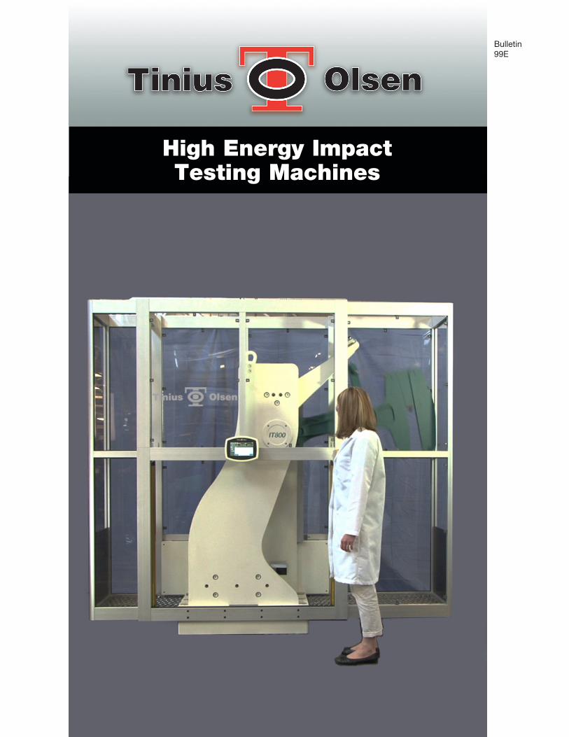
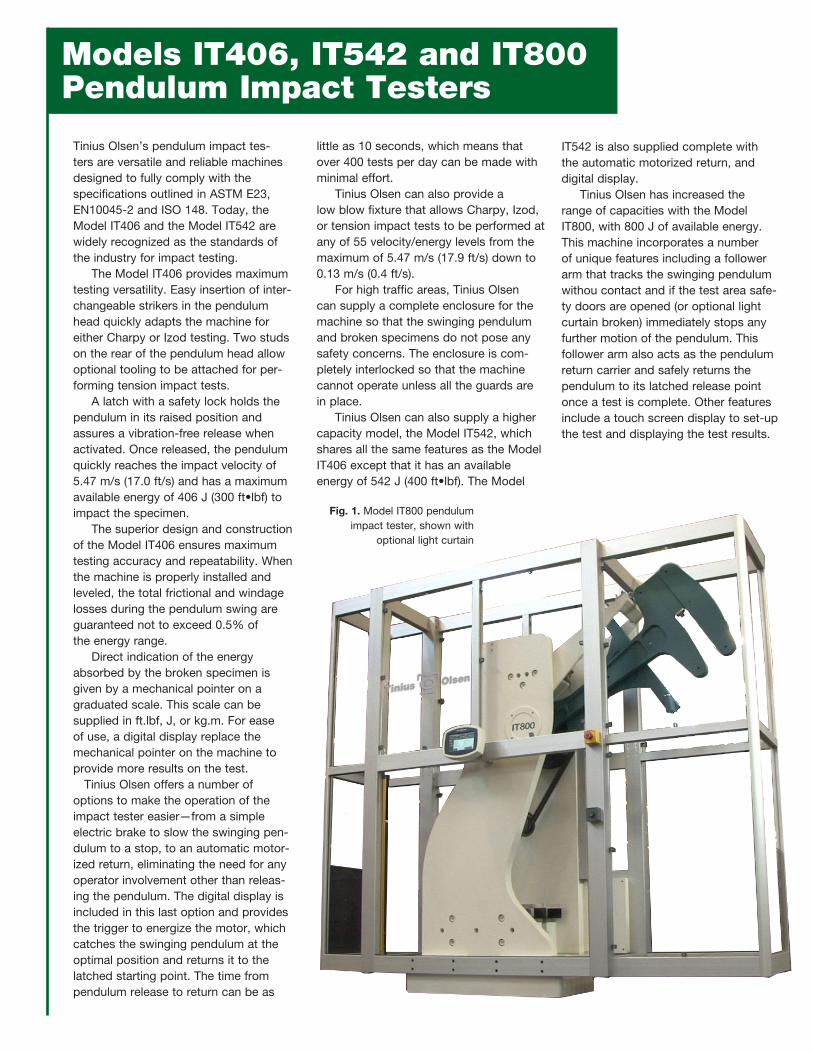
IT542 is also supplied complete with the automatic motorized return, and digital display. Tinius Olsen has increased the range of capacities with the Model IT800, with 800 J of available energy. This machine incorporates a number of unique features including a follower arm that tracks the swinging pendulum withou contact and if the test area safe-ty doors are opened (or optional light curtain broken) immediately stops any further motion of the pendulum. This follower arm also acts as the pendulum return carrier and safely returns the pendulum to its latched release point once a test is complete. Other features include a touch screen display to set-up the test and displaying the test results.
Fig. 1. Model IT800 pendulum impact tester, shown with
optional light curtain

Technical Specifications
Machines with a digital display can be linked to a stand alone PC and connected to Tinius Olsen’s Horizon software. Key features of this software include:• User-selected reporting and exporting
formats.• Built-in SPC programs for X-bar, R,
and frequency distribution charts/his-tograms.
• Test mode allows configuring, run-ning, and saving of tests and results.
• Recall mode permits viewing of pre-viously saved results and performs database maintenance.
Fig. 4. Model IT406 with mechanical pointer on a
graduated scale.
Fig. 5. Close up of Charpy set-up just prior to impact.
Fig. 2. Model IT542 pendulum impact tester shown with
digital display.
Model IT406 IT542 IT800Basic Pendulum J 406 542 800Capacity ft•lb 300 400 590Drop Height m 1.5 1.5 1.5 ft 5 5 5Impact Velocity m/s 5.5 5.5 5.5 ft/s 18 18 18Dimensions mm 2108 x 508 x 1854 2108 x 508 x 1854 2560 x 910 x 2320(WxDxH)* in 83 x 20 x 73 83 x 20 x 73 101 x 36 x 92Weight - Gross (Net) kg 736 (650) 785 (700) 2631 (2313) lb 1620 (1430) 1730 (1543) 5800 (5100)
KEY FEATURES:• Precision, friction com-
pensated, robust test frames.
• Digital display option allows test set-up and result display.
• Digital display option allows simple connec-tion to pc for full test SPC analysis.
• Range of safety features to ensure repetitive secure testing.
Fig. 3. Screenshots of impact testing capabilities within Tinius
Olsen’s Horizon software.
* Width of machine includes total swing clearance.

© 2013, Tinius Olsen 11/13 05-151 Printed in U.S.
Horsham, PA 19044 USA
Redhill, Surrey RH1 5DZ England
www.TiniusOlsen.com [email protected]
Contact Your Local Representative:
Configurations
Charpy— Replaceable shrouds prevent the specimen from rebounding against the pendulum. The striker is bolted to the pendulum and available in either 8 mm (ASTM E23) or 2 mm (BS, DIN, JIS, EN, and ISO) nose radius sizes. An optional set of self-centering tongs is extremely useful for accurately center-ing Charpy specimens, especially those subjected to temperature extremes prior to the test.
Izod—The Izod striker is easily secured in the pendulum while the specimen is clamped in the close clearance slots in the vice. This ensures that the speci-men has the correct vertical alignment while the setting gage ensures that the specimen is at correct height. A wrench is provided for tightening and loosening the specimen in the vise. Note - this con-figuration is not available on the Model IT800.
Tension Impact—The tension impact specimen is threaded into the specimen holder in the pendulum head. Tension is instantaneously applied to the specimen when the holding bar strikes the anvils. This method of support pro-vides uniform distribution of the impact energy over the cross-section of the test specimen. Note - this configuration is not available on the Model IT800.
The different configurations that are supported are as follows:
Fig. 6. View of the Charpy striker from the pendulum head.
Fig. 7. View of the base with the Charpy configuration. The specimen rests horizontally on the Charpy supports (obscured by the protective shrouds). Charpy cen-tering tongs can be seen in front.
Fig. 8. View of the Izod striker from the pendulum head.
Fig. 9. View of the base with the Izod. The specimen is clamped in the vertical position using the front screw.
Fig. 10. View of the tension impact striker from the pendulum head. The specimen is threaded into the ‘striker’ and the holding bar at the back of the pendulum head.
Fig. 11. View of the base with the tension impact configuration.
Specifications subject to change without notice.


