HIGH ENERGY ELECTRON BEAM JOINING OF CERAMIC COMPONENTS/67531/metadc691136/m2/1/high... · HIGH...
7
, \ HIGH ENERGY ELECTRON BEAM JOINING OF CERAMIC COMPONENTS B. N. Turman, S. Jill Glass, John A. Halbleib, Thomas E. Voth, Frank P. Gerstle, Sandia National Laboratories, Albuquerque, New Mexico Jerry R. Clifford Titan Advanced Technologies Group, Albuquerque, New Mexico Pin Yang, Bonnie McKenzie, RECEIVED Abstract Jut 0 3 897 OSTI High strength, hermetic braze joints between ceramic components have been produced using high energy electron beams. With a penetration depth into a typical ceramic of -1 cm for a 10 MeV electron beam, this method provides the capability for rapid, transient brazing operations where temperature control of critical components is essential. The method deposits energy directly into a buried joint, allowing otherwise inaccessible interfaces to be brazed. Because of transient heating, higher thermal conductivity, lower heat capacity, and lower melting temperature of braze metals relative to the ceramic materials, a pulsed high power beam can melt a braze metal without producing excessive ceramic temperatures. We have demonstrated the feasibility of this process related to ceramic coupons as well as ceramic and glass tubes. The transient thermal response was predicted, using as input the energy absorption predicted from the coupled electron-photon transport analysis. The joining experiments were conducted with an RF Linac accelerator at 10-13 MV. The repetition rate of the pulsed beam was varied between 8 and 120x2, the average beam current was varied between 8 and 120 microamps, and the power was varied up to 1.5 kW. These beam parameters gave a beam power density between 0.2 to 2 kW/cmz. The duration of the joining runs varied from 5 to 600 sec. Joining experiments have provided high strength between alumina - alumina and alumina - cermetjoints in cylindrical geometry. These joints provided good hermetic seals. A series of tests was conducted to determine the minimum beam power and exposure time for producing a hermetic seal. This work was supported by the US Department of Energy under Contract DE-AC04-94AL85000. 1. Introduction With a penetration depth of -1 an for a 10 MeV electron beam into a typical ceramic, electron beam joining provides the capability for directing energy into a buried, or inaccessiblejoint, and provides the possibility of transient brazing operations where temperature control of critical components is essential'. Ceramic sealing and joining are important in the commercial and defense sectors. Ceramic insulators and power tubes are increasingly used in generation of high power electrical and microwave components. High temperatures (400-1000°C) are needed to form hermetic ceramic seals. Localized heating of the joint by an electron beam optimized for materials and geometry could open exciting possibilities, such as allowing temperature-sensitive electronic components to be assembled into sub-systems prior to brazing. The rapid braze rates that can be achieved with this process, typically a five minute total heating cycle, offer the potential of a greatly reduced process time for small-lot sealing operations. Ceramics such as Si3N4 and S i c are seeing increasing use for high temperature structural applications such as turbochargers for automobile engines, turbines for aircraft auxiliary power units, stator shrouds for gas turbines for power generation applications, ceramic armor, ceramic thermal protection tiles, and high energy flux mirrors. Although ceramics are being fabricated that can survive these challenging environments,their application is still limited by the lack of suitable technologies for joining them to components such as metal shafts or for joining them to themselves. A limitation of conventionaljoining techniques is that they require that all of the parts to be joined be exposed to high temperatures, which may degrade the performance of these components. Thus alternativejoining techniques are being explored.
Transcript of HIGH ENERGY ELECTRON BEAM JOINING OF CERAMIC COMPONENTS/67531/metadc691136/m2/1/high... · HIGH...

,
\
HIGH ENERGY ELECTRON BEAM JOINING OF CERAMIC COMPONENTS
B. N. Turman, S. Jill Glass, John A. Halbleib, Thomas E. Voth, Frank P. Gerstle,
Sandia National Laboratories, Albuquerque, New Mexico Jerry R. Clifford
Titan Advanced Technologies Group, Albuquerque, New Mexico
Pin Yang, Bonnie McKenzie, RECEIVED
Abstract
Jut 0 3 897 O S T I
High strength, hermetic braze joints between ceramic components have been produced using high energy electron beams. With a penetration depth into a typical ceramic of -1 cm for a 10 MeV electron beam, this method provides the capability for rapid, transient brazing operations where temperature control of critical components is essential. The method deposits energy directly into a buried joint, allowing otherwise inaccessible interfaces to be brazed. Because of transient heating, higher thermal conductivity, lower heat capacity, and lower melting temperature of braze metals relative to the ceramic materials, a pulsed high power beam can melt a braze metal without producing excessive ceramic temperatures. We have demonstrated the feasibility of this process related to ceramic coupons as well as ceramic and glass tubes. The transient thermal response was predicted, using as input the energy absorption predicted from the coupled electron-photon transport analysis. The joining experiments were conducted with an RF Linac accelerator at 10-13 M V . The repetition rate of the pulsed beam was varied between 8 and 120x2, the average beam current was varied between 8 and 120 microamps, and the power was varied up to 1.5 kW. These beam parameters gave a beam power density between 0.2 to 2 kW/cmz. The duration of the joining runs varied from 5 to 600 sec. Joining experiments have provided high strength between alumina - alumina and alumina - cermet joints in cylindrical geometry. These joints provided good hermetic seals. A series of tests was conducted to determine the minimum beam power and exposure time for producing a hermetic seal.
This work was supported by the US Department of Energy under Contract DE-AC04-94AL85000.
1. Introduction
With a penetration depth of -1 an for a 10 MeV electron beam into a typical ceramic, electron beam joining provides the capability for directing energy into a buried, or inaccessible joint, and provides the possibility of transient brazing operations where temperature control of critical components is essential'. Ceramic sealing and joining are important in the commercial and defense sectors. Ceramic insulators and power tubes are increasingly used in generation of high power electrical and microwave components. High temperatures (400-1000°C) are needed to form hermetic ceramic seals. Localized heating of the joint by an electron beam optimized for materials and geometry could open exciting possibilities, such as allowing temperature-sensitive electronic components to be assembled into sub-systems prior to brazing. The rapid braze rates that can be achieved with this process, typically a five minute total heating cycle, offer the potential of a greatly reduced process time for small-lot sealing operations. Ceramics such as Si3N4 and Sic are seeing increasing use for high temperature structural applications such as turbochargers for automobile engines, turbines for aircraft auxiliary power units, stator shrouds for gas turbines for power generation applications, ceramic armor, ceramic thermal protection tiles, and high energy flux mirrors. Although ceramics are being fabricated that can survive these challenging environments, their application is still limited by the lack of suitable technologies for joining them to components such as metal shafts or for joining them to themselves. A limitation of conventional joining techniques is that they require that all of the parts to be joined be exposed to high temperatures, which may degrade the performance of these components. Thus alternative joining techniques are being explored.

\
2. Description of Experiments
A development program has tested a variety of ceramic materials under electron beam heating to understand the limits and capabilities for transient heating and joining. Over sixty ceramic tubes, and more than thirty-five coupon combinations have been joined using a matrix of beam power and exposure time settings to identify successful operating ranges. Several braze alloys have been tested. The quality of the joint was evaluated based on metallurgy, hermeticity, and shear strength. These joining experiments were conducted with the Titan RF Linac accelerator at 10-13 MV. The repetition rate of the pulsed beam was varied between 8 and 120 EIz, the average beam current was varied between 8 and 120 microamperes, and the power was-varied up'to 1.5 kW. These beam parameters gave a beam power density between 0.2 to 2 kW/cm2. The duration of the joining runs varied from 5 to 600 sec. Moderate vacuum, at the level of 1 millitom or less, was used to minimize braze oxidation. Three basic specimen configurations were tested. The first consisted of two square coupons with approximate dimensions of 1 cm x 1 cm x 0.4 cm. Joining was conducted by placing the joining material between the two coupons on the 1 cm x 1 cm face. The samples were stationary and the beam axis was perpendicular to the coupon face. The second joining geometry consisted of cylindrical tubes with circular discs for lids. The third configuration joined two ceramic tubes with transverse irradiation onto an equatorial joint. For both tube geometries a motor-driven fucture rotated the sample under the electron beam. A 500 gram load on the sample ensured sufficient contact and spreading of the braze. The beam was aligned so that the area to be joined was uniformly heated around the circumference as the part rotated under the beam at a speed of either 1000 rpm or 16 rpm. To minimize radiative and conductive losses, the rotating fixture included a radiation shield and low- conductivity ceramic thermal insulation. -
3. Radiation and Thermal Transport Modeling
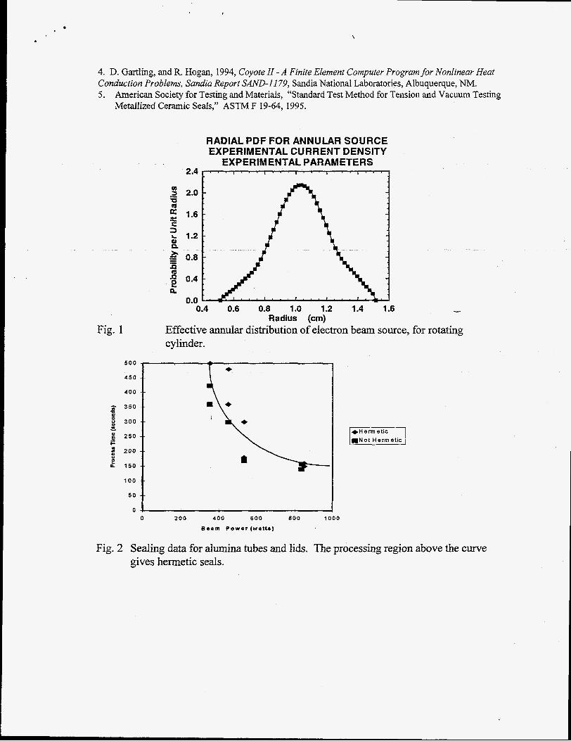
High-energy electron beam brazing was modeled numerically in order to enhance the design and operation of the brazing apparatus. The transient thermal response of the part was predicted, using as input the energy absorption rate predicted from the coupled electron-photon transport analysis. In all analyses, the geometry was assumed to be axisymmetric. Power deposition resulting ftom electron beam irradiation was modeled by simulating the coupled electron-photon transport within the apparatus. In the present application, electron-beam energy deposition was simulated with the Integrated TIGER Series (ITS) code system2 The ITS system combines conventional microscopic (single scattering) Monte Carlo calculations for photon transport with a macroscopic random walk technique for electron transpod. Coupling of the two species is complete in the sense that the physical model includes all relevant processes for the production of photons by electrons and the production of electrons by photons. The annular distribution of the 10 MeV electron source for the lid brazing geometry is plotted in Figure 1.
Thermal transport was governed by the thermal diffusion equation, with temperature independent density and thermal conductivity. Specific heat was assumed constant for all materials except the braze. Braze specific heat was assumed to vary, with an increased value between the liquidus and solidus temperatures to account for latent heat effects during melting. Thermal boundary conditions were typically assumed to be radiative from exposed surfaces while convective losses were assumed negligible as the experiments simulated were performed in a vacuum. The thermal analysis was performed using COYOTE 11, which is a finite element code for solving the non-linear heat diffusion equation4. The predicted power requirement was found to be about 220 W average beam power. Experimentally we confinned that this was a reasonable and efficient power range for joining. The time to liquidus temperature, plus 50" C, can be summarized in the following scaling relation, where dimensionless time, Fo, is related to the dimensionless beam current, I, by:
Fo = ta./h2 = 1701-' 31
= (lbEflb)/@s(Tp-Ti)) (1) where t is time, V,, is the braze volume, h is the braze thickness, I, is the average beam current, E, is the beam kinetic energy, k, is the tube and lid's thermal conductivity, a is the thermal diffusivity of the braze, Tp = T, + 50' C, and T, and T, are the liquidus and initial temperatures respectively.

4. Ceramic Coupon Joining
Coupon joining tests were conducted using various ceramic substrates and brazes. The purpose of these experiments was to evaluate the effect of beam parameter variations on bonding &en,& and to observe microscopic features of the braze joint. The substrate materials included Si,N,, Sic, A1,0,, and Mo-A120, cermet. Brazes included Ticusil, Cusil ABA, Incusil ABA, Nioro ABA, and Easy Flo 45. The first three brazes contain titanium as an active element to promote wetting and reaction with the ceramic. Nioro ABA contains vanadium as the active element.
Shear strength tests indicated that most of the joints had good mechanical integrity, with the exception of the Sic-Sic joints. Strengths ranged between 88 MPa (12.7 kpsi) for Si,N,- Si,N, coupons bonded with Ticusil and 220 MFa (3 1.9 @si) for A1,0,- A1,0, coupons bonded with Ticusil. The strongest Si,N, - Si,N, bonds were produced with Ticusil braze and silicon-coated Si,N, surfaces. The stren-gh in this case was in excess of I85 m a , the limit of testing for the shear stren,@ test fixture. Cermet on alumina samples also produced high strengths in the range of 170-180 MPa with both Ticusil and Nioro ABA brazes. The following Table gives the stren-4 measurements for these materials, ignoring the effect of braze choice. To fxst order, the choice of braze material appears to have limited effect within the statistical error of the experiment. Ultrasound results indicated poor contact of Sic-Sic coupons bonded with Ticusil.
Table 1 Summary of Coupon Sample Shear Strength -
Ceramic Material Number of Mean Shear Standard Dev. Std. DevMean
Silicon Nitride 9 142 42 0.29 Ti-coated Silicon 1 185 Nitride Silicon Carbide 3 57 20 0.34 Alumina 3 1 92 20 0.10
Samples Stren-gh (MPa) @Pa)
5. Alumina Tube Sealing
Electron beam brazing was conducted with four brazes: Cusil ABA (melt temperature 815 'C), Ticusil(850 'C), Incusil ABA (7 15 'C), and Easy Flo 45 (6 18 'C). Cusil ABA appeared to give the best results based on its melting, wetting behavior, joint appearance, and properties of the joints. The use of Ti (1.75%) as an active element in this braze alloy helps promote wetting of the alumina surfaces and reactive bonding by the braze. At vacuum pressure higher than a few millitorr, we observed significant oxidation problems with Ticusil, which has the highest Ti content and is thus most susceptible to oxidation. Below 1 millitorr, we observed no evidence of oxidation. The higher melting point of Ticusil ABA caused some cracking of the ceramic due to thermal shock. Microcracking of the braze and non-uniform reactions were observed with Incusil ABA braze. Easy Flo 45, without a reactive component, did not form a reaction layer. Therefore, Cusil ABA was used as the braze of choice for most of these experiments with alumina sealing.
I
The experimental processing time is plotted against the beam average power in Figure 2, showing the minimum time required to obtain hermetic seals. Hermeticity was determined with a helium leak detector at torr. Samples that were hermetically sealed are shown as diamonds, and those not sealed are plotted as squares. Shorter times can be used to produce a hermetic seal as the beam current increases, with an apparent asymptotic minimum time of 100 - 150 seconds.
Ultrasound transmission was used to obtain a non-destructive picture of the joint. The quality of the bond is determined by the principle that well-bonded regions transmit the ultrasonic signal more effectively (or have a lower impedance) than those that are weakly bonded. The microstructures of these joints were studied, placing special attention on the differences between "strong" and "weak" bond regions. In general, we found that regions with a "strong" bond exhibited a thicker reaction layer with a coarser eutectic

microstructure in the braze, as shown in Fi,pre 3. Development of a reaction layer, like most chemical reactions, depends on the processing temperature and time. This immediately suggests that a combination of sufficient processing temperature and reaction time is essential to develop a thick reaction layer for good bonding. Comparing the active brazing alloys, Cusil ABA seems to work best with the e-beam joining process and yields the best hermeticity and bond strength. The reaction layer was found to be much thinner for Incusil ABA than for Cusil ABA, and hcusil ABA tended to form microcracks in the braze material.
Tensile stren,& measurements employed an ASTM standard geometry’. For this test, an hour-glass shaped sample was produced by joining two funnel-shaped ceramic sections at the middle, with a joint diameter of I .6 cm. The sample was then pulled until fracture occurred. The results of those tensile tests are given in Figure 4. Two sets of experiments are shown in the figure. The first is at 840 watts beam power, approximately the maximum power at which alumina can be joined without inducing thermal shock. Tensile strenag& is seen to increase rapidly with increased process time. The second sample set was operated with an initial beam power of 530 watts, until the braze melt temperature was reached (100 seconds). The beam power was then reduced to 280 watts, maintaining the temperature at the melt point for the remainder of the process. This approach avoided overheating the ceramic, while providing time to form the reaction zone. We have not completed testing with this approach; the plot indicates that longer time is needed to develop the reaction zone, on the order of 600 seconds to reach the strength range of 100 m a . We also conducted experiments with a conventional oven braze process, in which the sample was held constant at the braze melt temperature for 600 seconds. The average stren,g$h in that case was 98 MPa, consistent with the extrapolation of strength vs. process time for the low power electron bzam processing.
These tensile stren,oth data show a direct relationship with reaction time, with peak strength at 600 seconds, of about 100 m a . From a thermodynamic point of view, the lower power e-beam experiments are equivalent to the conventional furnace brazing process, and this equivalence is confirmed in the stren-oth data with a correlation coefficient of 0.94. The conclusion from Figure 4 is that high strength joints can be produced in about one-fourth the time of the conventional braze process using the electron beam brazing process at 840 watts. An added benefit is that electron beam joining allows local heating of the braze area, rather than full heating of the component. A conventional braze process appears to produce the same results as the 530 watt/280 watt electron beam process.
6. Summary
We have successfully joined and sealed ceramic tubes, demonstrating the feasibility of deep penetration electron beam joining with 10 MeV electrons. Joining experiments have provided high strength joints between alumina - alumina, and alumina - cermet in cylindrical geometry. Joint strengths of up to 1 18 MPa (1 7.1 kpsi) were measured. Square coupon samples were also joined and tested for shear stren,@. Shear strengths of over 200 MPa (29.0 kpsi) were measured for Si,N, - Si3N4 and A1,0, - A1,03 samples. Hermetic seals between tubes and lids of alumina - alumina, alumina - cermet have been obtained. A series of tests was conducted to determine the minimum beam power and exposure time for producing a hermetic seal.
I
7. References
1. B. N. Turman, S . J. Glass, J. A. Halbleib, D. R Helmich, and R. E. Loehman, “Electron Beam Joining of Structural Ceramics,” Sandia National Laboratories, SAND95-0595, April 1995. 2. J. A. Halbleib, R. P. Kensek, G. D. Valdez, S . M. Seltzer, and M. J. 3erger, 1992, “ITS: The Integrated TIGER Series of ElectrodPhoton Transport Codes - Version 3.0,” IEEE Transactions of Nuclear Science,
3. M.J Berger, 1963, “Monte Carlo Calculation ofthe Penetration and Diffusion of Fast Charged Particles,” in Methoak in Computational Physics, Vol. 1, Academic, New York.
Vol. 39, pp. 1025-1030.
\
4. D. Gartling, and R. Hogan, 1994, Coyote II - A Finite Element Computer Program for Nonlinear Heat Conduction Problems, Sandia Report SAND-1 1 79, Sandia National Laboratories, Albuquerque, NM. 5. American Society for Testing and Materials, “Standard Test Method for Tension and Vacuum Testing
Metalized Ceramic Seals,” ASTM F 19-64, 1995.
RADIAL PDF FOR ANNULAR SOURCE EXPERIMENTAL CURRENT DENSITY
EXPERIMENTAL PARAMETERS
0.4 0.6 0.8 1.0 1.2 1.4 1.6 1
Effective annular distribution of eIectron beam source, for rotating cylinder.
Radius (cm) Fig. 1
5 0 0
450
400 - -
3 350 - -
4 300 - -
E 2 5 0 - -
0
e
m N o t Hermetic
- ; 200 - - D 2 150 - -
100 - - I t Fig. 2
_ . 0 2 0 0 400 6 0 0 8 0 0 1000
B e r m P o w e r (wat ts)
Sealing data for alumina tubes and lids. The processing region above the curve gives hemetic seals.

L
50 pm
Fig.3 Scanning Electron Micrograph (SEM) cross-section through an alumina-Cusil ABA-Alumina .. braze joint: (a) - strong, .- hermetic joint, and (b) weak, non-hermetic joint.
BO -
+ 70 --
e 60 -- 2 50 --
-- 5 m E 40 tj 2 .- 30 --
g 20 -- ln c
Fig. 4.
lo i 0- 0 50 100 I50 200 250
Process Time (seconds)
+ 840 watts
Tensile strength of alumina-Cusil ABA-alumina ceramic samples in a "tensile button" test configuration5.
DISCLAIMER
This report was prepared as an a m u n t of work sponsored by an agency of the United States Government. Neither the United States Government nor any agency thereof, nor any of their emplcyccs, makes any warranty, express or implied, or assumes any legal liability or responsi- bility for the accuracy, completeness, or usefulness of any information, apparatus, product, or process disclosed, or represents that its use would not infringe privately owned rights. Refer- ence herein to any specific commercial product, process, or service by trade name, trademark, manufacturer, or otherwise does not necessarily constitute or imply its endorsement, r m m - mendation, or favoring by the United States Government or any agency thereof. The views and opinions of authors expressed herein do not necessarily state or reflect those of the United States Government or any agency thereof.