High-End Corner Radar Reference Design
16
Design Guide: TIDEP-01027 High-End Corner Radar Reference Design Description This reference design provides a foundation for corner radar applications to meet NCAP R79 safety requirements using the AWR2944 evaluation module (EVM). The design allows users to estimate and track the position (in the azimuthal plane) and velocity of objects in the field of view of the device up to 200 m. This application focuses on corner and front long- range radar systems for multiple functions such as blind spot detection, front cross-traffic assist, and lane change assist. The design also demonstrates the TI compression engine and hardware accelerator (HWA) capabilities. Resources TIDEP-01027 Design Folder AWR2944 Product Folder MMWAVE-MCUPLUS-SDK Product Folder TCAN1043-Q1 Product Folder TMP112 Product Folder Ask our TI E2E ™ support experts Features • Enables car manufacturers to meet NCAP R79 safety requirements using a single chip radar sensor • Provides unmatched corner radar performance with best in class RF performance enabled by a fourth transmitter for 33% higher angular resolution than traditional 3 transmitter devices • Detect and track objects (such as cars and trucks) up to 200 meters away with velocity of ±140 kilometers per hour (kmph) • Antenna azimuth field of view ±80º with azimuth angular resolution of approximately 9.5º • Demonstrates the following AWR2994 capabilities: – TX phase shift – Data compression – HWA with Doppler division multiple access (DDMA) processing chain provided by mmWave SDK • Builds customer confidence on mmWave device capabilities • Improves the customer development cycle (for example, hardware redesign and software effort) Applications • Medium and short range radar • Long range radar AWR2944 PC GUI TX RX www.ti.com Description TIDUF01 – NOVEMBER 2021 Submit Document Feedback High-End Corner Radar Reference Design 1 Copyright © 2021 Texas Instruments Incorporated
Transcript of High-End Corner Radar Reference Design

Design Guide: TIDEP-01027High-End Corner Radar Reference Design
Description
This reference design provides a foundation for corner radar applications to meet NCAP R79 safety requirements using the AWR2944 evaluation module (EVM). The design allows users to estimate and track the position (in the azimuthal plane) and velocity of objects in the field of view of the device up to 200 m. This application focuses on corner and front long-range radar systems for multiple functions such as blind spot detection, front cross-traffic assist, and lane change assist. The design also demonstrates the TI compression engine and hardware accelerator (HWA) capabilities.
ResourcesTIDEP-01027 Design FolderAWR2944 Product FolderMMWAVE-MCUPLUS-SDK Product FolderTCAN1043-Q1 Product FolderTMP112 Product Folder
Ask our TI E2E™ support experts
Features• Enables car manufacturers to meet NCAP R79
safety requirements using a single chip radar sensor
• Provides unmatched corner radar performance with best in class RF performance enabled by a fourth transmitter for 33% higher angular resolution than traditional 3 transmitter devices
• Detect and track objects (such as cars and trucks) up to 200 meters away with velocity of ±140 kilometers per hour (kmph)
• Antenna azimuth field of view ±80º with azimuth angular resolution of approximately 9.5º
• Demonstrates the following AWR2994 capabilities:– TX phase shift– Data compression– HWA with Doppler division multiple access
(DDMA) processing chain provided by mmWave SDK
• Builds customer confidence on mmWave device capabilities
• Improves the customer development cycle (for example, hardware redesign and software effort)
Applications• Medium and short range radar• Long range radar
AWR2944PC GUI
TX
RX
www.ti.com Description
TIDUF01 – NOVEMBER 2021Submit Document Feedback
High-End Corner Radar Reference Design 1
Copyright © 2021 Texas Instruments Incorporated

1 System Description
Autonomous control of a vehicle provides quality-of-life and safety benefits in addition to making the relatively mundane act of driving safer and less difficult. The quality-of-life features include the ability of a vehicle to park itself or to determine whether a lane change is possible and provide features like automatic cruise control—where a vehicle maintains a constant distance with respect to the car ahead of it, essentially tracking the velocity of the car in front of it. Autonomous breaking and collision avoidance are safety features that prevent accidents caused by driver inattention. These features work by observing the area around (front, rear, and adjacent) a car and alerting the autonomous driving subsystems if obstacles are observed that are likely to hit the car. Implementing these technologies require a variety of sensors to detect obstacles in the environment and track their velocities and positions over time.
1.1 Why use Radar?Frequency-modulated continuous-wave (FMCW) radars allow the accurate measurement of distances and relative velocities of obstacles and other vehicles; therefore, radars are useful for autonomous vehicular applications (such as lane change assist and cross traffic alert) and car safety applications (autonomous breaking and collision avoidance). An important advantage of radars over camera and light-detection and ranging (LIDAR)-based systems is that radars are relatively immune to environmental conditions such as the effects of rain, dust, and smoke. Because FMCW radars transmit a specific signal (called a chirp) and process the reflections, they work in complete darkness and also bright daylight (radars are not affected by glare). When compared with ultrasound, radars typically have a much longer range and much faster signal transit times.
1.2 TI Corner Radar DesignThe TIDEP-01027 is an introductory application where the AWR2944 device is configured for corner radar applications to track objects within a 200-m range.
1.3 Key System SpecificationThis reference design uses Doppler division multiple access (DDMA) processing where most of processing is done on the HWA and some intermediate tasks are offloaded to the DSP.
Table 1-1. Key System SpecificationPARAMETER SPECIFICATIONS DETAILS
Maximum range (m) 253 This is the maximum range supported by the chirp configuration shown in Table 2-1. The maximum detectable range for a given object depends on the Radar cross section (RCS) of the object
Range resolution (m) 1.3 The theoretical achievable resolution by AWR2944 is 3.75 cm based on 4 GHz bandwidth
Maximum velocity (kmph) ±143 This is the native maximum velocity obtained after velocity disambiguation in DDMA. This specification can be improved by either using the range-rate in the tracker or higher-level algorithms
Velocity resolution (kmph) 0.37 This parameter represents the capability of the radar sensor to distinguish between two or more objects at the same range but moving with different velocities
Azimuth angular resolution (Deg) 9.5 This is the native azimuth angular resolution based on the virtual array aperture
System Description www.ti.com
2 High-End Corner Radar Reference Design TIDUF01 – NOVEMBER 2021Submit Document Feedback
Copyright © 2021 Texas Instruments Incorporated
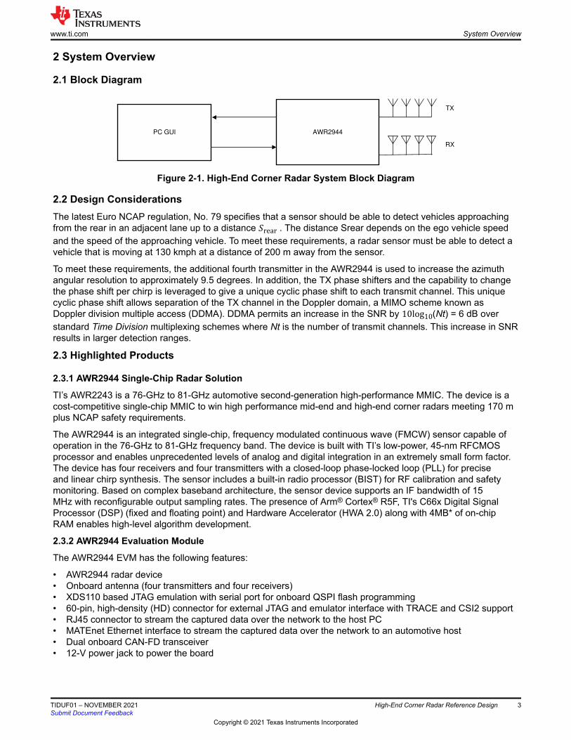
2 System Overview
2.1 Block Diagram
AWR2944PC GUI
TX
RX
Figure 2-1. High-End Corner Radar System Block Diagram
2.2 Design ConsiderationsThe latest Euro NCAP regulation, No. 79 specifies that a sensor should be able to detect vehicles approaching from the rear in an adjacent lane up to a distance Srear . The distance Srear depends on the ego vehicle speed and the speed of the approaching vehicle. To meet these requirements, a radar sensor must be able to detect a vehicle that is moving at 130 kmph at a distance of 200 m away from the sensor.
To meet these requirements, the additional fourth transmitter in the AWR2944 is used to increase the azimuth angular resolution to approximately 9.5 degrees. In addition, the TX phase shifters and the capability to change the phase shift per chirp is leveraged to give a unique cyclic phase shift to each transmit channel. This unique cyclic phase shift allows separation of the TX channel in the Doppler domain, a MIMO scheme known as Doppler division multiple access (DDMA). DDMA permits an increase in the SNR by 10log10(Nt) = 6 dB over standard Time Division multiplexing schemes where Nt is the number of transmit channels. This increase in SNR results in larger detection ranges.
2.3 Highlighted Products
2.3.1 AWR2944 Single-Chip Radar Solution
TI’s AWR2243 is a 76-GHz to 81-GHz automotive second-generation high-performance MMIC. The device is a cost-competitive single-chip MMIC to win high performance mid-end and high-end corner radars meeting 170 m plus NCAP safety requirements.
The AWR2944 is an integrated single-chip, frequency modulated continuous wave (FMCW) sensor capable of operation in the 76-GHz to 81-GHz frequency band. The device is built with TI’s low-power, 45-nm RFCMOS processor and enables unprecedented levels of analog and digital integration in an extremely small form factor. The device has four receivers and four transmitters with a closed-loop phase-locked loop (PLL) for precise and linear chirp synthesis. The sensor includes a built-in radio processor (BIST) for RF calibration and safety monitoring. Based on complex baseband architecture, the sensor device supports an IF bandwidth of 15 MHz with reconfigurable output sampling rates. The presence of Arm® Cortex® R5F, TI's C66x Digital Signal Processor (DSP) (fixed and floating point) and Hardware Accelerator (HWA 2.0) along with 4MB* of on-chip RAM enables high-level algorithm development.
2.3.2 AWR2944 Evaluation Module
The AWR2944 EVM has the following features:
• AWR2944 radar device• Onboard antenna (four transmitters and four receivers)• XDS110 based JTAG emulation with serial port for onboard QSPI flash programming• 60-pin, high-density (HD) connector for external JTAG and emulator interface with TRACE and CSI2 support• RJ45 connector to stream the captured data over the network to the host PC• MATEnet Ethernet interface to stream the captured data over the network to an automotive host• Dual onboard CAN-FD transceiver• 12-V power jack to power the board
www.ti.com System Overview
TIDUF01 – NOVEMBER 2021Submit Document Feedback
High-End Corner Radar Reference Design 3
Copyright © 2021 Texas Instruments Incorporated
3.3VAWR294x
TCAN1043
CAN FD1 PHY
TCAN1042
CAN FD2 PHY
MIPI 60-pin
Connector
Debug 60-pin
Connector
CAN
Interface 1
CAN
Interface 2
DP83867E
Ethernet PHY
RJ45 Ethernet
Jack
TPS73501
2.5V LDOTLV733
1V LDO
PJ-063AH
DC Jack
LP877451-Q1
INA226
Current
Sensor INA226
Current
Sensor
12 V
1.8 V
3.3 V1.8 V 1.2 V
3.3 V
1.8 V
CAN FD1
CAN FD2
1.8V 3.3V
1V2.5 V
RGMII, MDIO
GD25B64CWAG
FLASH
QSPI
3.3 VIO
TM4C1294NCPDT
XDS110
USB
RS232,
MSS/BSS Logger,
JTAG
3.3 V
FT4232H
FTDI
USB
SPI
I2C
RS232
UART
NERRIN
NRST
WRMRST
SOP
TMP112
Temp Sensor
I2C
40 MHz
XTAL
External CLK
option
5 V
5 V
3.3 VIO
3.3 VIO
TRACE, CSI2, JTAG
GPADC
SPI
I2C
WRMRST
NERRIN
NERROUT
EPWMs
GPIOs
LVDS
INA226
Current
Sensor
1.2 V
TPS79601
1.7V LDO
3.3V
VPP SUPPLY
INA226
Current
Sensor
1.0 V
3.3 V
1.0 V
LM63635-Q1
12 V
DP83867E
Ethernet PHYMATEnet
3.3 VIO 3.3 V 1 VTPS73501
2.5 V LDO
12 V
VSLEEP
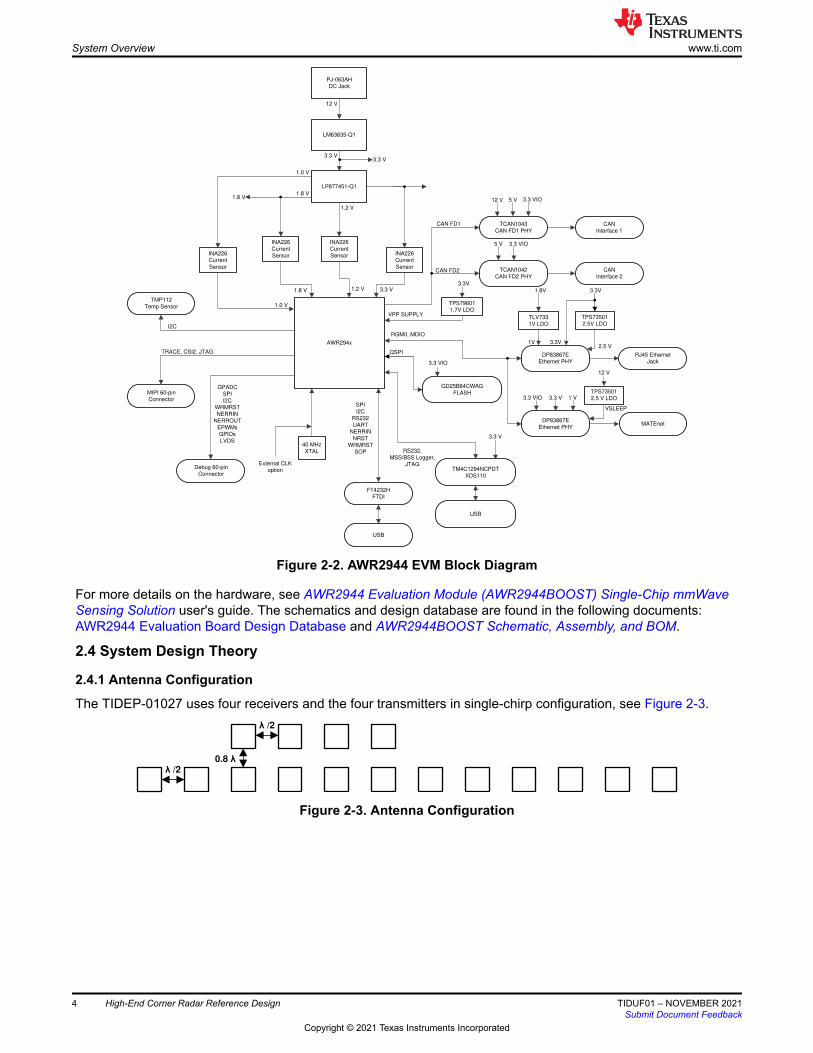
Figure 2-2. AWR2944 EVM Block Diagram
For more details on the hardware, see AWR2944 Evaluation Module (AWR2944BOOST) Single-Chip mmWave Sensing Solution user's guide. The schematics and design database are found in the following documents: AWR2944 Evaluation Board Design Database and AWR2944BOOST Schematic, Assembly, and BOM.
2.4 System Design Theory
2.4.1 Antenna Configuration
The TIDEP-01027 uses four receivers and the four transmitters in single-chirp configuration, see Figure 2-3.
��/2
0.8 �
��/2
Figure 2-3. Antenna Configuration
System Overview www.ti.com
4 High-End Corner Radar Reference Design TIDUF01 – NOVEMBER 2021Submit Document Feedback
Copyright © 2021 Texas Instruments Incorporated

2.4.2 Chirp Configuration and System Performance
To achieve the specific corner radar, use a case with a visibility range of 200 m and memory availability of the AWR2944. Table 2-1 lists the chirp configuration used.
Table 2-1. Chirp ConfigurationPARAMETER CONFIGURATIONIdle time (μs) 5
ADC start time (μs) 5
Ramp end time (μs) 18.83
Number of ADC samples 384
Frequency slope (MHz/μs) 8.883
MIMO (1 → yes) 1
Number of chirps per profile 768
Effective chirp time (μs) 23.83
Bandwidth (MHz) 114
Frame length (ms) 250
Table 2-2. System Performance ParameterPARAMETER SPECIFICATIONS
Range resolution (m) 1.3
Maximum distance (m) 200
Native maximum velocity (kmph) 140
NoteThe configuration and parameters in Table 2-1 and Table 2-2 are based on the current application release but not limited by the device.
A single legacy frame is used for this application where all the chirps are connected with one profile configuration.
2.4.3 Data Path
The block diagram in Figure 2-4 shows the processing data path to the BSD, LCA, and CTA applications.
Acquisition
(Radar frontend)
rangeproc DPU
(HWA)
dopplerproc-DDMA DPU
(DSS+HWA)
Elevation FFT +
Finalization
(DSS)
RANSAC, Gtrack
(MSS)
Output Results over
UART
(MSS)
Figure 2-4. DDMA Processing Datapath Flow
www.ti.com System Overview
TIDUF01 – NOVEMBER 2021Submit Document Feedback
High-End Corner Radar Reference Design 5
Copyright © 2021 Texas Instruments Incorporated

2.4.4 Chirp Timing
Figure 2-5 shows the timing of the chirps and subsequent processing in the system.Next Frame
Acquisition time
HWA
DSS
MSS
rangeproc DPU
dopplerproc-DDMA DPU
Elevation FFT +
Finalization
RANSAC, Gtrack
Frame period
Output Results over UART
Interframe time
Figure 2-5. Chirp Timing Sequence
Chirp acquisition happens in the radar front end. The front end is configured via mmwavelink in accordance with the chirp configuration.
The core of the data path processing - from chirp acquisition to pointcloud output is divided into the following high-level blocks: rangeproc data processing unit (DPU), dopplerproc-DDMA DPU, elevation FFT, and finalization.
As the acquisition occurs, rangeproc DPU calculates the first dimensional FFT chirp-by-chirp in parallel to the acquisition, compresses the output, and stores it in memory as the compressed radarcube.
Next, the dopplerproc-DDMA DPU decompresses the radarcube one slice at a time and calculates for each slice both velocity and azimuth angle information by taking appropriate FFTs. The dopplerproc-DDMA DPU also performs DDMA demodulation to get the correct velocity out of six possible hypotheses as per the DDMA scheme. Finally, the dopplerproc-DDMA DPU also computes range CFAR and local maximum along range. The dopplerproc-DDMA DPU combines these to produce the object list. The dopplerproc-DDMA DPU utilizes both the hardware accelerator and DSP parallelly to achieve this.
After this step, the elevation FFT is performed on the DSP, followed by the finalization step that computes the Cartesian coordinates and velocity of the detected objects.
After this, RANSAC and GTrack algorithms run on the MSS to produce a target list for the scene. A brief overview of these algorithms is given in later sections. As Figure 2-5 shows, this part of the processing overruns into the next frame. This overrun is by design as it enables the parallel utilization of MSS for GTrack, RANSAC, and data transmission over UART while the rest of the processing happens on HWA+DSP for the next frame.
For more details on the application flow and processing, see the mmWave software development kit (SDK).
2.4.5 eDMA Configuration
Large-scale data movement between memories is accomplished using the EDMA. Using the EDMA is more efficient than using the processor to move data because while the data movement is being completed, the DSP and HWA can continue to process data. The EDMAs work on a ping-pong buffer, meaning that as the ping buffer is being filled, the pong buffer can be used by the HWA or DSP for processing.
The major data transfers necessary include:
• Moving the compressed 1D FFT output from the rangeproc DPU into the L3 memory. This forms the compressed radarcube.
• Fetching one slice of the compressed radarcube and copying it to HWA memory for decompression.• Copying decompressed slice of radarcube into a scratch buffer in L3 for further processing.• Copying decompressed radarcube slice one range-gate at a time into HWA for Doppler processing.
System Overview www.ti.com
6 High-End Corner Radar Reference Design TIDUF01 – NOVEMBER 2021Submit Document Feedback
Copyright © 2021 Texas Instruments Incorporated

• Moving 2D FFT output from HWA memory to Doppler FFT scratch submatrix buffer in L2.• Moving outputs of CFAR, Local Max, and azimuth FFT from HWA memory into buffers in L2.• Triggering the HWA processing upon relevant input EDMA completion (writing a one hot signature into the
appropriate HWA register via chained EDMA).
2.4.6 Memory Allocation
The AWR2944 has the following memories:
• DSS L3 RAM of 2.5MB (see Note)• DSS L2 RAM of 384KB• DSS L1D RAM of 32KB• DSS L1P RAM of 32KB• MSS L2 RAM of 960KB
Note
L3 RAM for AWR2944 ES1.0: 2.25MB, ES2.0: 3MB.
Of the 32KB for L1P RAM and L1D RAM available, half (16KB) of the L1P RAM and half (16KB) of the L1D RAM are used as cache. The remaining half is reserved for code and data, and is unused.
DSS L2 RAM is used for:• Text section (code)• Data scratch buffers• DDMA Doppler FFT Demodulated submatrix• RTOS task stacks
DSS L3 RAM is used for:• Storing the compressed radarcube• Storing slices of decompressed radarcube for processing in scratch buffer• Object list
MSS L2 RAM is used for:
• Text section (code)• Copying pointcloud in L3 produced by DSS. This allows DSS to work on next frame in parallel.• Converting between Cartesian and polar coordinate systems to interface with RANSAC and GTrack
algorithms• Buffers for GTrack
Processing radar signals requires a large number of scratch buffers for each step of the processing stages. The available memory is used efficiently by overlaying the scratch buffers. A scratch buffer used in a previous stage can be re-used in the current stage. More details for this memory layout are found in the mmWave SDK documentation.
2.4.7 DDMA
Doppler division multiple access (DDMA) is a MIMO scheme that allows simultaneous transmission of all TX channels. This allows an increase in the transmit power and hence higher SNR. In DDMA, the orthogonality between different TX channels is obtained by coding each TX with a unique cyclic phase sequence using the phase shifters. Figure 2-6 illustrates the working of DDMA modulation. In time domain, a unique phase shift is applied to each TX channel. This phase value is constant per-chirp and increases as the chirp index increases. If there are Nt transmitters, each transmitter is modulated with phase ωk = 2π k − 1Nt , is the chirp index. The
example in Figure 2-6 has Nt = 3. The orthogonality happens in the Doppler frequency domain as shown in Figure 2-7. Therefore, after Doppler FFT, the signals from different TX channels are naturally separated. However, due to Doppler frequency multiplexing, the allowed maximum target velocity is reduced by a factor of Nt , similar to time division Multiplexing (TDM) MIMO. It is possible to recover the maximum velocity using hypothesis testing with zero padding or phase dithering.
www.ti.com System Overview
TIDUF01 – NOVEMBER 2021Submit Document Feedback
High-End Corner Radar Reference Design 7
Copyright © 2021 Texas Instruments Incorporated

Figure 2-6. DDMA Modulation nonEmpty
Doppler
Range
2D-FFT Output
±Vmax ±Vmax/3 Vmax/3 Vmax
Figure 2-7. Doppler Spectrum in DDMA
2.4.8 Empty Subband Based DDMA
TX channels can be coded to introduce empty-bands in the Doppler spectrum. This allows more robust velocity disambiguation and Doppler-bin to TX-channel mapping in DDMA. To introduce two empty Doppler subbands, the phase added to each TX channel is modified as ωk = 2π k − 1Nt+ 2 . Figure 2-8 and Figure 2-9 show the
range-Doppler plane with Nt = 4 and two empty-bands. The locations of these empty Doppler subbands are used to find the hypothesis that will determine the correct TX channel mapping and allow velocity disambiguation as shown in Figure 2-10.
Figure 2-8. DDMA Modulation
Doppler
Range
Figure 2-9. Doppler Spectrum in DDMA With 4 Transmitters and 2 Empty Subbands
Hypothesis 1
Hypothesis 6
Hypothesis 2
Hypothesis 3
Hypothesis 4
Hypothesis 5
Figure 2-10. Different Hypothesis Corresponding to Different Empty Band Locations
2.4.9 RANSAC
Radar measures the relative radial velocity between the target and radar sensor. In several scenarios, an understanding of whether the relative velocity is due to the movement of the target or the movement of the ego-vehicle itself is required. In this reference design, we fit the velocity profile (radial velocity as a function of the azimuth angle) of the detected points to a motion model using a statistical algorithm called RANSAC (Random sampling and Consensus) to distinguish between the reflections from moving and stationary targets in the ego-vehicles environment. More details about the algorithm are found in Instantaneous ego-motion estimation
System Overview www.ti.com
8 High-End Corner Radar Reference Design TIDUF01 – NOVEMBER 2021Submit Document Feedback
Copyright © 2021 Texas Instruments Incorporated

using Doppler radar (5). The radar detected points that have been classified as coming from moving objects are used as an input to the tracking algorithm.
2.4.10 Group Tracker
Real world radar targets (cars, pedestrians, and so forth) are presented to a tracking processing layer as a set of multiple reflection points. Those detection points form a group of correlated measurements with range, angle, SNR, and radial velocity. The group tracker, tracks a cluster of points (also known as group) in 2D over time based on a constant acceleration motion model. Figure 2-11 shows the main functional blocks of the group tracker algorithm. The subblocks shown in white are classical extended Kalman filter (EKF) operations. The subblocks shown in orange are additions to support multipoint grouping. More details about the group tracking algorithm are found in Group Tracker Parameter Tuning Guide for the 3D People Counting Demo.
Prediction Associa tion
Allocation
UpdatingMaintenance
A-priori state
estimation
A-priori
covariance
estimation
per target
per non-allocated poin t
per point x target
Gating
Scoring
Assignment
Cluster ing
Allocation tests
Innovation
Dispersion
Kaiman ga in
State estimation
Covariance estimation
per target
Figure 2-11. Group Tracker Block Diagram
These parameter sets can be tweaked based on test results or as per scene requirement.
Table 2-3. GTrack Parameter SetsSCENARIO PARAMETER SETS CLI COMMANDS DESCRIPTION
1 Scenery Parameters appSceneryParams These define the dimensions of the physical space in which the tracker will operate. These also specify the radar sensor orientation and position.Any measurement points outside these boundary boxes are not used by the tracker.
2 Gating Parameters appGatingParams These determine the maximum volume and velocity of a tracked object and are used to associate measurement points with tracks that already exist.Points detected beyond the limits set by these parameters are not included in the set of points that make up the tracked object.
3 Allocation Parameters appAllocParams These are used to detect new tracks or people in the scene. When detected points are not associated with existing tracks, allocation parameters are used to cluster these remaining points and determine if that cluster qualifies as a person or target.
4 State Parameters appStateParams The state transition parameters determine the state of a tracking instance. Any tracking instance can be in one of three states: FREE, DETECT, or ACTIVE.
5 Max Acceleration Parameters
Max number of pointsMax number of tracks
gtrack Max acceleration parameters determine the maximum acceleration in the lateral, longitudinal, and vertical directions.
www.ti.com System Overview
TIDUF01 – NOVEMBER 2021Submit Document Feedback
High-End Corner Radar Reference Design 9
Copyright © 2021 Texas Instruments Incorporated

3 Hardware, Software, Testing Requirements, and Test Results
3.1 Required Hardware and Software
The AWR2944 BoosterPack™ plug-in module is an easy-to-use evaluation board for the AWR2944 mmWave sensing devices.
The BSD, LCA, and CTA applications run on the AWR2944BOOST EVM and connects to a visualization tool running on a PC connected to the EVM over USB. Details for using this board are found in the AWR2944 Evaluation Module (AWR2944BOOST) Single-Chip mmWave Sensing Solution user's guide. The BSD, LCA, and CTA design is an application built using the mmwaveSDK. As such, it is necessary to install the mmwave SDK from mmWave software development kit (SDK). The source code for the BSD, LCA, and CTA design is found in the mmWave Automotive Toolbox from the TI Resource Explorer. The MMWAVE-MCUPLUS-SDK version used to build this code is provided in the demo software release notes.
3.1.1 Hardware
The AWR2944 EVM core design includes:
• AWR2944 device: a single-chip, 77-GHz radar device with an integrated DSP and HWA• Power management network using a low-dropout linear regulator (LDO) and power management integrated
circuit (PMIC) DC/DC supply (LP887451-Q1, and LP63635-Q1)• The EVM also hosts a device to assist with onboard emulation and UART emulation over a USB link with the
PC and Ethernet Port.
3.1.2 Software and GUI
Associated software is hosted on the TI Resource Explorer Automotive Toolbox.
The demo GUI is configured as shown in Figure 3-1.
The first window of the GUI tool allows the user to configure the demo. In the first tab, (UART port options), UART ports are configured based on the device manager settings. Loading the configuration file is optional in the second tab, if the user needs to change some inbuilt configuration of the default application. The third tab configures the ranges on the GUI, it only configures the GUI and not the radar. The final tab has a list of record and replay options that allow the recording of and then replaying of UART recordings.
Figure 3-1. GUI Front Page Screen
The default GUI starts as soon as the OK button is clicked.
Hardware, Software, Testing Requirements, and Test Results www.ti.com
10 High-End Corner Radar Reference Design TIDUF01 – NOVEMBER 2021Submit Document Feedback
Copyright © 2021 Texas Instruments Incorporated

See Figure 3-2 for a screenshot of the GUI with the different components labeled.
Figure 3-2. GUI Plot Screen
The MATLAB® GUI consists of five components:
• X-Y scatter plot: displays the positions of the point clouds, the tracks• Y-Z plot: displays the elevation in formation of the detected object• Doppler range plot: displays the Doppler-range coordinates of the point cloud and tracks• Display options to hide some of the plot if Visualizer lags to plot the point clouds.
www.ti.com Hardware, Software, Testing Requirements, and Test Results
TIDUF01 – NOVEMBER 2021Submit Document Feedback
High-End Corner Radar Reference Design 11
Copyright © 2021 Texas Instruments Incorporated

3.2 Test Setup
The performance of the AWR2944 corner radar functionality was tested using the demonstration available in the TI Resource Explorer in the Automotive Toolbox: lab01027. The AWR2944BOOST EVM was used for the tests. Figure 3-3 illustrates a test setup scenario. AWR2944EVM is mounted on the rear end of the mid-size car
Figure 3-3. Test Setup
Hardware, Software, Testing Requirements, and Test Results www.ti.com
12 High-End Corner Radar Reference Design TIDUF01 – NOVEMBER 2021Submit Document Feedback
Copyright © 2021 Texas Instruments Incorporated

3.3 Test Results
The results in Figure 3-4, Figure 3-5, and Figure 3-6 correspond to the maximum range detected for mid-size SUVs and motorbikes.
Figure 3-4. Test Result (Car Approximately 200 m)
Figure 3-5. Test Result (Bike Approximately 170 m)
www.ti.com Hardware, Software, Testing Requirements, and Test Results
TIDUF01 – NOVEMBER 2021Submit Document Feedback
High-End Corner Radar Reference Design 13
Copyright © 2021 Texas Instruments Incorporated

Figure 3-6. Test Result Highway
4 Design and Documentation Support4.1 Design Files
4.1.1 Schematics
To download the schematics, see the design files at TIDEP-01027.
4.1.2 BOM
To download the bill of materials (BOM), see the design files at TIDEP-01027.
4.2 Tools and Software
Tools
Code Composer Studio (CCS)
Code Composer Studio™ software is an integrated development environment (IDE) that supports TI's microcontroller (MCU) and embedded processor portfolios. This tool is used to build and debug the software and processing chain of the application.
Software
Application Software Software for the TIDEP-01027 is hosted on the TI resource explorer, look for High-End Corner Radar under labs at this link.
Design and Documentation Support www.ti.com
14 High-End Corner Radar Reference Design TIDUF01 – NOVEMBER 2021Submit Document Feedback
Copyright © 2021 Texas Instruments Incorporated

4.3 Documentation Support
1. Texas Instruments, AWR2944EVM User’s Guide2. Texas Instruments, TCAN1043xx-Q1 Low-Power Fault Protected CAN Transceiver with CAN FD and Wake
data sheet3. Texas Instruments, TMP112x High-Accuracy, Low-Power, Digital Temperature Sensors With SMBus and
Two-Wire Serial Interface in SOT563 data sheet4. Texas Instruments, Group Tracker Parameter Tuning Guide for the 3D People Counting Demo5. Kellner, D., et al. Instantaneous ego-motion estimation using Doppler radar. in 16th International IEEE
Conference on Intelligent Transportation Systems (ITSC 2013). 2013.
4.4 Support ResourcesTI E2E™ support forums are an engineer's go-to source for fast, verified answers and design help — straight from the experts. Search existing answers or ask your own question to get the quick design help you need.
Linked content is provided "AS IS" by the respective contributors. They do not constitute TI specifications and do not necessarily reflect TI's views; see TI's Terms of Use.
4.5 TrademarksTI E2E™, BoosterPack™, Code Composer Studio™, and are trademarks of Texas Instruments.Arm® and Cortex® are registered trademarks of Arm Limited.MATLAB® is a registered trademark of The MathWorks, Inc..All trademarks are the property of their respective owners.
5 About the Author
JITENDRA GUPTA is an application engineer at Texas Instruments where he is responsible for designing software for radar processing chain. Jitendra has been with TI since 2011 and has been involved in the design of various products related to wireless communication.
www.ti.com Design and Documentation Support
TIDUF01 – NOVEMBER 2021Submit Document Feedback
High-End Corner Radar Reference Design 15
Copyright © 2021 Texas Instruments Incorporated

IMPORTANT NOTICE AND DISCLAIMERTI PROVIDES TECHNICAL AND RELIABILITY DATA (INCLUDING DATA SHEETS), DESIGN RESOURCES (INCLUDING REFERENCE DESIGNS), APPLICATION OR OTHER DESIGN ADVICE, WEB TOOLS, SAFETY INFORMATION, AND OTHER RESOURCES “AS IS” AND WITH ALL FAULTS, AND DISCLAIMS ALL WARRANTIES, EXPRESS AND IMPLIED, INCLUDING WITHOUT LIMITATION ANY IMPLIED WARRANTIES OF MERCHANTABILITY, FITNESS FOR A PARTICULAR PURPOSE OR NON-INFRINGEMENT OF THIRD PARTY INTELLECTUAL PROPERTY RIGHTS.These resources are intended for skilled developers designing with TI products. You are solely responsible for (1) selecting the appropriate TI products for your application, (2) designing, validating and testing your application, and (3) ensuring your application meets applicable standards, and any other safety, security, regulatory or other requirements.These resources are subject to change without notice. TI grants you permission to use these resources only for development of an application that uses the TI products described in the resource. Other reproduction and display of these resources is prohibited. No license is granted to any other TI intellectual property right or to any third party intellectual property right. TI disclaims responsibility for, and you will fully indemnify TI and its representatives against, any claims, damages, costs, losses, and liabilities arising out of your use of these resources.TI’s products are provided subject to TI’s Terms of Sale or other applicable terms available either on ti.com or provided in conjunction with such TI products. TI’s provision of these resources does not expand or otherwise alter TI’s applicable warranties or warranty disclaimers for TI products.TI objects to and rejects any additional or different terms you may have proposed. IMPORTANT NOTICE
Mailing Address: Texas Instruments, Post Office Box 655303, Dallas, Texas 75265Copyright © 2021, Texas Instruments Incorporated