High Efficient Solar Energy Conversion Using Sepic ...
6
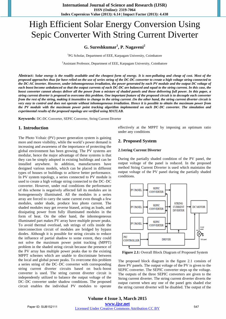
International Journal of Science and Research (IJSR) ISSN (Online): 2319-7064 Index Copernicus Value (2013): 6.14 | Impact Factor (2013): 4.438 Volume 4 Issue 3, March 2015 www.ijsr.net Licensed Under Creative Commons Attribution CC BY High Efficient Solar Energy Conversion Using Sepic Converter With String Current Diverter G. Sureshkumar 1 , P. Nagaveni 2 1 PG Scholar, Department of EEE, Karpagam University, Coimbatore 2 Assistant Professor, Department of EEE, Karpagam University, Coimbatore Abstract: Solar energy is the readily available and the cheapest form of energy. It is non-polluting and cheap of cost. Most of the proposed approaches thus far have relied on the use of series string of the DC-DC converter to create a high voltage string connected to the DC-AC inverter. However, under inhomogeneous irradiation, the power generated by each PV module and the output DC voltage of each boost become unbalanced so that the output currents of each DC-DC are balanced and equal to the string current. In this case, the boost converter cannot always deliver all the power from a mixture of shaded panels and those delivering full power. In this paper, a string current diverter is proposed to overcome this problem. One important feature of the proposed circuit is to decouple each converter from the rest of the string, making it insensitive to change in the string current .On the other hand, the string current diverter circuit is very easy to control and does not operate without inhomogeneous irradiation. Hence it is possible to obtain the maximum power from the PV module with the maximum power point tracking algorithm implemented on each DC-DC converter. The simulation and experimental results of the proposed topology are verified using MATLAB. Keywords: DC-DC Converter, SEPIC Converter, String Current Diverter 1. Introduction The Photo Voltaic (PV) power generation system is gaining more and more visibility, while the world’s power demand is increasing and awareness of the importance of protecting the global environment has been growing. The PV systems are modular, hence the major advantage of these systems is that they can be simply adopted in existing buildings and can be installed anywhere. In addition, manufacturers have designed various models, which can be placed in different types of houses or buildings to achieve better performance. In PV system topology, a series connected to PV module is used to create a high voltage string connected to the DC–DC converter. However, under real conditions the performance of this scheme is negatively affected fall its modules are in homogeneously illuminated. All the modules in a series array are forced to carry the same current even though a few modules, under shade, produce less photo current. The shaded modules may get reverse biased, acting as loads, and dissipating power from fully illuminated modules in the form of heat. On the other hand, the inhomogeneous illuminated part makes PV array have multiple power peaks. To avoid thermal overload, sub strings of cells inside the interconnection circuit of modules are bridged by bypass diodes. Although it is possible for string circuits to reduce the influence of partial shadow to some extent, they could not solve the maximum power point tracking (MPPT) problem in the shaded string circuit because the presence of the PV array has multiple power peaks due to the existing MPPT schemes which are unable to discriminate between the local and global power peaks. To overcome this problem a series string of the DC–DC converter with corresponding string current diverter circuits based on buck–boost converter is used. The string current diverter circuit is independently utilized to balance the output voltage of the DC–DC converter under shadow conditions. The proposed circuit enables the individual PV modules to operate effectively at the MPPT by imposing an optimum ratio under any conditions 2. Proposed System 2.1string Current Diverter During the partially shaded condition of the PV panel, the output voltage of the panel is reduced. In the proposed method String Current Diverter is used which maintains the output voltage of the PV panel during the partially shaded conditions. Figure 2.1: Overall Block Diagram of Proposed System The proposed block diagram in the figure 2.1 consists of three PV panels. The output voltage of the PV is given to the SEPIC converter. The SEPIC converter steps up the voltage. The outputs of the three SEPIC converters are given to the String current diverter. The string current diverter diverts the output current when any one of the panel gets shaded else the string current diverter will be disabled. The output of the Paper ID: SUB152111 547
Transcript of High Efficient Solar Energy Conversion Using Sepic ...
International Journal of Science and Research (IJSR) ISSN (Online): 2319-7064
Index Copernicus Value (2013): 6.14 | Impact Factor (2013): 4.438
Volume 4 Issue 3, March 2015
www.ijsr.net Licensed Under Creative Commons Attribution CC BY
High Efficient Solar Energy Conversion Using
Sepic Converter With String Current Diverter
G. Sureshkumar1, P. Nagaveni
2
1PG Scholar, Department of EEE, Karpagam University, Coimbatore
2Assistant Professor, Department of EEE, Karpagam University, Coimbatore
Abstract: Solar energy is the readily available and the cheapest form of energy. It is non-polluting and cheap of cost. Most of the
proposed approaches thus far have relied on the use of series string of the DC-DC converter to create a high voltage string connected to
the DC-AC inverter. However, under inhomogeneous irradiation, the power generated by each PV module and the output DC voltage of
each boost become unbalanced so that the output currents of each DC-DC are balanced and equal to the string current. In this case, the
boost converter cannot always deliver all the power from a mixture of shaded panels and those delivering full power. In this paper, a
string current diverter is proposed to overcome this problem. One important feature of the proposed circuit is to decouple each converter
from the rest of the string, making it insensitive to change in the string current .On the other hand, the string current diverter circuit is
very easy to control and does not operate without inhomogeneous irradiation. Hence it is possible to obtain the maximum power from
the PV module with the maximum power point tracking algorithm implemented on each DC-DC converter. The simulation and
experimental results of the proposed topology are verified using MATLAB.
Keywords: DC-DC Converter, SEPIC Converter, String Current Diverter
1. Introduction
The Photo Voltaic (PV) power generation system is gaining
more and more visibility, while the world’s power demand is
increasing and awareness of the importance of protecting the
global environment has been growing. The PV systems are
modular, hence the major advantage of these systems is that
they can be simply adopted in existing buildings and can be
installed anywhere. In addition, manufacturers have
designed various models, which can be placed in different
types of houses or buildings to achieve better performance.
In PV system topology, a series connected to PV module is
used to create a high voltage string connected to the DC–DC
converter. However, under real conditions the performance
of this scheme is negatively affected fall its modules are in
homogeneously illuminated. All the modules in a series
array are forced to carry the same current even though a few
modules, under shade, produce less photo current. The
shaded modules may get reverse biased, acting as loads, and
dissipating power from fully illuminated modules in the
form of heat. On the other hand, the inhomogeneous
illuminated part makes PV array have multiple power peaks. To avoid thermal overload, sub strings of cells inside the
interconnection circuit of modules are bridged by bypass
diodes. Although it is possible for string circuits to reduce
the influence of partial shadow to some extent, they could
not solve the maximum power point tracking (MPPT)
problem in the shaded string circuit because the presence of
the PV array has multiple power peaks due to the existing
MPPT schemes which are unable to discriminate between
the local and global power peaks. To overcome this problem
a series string of the DC–DC converter with corresponding
string current diverter circuits based on buck–boost
converter is used. The string current diverter circuit is
independently utilized to balance the output voltage of the
DC–DC converter under shadow conditions. The proposed
circuit enables the individual PV modules to operate
effectively at the MPPT by imposing an optimum ratio
under any conditions
2. Proposed System
2.1string Current Diverter
During the partially shaded condition of the PV panel, the
output voltage of the panel is reduced. In the proposed
method String Current Diverter is used which maintains the
output voltage of the PV panel during the partially shaded
conditions.
Figure 2.1: Overall Block Diagram of Proposed System
The proposed block diagram in the figure 2.1 consists of
three PV panels. The output voltage of the PV is given to the
SEPIC converter. The SEPIC converter steps up the voltage.
The outputs of the three SEPIC converters are given to the
String current diverter. The string current diverter diverts the
output current when any one of the panel gets shaded else
the string current diverter will be disabled. The output of the
Paper ID: SUB152111 547

International Journal of Science and Research (IJSR) ISSN (Online): 2319-7064
Index Copernicus Value (2013): 6.14 | Impact Factor (2013): 4.438
Volume 4 Issue 3, March 2015
www.ijsr.net Licensed Under Creative Commons Attribution CC BY
string current diverter is given to the DC motor in which the
speed is controlled using Armature control method.
2.2 String Current Diverter
String current diverters provide a means to diverting the
output currents of boost converters away from the unshaded
PV module to the next module in the string. This allows the
rest of the shaded modules to operate at the maximum power
point voltage. The current diverter shown in the figure 2.2 is
made of diverter modules connected across each pair of PV
modules. Each diverter module consists of a switch pair
(MOSFETs) in addition to an energy storage element L. The
maximum value of the inductance current corresponds to the
short circuit current (Isc) of a PV module. This most
unfavourable case occurs when two consecutive PV modules
receive extreme levels of irradiation, namely G = 1000
W/m2 for one and 0W/m2for the other. The diverter module
along with the corresponding two PV modules forms a half
bridge converter feeding an inductive load. During normal
climatic conditions, the diverter modules are disabled and
the string current flows serially through all output capacitors
of the boost converters. When one or more PV modules are
shaded, the corresponding current diverter is able to divert
the string current. The string current diverter is switched ON
or OFF according to balance or imbalance of output currents
of PV modules. With the existing measures of output
currents of PV modules, an error calculation is carried out
and compared with a threshold value ε with the following
method ΔIPV = |IPVN−1− IPV| ≥ ε and then the SCD is
switched ON or OFF. The value of ε is chosen different
from zero to take into account the characteristic dispersions
of PV modules and to leave light imbalances that are not
harmful. For NPV modules, the number of active switches S
(MOSFET T and diode D) is 2N−2 while the number of
inductor is N−1. During operation, the diverter circuit
provides equalization by directing energy from the un
shaded PV converter to the shaded PV converter. It aims at
keeping the output voltage constant under normal or shaded
conditions .To simplify the analysis, we consider the case of
only three PV modules. For example, if PV2 module is
shaded, the MOSFET T4 is turned ON. As a result, the filter
inductor current increases linearly and the energy is stored in
the inductor L2 .When the switch is turned OFF, the energy
stored in the inductor is delivered (D3 turned ON) to the
output capacitor of the boost converter connected to the
PV2. As a result, the inductor current decreases in a linear
fashion. If the energy stored in the inductor L2 is completely
transferred to capacitorC2 and the MOSFET T3 is still
turned ON, the current changes directions.
Figure 2.2: String Current Diverter
Then, when MOSFET T4 is turned ON, the diode D4
transfers the energy stored in the inductor L2 to the capacitor
C3. First, the MOSFET T4 is turned ON. As a result, the
filter inductor current increases linearly and the energy is
stored in the inductor L2. When the switch is turned OFF,
the energy stored in the inductor is delivered (D3 turned
ON) to the output capacitor of the boost converter connected
to the PV2. As a result, the inductor current decreases in a
linear fashion. If the energy stored in the inductor L2 is
completely transferred to capacitor C2 and the MOSFET T3
is still turned ON, the current changes directions. Then,
when MOSFET T4 is turned ON, the diode D4 transfers the
energy stored in the inductor L2 to the capacitor C3.
2.3 SEPIC Conveter
The buckboost feature of the SEPIC widens the applicable
PV voltage and thus increases the adopted PV module
flexibility. Among all the available converters, SEPIC has
the merits of non-inverting polarity, easy to drive switch,
and low input current pulsating for high precise MPPT that
makes its integral characteristics suitable for the low power
PV charger system. SEPIC converter can raise the output
voltage to a suitable range, and can supply an isolation route
to isolate the input and output terminal after terminate
charging. But this circuit has two disadvantages; one is low
efficiency and the other needs two inductors. The efficiency
is not the major factor when charger is designed and use of
coupling inductor solves the other disadvantage. Therefore
the SEPIC is a good choice for constant current converter
design.
Paper ID: SUB152111 548

International Journal of Science and Research (IJSR) ISSN (Online): 2319-7064
Index Copernicus Value (2013): 6.14 | Impact Factor (2013): 4.438
Volume 4 Issue 3, March 2015
www.ijsr.net Licensed Under Creative Commons Attribution CC BY
The SEPIC converter is shown in the figure 2.3
Figure 2.3: SEPIC converter
The operation principle of SEPIC is: when S turns ON, the
input source stores energy in the inductor L1. The inductor
current increases linearly. The energy stores in capacitor C1
will transfer into inductor L2. The energy for the load is
supplied by capacitor C2.When S turns OFF, the energy
stored in inductor L1 transfer to C1. The energy stored in L2
will transfer to C2 through Diode and supplying the energy
to loading.
2.4 Pv Panel
The MonocrystallinePV panels are used. 40 cells are
connected in series to form a single module. Voltage of
single cell is 0.6V so the voltage of a single module is 24V.
In this proposed method 3 modules are used.
2.4 MPPT (incremental conductance)
The incremental conductance algorithm is based on the fact
that the slope of the curve power vs. voltage (current) of the
PV module is zero at the MPP, positive (negative) on the left
of it and negative (positive) on the right, as can be seen in
the figure 2.4
∆V/∆P= 0 (∆I/∆P) at the MPP
∆V/∆P< 0(∆I/∆P) on the left
∆V/∆P> 0(∆I/∆P) on the right
By comparing the increment of the power vs. the increment
of the voltage (current) between two consecutives samples,
the change in the MPP voltage can be determined. A scheme
of the algorithm is shown in the figure 2.4
Figure 2.4: Incremental conductance algorithm
2.5 Speed Control In Dc Motor
Separately excited dc motor is used in this proposed method.
In separately excited dc motor the speed is controlled using
armature control. In armature control the output speed of dc
motor is compared with the reference speed and by varying
the input voltage to the motor the speed is controlled.
3. Simulation Circuit
3.1 Simulation Diagram Of Proposed System
The simulation block diagram of proposed system is shown
in the figure 3.1. It consists of three solar panels. The output
of each solar panel is given to individual SEPIC converter in
which the MPPT is tracked using Incremental Conductance
Algorithm. The outputs of the SEPIC converter are given to
the string current diverter which diverters the current when
the panel gets partially shaded and provides a constant
output voltage. This is given to the dc motor in which the
speed is controlled using armature control method using PI
controller.
Figure 3.1: Simulation diagram of proposed method
Paper ID: SUB152111 549

International Journal of Science and Research (IJSR) ISSN (Online): 2319-7064
Index Copernicus Value (2013): 6.14 | Impact Factor (2013): 4.438
Volume 4 Issue 3, March 2015
www.ijsr.net Licensed Under Creative Commons Attribution CC BY
3.2 Simulation Diagram of PV Panel
The subsystem of PV panel is shown in the figure 3.2 the
solar cell is a physical system it cannot be directly connected
to the Simulink model so a converter is used in between
them to connect the two systems.
Figure 3.2: Subsystem of PV panel
3.3 Simulation Diagram Of MPPT Techniques
The simulation diagram of MPPT technique is show in the
figure 3.3 In the proposed method Incremental Conductance
Algorithm is used to track the MPPT. In this MPPT the
maximum power is tracked by comparing the previous value
of voltage, current and power with the recent values and the
duty cycle is given accordingly.
Figure 3.3: Simulation diagram of MPPT technique
3.4 Simulation Diagram of SEPIC Converter
The simulation diagram of SEPIC converter is shown in the
figure 3.4. The SEPIC converter is Single Ended Primary
Inductance Converter. It either steps up or steps down the
voltage based on the turn on and off of IGBT.
Figure 3.4: Simulation diagram of SEPIC converter
3.5 Simulation Diagram of String Current Diverter
The simulation diagram of String Current Diverter is shown
in the figure 3.5 The String Current Diverter diverters back
the output current of the DC-DC converter in order to
maintain the output voltage of the DC-DC converters
constant. String current diverter is switched ON or OFF
according to balance or imbalance of output currents of PV
modules. With the existing measures of output currents of
PV modules, an error calculation is carried out and
compared with a threshold value ε and the SCD is switched
ON or OFF accordingly.
Figure 3.5: Simulation diagram of String Current Diverter
3.6 Simulation Diagram of Speed Control of Dc Motor
Speed control simulation diagram is shown in the figure.
Here the actual speed is compared with the set reference and
the error response is given to the PI controller. The PI
controller produces the required response which is compared
with the carrier waveform and the gating pulses are
produced accordingly. The gating pulses turn on and off the
IGBT which controls the Armature Voltage of the DC
motor.
Thus here the speed is controlled by varying the armature
voltage.
Figure 3.6: Simulation diagram of speed control of dc motor
Paper ID: SUB152111 550

International Journal of Science and Research (IJSR) ISSN (Online): 2319-7064
Index Copernicus Value (2013): 6.14 | Impact Factor (2013): 4.438
Volume 4 Issue 3, March 2015
www.ijsr.net Licensed Under Creative Commons Attribution CC BY
4. Simulation Result
The output current of PV panel is shown in the figure 4.1
Figure 4.1: PV panel current
(X-axis 1 div=0.5s Y-axis 1 div=1 A)
The output voltage of SEPIC converter is shown in the
figure 4.2
Figure 4.2: SEPIC converter voltage
(X-axis 1 div= 0.5s, Y-axis 1 div=20 V)
The output current of SEPIC converter is shown in Figure
4.3
Figure 4.3: SEPIC converter current
(X-axis 1 div=0.5s, Y-axis 1 div=10A)
The output voltage of SEPIC converter is shown in Figure
4.4
Figure 4: 4String Current Diverter Voltage
(X-axis 1 div=0.5s, Y-axis 1 div=50V)
The speed control of the dc motor is shown in the figure 4.5
Speed response of dc motor
(X-axis 1 div=0.5 s, Y-axis 1 div=500rpm)
5. Conclusion
Thus the performance of cascaded DC–DC converter
topology under shaded conditions, this paper proposes a
string current diverter connected to each SEPIC converter.
During normal climatic conditions, the diverter modules are
disabled and the string current flows serially through all
output capacitors of SEPIC converters. When one or more
PV modules are shaded, the corresponding current diverter
is able to divert the string current. The detection of shaded
PV modules is carried out simply by the comparison of the
output currents of PV modules without any addition of
sensors. This circuit is able to successfully decouple each
converter from the rest of the string, making it insensitive to
shading conditions. Moreover, the presented topology
enables effective application of the algorithms of MPPT
under shaded conditions. The MATLAB simulation and
experimental results verify that the proposed topology
exhibits good performance under inhomogeneous and
homogeneous irradiations.
References
[1] Anna Fay W (1986), ‘The Handbook of Photovoltaic
Applications: Building Applications and System Design
Considerations’. Atlanta, GA: Fairmont Press.
[2] F. Blaabjerg, Z. Chen, and S. B. Kjaer (2004), ‘Power
electronics as efficient interface in dispersed power
generation Systems’, IEEE Trans. Power Electron., vol.
Paper ID: SUB152111 551

International Journal of Science and Research (IJSR) ISSN (Online): 2319-7064
Index Copernicus Value (2013): 6.14 | Impact Factor (2013): 4.438
Volume 4 Issue 3, March 2015
www.ijsr.net Licensed Under Creative Commons Attribution CC BY
19, no. 5, pp. 1184–1194.
[3] Bratcu, I. Munteanu, S. Bacha, D. Picault, and B.
Raison (2009), ‘Power optimization strategy for
cascaded DC–DC converter architectures of
photovoltaic modules’, in Proc. IEEE Int. Conf. Ind.
Technol., Churchill, Victoria, Australia, pp. 1–8.
[4] R. W. Erickson and D. Maksimovic (1997),
‘Fundamentals of Power Electronics’. New York:
Chapman & Hall.
[5] T. Esram and P. L. Chapman (2007), ‘Comparison of
photovoltaic array maximum power point tracking
techniques’, IEEE Trans. Energy Convers., vol. 22, no.
2, PP 439–449.
[6] L. Gao, R. A. Dougal, S. Liu, and A. P. Iotova (2009),
‘Parallel-connected solar PV system to address partial
and rapidly fluctuating shadow conditions’, IEEE Trans.
Ind. Electron., vol. 56, no. 5, pp. 1548–1556.
[7] R. Gonzalez, J. Lopez, P. Sanchis, and L. Marroyo
(2007), ‘Transformerless inverter for single-phase
photovoltaic systems’, IEEE Trans. Power Electron.,
vol. 22, no. 2, pp. 693–697.
[8] M.Kolhe (2009), ‘Techno-economic optimum sizing of
a stand-alone solar photovoltaic system’, IEEE Trans.
Energy Convers., vol. 24, no. 2, pp. 511–519.
[9] L. Linares, R. W. Erickson, S. MacAlpine, and M.
Brandemuehl (2009), ‘Improved energy capture in
series string photovoltaics via smart distributed power
electronics’, in Proc. IEEE Appl. Power Electron., Conf,
pp 904–910.
[10] Y.Li, X.Raun, D. Yang, F. Liu, and C. Tse (2010),
‘Synthesis of multiple input DC-DC converters’, IEEE
Trans. Power Electron., vol. 25, no. 9,pp. 2372–2385
Paper ID: SUB152111 552