High-efficiency, multi-edge cast iron machining cutterMFK · 1 MFK Multi-edge cutter achieves...
6
High-efficiency Multi-edge Cutter for Cast Iron High-efficiency, multi-edge cast iron machining cutter MFK • Reduces chattering, achieving a superior surface finish • 10-cornered pentagonal inserts for stable and economical machining • Two special insert structures reduce cutting force and improve edge strength • Multi-edge design is ideal for high- efficiency and high-feed cast iron machining New CVD-grade CA420M for longer tool life Wiper insert for finishing is available Milling MFK
-
Upload
truongkiet -
Category
Documents
-
view
216 -
download
0
Transcript of High-efficiency, multi-edge cast iron machining cutterMFK · 1 MFK Multi-edge cutter achieves...
High-efficiency Multi-edge Cutter for Cast Iron
High-efficiency, multi-edge cast iron machining cutter
MFK• Reduces chattering, achieving a superior surface finish
• 10-cornered pentagonal inserts for stable and economical machining
• Two special insert structures reduce cutting force and improve edge strength
• Multi-edge design is ideal for high-efficiency and high-feed cast iron machining
Reduces chattering and maintains sharpness even using negative type of insert
New CVD-grade CA420M for longer tool life
Wiper insert for finishing is available
Milling MFK
1
MFKMulti-edge cutter achieves high-efficiency cast iron machining10-cornered pentagonal inserts for stable and economical machining
MFK Competitor ASharp cutting prevents
burr formation
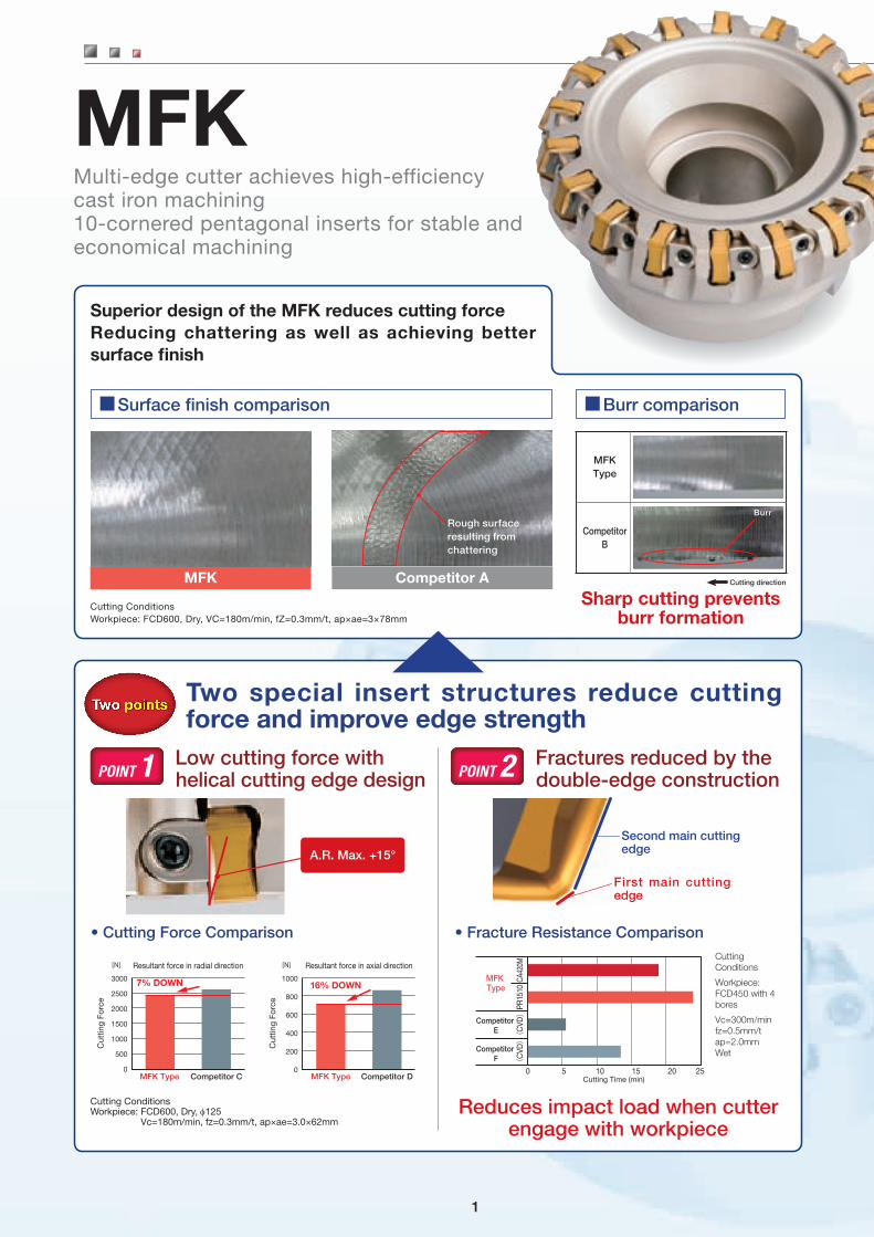
Superior design of the MFK reduces cutting forceReducing chattering as well as achieving better surface finish
Two special insert structures reduce cutting force and improve edge strength
Low cutting force with helical cutting edge designPOINT 1 Fractures reduced by the
double-edge constructionPOINT 2
■Surface finish comparison ■Burr comparison
Cutting ConditionsWorkpiece: FCD600, Dry, VC=180m/min, fZ=0.3mm/t, ap×ae=3×78mm
Cutting Conditions
Workpiece: FCD450 with 4 bores
Vc=300m/min fz=0.5mm/t ap=2.0mm Wet
Cutting ConditionsWorkpiece: FCD600, Dry, f125
Vc=180m/min, fz=0.3mm/t, ap×ae=3.0×62mm
• Cutting Force Comparison
Reduces impact load when cutter engage with workpiece
• Fracture Resistance Comparison
Two points
MFK Type
Resultant force in radial direction Resultant force in axial direction
3000
2500
2000
1500
1000
500
0
[N] [N]
Cut
ting
Forc
e
Cut
ting
Forc
e
1000
800
600
400
200
0
7% DOWN 16% DOWN
Competitor C MFK Type Competitor D0 5 10
Cutting Time (min)
CA42
0MPR
1510
(C
VD)
(C
VD)
Competitor E
Competitor F
MFK Type
15 20 25
MFK Type
Competitor B
Cutting direction
BurrRough surface resulting from chattering
Second main cutting edge
First main cutting edge
A.R. Max. +15°
2
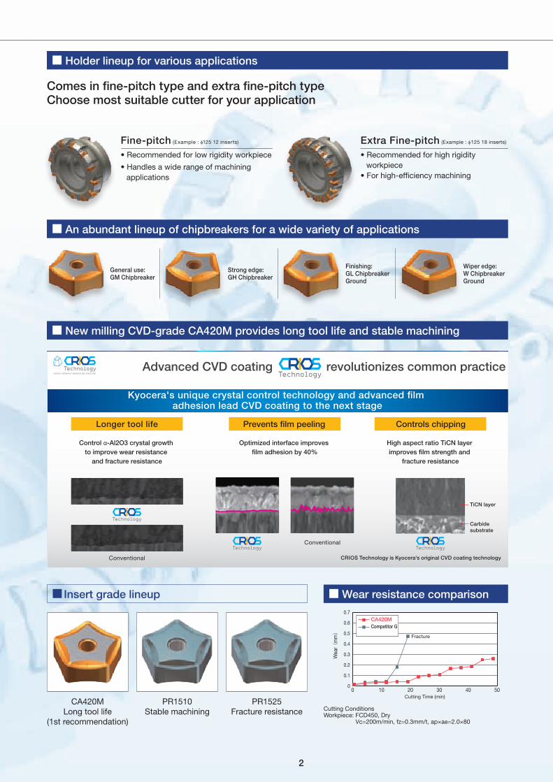
■ Insert grade lineup
Comes in fine-pitch type and extra fine-pitch typeChoose most suitable cutter for your application
CRIOS Technology is Kyocera's original CVD coating technologyConventional
Conventional
Kyocera's unique crystal control technology and advanced film adhesion lead CVD coating to the next stage
Advanced CVD coating revolutionizes common practice
Longer tool life Prevents film peeling Controls chipping
Carbide substrate
TiCN layer
Control α-Al2O3 crystal growth to improve wear resistance
and fracture resistance
Optimized interface improves film adhesion by 40%
High aspect ratio TiCN layer improves film strength and
fracture resistance
■ Holder lineup for various applications
■ An abundant lineup of chipbreakers for a wide variety of applications
■ New milling CVD-grade CA420M provides long tool life and stable machining
■ Wear resistance comparison
General use: GM Chipbreaker
Finishing: GL ChipbreakerGround
Strong edge: GH Chipbreaker
Wiper edge: W ChipbreakerGround
0 10 20 30 40 50
0.7
0.6
0.5
0.4
0.3
0.2
0.1
0
Cutting Time (min)
Fracture
Wea
r (m
m)
CA420MCompetitor G
Cutting ConditionsWorkpiece: FCD450, Dry
Vc=200m/min, fz=0.3mm/t, ap×ae=2.0×80
Fine-pitch (Example : f125 12 inserts)
• Recommended for low rigidity workpiece
• Handles a wide range of machining applications
Extra Fine-pitch (Example : f125 18 inserts)
• Recommended for high rigidity workpiece
• For high-efficiency machining
CA420M Long tool life
(1st recommendation)
PR1510 Stable machining
PR1525 Fracture resistance

3
MFK
■ MFK Face Mill
Fig.1 Fig.2
Fig.3 Fig.4
φ C φ D1φ D
S
G
φ d4
φ d3b
aE
φ d
H
φ D1φ D
S
φ d1
φ d
b
aE
H
φ D1φ Dφ d2
φ d1
φ dφ D2 φ D2
b
aE
S
H
φ D1
φ DC1C
S
φ d6
φ d5
φ d4
φ d3
G
b
aE
φ d
H
φ d1
φ d1
70
70
7070
φ D2 φ D2
Rake Angle (°)
Description A.R. R.R.
MFK080R-
(MAX.)+15°
-7°
MFK100R- -6°
MFK125R-
…
MFK315R--5°
Spare Parts and Applicable Inserts
Description
Spare Parts
Applicable Inserts Description
Spare Parts
Applicable Inserts
Wedge Wedge screw
Wrench Mounting Bolt
Wedge Wedge screw
Wrench Mounting Bolt
MFK 080R-11-8T
C09N W6X18N TT-15
HH16X40
PNMG1106XNEN-GMPNMG1106XNEN-GHPNEG1106XNEN-GLPNEG1106XNER-W
MFK 080R-11-8T-M
C09N W6X18N TT-15
HH12X35
PNMG1106XNEN-GMPNMG1106XNEN-GHPNEG1106XNEN-GLPNEG1106XNER-W
100R-11-10T 100R-11-10T-M HH16X40
125R-11-12T
–
125R-11-12T-M
–
160R-11-16T 160R-11-16T-M
200R-11-20T 200R-11-20T-M
250R-11-24T 250R-11-24T-M
315R-11-28T 315R-11-28T-M
MFK 080R-11-10T
C09N W6X18N TT-15
HH16X40
PNMG1106XNEN-GMPNMG1106XNEN-GHPNEG1106XNEN-GLPNEG1106XNER-W
MFK 080R-11-10T-M
C09N W6X18N TT-15
HH12X35
PNMG1106XNEN-GMPNMG1106XNEN-GHPNEG1106XNEN-GLPNEG1106XNER-W
100R-11-14T 100R-11-14T-M HH16X40
125R-11-18T
–
125R-11-18T-M
–
160R-11-22T 160R-11-22T-M
200R-11-28T 200R-11-28T-M
250R-11-36T 250R-11-36T-M315R-11-44T 315R-11-44T-M
Toolholder Dimensions
Bore Dia.
Description StockNo. ofinserts
Dimension (mm)Drawing
Weight (kg)fD fD1 fD2 fd fd1 fd2 H E a b s fd3 fd4 fd5 fd6 fC fC1 G
Inch
Sp
ec
Fin
e-p
itch
MFK 080R-11-8T 8 80 89 7631.75 26 17
63
32 8 12.7
6.0
– –
– –
–
–
–
fig.11.76
100R-11-10T 10 100 109 96 2.98
125R-11-12T 12 125 134100
38.1 55
–
3810 15.9
fig.23.65
160R-11-16T 16 160 169 50.8 70 11 19.1 4.62
200R-11-20T 20 200 209142
47.625 110 40 14 25.4 18 26 101.6 32fig.3
7.65
250R-11-24T 24 250 259 10.73
315R-11-28T MTO 28 315 324 220 22 32 177.8 fig.4 19.71
Ext
ra F
ine-
pitc
h
MFK 080R-11-10T 10 80 89 7631.75 26 17
63
32 8 12.7
6.0
– –
– –
–
–
–
fig.11.70
100R-11-14T 14 100 109 96 2.85
125R-11-18T 18 125 134100
38.1 55
–
3810 15.9
fig.23.44
160R-11-22T 22 160 169 50.8 70 11 19.1 4.44
200R-11-28T 28 200 209142
47.625 110 40 14 25.4 18 26 101.6 32fig.3
7.40
250R-11-36T 36 250 259 10.36
315R-11-44T MTO 44 315 324 220 22 32 177.8 fig.4 19.21
Met
ric
Sp
ec
Fin
e-p
itch
MFK 080R-11-8T-M 8 80 89 76 27 20 13
63
24 7 12.4
6.0
– –
– –
–
–
–fig.1
1.87
100R-11-10T-M 10 100 109 96 32 26 17 28 8 14.4 2.99
125R-11-12T-M 12 125 134100 40
55
–
33 9 16.4 fig.23.56
160R-11-16T-M 16 160 169 70 14 20 66.7 28 4.51
200R-11-20T-M 20 200 209142
60 110 40 14 25.7 18 26 101.6 32fig.3
7.35
250R-11-24T-M 24 250 259 10.43
315R-11-28T-M MTO 28 315 324 220 22 32 177.8 fig.4 19.41
Ext
ra F
ine-
pitc
h
MFK 080R-11-10T-M 10 80 89 76 27 20 13
63
24 7 12.4
6.0
– –
– –
–
–
–fig.1
1.81
100R-11-14T-M 14 100 109 96 32 26 17 28 8 14.4 2.86
125R-11-18T-M 18 125 134100 40
55
–
33 9 16.4 fig.23.38
160R-11-22T-M 22 160 169 70 14 20 66.7 28 4.32
200R-11-28T-M 28 200 209142
60 110 40 14 25.7 18 26 101.6 32fig.3
7.10
250R-11-36T-M 36 250 259 10.07
315R-11-44T-M MTO 44 315 324 220 22 32 177.8 fig.4 18.92
: Std. Item MTO : Made To Order
4
MFK
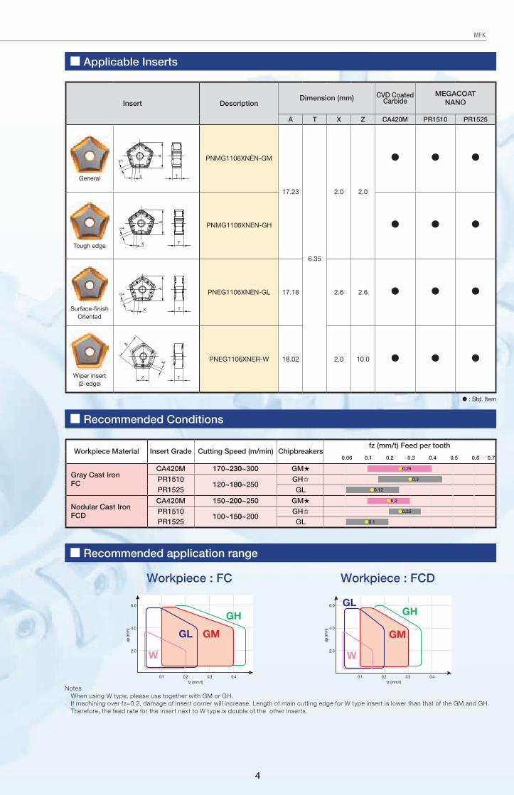
■ Applicable Inserts
■ Recommended Conditions
■ Recommended application range
Insert DescriptionDimension (mm) CVD Coated
CarbideMEGACOAT
NANO
A T X Z CA420M PR1510 PR1525
General
A
X
Z
T
PNMG1106XNEN-GM
17.23
6.35
2.0 2.0
● ● ●
Tough edge
A
X
Z
T
PNMG1106XNEN-GH ● ● ●
Surface-finish Oriented
T
A
X
Z PNEG1106XNEN-GL 17.18 2.6 2.6 ● ● ●
Wiper insert (2-edge)
X
Z
A
T
PNEG1106XNER-W 18.02 2.0 10.0 ● ● ●
Workpiece Material Insert Grade Cutting Speed (m/min) Chipbreakersfz (mm/t) Feed per tooth
0.06 0.1 0.2 0.3 0.4 0.5 0.6 0.7
Gray Cast IronFC
CA420M 170~230~300 GM★ ●0.25
PR1510120~180~250
GH✩ ●0.3
PR1525 GL ●0.12
Nodular Cast IronFCD
CA420M 150~200~250 GM★ ●0.2
PR1510100~150~200
GH✩ ●0.25
PR1525 GL ●0.1
NotesWhen using W type, please use together with GM or GH.If machining over fz=0.2, damage of insert corner will increase. Length of main cutting edge for W type insert is lower than that of the GM and GH.Therefore, the feed rate for the insert next to W type is double of the other inserts.
Workpiece : FC Workpiece : FCD
● : Std. Item
GL GM
W
GH
fz (mm/t)
ap (m
m)
6.0
4.0
2.0
0.1 0.2 0.3 0.4fz (mm/t)
ap (m
m)
GL
GM
W
GH6.0
4.0
2.0
0.1 0.2 0.3 0.4
CP333EN
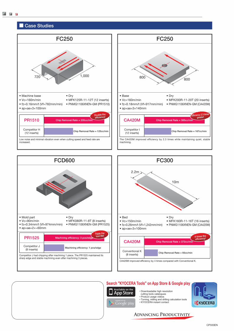
■ Case Studies
FC300
2.2m
10m
• Bed• Vc=150m/min• fz=0.26mm/t (Vf=1,242mm/min)• ap×ae=3×100mm
• Dry• MFK160R-11-16T (16 inserts)• PNMG1106XNEN-GM (CA420M)
CA420M Chip Removal Rate = 372cc/min
4 times the efficiency!
Conventional K (8 inserts)
Chip Removal Rate = 93cc/min
CA420M improved efficiency by 4 times compared with Conventional K.
FC250
720 1,000
• Machine base• Vc=160m/min• fz=0.16mm/t (Vf=782mm/min)• ap×ae=3×100mm
• Dry• MFK125R-11-12T (12 inserts)• PNMG1106XNEN-GM (PR1510)
PR1510 Chip Removal Rate = 235cc/min
Double the efficiency!
Competitor H (12 inserts)
Chip Removal Rate = 125cc/min
Low noise and minimal vibration even when cutting speed and feed rate are increased.
FCD600
• Mold part• Vc=90m/min• fz=0.34mm/t (Vf=974mm/min)• ap×ae=2×~60mm
• Dry• MFK080R-11-8T (8 inserts)• PNMG1106XNEN-GM (PR1525)
PR1525 Machining efficiency: 3 pcs/edge
Triple the tool life!
Competitor J (8 inserts)
Machining efficiency: 1 pcs/edge
Competitor J had chipping after machining 1 piece. The PR1525 maintained its sharp edge and stable machining even after machining 3 pieces.
FC250
800 800
• Base• Vc=160m/min• fz=0.18mm/t (Vf=917mm/min)• ap×ae=3×140mm
• Dry• MFK200R-11-20T (20 inserts)• PNMG1106XNEN-GM (CA420M)
CA420M Chip Removal Rate = 385cc/min
Efficiency 2.3 times greater!
Competitor I (12 inserts)
Chip Removal Rate = 167cc/min
The CA420M improved efficiency by 2.3 times while maintaining quiet, stable machining.