
High Efficiency, Low EMI and Positioning Tolerant … · Redesign receiver and charger coil; design...
26
High Efficiency, Low EMI and Positioning Tolerant Wireless Charging of EVs Project ID: VS102 2016 DOE Vehicle Technologies Program Annual Merit Review and Peer Evaluation Meeting Principal Investigator Rakan Chabaan Senior Research Engineer Hyundai America Technical Center Inc (HATCI) 8 April, 2016 This presentation does not contain any proprietary, confidential, or otherwise restricted information
Transcript of High Efficiency, Low EMI and Positioning Tolerant … · Redesign receiver and charger coil; design...

High Efficiency, Low EMI and Positioning TolerantWireless Charging of EVs
Project ID: VS102
2016 DOE Vehicle Technologies Program Annual Merit Review and Peer Evaluation Meeting
Principal InvestigatorRakan Chabaan
Senior Research EngineerHyundai America Technical Center Inc (HATCI)
8 April, 2016
This presentation does not contain any proprietary, confidential, or otherwise restricted information
2
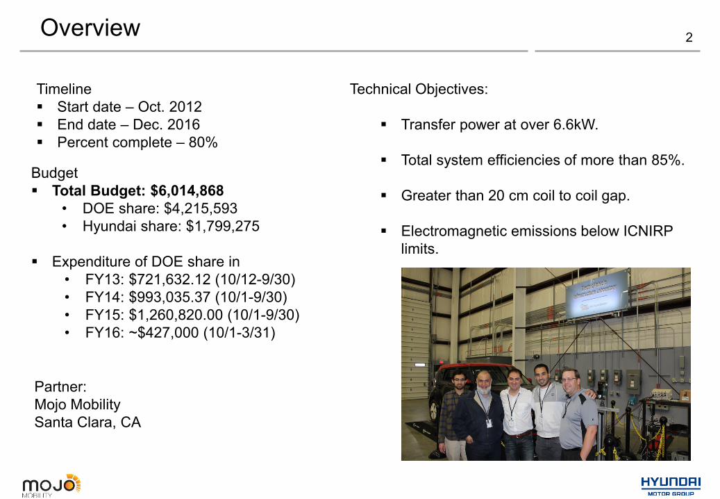
Timeline Start date – Oct. 2012 End date – Dec. 2016 Percent complete – 80%
Overview
Budget Total Budget: $6,014,868
• DOE share: $4,215,593• Hyundai share: $1,799,275
Expenditure of DOE share in• FY13: $721,632.12 (10/12-9/30)• FY14: $993,035.37 (10/1-9/30)• FY15: $1,260,820.00 (10/1-9/30)• FY16: ~$427,000 (10/1-3/31)
Technical Objectives:
Transfer power at over 6.6kW.
Total system efficiencies of more than 85%.
Greater than 20 cm coil to coil gap.
Electromagnetic emissions below ICNIRP limits.
Partner:Mojo MobilitySanta Clara, CA
3Milestones
Month/Year
Milestone or Go/No-Go Decision
Description Status
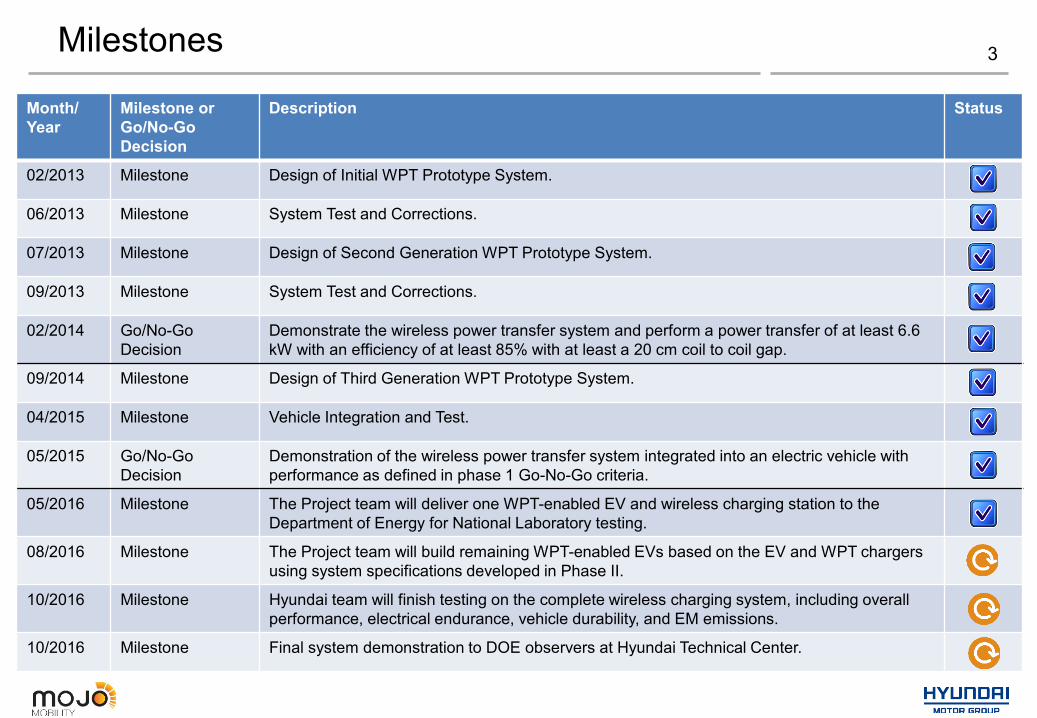
02/2013 Milestone Design of Initial WPT Prototype System.
06/2013 Milestone System Test and Corrections.
07/2013 Milestone Design of Second Generation WPT Prototype System.
09/2013 Milestone System Test and Corrections.
02/2014 Go/No-Go Decision
Demonstrate the wireless power transfer system and perform a power transfer of at least 6.6 kW with an efficiency of at least 85% with at least a 20 cm coil to coil gap.
09/2014 Milestone Design of Third Generation WPT Prototype System.
04/2015 Milestone Vehicle Integration and Test.
05/2015 Go/No-Go Decision
Demonstration of the wireless power transfer system integrated into an electric vehicle with performance as defined in phase 1 Go-No-Go criteria.
05/2016 Milestone The Project team will deliver one WPT-enabled EV and wireless charging station to the Department of Energy for National Laboratory testing.
08/2016 Milestone The Project team will build remaining WPT-enabled EVs based on the EV and WPT chargers using system specifications developed in Phase II.
10/2016 Milestone Hyundai team will finish testing on the complete wireless charging system, including overall performance, electrical endurance, vehicle durability, and EM emissions.
10/2016 Milestone Final system demonstration to DOE observers at Hyundai Technical Center.
System Overview 4
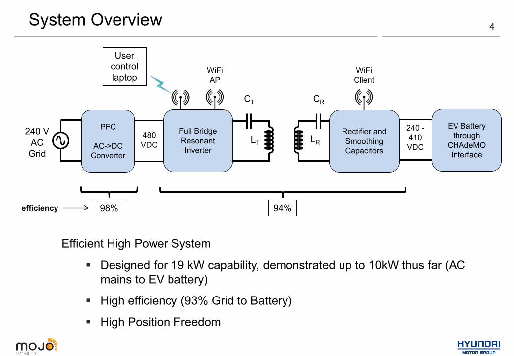
Efficient High Power System
Designed for 19 kW capability, demonstrated up to 10kW thus far (AC mains to EV battery)
High efficiency (93% Grid to Battery)
High Position Freedom
WiFiAP
240 -410 VDC
PFC
AC->DC Converter
240 VACGrid
480 VDC
Full Bridge Resonant Inverter
CT
LT
CR
LRRectifier and Smoothing Capacitors
EV Battery through
CHAdeMOInterface
WiFiClient
User control laptop
94%efficiency 98%
5
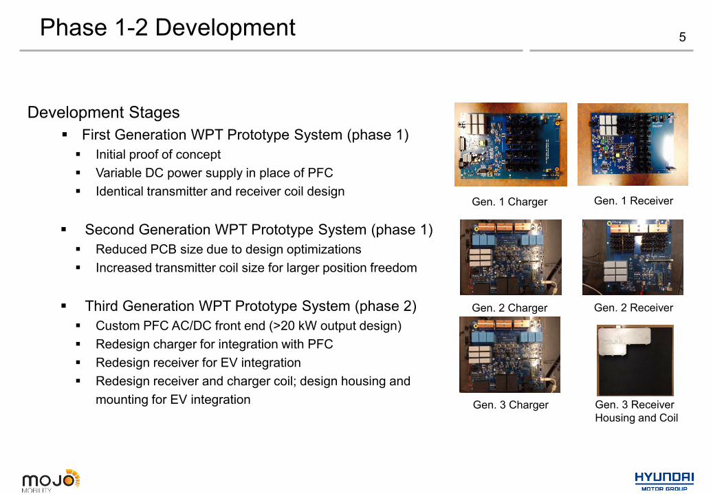
Development Stages First Generation WPT Prototype System (phase 1) Initial proof of concept Variable DC power supply in place of PFC Identical transmitter and receiver coil design
Second Generation WPT Prototype System (phase 1) Reduced PCB size due to design optimizations Increased transmitter coil size for larger position freedom
Third Generation WPT Prototype System (phase 2) Custom PFC AC/DC front end (>20 kW output design) Redesign charger for integration with PFC Redesign receiver for EV integration Redesign receiver and charger coil; design housing and
mounting for EV integration
Phase 1-2 Development
Gen. 1 Receiver
Gen. 2 Receiver
Gen. 1 Charger
Gen. 2 Charger
Gen. 3 Receiver Housing and Coil
Gen. 3 Charger

6
Phase 3 New design necessary in phase 3 to fix issues found in
phase 2; also includes design improvements for safe testing, and cost reduction.
A. New PFC (Gen. 2) Fixed design issue with Gen. 1, inductors saturated at high
current.B. New Tx (Gen. 4 Charger) New gate drivers and FET design result in improved
safety/protection, and better thermal management Uses a second WiFi connection to connect to user control
laptop.
C. Receiver (Gen. 3 from Phase 2) Used same design as Phase 2, except using lower cost Ferrite
(1/10 cost from new source), with same performance as before
Phase 3 Development
Gen. 3 Receiver Housing and CoilGen. 4 Charger
Gen. 2 PFC

Tx and Rx Assembly 7
Receiver800mm x 740mm
Transmitter920mm x 1180mm
Transmitter assembly includes coil and capacitors.Receiver assembly includes coil, and electronics housing with capacitors and rectifier.
High voltage output
Diagnostics (voltage measurement and CAN bus)
12V power input
CHAdeMO interface wires

8
240 V AC input to 480 V DC output Designed for > 20 kW output 0.9998 Power Factor
Interleaved 4 phase operation Reduced current through each switch Reduced output ripple of PFC
Single Board construction (60x40x12 cm) Record Efficiencies
High Efficiency (98.3%) AC/DC Power Factor Correction (PFC) front end:
Phase 3 Development
Top View of PFC

9Phase 3 Development
In Summary, we have decreased size of Tx coil in Phase 2; maintained size in Phase 3 Results in 3% efficiency increase Smaller X-Y positioning, but sufficient for most applications (> ±20 cm)
Output power limited by electronic load. Higher powers can be reached with 2 loads inseries.
80
85
90
95
100
0 2000 4000 6000 8000 10000
Output Power (W)
DC-D
C Ef
ficie
ncy
(%)
Phase 1 Phase 2 & 3
10Phase 3 Development
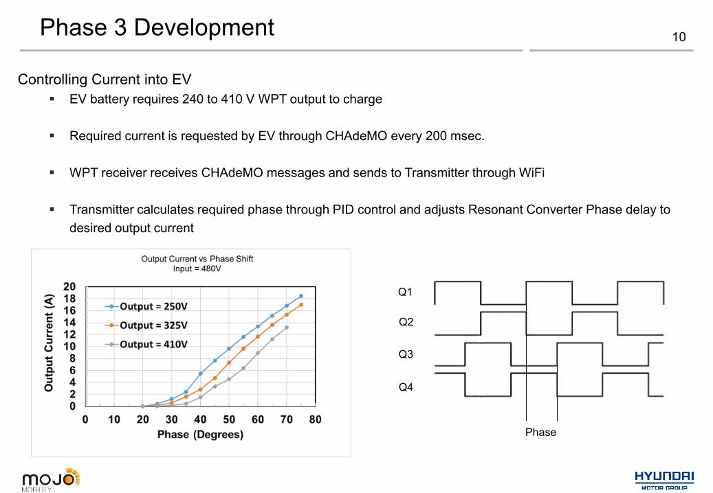
Controlling Current into EV EV battery requires 240 to 410 V WPT output to charge
Required current is requested by EV through CHAdeMO every 200 msec.
WPT receiver receives CHAdeMO messages and sends to Transmitter through WiFi
Transmitter calculates required phase through PID control and adjusts Resonant Converter Phase delay todesired output current
Q1
Q2
Q3
Q4
Phase

11
Conditions: 87kHz switching frequency 20cm coil to coil separation 5kW input power
Notes: Phase 2&3 utilize a smaller coil design
Phase 3 Development
X Offset
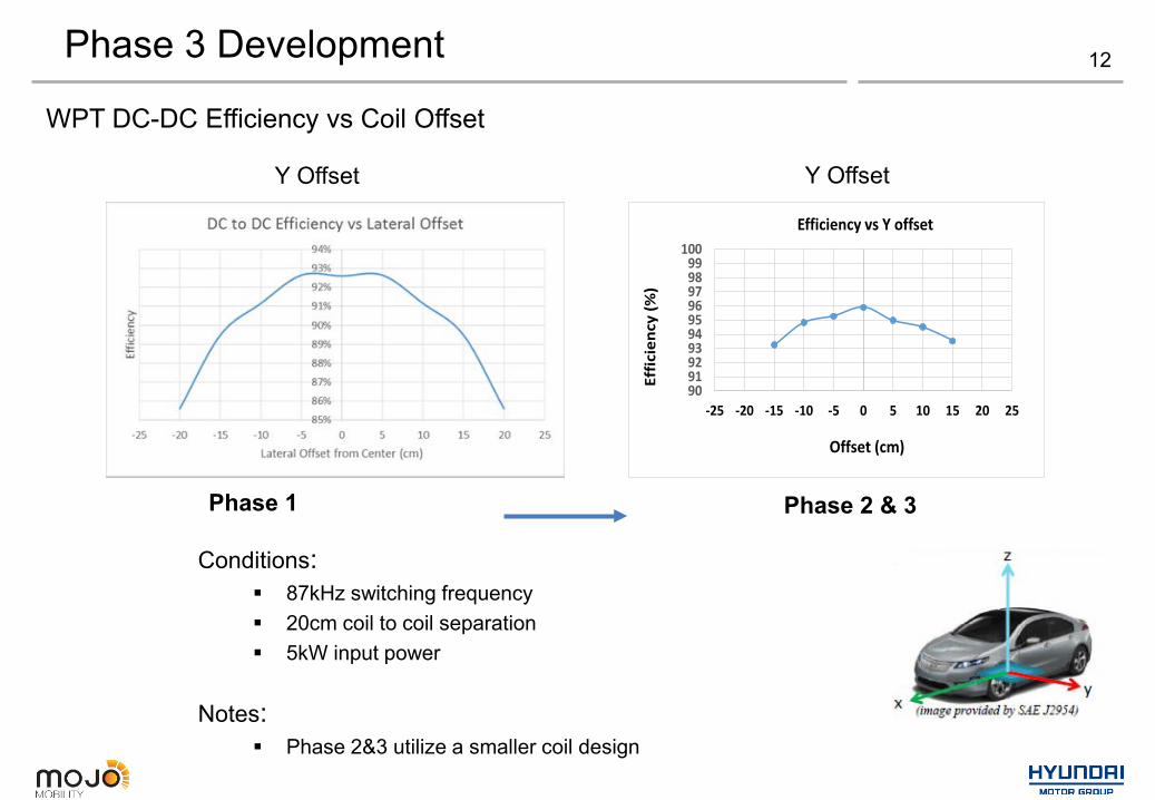
WPT DC-DC Efficiency vs Coil Offset
90919293949596979899
100
-25 -20 -15 -10 -5 0 5 10 15 20 25
Efficiency vs X Offset
Effic
ienc
y(%
)
Offset (cm)
Phase 1 Phase 2 & 3
X Offset
12Phase 3 Development
90919293949596979899
100
-25 -20 -15 -10 -5 0 5 10 15 20 25
Efficiency vs Y offset
Offset (cm)
Effic
ienc
y(%
)
Y Offset Y Offset
Phase 1 Phase 2 & 3
WPT DC-DC Efficiency vs Coil Offset
Conditions: 87kHz switching frequency 20cm coil to coil separation 5kW input power
Notes: Phase 2&3 utilize a smaller coil design

13Phase 3 Development - User Interface SoftwareUser chooses operating mode
Configurable fields to control the power
• User interface software (UI) runs on PC laptop and connects to Tx through PC WiFiControls all functions of Tx
• Can run in Constant Current, Open Loop, and EV charge modes• In EV charge mode, the max. EV charge current can be typed in and charging started.
• The Tx transmits the value to Rx and Rx negotiates through CHadeMO with EV and starts charging with EV controlling supplied current.

14Phase 3 Development - Results
Final results in Phase 3: Charging of EV with Rx integrated into car. 10 kW power transfer into EV at 20 cm coil to coil z-gap 94% DC-DC efficiency; ~ 92% efficiency Grid to EV Input and output conditions shown on UI

15Phase 3 Development - Results
Stepping Up Power Level:
Charging of EV with Rx integrated into car at 20 cm coil to coil gap.
6.3 kW with 92% efficiency9.0 kW with 95% efficiency10 kW with 94% efficiency(DC-DC efficiencies)
To reach over 9.0 kW, input voltage into transmitter was increased from 480VDC to 550VDC.
Higher than 10kW power levels are possible with further testing and development.

16
ICNIRP Electromagnetic Emission Safety Guidelines
ICNIRP 2010 Guidelines for Safe Exposure to Electric & Magnetic Fields in Frequency Range of 80kHz to 90kHz:
100 uT & 170 V/m for Occupational Exposure 27 uT & 83 V/m for General Exposure
E&M Field Emissions - Requirements
85kHz

17
EMF Exposure to Humans & Implanted Medical Devices
SAE J2954 TIR
SAE has been working hard to define EMF exposure limits as it relates to the automotive environment.Region 1: Underneath the vehicle and near the wireless power pads.Region 2a: Around the vehicle at heights less than 20cm above the ground.Region 2b: Around the vehicle at heights greater than 20cm above the ground.Region 3: Vehicle interior.
E&M Field Emissions - Test Method
,1
2a
,2a 3
2b,
3
2a 2b,
1
2b
3
Body Width
Region 1 recommendedmaximum width
2a
[TBD] cm
2b
2a

18
Conditions: Bench system measurements 82 kHz switching frequency 20 cm coil to coil separation
Note: Very low lateral emissions (unique design) Vehicle length will help shield the x-axis component
System Emissions Measurements
E&M Field Emissions – Phase 2 Bench Results
0
50
100
150
200
250
300
350
400
450
50 60 70 80 90 100 110 120 130 140 150
E Fie
ld (V
/m)
Distance From Rx Coil (cm)
Total E Field at 6.6 kW Output Power
E Field (X)
E Field (Y)
E Field (Z)
0
5
10
15
20
25
30
50 60 70 80 90 100 110 120 130 140 150
B Fi
eld
(µT)
Distance From Rx Coil (cm)
Total B Field at 6.6 kW Output Power
B Field (X)
B Field (Y)
B Field (Z)
ICNIRP 2010 Limits for General Public

19E&M Field Emissions - Phase 3 Vehicle Results
Conditions: Vehicle system measurements (Outside EV) Receiver integrated into Vehicle Power level: 6.6 kW into EV EMI measured at 0.5 m from front of EV; 30 cm above ground
ICNIRP 2010 Level for General Public
Result: Electric and Magnetic Fields are less than 10% of ICNIRP limit

20E&M Field Emissions - Phase 3 Vehicle Results
ICNIRP limit is red line
6.3 kW into EV
10 kW into EV
Measured Here
Conditions: Vehicle system measurements (Inside EV) Receiver integrated into Vehicle
Little variation in results from 6.3 kW to 10 kW power level
Magnetic Field Results
Driver seat
Result: Electric and Magnetic Fields are less than 1% of ICNIRP limit

Thermal Testing - Phase 3
Conditions:Plastic Container with Water
21
Plastic Container with Water
Thermal Imaging Camera
Temperature Reading
No Significant Rise in Temperature
Thermal Testing - Phase 3
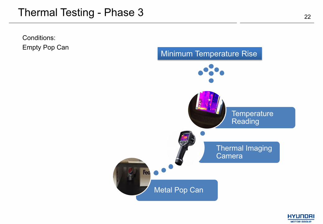
Conditions:Empty Pop Can
22
Metal Pop Can
Thermal Imaging Camera
Temperature Reading
Minimum Temperature Rise

23Conclusion
Observations: Adhesive materials used in housing assembly have effect on resonant circuit characteristics.
Unique considerations of closed-loop control system; have to consider WiFi delay and effect of output
voltage on system response.
Good thermal results; minimal temperature rise.
AM radio interference during power transfer.
Electromagnetic interference can disrupt test equipment, even user laptop
What Else Do We Want to Learn? What are the effects to other wireless communication systems in the vehicle (TPMS, cellular, WiFi, etc.)
What are the effects on the powertrain components? Important to know if considering dynamic
charging.
Attribute Project Goal AchievedPower Transferred >6.6 kW 10 kWGrid to EV Efficiency >85% 92%Coil-To-Coil Gap 20cm 20cmEMI Below ICNIRP 1% - 10% of ICNIRP

24
Complete fleet build-up Three systems remaining
Continue to support INL testing System was delivered, testing and analysis in progress
System testing at Hyundai Technical Center System performance Electrical endurance Vehicle durability Emissions
Next Steps
25Collaborations and Coordination with Other Institutions
Mojo Mobility Sub-recipient of award no. DE-EE0005963. Responsible for design, development of wireless charging system. Currently developing wireless charging systems for consumer electronics,
and automotive applications.
Society of Automotive Engineers (SAE) J2954 Wireless Charging Task Force (Voting Member) J2836/6 Wireless Charging Specific Use Cases (Voting Member) J2847/6 Wireless Charging Specific Messages (Voting Member) J2931/6 Wireless Charging Specific Protocols (Voting Member)

End 26