
HIGH EFFICIENCY INDUSTRIAL AIRFOIL FANS F n
20
CATALOG 1150 | MAY 2011 WWW.TCF.COM INDUSTRIAL PROCESS AND COMMERCIAL VENTILATION SYSTEMS Twin City Fan HIGH EFFICIENCY INDUSTRIAL AIRFOIL FANS MODEL HAF
Transcript of HIGH EFFICIENCY INDUSTRIAL AIRFOIL FANS F n
CATALOG 1150 | MAY 2011 WWW.TCF.COM
INDUSTRIAL PROCESS AND
COMMERCIAL VENTILATION SYSTEMS
Twin City Fan
Twin City FanHIGH EFFICIENCYINDUSTRIAL AIRFOIL FANSMODEL HAF

Twin City Catalog 11502
HAF High Efficiency Industrial Airfoil FansModel HAF fans from Twin City Fan & Blower employ a high efficiency non-overloading airfoil wheel in a ruggedly constructed fan housing. These fans are designed to handle clean air.
Standard Features• Heavy-gauge, all welded, high efficiency, non-
overloading airfoil wheels are provided on all sizes and arrangements.
• Statically and dynamically balanced rotor assembly.
• Heavy duty self-aligning grease lubricated anti-friction pillow block bearings. See page 7 for sizes and types.
• Shaft turned ground, polished, and straightened to close tolerances.
• Heavy-gauge reinforced housing and bearing pedestal for vibration-free service.
• All arrangements include our standard shaft seal.
• Flanged inlet and outlet.• Lifting lugs.
HAF High EfficiencyAirfoil Wheel
Arrangement 4 on Isolation Base
Typical Applications• Product cooling• Fluidizing systems• Solvent recovery systems• Moisture blow-off• Forced draft • Dryer applications• Recirculation systems
Capabilities• Air flow up to 160,000 CFM• Wheel diameters from 25" to 82"• High temperature construction to 600°F available
Class 30• Suitable to 23,000 FPM tip speed• Pressure to 30" w.g.
Class 40• Suitable to 27,800 FPM tip speed• Pressure to 40" w.g.
Class 50• Suitable to 29,700 FPM tip speed• Pressure to 50" w.g.
Twin City Fan
Twin City Fan
Twin City Catalog 1150 3
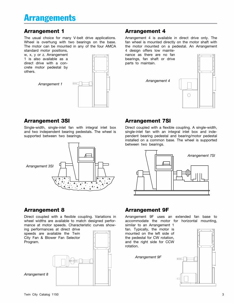
ArrangementsArrangement 1The usual choice for many V-belt drive applications. Wheel is overhung with two bearings on the base. The motor can be mounted in any of the four AMCA standard motor positions, w, x, y or z. Arrangement 1 is also available as a direct drive with a con-crete motor pedestal by others.
Arrangement 8
Arrangement 4Arrangement 1
Arrangement 4Arrangement 4 is available in direct drive only. The fan wheel is mounted directly on the motor shaft with the motor mounted on a pedestal. An Arrangement 4 design offers low mainte-nance as there are no fan bearings, fan shaft or drive parts to maintain.
Arrangement 9FArrangement 9F uses an extended fan base to accommodate the motor for horizontal mounting, similar to an Arrangement 1 fan. Typically, the motor is mounted on the left side of the pedestal for CW rotation, and the right side for CCW rotation.
Arrangement 9F
Arrangement 8Direct coupled with a flexible coupling. Variations in wheel widths are available to match designed perfor-mance at motor speeds. Characteristic curves show-ing performances at direct drive speeds are available the Twin City Fan & Blower Fan Selector Program.
Arrangement 3SI
Arrangement 7SIDirect coupled with a flexible coupling. A single-width, single-inlet fan with an integral inlet box and inde-pendent bearing pedestal and bearing/motor pedestal installed on a common base. The wheel is supported between two bearings.
Arrangement 3SISingle-width, single-inlet fan with integral inlet box and two independent bearing pedestals. The wheel is supported between two bearings.
Arrangement 7SI
Twin City Catalog 11504
Inlet BoxesIntegral or detached type generously designed to minimize pressure drop.
INLET BOX POSITIONS AND DESCRIPTIONS
45 — Angular Down Intake 90 — Horizontal Right Intake 135 — Angular Up Intake 180 — Bottom Up Intake 225 — Angular Up Intake 270 — Horizontal Left Intake 315 — Angular Down Intake 360 — Top Down Intake
Inlet Box Positions For Centrifugal Fans
Reference line is the Top Vertical Axis through center of fan shaft.
Position of inlet box and air entry to inlet box is determined from drive side of fan.
Position of inlet box is designated in degrees clockwise from Top Vertical Axis as shown.
Positions 135° to 225° in some cases interfere seriously with floor structure.
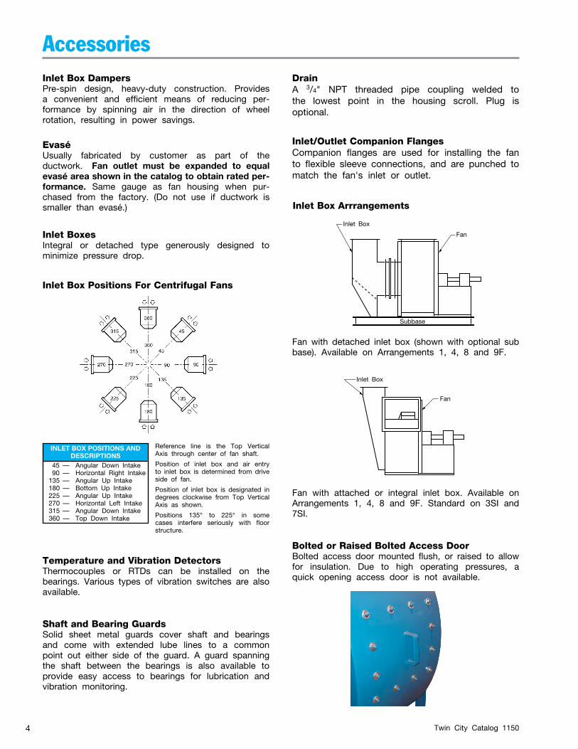
Inlet Box Arrrangements
Bolted or Raised Bolted Access DoorBolted access door mounted flush, or raised to allow for insulation. Due to high operating pressures, a quick opening access door is not available.
AccessoriesInlet Box DampersPre-spin design, heavy-duty construction. Provides a convenient and efficient means of reducing per-formance by spinning air in the direction of wheel rotation, resulting in power savings.
Inlet Box
Fan
Subbase
Fan with detached inlet box (shown with optional sub base). Available on Arrangements 1, 4, 8 and 9F.
Inlet Box
Fan
Fan with attached or integral inlet box. Available on Arrangements 1, 4, 8 and 9F. Standard on 3SI and 7SI.
Temperature and Vibration DetectorsThermocouples or RTDs can be installed on the bearings. Various types of vibration switches are also available.
Shaft and Bearing GuardsSolid sheet metal guards cover shaft and bearings and come with extended lube lines to a common point out either side of the guard. A guard spanning the shaft between the bearings is also available to provide easy access to bearings for lubrication and vibration monitoring.
Inlet/Outlet Companion FlangesCompanion flanges are used for installing the fan to flexible sleeve connections, and are punched to match the fan's inlet or outlet.
EvaséUsually fabricated by customer as part of the ductwork. Fan outlet must be expanded to equal evasé area shown in the catalog to obtain rated per-formance. Same gauge as fan housing when pur-chased from the factory. (Do not use if ductwork is smaller than evasé.)
Drain A 3/4" NPT threaded pipe coupling welded to the lowest point in the housing scroll. Plug is optional.
Twin City Catalog 1150 5
Accessories
External Variable Inlet VanesWorks on the same principle as inlet box dampers. Only external bolt on type variable inlet vanes are available.
Optional ConstructionHigh Temperature ModificationsAir stream temperatures of 301-500°F are modified to use high temperature grease, expansion and non-expansion bearings and shaft cooler. TCF&B standard paint is suitable up to 500°F. Air stream temperatures of 501-600°F use the same construction as above with the addition of high temperature paint. Consult factory for applications above 600°F. Arrangement 4 fans are not suitable for applications above 150°F.
Spark Resistant ConstructionType 'C' spark resistant is available per AMCA standard 99-0401-86. Twin City Fan offers type 'C' suitable to 600°F. Consult factory where nonferrous metal other than aluminum is specified. Type 'B' is NOT available.
Split HousingsSize 220-330 fans are designed to permit wheel re-moval through the fan inlet. Sizes 360 and larger are standard with a pie-shaped split housing, which allows removal of the wheel and shaft without disconnecting the inner and outlet ductwork. A pie-split housing is required with fans utilizing an integral inlet box.
Unitary BaseA structural steel base provides common support to fan, motor, and drive including guards. This style of base is designed for use without isolators and requires adequate foundation integrity (provided and designed by others) for proper installation, and vibra-tion free fan operation.
Vibration Isolation BasesHeavy structural base for fan, motor and drive is de-signed for use with spring or rubber- in-shear type isolators. Use of flexible connectors at inlet and outlet is required on fans with isolators.
Oil Circulation UnitForce feed lubrication units can be supplied for applications that require oil circulation for bearings.
Outlet DampersThe closing of the damper adds to the resistance that the fan is working against. This moves the operating point to the left of the initial rating point. The savings in horsepower depends on the relative position on the fan curve and is usually much less than offered by other methods. Outlet dampers are typically the least expensive option and should be considered when infrequent operation at lesser capacity is desired or when handling hot, humid or particulate laden air. There are two types of outlet dampers: parallel blade and opposed blade. Parallel blade dampers are recommended for systems where air volume is modulated between full-open to about 75% of open. Opposed blade dampers cost about 10% more and are recommended for systems where volume is modulated over the entire range. Opposed blades reduce air volume in a closer relationship to the con-trol arm movement.
Belt GuardsA belt guard protects personnel from the moving drive parts. Both standard and totally enclosed type guards are available.
Twin City Catalog 11506
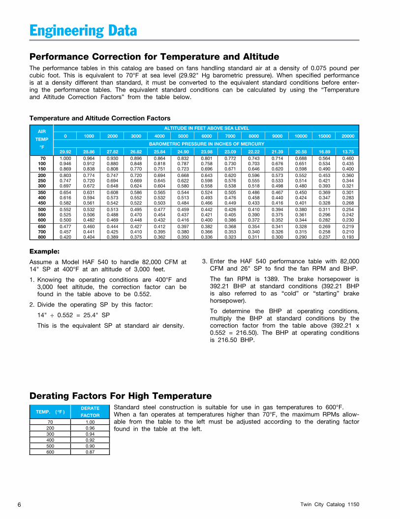
Standard steel construction is suitable for use in gas temperatures to 600°F.When a fan operates at temperatures higher than 70°F, the maximum RPMs allow-able from the table to the left must be adjusted according to the derating factor found in the table at the left.
Derating Factors For High Temperature
Temperature and Altitude Correction Factors
AIR ALTITUDE IN FEET ABOVE SEA LEVEL
TEMP
0 1000 2000 3000 4000 5000 6000 7000 8000 9000 10000 15000 20000
°F
BAROMETRIC PRESSURE IN INCHES OF MERCURY
29.92 28.86 27.82 26.82 25.84 24.90 23.98 23.09 22.22 21.39 20.58 16.89 13.75 70 1.000 0.964 0.930 0.896 0.864 0.832 0.801 0.772 0.743 0.714 0.688 0.564 0.460 100 0.946 0.912 0.880 0.848 0.818 0.787 0.758 0.730 0.703 0.676 0.651 0.534 0.435 150 0.869 0.838 0.808 0.770 0.751 0.723 0.696 0.671 0.646 0.620 0.598 0.490 0.400 200 0.803 0.774 0.747 0.720 0.694 0.668 0.643 0.620 0.596 0.573 0.552 0.453 0.360 250 0.747 0.720 0.694 0.669 0.645 0.622 0.598 0.576 0.555 0.533 0.514 0.421 0.344 300 0.697 0.672 0.648 0.624 0.604 0.580 0.558 0.538 0.518 0.498 0.480 0.393 0.321 350 0.654 0.631 0.608 0.586 0.565 0.544 0.524 0.505 0.486 0.467 0.450 0.369 0.301 400 0.616 0.594 0.573 0.552 0.532 0.513 0.493 0.476 0.458 0.440 0.424 0.347 0.283 450 0.582 0.561 0.542 0.522 0.503 0.484 0.466 0.449 0.433 0.416 0.401 0.328 0.268 500 0.552 0.532 0.513 0.495 0.477 0.459 0.442 0.426 0.410 0.394 0.380 0.311 0.254 550 0.525 0.506 0.488 0.470 0.454 0.437 0.421 0.405 0.390 0.375 0.361 0.296 0.242 600 0.500 0.482 0.469 0.448 0.432 0.416 0.400 0.386 0.372 0.352 0.344 0.282 0.230 650 0.477 0.460 0.444 0.427 0.412 0.397 0.382 0.368 0.354 0.341 0.328 0.269 0.219 700 0.457 0.441 0.425 0.410 0.395 0.380 0.366 0.353 0.340 0.326 0.315 0.258 0.210 800 0.420 0.404 0.389 0.375 0.362 0.350 0.336 0.323 0.311 0.300 0.290 0.237 0.193
Engineering Data
Performance Correction for Temperature and AltitudeThe performance tables in this catalog are based on fans handling standard air at a density of 0.075 pound per cubic foot. This is equivalent to 70°F at sea level (29.92" Hg barometric pressure). When specified performance is at a density different than standard, it must be converted to the equivalent standard conditions before enter-ing the performance tables. The equivalent standard conditions can be calculated by using the “Temperature and Altitude Correction Factors” from the table below.
Example:
Assume a Model HAF 540 to handle 82,000 CFM at 14" SP at 400°F at an altitude of 3,000 feet.
1. Knowing the operating conditions are 400°F and 3,000 feet altitude, the correction factor can be found in the table above to be 0.552.
2. Divide the operating SP by this factor:
14" ÷ 0.552 = 25.4" SP
This is the equivalent SP at standard air density.
3. Enter the HAF 540 performance table with 82,000 CFM and 26" SP to find the fan RPM and BHP.
The fan RPM is 1389. The brake horsepower is 392.21 BHP at standard conditions (392.21 BHP is also referred to as “cold” or “starting” brake horsepower).
To determine the BHP at operating conditions, multiply the BHP at standard conditions by the correction factor from the table above (392.21 x 0.552 = 216.50). The BHP at operating conditions is 216.50 BHP.
TEMP. ( oF )DERATE
FACTOR70 1.00200 0.96300 0.94400 0.92500 0.90600 0.87
Twin City Catalog 1150 7
Engineering Data
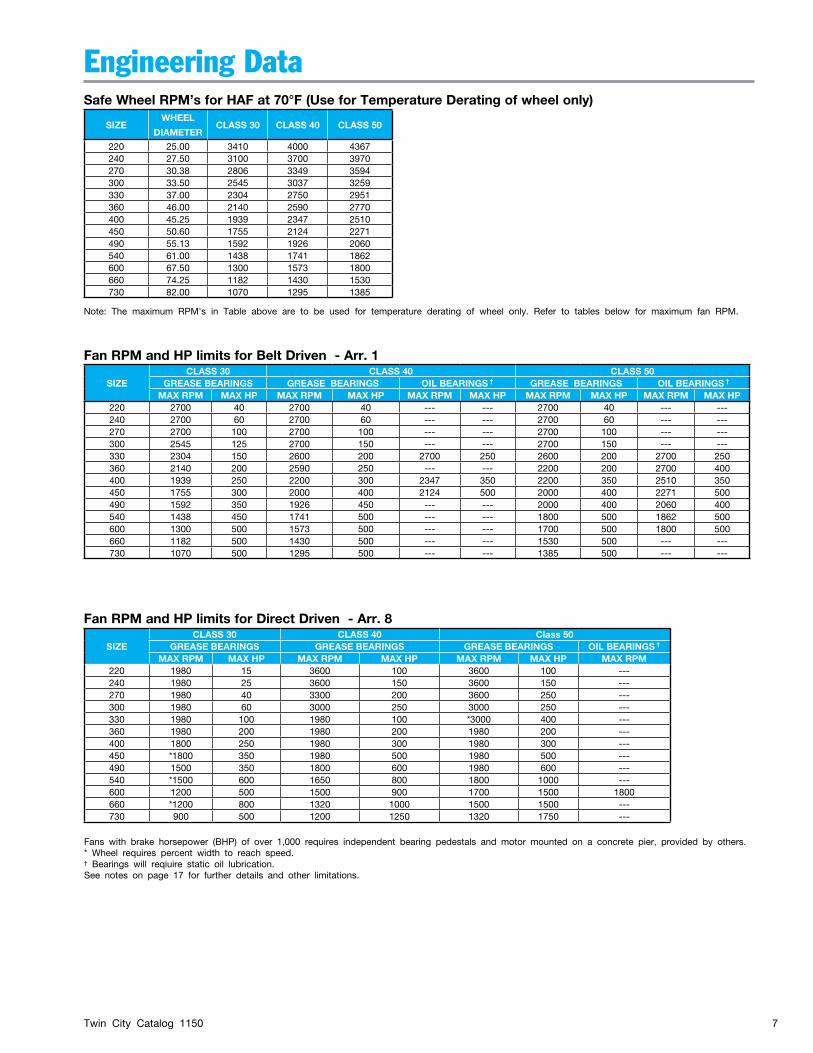
SIZEWHEEL
DIAMETERCLASS 30 CLASS 40 CLASS 50
220 25.00 3410 4000 4367240 27.50 3100 3700 3970270 30.38 2806 3349 3594300 33.50 2545 3037 3259330 37.00 2304 2750 2951360 46.00 2140 2590 2770400 45.25 1939 2347 2510450 50.60 1755 2124 2271490 55.13 1592 1926 2060540 61.00 1438 1741 1862600 67.50 1300 1573 1800660 74.25 1182 1430 1530730 82.00 1070 1295 1385
SIZECLASS 30 CLASS 40 CLASS 50
GREASE BEARINGS GREASE BEARINGS OIL BEARINGS † GREASE BEARINGS OIL BEARINGS †
MAX RPM MAX HP MAX RPM MAX HP MAX RPM MAX HP MAX RPM MAX HP MAX RPM MAX HP220 2700 40 2700 40 --- --- 2700 40 --- ---240 2700 60 2700 60 --- --- 2700 60 --- ---270 2700 100 2700 100 --- --- 2700 100 --- ---300 2545 125 2700 150 --- --- 2700 150 --- ---330 2304 150 2600 200 2700 250 2600 200 2700 250360 2140 200 2590 250 --- --- 2200 200 2700 400400 1939 250 2200 300 2347 350 2200 350 2510 350450 1755 300 2000 400 2124 500 2000 400 2271 500490 1592 350 1926 450 --- --- 2000 400 2060 400540 1438 450 1741 500 --- --- 1800 500 1862 500600 1300 500 1573 500 --- --- 1700 500 1800 500660 1182 500 1430 500 --- --- 1530 500 --- ---730 1070 500 1295 500 --- --- 1385 500 --- ---
SIZECLASS 30 CLASS 40 Class 50
GREASE BEARINGS GREASE BEARINGS GREASE BEARINGS OIL BEARINGS †
MAX RPM MAX HP MAX RPM MAX HP MAX RPM MAX HP MAX RPM220 1980 15 3600 100 3600 100 ---240 1980 25 3600 150 3600 150 ---270 1980 40 3300 200 3600 250 ---300 1980 60 3000 250 3000 250 ---330 1980 100 1980 100 *3000 400 ---360 1980 200 1980 200 1980 200 ---400 1800 250 1980 300 1980 300 ---450 *1800 350 1980 500 1980 500 ---490 1500 350 1800 600 1980 600 ---540 *1500 600 1650 800 1800 1000 ---600 1200 500 1500 900 1700 1500 1800660 *1200 800 1320 1000 1500 1500 ---730 900 500 1200 1250 1320 1750 ---
Safe Wheel RPM’s for HAF at 70°F (Use for Temperature Derating of wheel only)
Fan RPM and HP limits for Belt Driven - Arr. 1
Fan RPM and HP limits for Direct Driven - Arr. 8
Note: The maximum RPM's in Table above are to be used for temperature derating of wheel only. Refer to tables below for maximum fan RPM.
Fans with brake horsepower (BHP) of over 1,000 requires independent bearing pedestals and motor mounted on a concrete pier, provided by others.* Wheel requires percent width to reach speed.† Bearings will reqiuire static oil lubrication. See notes on page 17 for further details and other limitations.
Twin City Catalog 11508
Engineering Data
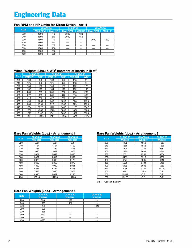
SIZECLASS 30 CLASS 40 CLASS 50
MAX RPM MAX HP MAX RPM MAX HP MAX RPM MAX HP220 1800 10 3600 100 --- ---240 1800 20 3600 150 --- ---270 1800 30 --- --- 3600 200300 1800 50 --- ---330 1800 75 --- --- --- ---360 1800 150 --- --- --- ---400 1800 200 --- --- --- ---450 1800 300 --- --- --- ---
SIZECLASS 30 CLASS 40 CLASS 50
WEIGHT WR2 WEIGHT WR2 WEIGHT WR2
220 109 56 109 56 115 61240 125 80 125 80 133 87270 154 120 159 123 162 128300 182 179 184 178 192 190330 235 268 235 267 156 286360 272 396 301 447 315 469400 416 707 427 726 451 799450 495 1069 508 1096 526 1159490 689 1791 728 1946 729 1930540 1084 3322 1122 3462 1129 3547600 1252 4936 1275 5053 1304 5663660 1627 8147 1641 8037 1582 8325730 1911 11979 1871 11918 1879 12154
Fan RPM and HP Limits for Direct Driven - Arr. 4
Wheel Weights (Lbs.) & WR2 (moment of inertia in lb-ft2)
SIZECLASS 30 CLASS 40 CLASS 50WEIGHT WEIGHT WEIGHT
220 972 972 978240 1154 1154 1162270 1357 1362 1405300 1610 1667 1675330 2001 2049 2060360 2437 2512 2562400 3022 3098 3123450 3680 3853 3872490 4889 4999 5001540 6267 6354 6443600 7535 7650 7975660 8940 9061 9250730 10818 11259 11268
SIZECLASS 30 CLASS 40 CLASS 50WEIGHT WEIGHT WEIGHT
220 820 1199 ---240 1025 1456 ---270 1290 --- 1912300 1585 --- ---330 1838 --- ---360 2720 --- ---400 3441 --- ---450 4095 --- ---
SIZECLASS 30 CLASS 40 CLASS 50WEIGHT WEIGHT WEIGHT
220 1132 1550 1557240 1358 1858 1866270 1598 2244 2287300 1985 2602 2610330 2531 2558 3504360 3459 3513 3538400 4277 4285 4310450 5008 5434 5453490 6182 6602 6552540 8036 9347 10100600 9372 11214 C.F.660 12397 C.F. C.F.730 13225 C.F. C.F.
Bare Fan Weights (Lbs.) - Arrangement 4
Bare Fan Weights (Lbs.) - Arrangement 1 Bare Fan Weights (Lbs.) - Arrangement 8
C.F. - Consult Factory
Twin City Catalog 1150 9
Engineering Data
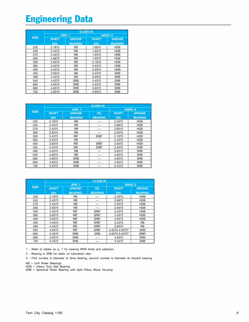
SIZE
CLASS 40ARR. 1 ARRG. 8
SHAFT
DIA.
GREASE
BEARING
OIL
BEARING
SHAFT
DIA.
GREASE
BEARING 220 2.1875 RB --- 2.4375 HDB240 2.4375 RB --- 2.6875 HDB270 2.4375 RB --- 2.9375 HDB300 2.9375 RB --- 2.9375 HDB330 3.4375 RB1 SRB1 2.1875 HDB360 3.4375 RB --- 2.4375 HDB400 3.9375 RB1 SRB1 2.9375 HDB450 4.4375 RB1 SRB1 3.4375 SRB490 4.4375 RB --- 3.9375 SRB540 4.9375 RB --- 4.9375 SRB600 4.9375 SRB --- 4.9375 SRB660 4.9375 SRB --- 4.9375 SRB730 5.4375 SRB --- 5.4375 SRB
SIZE
CLASS 50ARR. 1 ARRG. 8
SHAFT
DIA.
GREASE
BEARING
OIL
BEARING
SHAFT
DIA.
GREASE
BEARING 220 2.1875 RB --- 2.4375 HDB240 2.4375 RB --- 2.6875 HDB270 2.4375 RB --- 2.9375 HDB300 2.9375 RB --- 2.9375 HDB330 3.4375 RB1 SRB1 3.4375 HDB360 3.9375 RB1 SRB1 2.4375 HDB400 3.9375 RB1 SRB1 2.9375 HDB450 4.4375 RB1 SRB1 3.4375 RB490 4.4375 RB1 SRB1 3.9375 RB540 4.9375 RB1 SRB1 4.4375-4.93753 SRB600 5.4375 SRB SRB 4.9375-5.43753 SRB2
660 4.9375 SRB --- 4.9375 SRB730 5.4375 SRB --- 5.4375 SRB
1 - Refer to tables on p. 7 for bearing RPM limits and selection.
2 - Bearing is SRB for static oil lubrication also
3 - First number is diameter at drive bearing, second number is diameter at inboard bearing.
SIZE
CLASS 30ARR. 1 ARRG. 8
SHAFT
DIA.
GREASE
BEARING
SHAFT
DIA.
GREASE
BEARING 220 2.1875 RB 1.6875 HDB240 2.4375 RB 1.9375 HDB270 2.4375 RB 1.9375 HDB300 2.6875 RB 1.9375 HDB330 2.9375 RB 2.1875 HDB360 3.4375 RB 2.4375 HDB400 3.4375 RB 2.9375 HDB450 3.9375 RB 3.4375 SRB490 4.4375 RB 3.9375 SRB540 4.4375 SRB 4.4375 SRB600 4.9375 SRB 4.4375 SRB660 4.9375 SRB 4.9375 SRB730 4.9375 SRB 4.9375 SRB
RB = Unit Roller Bearings HDB = Heavy Duty Ball BearingSRB = Spherical Roller Bearing with Split Pillow Block Housing
Twin City Catalog 115010
Performance Data
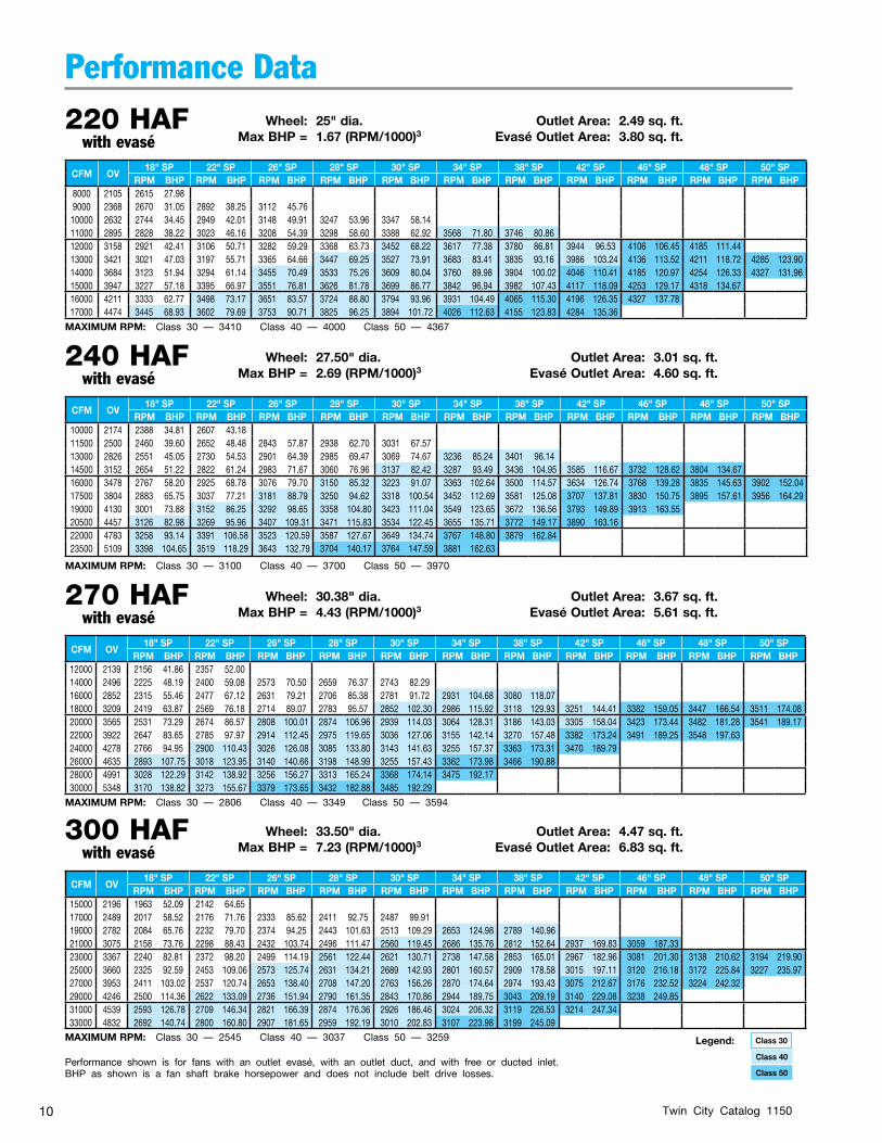
240 HAF Wheel: 27.50" dia. Outlet Area: 3.01 sq. ft. with evasé Max BHP = 2.69 (RPM/1000)3 Evasé Outlet Area: 4.60 sq. ft.
220 HAF Wheel: 25" dia. Outlet Area: 2.49 sq. ft. with evasé Max BHP = 1.67 (RPM/1000)3 Evasé Outlet Area: 3.80 sq. ft.
270 HAF Wheel: 30.38" dia. Outlet Area: 3.67 sq. ft. with evasé Max BHP = 4.43 (RPM/1000)3 Evasé Outlet Area: 5.61 sq. ft.
Performance shown is for fans with an outlet evasé, with an outlet duct, and with free or ducted inlet.BHP as shown is a fan shaft brake horsepower and does not include belt drive losses.
CFM OV18" SP 22" SP 26" SP 28" SP 30" SP 34" SP 38" SP 42" SP 46" SP 48" SP 50" SP
RPM BHP RPM BHP RPM BHP RPM BHP RPM BHP RPM BHP RPM BHP RPM BHP RPM BHP RPM BHP RPM BHP8000 2105 2615 27.989000 2368 2670 31.05 2892 38.25 3112 45.7610000 2632 2744 34.45 2949 42.01 3148 49.91 3247 53.96 3347 58.1411000 2895 2828 38.22 3023 46.16 3208 54.39 3298 58.60 3388 62.92 3568 71.80 3746 80.8612000 3158 2921 42.41 3106 50.71 3282 59.29 3368 63.73 3452 68.22 3617 77.38 3780 86.81 3944 96.53 4106 106.45 4185 111.4413000 3421 3021 47.03 3197 55.71 3365 64.66 3447 69.25 3527 73.91 3683 83.41 3835 93.16 3986 103.24 4136 113.52 4211 118.72 4285 123.9014000 3684 3123 51.94 3294 61.14 3455 70.49 3533 75.26 3609 80.04 3760 89.98 3904 100.02 4046 110.41 4185 120.97 4254 126.33 4327 131.9615000 3947 3227 57.18 3395 66.97 3551 76.81 3626 81.78 3699 86.77 3842 96.94 3982 107.43 4117 118.09 4253 129.17 4318 134.6716000 4211 3333 62.77 3498 73.17 3651 83.57 3724 88.80 3794 93.96 3931 104.49 4065 115.30 4196 126.35 4327 137.7817000 4474 3445 68.93 3602 79.69 3753 90.71 3825 96.25 3894 101.72 4026 112.63 4155 123.83 4284 135.36
CFM OV18" SP 22" SP 26" SP 28" SP 30" SP 34" SP 38" SP 42" SP 46" SP 48" SP 50" SP
RPM BHP RPM BHP RPM BHP RPM BHP RPM BHP RPM BHP RPM BHP RPM BHP RPM BHP RPM BHP RPM BHP10000 2174 2388 34.81 2607 43.1811500 2500 2460 39.60 2652 48.48 2843 57.87 2938 62.70 3031 67.5713000 2826 2551 45.05 2730 54.53 2901 64.39 2985 69.47 3069 74.67 3236 85.24 3401 96.1414500 3152 2654 51.22 2822 61.24 2983 71.67 3060 76.96 3137 82.42 3287 93.49 3436 104.95 3585 116.67 3732 128.62 3804 134.6716000 3478 2767 58.20 2925 68.78 3076 79.70 3150 85.32 3223 91.07 3363 102.64 3500 114.57 3634 126.74 3768 139.28 3835 145.63 3902 152.0417500 3804 2883 65.75 3037 77.21 3181 88.79 3250 94.62 3318 100.54 3452 112.69 3581 125.08 3707 137.81 3830 150.75 3895 157.61 3956 164.2919000 4130 3001 73.88 3152 86.25 3292 98.65 3358 104.80 3423 111.04 3549 123.65 3672 136.56 3793 149.89 3913 163.5520500 4457 3126 82.98 3269 95.96 3407 109.31 3471 115.83 3534 122.45 3655 135.71 3772 149.17 3890 163.1622000 4783 3258 93.14 3391 106.58 3523 120.59 3587 127.67 3649 134.74 3767 148.80 3879 162.8423500 5109 3398 104.65 3519 118.29 3643 132.79 3704 140.17 3764 147.59 3881 162.63
CFM OV18" SP 22" SP 26" SP 28" SP 30" SP 34" SP 38" SP 42" SP 46" SP 48" SP 50" SP
RPM BHP RPM BHP RPM BHP RPM BHP RPM BHP RPM BHP RPM BHP RPM BHP RPM BHP RPM BHP RPM BHP12000 2139 2156 41.86 2357 52.0014000 2496 2225 48.19 2400 59.08 2573 70.50 2659 76.37 2743 82.2916000 2852 2315 55.46 2477 67.12 2631 79.21 2706 85.38 2781 91.72 2931 104.68 3080 118.0718000 3209 2419 63.87 2569 76.18 2714 89.07 2783 95.57 2852 102.30 2986 115.92 3118 129.93 3251 144.41 3382 159.05 3447 166.54 3511 174.0820000 3565 2531 73.29 2674 86.57 2808 100.01 2874 106.96 2939 114.03 3064 128.31 3186 143.03 3305 158.04 3423 173.44 3482 181.28 3541 189.1722000 3922 2647 83.65 2785 97.97 2914 112.45 2975 119.65 3036 127.06 3155 142.14 3270 157.48 3382 173.24 3491 189.25 3548 197.6324000 4278 2766 94.95 2900 110.43 3026 126.08 3085 133.80 3143 141.63 3255 157.37 3363 173.31 3470 189.7926000 4635 2893 107.75 3018 123.95 3140 140.66 3198 148.99 3255 157.43 3362 173.98 3466 190.8828000 4991 3028 122.29 3142 138.92 3256 156.27 3313 165.24 3368 174.14 3475 192.1730000 5348 3170 138.82 3273 155.67 3379 173.65 3432 182.88 3485 192.29
300 HAF Wheel: 33.50" dia. Outlet Area: 4.47 sq. ft. with evasé Max BHP = 7.23 (RPM/1000)3 Evasé Outlet Area: 6.83 sq. ft.
CFM OV18" SP 22" SP 26" SP 28" SP 30" SP 34" SP 38" SP 42" SP 46" SP 48" SP 50" SP
RPM BHP RPM BHP RPM BHP RPM BHP RPM BHP RPM BHP RPM BHP RPM BHP RPM BHP RPM BHP RPM BHP15000 2196 1963 52.09 2142 64.6517000 2489 2017 58.52 2176 71.76 2333 85.62 2411 92.75 2487 99.9119000 2782 2084 65.76 2232 79.70 2374 94.25 2443 101.63 2513 109.29 2653 124.98 2789 140.9621000 3075 2158 73.76 2298 88.43 2432 103.74 2496 111.47 2560 119.45 2686 135.76 2812 152.64 2937 169.83 3059 187.3323000 3367 2240 82.81 2372 98.20 2499 114.19 2561 122.44 2621 130.71 2738 147.58 2853 165.01 2967 182.96 3081 201.30 3138 210.62 3194 219.9025000 3660 2325 92.59 2453 109.06 2573 125.74 2631 134.21 2689 142.93 2801 160.57 2909 178.58 3015 197.11 3120 216.18 3172 225.84 3227 235.9727000 3953 2411 103.02 2537 120.74 2653 138.40 2708 147.20 2763 156.26 2870 174.64 2974 193.43 3075 212.67 3176 232.52 3224 242.3229000 4246 2500 114.36 2622 133.09 2736 151.94 2790 161.35 2843 170.86 2944 189.75 3043 209.19 3140 229.08 3238 249.8531000 4539 2593 126.78 2709 146.34 2821 166.39 2874 176.36 2926 186.46 3024 206.32 3119 226.53 3214 247.3433000 4832 2692 140.74 2800 160.80 2907 181.65 2959 192.19 3010 202.83 3107 223.98 3199 245.09
Class 30Legend:
Class 50
Class 40
MAXIMUM RPM: Class 30 — 3410 Class 40 — 4000 Class 50 — 4367
MAXIMUM RPM: Class 30 — 3100 Class 40 — 3700 Class 50 — 3970
MAXIMUM RPM: Class 30 — 2806 Class 40 — 3349 Class 50 — 3594
MAXIMUM RPM: Class 30 — 2545 Class 40 — 3037 Class 50 — 3259
Twin City Catalog 1150 11
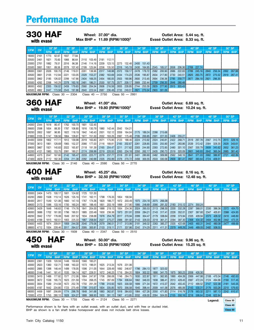
Performance Data330 HAF Wheel: 37.00" dia. Outlet Area: 5.44 sq. ft. with evasé Max BHP = 11.89 (RPM/1000)3 Evasé Outlet Area: 8.33 sq. ft.
360 HAF Wheel: 41.00" dia. Outlet Area: 6.69 sq. ft. with evasé Max BHP = 19.80 (RPM/1000)3 Evasé Outlet Area: 10.24 sq. ft.
CFM OV18" SP 22" SP 26" SP 28" SP 30" SP 34" SP 38" SP 42" SP 46" SP 48" SP 50" SP
RPM BHP RPM BHP RPM BHP RPM BHP RPM BHP RPM BHP RPM BHP RPM BHP RPM BHP RPM BHP RPM BHP18000 2161 1773 62.67 1937 77.8420500 2461 1821 70.60 1966 86.64 2110 103.49 2181 112.1123000 2761 1882 79.51 2016 96.38 2146 114.16 2209 123.15 2273 132.48 2400 151.4325500 3061 1951 89.56 2078 107.40 2199 125.94 2258 135.50 2316 145.19 2430 164.95 2545 185.57 2658 206.36 2769 227.7428000 3361 2026 100.70 2146 119.51 2261 138.96 2317 148.98 2372 159.17 2478 179.72 2582 200.90 2686 222.93 2789 245.16 2840 256.34 2892 267.9830500 3661 2105 112.94 2221 133.05 2329 153.27 2382 163.69 2434 174.23 2536 195.87 2634 217.90 2730 240.51 2825 263.75 2872 275.52 2919 287.4133000 3962 2185 126.02 2299 147.66 2404 169.25 2454 180.05 2503 190.96 2600 213.45 2694 236.38 2785 259.77 2877 284.19 2921 296.3535500 4262 2268 140.29 2378 163.16 2481 186.21 2530 197.75 2577 209.17 2669 232.44 2759 256.35 2846 280.4838000 4562 2355 156.02 2459 179.83 2560 204.34 2608 216.58 2655 228.95 2744 253.39 2829 277.90 2915 303.4340500 4862 2447 173.58 2543 197.88 2640 223.54 2687 236.48 2733 249.51 2821 275.54 2903 301.09
CFM OV18" SP 22" SP 26" SP 28" SP 30" SP 34" SP 38" SP 42" SP 46" SP 48" SP 50" SP
RPM BHP RPM BHP RPM BHP RPM BHP RPM BHP RPM BHP RPM BHP RPM BHP RPM BHP RPM BHP RPM BHP24000 2344 1618 80.47 1762 100.70 1901 122.4526600 2598 1654 88.30 1787 108.80 1916 130.79 1980 142.44 2042 154.2129200 2852 1697 96.95 1822 118.19 1942 140.43 2001 152.12 2059 164.04 2175 189.24 2288 215.6831800 3105 1747 106.56 1864 128.61 1977 151.50 2032 163.26 2087 175.48 2195 200.85 2301 227.33 2406 255.2734400 3359 1802 117.11 1912 139.98 2019 163.83 2071 175.95 2123 188.46 2224 213.92 2324 240.81 2422 268.71 2519 297.78 2567 312.75 2615 328.1637000 3613 1861 128.69 1965 152.37 2066 177.03 2116 189.81 2165 202.67 2261 228.85 2355 255.90 2447 283.86 2539 313.42 2584 328.35 2629 343.6139600 3867 1921 140.83 2022 165.87 2118 191.39 2165 204.47 2211 217.62 2303 244.90 2393 272.85 2480 301.10 2567 330.79 2609 345.62 2652 361.2342200 4121 1983 153.75 2081 180.21 2174 206.99 2219 220.55 2263 234.18 2350 262.17 2435 290.73 2519 320.09 2601 349.93 2642 365.34 2685 381.4044800 4375 2047 167.60 2142 195.47 2233 223.77 2276 237.77 2318 251.81 2401 280.60 2482 309.99 2562 340.16 2641 371.03 2682 386.97 2721 402.8947400 4629 2112 182.30 2204 211.38 2292 240.99 2335 255.99 2376 270.72 2456 300.55 2533 330.58 2609 361.41 2687 393.64 2724 409.51
400 HAF Wheel: 45.25" dia. Outlet Area: 8.16 sq. ft. with evasé Max BHP = 32.50 (RPM/1000)3 Evasé Outlet Area: 12.48 sq. ft.
CFM OV18" SP 22" SP 26" SP 28" SP 30" SP 34" SP 38" SP 42" SP 46" SP 48" SP 50" SP
RPM BHP RPM BHP RPM BHP RPM BHP RPM BHP RPM BHP RPM BHP RPM BHP RPM BHP RPM BHP RPM BHP30000 2404 1473 100.17 1601 124.92 1725 151.5033200 2660 1508 110.14 1626 135.16 1741 162.11 1798 176.35 1854 190.9436400 2917 1549 121.06 1660 147.10 1767 174.36 1820 188.77 1872 203.49 1975 234.18 2075 266.0839600 3173 1596 133.16 1700 160.24 1801 188.45 1851 203.19 1899 217.80 1995 248.69 2090 281.32 2183 315.12 2274 350.2442800 3429 1648 146.63 1746 174.76 1841 204.00 1888 219.13 1934 234.36 2024 265.53 2113 298.30 2200 332.28 2287 368.01 2330 386.36 2372 404.7046000 3686 1702 161.00 1796 190.51 1885 220.49 1930 236.36 1973 251.91 2059 284.21 2143 317.41 2226 352.01 2307 387.60 2347 405.81 2388 424.9349200 3942 1757 176.08 1849 207.52 1934 238.68 1976 254.79 2017 270.94 2099 304.47 2179 338.64 2258 373.94 2335 409.94 2373 428.32 2410 446.6052400 4199 1815 192.51 1903 225.33 1987 258.64 2027 275.27 2066 291.92 2143 326.03 2219 361.21 2294 397.30 2368 434.32 2404 452.86 2442 472.2555600 4455 1874 209.91 1959 244.30 2040 279.06 2079 296.51 2117 313.99 2191 349.32 2263 385.27 2335 422.68 2405 460.31 2442 480.08 2477 499.6958800 4712 1934 228.46 2017 264.57 2095 300.81 2133 319.11 2171 337.86 2242 374.29 2311 411.31 2379 449.26 2449 489.05 2482 508.55
450 HAF Wheel: 50.00" dia. Outlet Area: 9.96 sq. ft. with evasé Max BHP = 53.50 (RPM/1000)3 Evasé Outlet Area: 15.25 sq. ft
CFM OV18" SP 22" SP 26" SP 28" SP 30" SP 34" SP 38" SP 42" SP 46" SP 48" SP 50" SP
RPM BHP RPM BHP RPM BHP RPM BHP RPM BHP RPM BHP RPM BHP RPM BHP RPM BHP RPM BHP RPM BHP36000 2361 1329 120.59 1446 150.63 1560 183.2140000 2623 1360 132.71 1468 163.22 1573 196.01 1625 213.34 1676 231.0644000 2885 1398 146.44 1499 178.05 1596 211.05 1644 228.49 1692 246.67 1786 284.13 1877 323.0248000 3148 1441 161.41 1535 194.14 1627 228.51 1672 246.25 1716 264.20 1804 302.22 1890 341.75 1975 383.23 2058 426.3052000 3410 1488 177.82 1577 212.06 1664 247.97 1706 266.08 1748 284.75 1830 322.87 1911 362.95 1990 404.39 2069 447.98 2108 470.34 2146 492.6356000 3672 1538 195.73 1623 231.59 1704 268.25 1745 287.69 1784 306.64 1862 346.03 1938 386.41 2013 428.45 2087 472.24 2124 494.96 2160 517.4560000 3934 1589 214.58 1672 252.78 1750 291.29 1788 310.93 1825 330.58 1899 371.34 1972 413.37 2042 455.45 2112 499.52 2147 522.38 2181 545.0564000 4197 1642 234.80 1723 275.49 1798 315.67 1834 335.85 1870 356.58 1940 398.44 2009 441.58 2076 485.06 2143 530.31 2176 553.26 2210 576.6368000 4459 1697 256.69 1774 298.78 1848 341.68 1883 362.87 1918 384.63 1984 427.26 2050 471.83 2114 516.78 2178 563.32 2211 587.13 2242 610.5772000 4721 1753 280.10 1828 324.27 1899 368.93 1933 391.13 1967 413.85 2032 459.00 2094 504.05 2155 550.16 2218 598.64 2248 622.64
Performance shown is for fans with an outlet evasé, with an outlet duct, and with free or ducted inlet.BHP as shown is a fan shaft brake horsepower and does not include belt drive losses.
Class 30Legend:
Class 50
Class 40
MAXIMUM RPM: Class 30 — 2304 Class 40 — 2750 Class 50 — 2951
MAXIMUM RPM: Class 30 — 2140 Class 40 — 2590 Class 50 — 2770
MAXIMUM RPM: Class 30 — 1939 Class 40 — 2347 Class 50 — 2510
MAXIMUM RPM: Class 30 — 1755 Class 40 — 2124 Class 50 — 2271
Twin City Catalog 115012
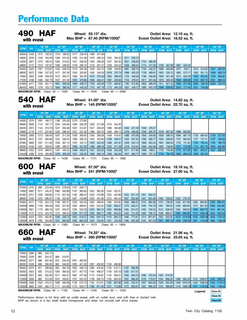
490 HAF Wheel: 55.13" dia. Outlet Area: 12.10 sq. ft. with evasé Max BHP = 87.40 (RPM/1000)3 Evasé Outlet Area: 18.52 sq. ft.
CFM OV18" SP 22" SP 26" SP 28" SP 30" SP 34" SP 38" SP 42" SP 46" SP 48" SP 50" SP
RPM BHP RPM BHP RPM BHP RPM BHP RPM BHP RPM BHP RPM BHP RPM BHP RPM BHP RPM BHP RPM BHP45000 2430 1212 150.22 1316 186.95 1417 226.43 1466 247.0949600 2678 1240 164.59 1336 201.62 1430 241.68 1476 262.54 1522 284.32 1611 329.1554200 2927 1273 180.44 1364 219.22 1451 259.39 1494 280.56 1537 302.65 1621 348.00 1704 396.0958800 3175 1310 197.67 1396 238.20 1479 280.19 1519 301.47 1559 323.53 1638 369.54 1715 417.29 1792 467.99 1867 520.4063400 3423 1351 216.87 1432 258.79 1510 302.09 1549 324.75 1586 346.82 1661 393.73 1734 442.27 1806 493.09 1877 545.7 1912 572.62 1947 600.2968000 3672 1394 237.52 1471 281.00 1545 325.82 1582 349.29 1618 372.74 1688 420.03 1758 469.91 1825 520.12 1892 573.17 1926 601.15 1959 628.7972600 3920 1438 259.30 1513 305.31 1584 352.00 1618 375.40 1652 399.45 1720 449.36 1786 500.00 1850 551.29 1914 605.09 1945 632.02 1976 659.6577200 4168 1484 282.79 1557 331.49 1625 379.86 1658 404.41 1691 429.63 1754 479.61 1817 531.84 1879 585.28 1940 639.99 1970 667.73 2001 696.1081800 4417 1530 307.11 1601 358.36 1668 409.72 1700 435.36 1731 460.87 1792 512.95 1852 566.53 1911 621.32 1969 677.06 2000 706.76 2028 734.7886400 4665 1578 333.73 1646 386.56 1711 440.34 1743 467.78 1773 494.28 1832 548.27 1890 603.78 1946 659.62 2003 717.44 2031 746.99
Performance Data
540 HAF Wheel: 61.00" dia. Outlet Area: 14.82 sq. ft. with evasé Max BHP = 145 (RPM/1000)3 Evasé Outlet Area: 22.70 sq. ft.
660 HAF Wheel: 74.25" dia. Outlet Area: 21.96 sq. ft. with evasé Max BHP = 390 (RPM/1000)3 Evasé Outlet Area: 33.65 sq. ft.
600 HAF Wheel: 67.50" dia. Outlet Area: 18.16 sq. ft. with evasé Max BHP = 241 (RPM/1000)3 Evasé Outlet Area: 27.80 sq. ft.
CFM OV18" SP 22" SP 26" SP 28" SP 30" SP 34" SP 38" SP 42" SP 46" SP 48" SP 50" SP
RPM BHP RPM BHP RPM BHP RPM BHP RPM BHP RPM BHP RPM BHP RPM BHP RPM BHP RPM BHP RPM BHP54000 2379 1091 180.71 1186 225.28 1279 273.8059600 2626 1115 197.71 1203 242.84 1290 292.30 1332 317.69 1374 344.2565200 2872 1144 216.76 1227 263.66 1307 312.87 1347 339.20 1386 365.88 1463 421.33 1538 479.3770800 3119 1177 237.63 1255 286.40 1331 337.46 1368 363.70 1404 390.13 1476 446.05 1548 505.75 1618 567.34 1686 630.9976400 3366 1213 260.40 1287 311.29 1358 363.60 1393 390.58 1428 418.42 1496 475.06 1563 534.60 1629 596.75 1694 661.10 1726 694.05 1758 727.9382000 3612 1251 284.96 1322 338.25 1389 392.23 1423 420.90 1456 449.47 1520 507.02 1583 566.77 1645 628.92 1707 694.63 1737 727.41 1767 760.9387600 3859 1291 311.65 1359 367.14 1423 423.15 1455 452.45 1486 481.61 1548 542.14 1608 603.42 1667 666.54 1725 731.62 1754 765.44 1782 798.7893200 4106 1331 339.04 1398 398.37 1460 457.05 1490 486.76 1520 517.28 1578 578.55 1636 642.56 1692 706.84 1747 772.56 1775 807.18 1804 842.8098800 4352 1373 368.91 1437 430.42 1498 492.61 1527 523.53 1556 555.28 1611 617.83 1666 683.2 1720 749.96 1773 817.82 1801 853.57 1827 888.34104400 4599 1416 400.86 1478 465.05 1537 530.03 1566 563.15 1593 594.94 1647 660.77 1699 727.10 1750 794.76 1803 866.43 1828 901.52
CFM OV18" SP 22" SP 26" SP 28" SP 30" SP 34" SP 38" SP 42" SP 46" SP 48" SP 50" SP
RPM BHP RPM BHP RPM BHP RPM BHP RPM BHP RPM BHP RPM BHP RPM BHP RPM BHP RPM BHP RPM BHP67000 2410 988 223.49 1074 278.92 1157 338.1774000 2662 1011 245.22 1090 300.88 1167 360.83 1205 392.36 1243 425.3181000 2914 1039 269.85 1113 327.50 1185 388.44 1220 419.98 1255 452.89 1324 521.13 1391 592.0788000 3165 1070 296.37 1139 355.92 1207 418.89 1240 451.06 1273 484.44 1337 552.68 1401 625.58 1463 700.22 1525 779.7995000 3417 1103 324.74 1169 387.37 1233 452.52 1265 486.64 1296 520.65 1356 589.37 1416 662.58 1475 739.02 1533 817.90 1562 858.92 1590 899.40102000 3669 1139 356.49 1202 421.84 1262 488.61 1292 523.55 1322 559.47 1379 630.21 1436 704.79 1491 780.54 1546 860.64 1573 901.29 1600 942.86109000 3921 1175 389.18 1237 459.07 1295 529.28 1323 564.74 1350 599.86 1405 674.07 1459 750.23 1512 828.45 1564 908.82 1589 948.70 1615 991.40116000 4173 1213 424.78 1273 498.42 1329 571.72 1356 608.71 1382 645.32 1434 721.28 1485 799.12 1536 880.07 1585 960.89 1610 1003.49 1635 1045.52123000 4424 1252 462.80 1309 538.73 1364 616.37 1390 654.73 1416 694.10 1466 772.81 1514 851.81 1562 933.95 1610 1018.99 1635 1063.09 1658 1105.52130000 4676 1292 503.68 1347 582.60 1400 663.50 1426 704.65 1451 745.29 1499 826.38 1545 907.62 1591 992.10 1638 1080.05 1661 1124.85 1683 1168.26
CFM OV18" SP 22" SP 26" SP 28" SP 30" SP 34" SP 38" SP 42" SP 46" SP 48" SP 50" SP
RPM BHP RPM BHP RPM BHP RPM BHP RPM BHP RPM BHP RPM BHP RPM BHP RPM BHP RPM BHP RPM BHP70000 2080 880 242.1075000 2229 887 254.37 969 319.9180000 2377 896 267.46 975 334.43 1051 405.9285000 2526 908 282.85 982 348.93 1055 421.05 1091 459.20 1126 498.0690000 2675 921 298.86 992 365.78 1062 438.73 1096 476.40 1130 515.71 1197 598.3895000 2823 935 315.52 1004 384.50 1071 457.75 1104 496.37 1136 535.10 1200 617.01100000 2972 950 332.85 1017 404.01 1081 477.48 1113 516.61 1144 556.01 1206 639.23 1266 725.04 1325 815.50110000 3269 985 372.59 1047 446.81 1107 523.76 1136 562.74 1165 603.03 1222 686.28 1278 773.67 1334 866.20 1389 962.29 1415 1009.37 1442 1060.10120000 3566 1022 415.41 1080 492.68 1136 572.73 1164 614.61 1192 657.68 1245 742.41 1297 830.20 1349 923.29 1400 1019.57 1425 1068.24 1450 1118.12130000 3863 1061 462.17 1117 544.68 1170 628.47 1196 671.49 1221 713.98 1272 803.91 1322 896.25 1370 988.98 1418 1086.38 1441 1134.62 1465 1186.50
Performance shown is for fans with an outlet evasé, with an outlet duct, and with free or ducted inlet.BHP as shown is a fan shaft brake horsepower and does not include belt drive losses.
Class 30Legend:
Class 50
Class 40
MAXIMUM RPM: Class 30 — 1592 Class 40 — 1926 Class 50 — 2060
MAXIMUM RPM: Class 30 — 1438 Class 40 — 1741 Class 50 — 1862
MAXIMUM RPM: Class 30 — 1300 Class 40 — 1573 Class 50 — 1800
MAXIMUM RPM: Class 30 — 1182 Class 40 — 1430 Class 50 — 1530
Twin City Catalog 1150 13
Performance Data
CFM OV18" SP 22" SP 26" SP 28" SP 30" SP 34" SP 38" SP 42" SP 46" SP 48" SP 50" SP
RPM BHP RPM BHP RPM BHP RPM BHP RPM BHP RPM BHP RPM BHP RPM BHP RPM BHP RPM BHP RPM BHP90000 2195 802 307.16 877 386.9495000 2317 808 319.70 880 399.79100000 2438 816 334.16 885 414.58 953 502.38 986 548.34105000 2560 824 348.31 891 429.86 957 518.89 989 564.97 1020 611.56110000 2682 834 364.71 899 447.51 962 536.11 993 582.54 1024 631.01 1084 730.76120000 2926 856 399.41 917 484.99 976 574.82 1005 621.87 1033 669.04 1090 770.50 1146 877.42130000 3170 881 437.70 938 526.01 994 619.13 1021 666.35 1048 715.34 1101 816.83 1153 922.92 1205 1035.62 1255 1150.37140000 3414 908 479.33 962 571.13 1015 667.74 1041 717.33 1066 766.34 1116 868.95 1165 975.87 1214 1089.61 1262 1206.57 1285 1264.49 1309 1326.95150000 3658 936 523.53 988 619.81 1038 719.16 1062 769.03 1087 822.44 1134 926.53 1181 1036.34 1227 1149.73 1272 1266.80 1294 1325.85 1317 1389.39160000 3901 965 570.72 1016 673.14 1063 774.44 1087 828.53 1110 881.86 1155 990.02 1199 1100.47 1243 1216.19 1286 1334.67 1307 1394.61 1328 1455.97
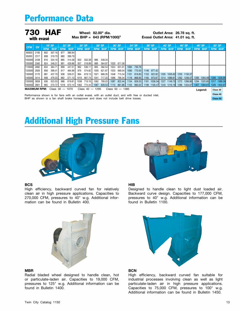
730 HAF Wheel: 82.00" dia. Outlet Area: 26.78 sq. ft. with evasé Max BHP = 643 (RPM/1000)3 Evasé Outlet Area: 41.01 sq. ft.
Additional High Pressure Fans
BCSHigh efficiency, backward curved fan for relatively clean air in high pressure applications. Capacities to 270,000 CFM, pressures to 40" w.g. Additional infor-mation can be found in Bulletin 400.
HIBDesigned to handle clean to light dust loaded air. Backward curve design. Capacities to 177,000 CFM, pressures to 40" w.g. Additional information can be found in Bulletin 1100.
MBRRadial bladed wheel designed to handle clean, hot or particulate-laden air. Capacities to 19,000 CFM, pressures to 125" w.g. Additional information can be found in Bulletin 1400.
Performance shown is for fans with an outlet evasé, with an outlet duct, and with free or ducted inlet.BHP as shown is a fan shaft brake horsepower and does not include belt drive losses.
Class 30Legend:
Class 50
Class 40
BCNHigh efficiency, backward curved fan suitable for industrial processes involving clean as well as light particulate-laden air in high pressure applications. Capacities to 75,000 CFM, pressures to 100" w.g. Additional information can be found in Bulletin 1450.
MAXIMUM RPM: Class 30 — 1070 Class 40 — 1295 Class 50 — 1385
Twin City Catalog 115014
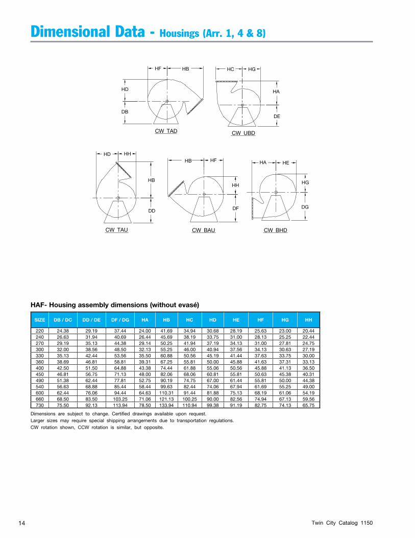
SIZE DB / DC DD / DE DF / DG HA HB HC HD HE HF HG HH
220 24.38 29.19 37.44 24.00 41.69 34.94 30.68 28.19 25.63 23.00 20.44240 26.63 31.94 40.69 26.44 45.69 38.19 33.75 31.00 28.13 25.25 22.44270 29.19 35.13 44.38 29.14 50.25 41.94 37.19 34.13 31.00 27.81 24.75300 32.00 38.56 48.50 32.13 55.25 46.00 40.94 37.56 34.13 30.63 27.19330 35.13 42.44 53.56 35.50 60.88 50.56 45.19 41.44 37.63 33.75 30.00360 38.69 46.81 58.81 39.31 67.25 55.81 50.00 45.88 41.63 37.31 33.13400 42.50 51.50 64.88 43.38 74.44 61.88 55.06 50.56 45.88 41.13 36.50450 46.81 56.75 71.13 48.00 82.06 68.06 60.81 55.81 50.63 45.38 40.31490 51.38 62.44 77.81 52.75 90.19 74.75 67.00 61.44 55.81 50.00 44.38540 56.63 68.88 85.44 58.44 99.63 82.44 74.06 67.94 61.69 55.25 49.00600 62.44 76.06 94.44 64.63 110.31 91.44 81.88 75.13 68.19 61.06 54.19660 68.50 83.50 103.25 71.06 121.13 100.25 90.00 82.56 74.94 67.13 59.56730 75.50 92.13 113.94 78.50 133.94 110.94 99.38 91.19 82.75 74.13 65.75
Dimensional Data - Housings (Arr. 1, 4 & 8)
DD
HD HH
HB
CW TAU CW BAU
HB
CW BHD
CW UBDCW TAD
HH
HD
HB
DE
DF DG
HG
HEHAHF
HF
HA
HGHC
DB
HAF- Housing assembly dimensions (without evasé)
Dimensions are subject to change. Certified drawings available upon request.Larger sizes may require special shipping arrangements due to transportation regulations.CW rotation shown, CCW rotation is similar, but opposite.

Twin City Catalog 1150 15
SIZE A B BH C CC DC EF EH EW G GA GC H HA HC HE J
220 27.69 13.69 0.81 19.50 24.25 24.38 7.19 31.63 42.00 35.38 0.25 17.69 35.63 24.00 34.94 28.19 8.91240 30.38 15.00 0.81 21.25 26.25 26.63 7.88 34.81 46.19 38.00 0.25 19.00 38.56 26.44 38.19 31.00 9.59270 33.50 16.50 0.81 23.50 29.00 29.19 8.75 38.44 50.94 42.00 0.25 21.00 40.50 29.19 41.94 34.13 10.68300 36.88 18.19 0.81 26.00 30.50 32.00 9.63 42.38 56.13 46.00 0.25 23.00 42.88 32.13 46.00 37.56 11.51330 40.69 20.00 0.81 28.75 33.00 35.13 10.69 46.81 62.00 50.00 0.25 25.00 45.75 35.50 50.56 41.44 12.53360 45.06 22.13 1.06 31.75 36.25 38.69 11.81 51.88 68.69 56.00 0.25 28.00 51.19 39.31 55.81 45.88 13.84400 49.69 24.38 1.06 35.00 39.75 42.50 13.06 57.25 75.75 61.00 0.25 30.50 54.19 43.38 61.88 50.56 15.13450 54.88 26.88 1.06 38.50 45.25 46.81 14.44 63.25 83.75 68.50 0.25 34.25 61.75 48.00 68.06 55.81 16.61490 60.44 29.56 1.06 42.75 49.50 51.38 15.94 69.75 92.25 76.50 0.25 38.25 67.81 52.75 74.75 61.44 18.27540 66.81 32.69 1.06 47.00 53.50 56.63 17.63 77.19 102.06 83.50 0.25 41.75 72.69 58.44 82.44 67.94 20.38600 73.88 36.13 1.06 52.25 57.75 62.44 19.50 85.38 112.88 91.00 0.25 45.50 78.13 64.63 91.44 75.13 22.47660 81.19 39.69 1.06 57.50 63.00 68.50 21.50 93.94 124.13 99.00 0.25 49.50 81.06 71.06 100.25 82.56 24.79730 89.75 43.88 1.06 63.50 70.00 75.50 23.69 103.75 137.13 108.00 0.31 54.00 88.63 78.50 110.94 91.19 27.34
Dimensional Data - Arrangement 1
HE HA
HC EF
EHEVASE HEIGHT
EW x B
“GA” THKHSG SIDES
AND SCROLL
GCG
DC
CL
CL
SHAFT
DISCH
QEVASE
CL
OPTIONAL EVASESHOWN IN ONE VIEWFOR SIMPLICITY
“SD” DIA.SHAFT
“KS” KWY SIZE
N
SE
DX
JP
KL B
A
CLHSG
CCO.D.
FLANGE
OUTSIDE HSG.
OUTS
IDE H
SG.
HCW THD
MF
KB
KA K
MA
K
MA
MF
CLHSG
CL SHAFT
“BH” DIA.HOLES
(T) SPACES@ “L”
FOUNDATION VIEW
Dimensions are subject to change. Certified drawings available upon request.Larger sizes may require special shipping arrangements due to transportation regulations.
Notes:1. CW rotation is shown. CCW rotation is similar, but opposite.2. Split housing is required on Sizes 360 and larger. Split bars may
extend past housing.
SIZE K KA KB KLKS
L T MA MF P Q SE30 40 50
220 8.38 4.75 2.38 7.00 0.50 x 0.25 0.50 x 0.25 0.50 x 0.25 10.25 1 16.19 5.50 33.75 19.06 8.00240 9.00 4.75 2.38 7.13 0.63 x 0.31 0.63 x 0.31 0.63 x 0.31 11.94 1 17.50 5.50 36.31 21.00 8.25270 9.75 4.75 2.38 7.13 0.63 x 0.31 0.63 x 0.31 0.63 x 0.31 12.38 1 19.50 6.50 37.50 23.19 8.25300 10.63 4.75 2.38 7.50 0.63 x 0.31 0.75 x 0.38 0.75 x 0.38 13.00 1 21.50 6.50 39.50 25.56 8.75330 11.50 5.75 2.38 7.69 0.75 x 0.38 0.88 x 0.44 0.88 x 0.44 13.13 1 23.50 7.50 41.75 28.25 9.00360 13.06 6.25 2.88 7.63 0.88 x 0.44 0.88 x 0.44 1.00 x 0.50 13.94 1 26.00 7.50 45.13 31.25 9.00400 14.19 6.25 2.88 8.63 0.88 x 0.44 1.00 x 0.50 1.00 x 0.50 14.69 1 28.50 10.50 48.00 34.56 10.00450 16.44 6.25 2.88 8.63 1.00 x 0.50 1.00 x 0.50 1.00 x 0.50 8.88 2 32.25 11.50 53.31 38.13 10.00490 18.75 6.25 3.00 9.63 1.00 x 0.50 1.00 x 0.50 1.00 x 0.50 9.50 2 36.25 12.50 58.06 42.06 11.00540 20.38 7.25 3.00 9.50 1.00 x 0.50 1.25 x 0.63 1.25 x 0.63 9.88 2 39.75 13.50 61.31 46.56 11.00600 22.06 7.25 3.00 10.25 1.25 x 0.63 1.25 x 0.63 1.25 x 0.63 10.88 2 43.50 14.50 65.81 51.50 11.75660 23.88 7.25 3.00 10.50 1.25 x 0.63 1.25 x 0.63 1.25 x 0.63 10.50 2 47.50 14.50 67.19 56.63 12.00730 25.94 8.25 3.00 10.50 1.25 x 0.63 1.25 x 0.63 1.25 x 0.63 11.75 2 52.00 15.50 72.69 62.56 12.00
BC1002590
Twin City Catalog 115016
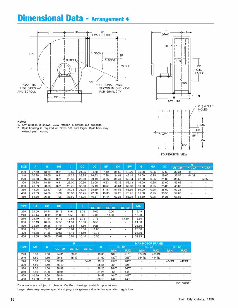
SIZE A B BH C CC DC EF EH EW G GA GCH
CL - 30 CL- 40 CL- 50 220 27.69 13.69 0.81 19.50 24.25 24.38 7.19 31.63 42.00 35.38 0.25 17.69 30.31 41.19 -240 30.38 15.00 0.81 21.25 26.25 26.63 7.88 34.81 46.19 38.00 0.25 19.00 35.56 44.31 -270 33.50 16.50 0.81 23.50 29.00 29.19 8.75 38.44 50.94 42.00 0.25 21.00 38.63 - 50.50300 36.88 18.19 0.81 26.00 30.50 32.00 9.63 42.38 56.13 46.00 0.25 23.00 42.06 - -330 40.69 20.00 0.81 28.75 33.00 35.13 10.69 46.81 62.00 50.00 0.25 25.00 45.00 - -360 45.06 22.13 1.06 31.75 36.25 38.69 11.81 51.88 68.69 56.00 0.25 28.00 52.25 - -400 49.69 24.38 1.06 35.00 39.75 42.50 13.06 57.25 75.75 61.00 0.25 30.50 59.00 - -450 54.88 26.88 1.06 38.50 45.25 46.81 14.44 63.25 83.75 68.50 0.25 34.25 67.88 - -
SIZE HA HC HE J KL
MACL - 30 CL- 40 CL- 50
220 24.00 34.94 28.19 8.91 8.38 5.00 10.00 - 16.19240 26.44 38.19 31.00 9.59 9.00 7.00 11.00 - 17.50270 29.19 41.94 34.13 10.68 9.75 7.75 - 13.50 19.50300 32.13 46.00 37.56 11.51 10.63 8.50 - - 21.50330 35.50 50.56 41.44 12.53 11.50 9.25 - - 23.50360 39.31 55.81 45.88 13.84 13.06 11.00 - - 26.00400 43.38 61.88 50.56 15.13 14.19 13.75 - - 28.50450 48.00 68.06 55.81 16.61 16.44 15.50 - - 32.25
Dimensional Data - Arrangement 4
SIZE MF NP
QMAX MOTOR FRAME
CL - 30 CL- 40 CL- 50 CL- 30 CL- 40 CL- 50
MIN MAX MIN MAX MIN MAX220 5.50 1.50 24.31 39.63 - 19.06 182T 215T 324TS 405TS - -240 5.50 1.50 29.81 45.13 - 21.00 182T 256T 364TS 444TS - -270 6.50 1.50 32.88 - 54.00 23.19 254T 286T - - 404TS 447TS300 6.50 1.50 36.19 - - 25.56 254T 326T - - - -330 7.50 1.50 38.88 - - 28.25 284T 365T - - - -360 7.50 2.00 49.94 - - 31.25 364T 444T - - - -400 10.50 2.00 60.44 - - 34.56 404T 447T - - - -450 11.50 2.00 62.06 - - 38.13 444T 449T - - - -
Dimensions are subject to change. Certified drawings available upon request.Larger sizes may require special shipping arrangements due to transportation regulations.
HE HA
HC EF
EHEVASE HEIGHT
EW x B
“GA” THKHSG SIDES
AND SCROLL
GCG
DC
CL
CL
SHAFT
DISCH
EVASE
N
DX
JP(MAX)
A
CCO.D.
FLANGE
OUTS
IDE H
SG.
HCW THD
MF
MA
MA
MF
CLHSG
CL SHAFT
(10) “BH”HOLES
FOUNDATION VIEW
CL
OPTIONAL EVASESHOWN IN ONE VIEWFOR SIMPLICITY
B
CLHSG
OUTSIDE HSG.
Notes:1. CW rotation is shown. CCW rotation is similar, but opposite.2. Split housing is required on Sizes 360 and larger. Split bars may
extend past housing.
BC1002591
Twin City Catalog 1150 17
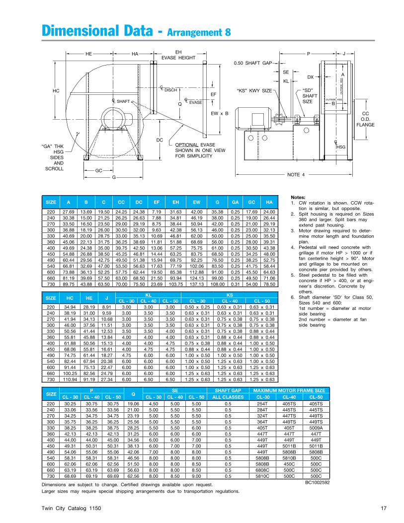
SIZE A B C CC DC EF EH EW G GA GC HA
220 27.69 13.69 19.50 24.25 24.38 7.19 31.63 42.00 35.38 0.25 17.69 24.00240 30.38 15.00 21.25 26.25 26.63 7.88 34.81 46.19 38.00 0.25 19.00 26.44270 33.50 16.50 23.50 29.00 29.19 8.75 38.44 50.94 42.00 0.25 21.00 29.19300 36.88 18.19 26.00 30.50 32.00 9.63 42.38 56.13 46.00 0.25 23.00 32.13330 40.69 20.00 28.75 33.00 35.13 10.69 46.81 62.00 50.00 0.25 25.00 35.50360 45.06 22.13 31.75 36.25 38.69 11.81 51.88 68.69 56.00 0.25 28.00 39.31400 49.69 24.38 35.00 39.75 42.50 13.06 57.25 75.75 61.00 0.25 30.50 43.38450 54.88 26.88 38.50 45.25 46.81 14.44 63.25 83.75 68.50 0.25 34.25 48.00490 60.44 29.56 42.75 49.50 51.38 15.94 69.75 92.25 76.50 0.25 38.25 52.75540 66.81 32.69 47.00 53.50 56.63 17.63 77.19 102.06 83.50 0.25 41.75 58.44600 73.88 36.13 52.25 57.75 62.44 19.50 85.38 112.88 91.00 0.25 45.50 64.63660 81.19 39.69 57.50 63.00 68.50 21.50 93.94 124.13 99.00 0.25 49.50 71.06730 89.75 43.88 63.50 70.00 75.50 23.69 103.75 137.13 108.00 0.31 54.00 78.50
SIZE HC HE JKL KS
CL - 30 CL - 40 CL - 50 CL - 30 CL - 40 CL - 50220 34.94 28.19 8.91 3.00 3.00 3.00 0.50 x 0.25 0.63 x 0.31 0.63 x 0.31240 38.19 31.00 9.59 3.00 3.50 3.50 0.63 x 0.31 0.63 x 0.31 0.63 x 0.31270 41.94 34.13 10.68 3.00 3.50 3.50 0.63 x 0.31 0.75 x 0.38 0.75 x 0.38300 46.00 37.56 11.51 3.00 3.50 3.50 0.63 x 0.31 0.75 x 0.38 0.75 x 0.38330 50.56 41.44 12.53 3.50 3.50 4.00 0.63 x 0.31 0.75 x 0.38 0.88 x 0.44360 55.81 45.88 13.84 4.00 4.00 4.00 0.63 x 0.31 0.88 x 0.44 0.88 x 0.44400 61.88 50.56 15.13 4.00 4.00 4.75 0.75 x 0.38 0.88 x 0.44 1.00 x 0.50450 68.06 55.81 16.61 4.00 4.75 4.75 0.88 x 0.44 0.88 x 0.44 1.00 x 0.50490 74.75 61.44 18.27 4.75 6.00 6.00 1.00 x 0.50 1.00 x 0.50 1.00 x 0.50540 82.44 67.94 20.38 6.00 6.00 6.00 1.00 x 0.50 1.25 x 0.63 1.00 x 0.50600 91.44 75.13 22.47 6.00 6.00 6.00 1.00 x 0.50 1.25 x 0.63 1.25 x 0.63660 100.25 82.56 24.79 6.00 6.00 6.00 1.25 x 0.63 1.25 x 0.63 1.25 x 0.63730 110.94 91.19 27.34 6.00 6.50 6.50 1.25 x 0.63 1.25 x 0.63 1.25 x 0.63
Dimensional Data - Arrangement 8
SIZEP
QSE SHAFT GAP MAXIMUM MOTOR FRAME SIZE
CL - 30 CL - 40 CL - 50 CL - 30 CL - 40 CL - 50 ALL CLASSES CL-30 CL-40 CL-50220 30.25 30.75 30.75 19.06 4.50 5.00 5.00 0.5 254T 405TS 405TS240 33.06 33.56 33.56 21.00 5.00 5.50 5.50 0.5 284T 445TS 445TS270 34.25 34.75 34.75 23.19 5.00 5.50 5.50 0.5 324T 447TS 449TS300 35.75 36.25 36.25 25.56 5.00 5.50 5.50 0.5 364T 449TS 449TS330 38.25 38.25 38.75 28.25 5.50 5.50 6.00 0.5 405T 405T 5009A360 42.13 42.13 42.13 31.25 6.00 6.00 6.00 0.5 447T 447T 447T400 44.00 44.00 45.00 34.56 6.00 6.00 7.00 0.5 449T 449T 449T 450 49.31 50.31 50.31 38.13 6.00 7.00 7.00 0.5 449T 5011B 5011B490 54.06 55.06 55.06 42.06 7.00 8.00 8.00 0.5 449T 5808B 5808B540 58.31 58.31 58.31 46.56 8.00 8.00 8.00 0.5 5808B 5810B 500C600 62.06 62.06 62.56 51.50 8.00 8.00 8.50 0.5 5808B 450C 500C660 63.19 63.19 63.69 56.63 8.00 8.00 8.50 0.5 6808C 500C 500C730 68.69 69.19 69.69 62.56 8.00 8.50 9.00 0.5 5810C 500C 500C
Dimensions are subject to change. Certified drawings available upon request.Larger sizes may require special shipping arrangements due to transportation regulations.
Notes:1. CW rotation is shown. CCW rota-
tion is similar, but opposite.2. Split housing is required on Sizes
360 and larger. Split bars may extend past housing.
3. Motor drawing required to deter-mine motor length and foundation plan.
4. Pedestal will need concrete with grillage if motor HP > 1000 or if fan centerline height > 90". Motor and grillage to be mounted on concrete pier provided by others.
5. Steel pedestal to be filled with concrete if HP > 400, or at engi-neer's discretion. Concrete by others.
6. Shaft diameter 'SD' for Class 50, Sizes 540 and 600:
1st number = diameter at motor side bearing
2nd number = diameter at fan side bearing
BC1002592
HE HA
HCEF
EHEVASE HEIGHT
EW x B
“GA” THKHSG
SIDESAND
SCROLL GCG
DC
C
CL
SHAFT
DISCH
EVASE
DX
JP
CCO.D.
FLANGE
NOTE 4
CL
OPTIONAL EVASESHOWN IN ONE VIEWFOR SIMPLICITY
CLHSG
L Q
A
OUTS
IDE H
SG.
BOUTSIDE HSG.
0.50 SHAFT GAP
“KS” KWY SIZE
SE
KL
“SD”SHAFTSIZE

Twin City Catalog 115018
SIZE CC BC NH DHFLANGE
WIDTH220 24.25 22.50 12 0.56 2.38240 26.25 24.50 16 0.56 2.50270 29.00 27.25 16 0.56 2.75300 30.50 28.00 16 0.56 2.25330 33.00 30.75 16 0.56 2.13360 36.25 33.75 24 0.56 2.25400 39.75 37.00 32 0.56 2.38450 45.25 42.50 32 0.56 3.38490 49.50 46.00 40 0.69 3.38540 53.50 51.00 40 0.69 3.25600 57.75 55.50 40 0.69 2.75660 63.00 60.00 40 0.69 2.75730 70.00 66.50 48 0.69 3.25
BC
CC
INLET FLANGE
(NH) DH HOLES
SIZE A B EW DH EG EN FF FE FG FH FNHN
DXFAN EVASÉ
220 27.69 13.69 42.00 0.56 4.63 7 2 0.88 4.94 3.00 4 16 22 2.00240 30.38 15.00 46.19 0.56 4.25 8 2 0.88 3.81 3.63 5 18 24 2.00270 33.50 16.50 50.94 0.56 4.06 9 2 0.88 5.38 4.38 5 18 26 2.00300 36.88 18.19 56.13 0.56 4.19 10 3 0.88 4.56 2.75 6 22 30 2.00330 40.69 20.00 62.00 0.56 4.63 11 3 0.88 3.94 3.63 7 24 32 2.00360 45.06 22.13 68.69 0.56 3.00 13 3 0.88 3.63 4.69 8 26 36 2.00400 49.69 24.38 75.75 0.56 4.25 14 4 1.13 3.69 3.56 9 30 40 2.50450 54.88 26.88 83.75 0.56 3.25 16 4 1.13 3.81 4.81 10 32 44 2.50490 60.44 29.56 92.25 0.69 5.00 17 5 1.13 4.06 3.63 11 36 48 2.50540 66.81 32.69 102.06 0.69 4.94 19 5 1.13 4.75 5.19 12 38 52 2.50600 73.88 36.13 112.88 0.69 3.06 22 6 1.38 3.56 4.69 14 44 60 3.00660 81.19 39.69 124.13 0.69 3.69 24 7 1.38 4.75 4.00 15 48 66 3.00730 89.75 43.88 137.13 0.69 2.94 27 8 1.63 4.25 3.81 17 54 74 3.50
FE (TYP)
FG
FN SPACES@ 5.00
DX
FH
B
FF SP.@ 5.00
DH HOLES
OUTLET FLANGE DETAIL EVASE OUTLET FLANGE DETAIL
INSIDEANGLES
EN SPACES@ 5.00
DH HOLES
DX
FHFF SP.@ 5.00FE (TYP)
EG
EW
BINSIDEANGLES
(HN)
(HN)
Flanged Inlet Dimensions
Flanged Outlet and Evasé Dimensions
Furnished as standard
Dimensional Data - Inlet & Outlet Flanges
Dimensions are subject to change. Certified drawings available upon request.
Outlet flange furnished as standard

Twin City Catalog 1150 19
Typical SpecificationsFurnish and install as indicated on the plans, Twin City Fan and Blower model HAF industrial duty airfoil fans.
HOUSING — Fan housings shall be made of heavy-gauge steel with continuously welded construction and braced with structural shapes to eliminate any resonant vibration and provide smooth operation. Sizes 360 and larger will be furnished with a pie-shaped split as standard. The housing split shall be fully gasketed and bolted together to prevent any leaks. Flanged inlet and outlet shall be provided as standard equipment. Bearing sup-port members shall be fabricated of heavy steel shapes or made of concrete to ensure maximum rigidity.
WHEEL — Blade design shall be airfoil for high efficiency and have non-overloading performance characteris-tics. Blades shall be die-formed of special alloy material for strength and accuracy of contour and continuously welded to the wheel inlet cone and backplate. A heavy fabricated steel (not cast iron) hub shall be provided. Wheels shall be shrunk fit on the shafts, and hubs shall include puller holes for use in the event of wheel removal. Wheels shall be statically and dynamically balanced on precision electronic machines, as well as bal-ance tuned after complete assembly.
SHAFT — Shafts are to be solid AISI 1040 or 1045 hot rolled steel, accurately turned, ground, polished, and ring gauged for accuracy.
BEARINGS — Fans shall be supplied with heavy duty, self-aligning, grease lubricated, anti-friction, pillow block type bearings selected for a minimum average bearing life (AFBMA L-50) in excess of 200,000 hours at the maximum fan RPM. Sizes 220 through 540 are supplied with ball or roller bearings. Sizes 600 through 730 are supplied with spherical roller bearings with split pillow block housings. Where required, sleeve bearings may be used with appropriate cooling method for high carrying loads.
DRIVE — Motor and fan sheaves shall be cast iron. Drives and belts are to be located external to the fan casing and rated for 150% of the required motor HP.
FINISH & COATING — The entire assembly, excluding the shaft, shall be thoroughly degreased and deburred before application of a protective coating which is applied to the entire assembly. The fan shaft should be coated with a petroleum-based rust protectant.
ACCESSORIES — When specified, accessories such as belt guards, access doors, companion flanges, variable inlet vanes, outlet dampers, inlet boxes, inlet box dampers, evasés, evasé dampers, shaft coolers, shaft seals, closure plates, inlet screens, drains, etc., shall be provided by Twin City Fan & Blower to maintain one source responsibility.
FACTORY TEST RUN — All fans prior to shipment shall be completely assembled and test run as a unit at operating speed or maximum RPM allowed for the particular construction type. Each wheel shall be statically and dynamically balanced to balance grade G6.3 or better per ANSI S2.19. Balance readings shall be taken using electronic type equipment and records shall be maintained of the readings of axial, vertical, and horizontal direction on each of the bearings. A written copy of this record shall be available upon request.
GUARANTEE — Manufacturer shall guarantee the workmanship and materials for its High Pressure Industrial Airfoil Bladed Fans for at least one (1) year from startup or eighteen (18) months from shipment, whichever occurs first.

TWIN CITY FAN & BLOWERWWW.TCF.COM
5959 TRENTON LANE N | MINNEAPOLIS, MN 55442 | PHONE: 763-551-7600 | FAX: 763-551-7601
CENTRIFUGAL FANS | UTILITY SETS | PLENUM & PLUG FANS | INLINE CENTRIFUGAL FANS
MIXED FLOW FANS | TUBEAXIAL & VANEAXIAL FANS | PROPELLER WALL FANS | PROPELLER ROOF VENTILATORS
CENTRIFUGAL ROOF & WALL EXHAUSTERS | CEILING VENTILATORS | GRAVITY VENTILATORS | DUCT BLOWERS
RADIAL BLADED FANS | RADIAL TIP FANS | HIGH EFFICIENCY INDUSTRIAL FANS | PRESSURE BLOWERS
LABORATORY EXHAUST FANS | FILTERED SUPPLY FANS | MANCOOLERS | FIBERGLASS FANS | CUSTOM FANS
INDUSTRIAL PROCESS ANDCOMMERCIAL VENTILATION SYSTEMS
©2018 Twin City Fan Companies, Ltd., Minneapolis, MN. All rights reserved. Catalog illustrations cover the general appearance of Twin City
Fan & Blower products at the time of publication and we reserve the right to make changes in design and construction at any time without notice.
Twin City Fan
Twin City Fan


![Effect of Gurney Flap on Airfoil Lift Coefficient by Design of …jast.modares.ac.ir/article-15-20880-fa.pdf · of Gurney flap on SFYT15thick airfoil [19] Aerodynamic efficiency study](https://static.fdocuments.us/doc/165x107/60bd5a358e42e2274f7a1aaf/effect-of-gurney-flap-on-airfoil-lift-coefficient-by-design-of-jast-of-gurney-flap.jpg)


