High Efficiency Bicycle Propulsion System Using Two … · High Efficiency Bicycle Propulsion...
8
EVS24 Stavanger, Norway, May 13-16, 2009 High Efficiency Bicycle Propulsion System Using Two Motors and Epicyclic Gearing Per H. Sørensen 1 , Miles Hellon 2 1 Forsandveien 13, 4307 Sandnes, Norway, [email protected] 2 38 Winforton Street, London SE10 8UR, U.K., [email protected] Abstract This paper describes a novel propulsion unit for cycles and other ultralight vehicles using two brushless DC (BLDC) motors feeding sun and ring gear of an epicyclic gear unit all within a single enclosure. The two BLDC motors having different operating characteristics are being actively managed using a microprocessor connected to two electronic commutation controllers, one for each motor. By optimizing the RPM for each motor according to vehicle speed and torque the main propulsion motor and its controller is kept working within its maximum efficiency band. Most of the electric energy is used by this motor and controller pair maintaining total efficiency at a high level. Keywords: bicycle, brushless motor, efficiency, planetary gear, powertrain 1 Introduction The single biggest obstacle for electric vehicles is the high cost of energy storage, both in terms of investment and in added weight to the vehicle [1]. For shorter distances electric bicycles are a smart choice as their energy requirement is much less than a car-sized electric vehicle [2][3]. They are now used in large numbers but mostly on flat terrain [4]. As a commuter vehicle for hilly terrain electric bicycles need refinement. This paper discuss a propulsion unit for electric bicycles and other ultralight electric vehicles that increases the efficiency and versatility of the powertrain by adding a electromechanical variable gearing. 1.1 Current Electric Bicycle Motors Currently, most commercial electric bicycle motors are hub motors with or without a fixed gearing. Alternatively, some motors are part of the pedal arrangement and their power is transferred to the wheel using the same bicycle chain as the cyclist. Sometimes friction drive, direct to the tyre or rim, is used. All the existing solutions involves some form of compromise as can be seen from table 1. 1.2 Lack of Gearing Of the commercially used motor solutions, only those which drive via the bicycle's chain can be geared. The other solutions use a single gear or drive the wheel directly. Gearing is important to match the RPM band where the motor is efficient with the speed of the bicycle which depends on the available motor power and the current road condition and bicycle load. With limited power available due to legal reasons and battery range issues, the lack of gearing is an important limitation, especially in hilly terrain [5]. EVS24 International Battery, Hybrid and Fuel Cell Electric Vehicle Symposium 1
Transcript of High Efficiency Bicycle Propulsion System Using Two … · High Efficiency Bicycle Propulsion...
EVS24Stavanger, Norway, May 13-16, 2009
High Efficiency Bicycle Propulsion System Using TwoMotors and Epicyclic Gearing
Per H. Sørensen1, Miles Hellon2
1Forsandveien 13, 4307 Sandnes, Norway, [email protected] Winforton Street, London SE10 8UR, U.K., [email protected]
Abstract
This paper describes a novel propulsion unit for cycles and other ultralight vehicles using two brushless DC
(BLDC) motors feeding sun and ring gear of an epicyclic gear unit all within a single enclosure. The two
BLDC motors having different operating characteristics are being actively managed using a microprocessor
connected to two electronic commutation controllers, one for each motor. By optimizing the RPM for each
motor according to vehicle speed and torque the main propulsion motor and its controller is kept working
within its maximum efficiency band. Most of the electric energy is used by this motor and controller pair
maintaining total efficiency at a high level.
Keywords: bicycle, brushless motor, efficiency, planetary gear, powertrain
1 IntroductionThe single biggest obstacle for electric vehicles isthe high cost of energy storage, both in terms ofinvestment and in added weight to the vehicle [1].
For shorter distances electric bicycles are a smartchoice as their energy requirement is much lessthan a car-sized electric vehicle [2][3]. They arenow used in large numbers but mostly on flatterrain [4].
As a commuter vehicle for hilly terrain electricbicycles need refinement. This paper discuss apropulsion unit for electric bicycles and otherultralight electric vehicles that increases theefficiency and versatility of the powertrain byadding a electromechanical variable gearing.
1.1 Current Electric Bicycle Motors Currently, most commercial electric bicyclemotors are hub motors with or without a fixed
gearing. Alternatively, some motors are part ofthe pedal arrangement and their power istransferred to the wheel using the same bicyclechain as the cyclist. Sometimes friction drive,direct to the tyre or rim, is used. All the existingsolutions involves some form of compromise ascan be seen from table 1.
1.2 Lack of GearingOf the commercially used motor solutions, onlythose which drive via the bicycle's chain can begeared. The other solutions use a single gear ordrive the wheel directly.Gearing is important to match the RPM bandwhere the motor is efficient with the speed of thebicycle which depends on the available motorpower and the current road condition and bicycleload.With limited power available due to legal reasonsand battery range issues, the lack of gearing is animportant limitation, especially in hilly terrain [5].
EVS24 International Battery, Hybrid and Fuel Cell Electric Vehicle Symposium 1
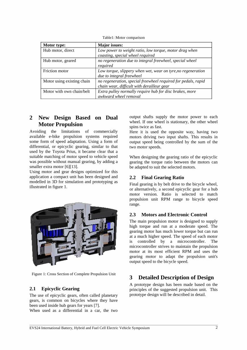
Table1: Motor comparison
Motor type: Major issues:Hub motor, direct Low power to weight ratio, low torque, motor drag when
coasting, special wheel requiredHub motor, geared no regeneration due to integral freewheel, special wheel
requiredFriction motor Low torque, slippery when wet, wear on tyre,no regeneration
due to integral freewheelMotor using existing chain no regeneration, special freewheel required for pedals, rapid
chain wear, difficult with derailleur gearMotor with own chain/belt Extra pulley normally require hub for disc brakes, more
awkward wheel removal
2 New Design Based on DualMotor Propulsion
Avoiding the limitations of commerciallyavailable e-bike propulsion systems requiredsome form of speed adaptation. Using a form ofdifferential, or epicyclic gearing, similar to thatused by the Toyota Prius, it became clear that asuitable matching of motor speed to vehicle speedwas possible without manual gearing, by adding asmaller extra motor [6][13]. Using motor and gear designs optimized for thisapplication a compact unit has been designed andmodelled in 3D for simulation and prototyping asillustrated in figure 1.
2.1 Epicyclic GearingThe use of epicyclic gears, often called planetarygears, is common on bicycles where they havebeen used inside hub gears for years [7].When used as a differential in a car, the two
output shafts supply the motor power to eachwheel. If one wheel is stationary, the other wheelspins twice as fast. Here it is used the opposite way, having twomotors driving two input shafts. This results inoutput speed being controlled by the sum of thetwo motor speeds.
When designing the gearing ratio of the epicyclicgearing the torque ratio between the motors canbe adapted to suit the selected motors.
2.2 Final Gearing RatioFinal gearing is by belt drive to the bicycle wheel,or alternatively, a second epicyclic gear for a hubmotor version. Ratio is selected to matchpropulsion unit RPM range to bicycle speedrange.
2.3 Motors and Electronic ControlThe main propulsion motor is designed to supplyhigh torque and run at a moderate speed. Thegearing motor has much lower torque but can runat a much higher speed. The speed of each motoris controlled by a microcontroller. Themicrocontroller strives to maintain the propulsionmotor at its most efficient RPM and uses thegearing motor to adapt the propulsion unit'soutput speed to the bicycle speed.
3 Detailed Description of DesignA prototype design has been made based on theprinciples of the suggested propulsion unit. Thisprototype design will be described in detail.
EVS24 International Battery, Hybrid and Fuel Cell Electric Vehicle Symposium 2
Figure 1: Cross Section of Complete Propulsion Unit
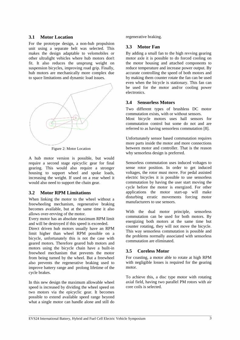
3.1 Motor LocationFor the prototype design, a non-hub propulsionunit using a separate belt was selected. Thismakes the design adaptable to velomobiles orother ultralight vehicles where hub motors don'tfit. It also reduces the unsprung weight onsuspension bicycles, improving road grip. Finally,hub motors are mechanically more complex dueto space limitations and dynamic load issues.
Figure 2: Motor Location
A hub motor version is possible, but wouldrequire a second stage epicyclic gear for finalgearing. This would also require a strongerhousing to support wheel and spoke loads,increasing the weight. If used on a rear wheel itwould also need to support the chain gear.
3.2 Motor RPM Limitations When linking the motor to the wheel without afreewheeling mechanism, regenerative brakingbecomes available, but at the same time it alsoallows over-revving of the motor.Every motor has an absolute maximum RPM limitand will be destroyed if this speed is exceeded.Direct driven hub motors usually have an RPMlimit higher than wheel RPM possible on abicycle, unfortunately this is not the case withgeared motors. Therefore geared hub motors andmotors using the bicycle chain have a built-infreewheel mechanism that prevents the motorfrom being turned by the wheel. But a freewheelalso prevents the regenerative braking used toimprove battery range and prolong lifetime of thecycle brakes.
In this new design the maximum allowable wheelspeed is increased by dividing the wheel speed ontwo motors via the epicyclic gear. It becomespossible to extend available speed range beyondwhat a single motor can handle alone and still do
regenerative braking.
3.3 Motor FanBy adding a small fan to the high revving gearingmotor axle it is possible to do forced cooling onthe motor housing and attached components toreduce temperature and increase power output. Byaccurate controlling the speed of both motors andby making them counter rotate the fan can be usedeven when the bicycle is stationary. This fan canbe used for the motor and/or cooling powerelectronics.
3.4 Sensorless MotorsTwo different types of brushless DC motorcommutation exists, with or without sensors. Most bicycle motors uses hall sensors forcommutation control but some do not and arereferred to as having sensorless commutation [8].
Unfortunately sensor based commutation requiresmore parts inside the motor and more connectionsbetween motor and controller. That is the reasonwhy sensorless design is preferred. Sensorless commutation uses induced voltages tosense rotor position. In order to get inducedvoltages, the rotor must move. For pedal assistedelectric bicycles it is possible to use sensorlesscommutation by having the user start moving thecycle before the motor is energized. For otherapplications the motor start-up will makedisturbing erratic movements forcing motormanufacturers to use sensors.
With the dual motor principle, sensorlesscommutation can be used for both motors. Byenergizing both motors at the same time butcounter rotating, they will not move the bicycle.This way sensorless commutation is possible andthe problems normally associated with sensorlesscommutation are eliminated.
3.5 Coreless MotorFor coasting, a motor able to rotate at high RPMwith negligible losses is required for the gearingmotor. To achieve this, a disc type motor with rotatingaxial field, having two parallel PM rotors with aircore coils is selected.
EVS24 International Battery, Hybrid and Fuel Cell Electric Vehicle Symposium 3

3.6 Reduction of LossWhen a permanent magnet motor is forced torotate it will induce voltage in the windings.Rotation will also cause eddy current losses in allconductors exposed to moving magnetic fields. By removing the laminated metal stator thelargest cause of eddy losses is removed.
In addition some eddy current losses occur insidethe stator coil. This is reduced by using thinmagnet wire in parallel to get required crosssection, so called litz wire. Alternatively, thewindings may be made of thin metal foil that isinsulated and rolled to a coil.
To keep the coils in place between the twopermanent magnet rotors a holder of alumina isused. It is a strong non-conducting, non-magneticceramic. It is also a good heat conductor and iseasily mass produced. Coils can readily be bondedto the alumina holder using suitable adhesives [9].
Using the suggested coreless motor for high RPMwith low losses, the propulsion unit has thebenefit of low loss coasting associated with afreewheeling mechanism, but also allowsregenerative braking and reverse traction, usefulfor velomobiles.
3.7 Main Motor ConsiderationsThe brushless motor used in hub motors is a so-called “outrunner”, a motor with the stator insideof the rotor. This design has a large field diameterand this results in a higher torque compared to asimilar sized motor with stator on the outside ofthe rotor. In addition, the high power to weight ratio of theoutrunner design is also beneficial for thisapplication [10].
For the prototype the initial stator chosen wasmade for a radio controlled helicopter motorhaving outer diameter of 110 mm. This stator wasalso designed to be LRK wound [11].
Due to cost and ease of manufacturing, the statorand rotor will be replaced with parts fromstandard bicycle hub motor with similarspecification to the initial LRK design [12].
EVS24 International Battery, Hybrid and Fuel Cell Electric Vehicle Symposium 4
Figure 4: Outrunner Rotor
Figure 3: Coreless Motor and Fan
Figure 5: Outrunner Stator

4 Epicyclic GearingThe epicyclic gear hast two input gears, sun gearand ring gear. The epicyclic ring gear is directlyattached to the rotor of the main motor, while thesun gear is driven by the coreless gearing motor.
The ring of the original prototype design has 78teeth and the sun 30 teeth while the planet gearshave 23 teeth each. This epicyclic gear ratio isidentical to the ratio used in the Toyota Priuspower split device – PSD. The PSD is used formatching the engine speed to the road speed usingan additional electric motor/generator and thesame gear ratio was chosen since this was a welldocumented design and the Prius PSD was theinspiration for this new design [13].
On the Prius, the sun gear is driven by the gearingmotor, and the planet carrier is driven by theinternal combustion engine (ICE). The ring gear isthe output.On the new design, the gearing motor is stillconnected to the sun gear, but the planet carrier is
the output and the ring gear is driven by the mainmotor. The reason for this change is to make iteasier to shrink the gearing mechanism and tointegrate it with the motors.
For the revised prototype the ring gear is takenfrom the same hub motor as the main motor partsto save time and cost. This will result in a higherepicyclic gear ratio and a slightly reduced ringgear diameter.
4.1 Nomogram of Epicyclic GearingTo ease design of motors and gearing the use of anomogram is very helpful when working withepicyclic gearing. It shows directly the relationbetween motor speeds and vehicle speed.A nomogram for the 78/28 teeth ring/sun gear isshown in Figure 4. The thin red lines are used tofind the speed of the last gear based on the speedof the two other gears.
Further reading about nomograms can be found inthe refererence section [14].
EVS24 International Battery, Hybrid and Fuel Cell Electric Vehicle Symposium 5
Figure 6: Nomogram for Epicyclic Gearing

4.2 Planet CarrierThe planet gear carrier design has been stressanalysed using finite element analysis software.This is a very important tool for achieving bestpossible strength and stiffness while keeping theweight low.
For noise and weight reduction the planet gearsare made of a wear resistant polymer like POM orpossibly glass-fibre filled nylon.
5 Power TransferTransmission of power from the propulsion unitto the wheel is done using a synchronous beltdrive. The pully on the planet carrier is fixed using aconical locking ring. By loosing three screws onthe top of the planet carrier the pulley can beloosened and replaced to change final ratio.
6 HousingThe propulsion unit housing consists of two parts,base and lid. The base contains fixing points and heat sink forforced cooling by air from the small fan. The endball bearing also goes into the base.The lid has a nitrile o-ring to make the housingwater proof. It also contain the front ball bearing.
The housing is made of anodized aluminium withgood mechanical strength, corrosion stability andgood heat conductivity for cooling.
7 Control ElectronicsCurrently, the control electronics is yet to bedesigned. For the prototype standard brushless,sensorless motor controllers will be used fortesting.
It is planned to use one Microchip DSP controllerfor each motor, plus a third identical DSP asmaster. These controllers are specially designedfor brushless motor control [15].
7.1 EfficiencyThe total system efficiency is mainly dependenton how well the main propulsion motor workingload is kept. This is accomplished by continous adjustments tothe applied motor power and speed so theachievable systeml efficiency is highly dependenton regulation algorithm.Here is a synopsis of the control algorithm:
A) set the most powerful motor (LRK) to aspeed that is within range of epicyclicgearing for the wheel RPM andoptimized for LRK efficiency
B) set the speed of the smaller motor (HS) toa speed that matches LRK and wheelRPM (taken from a premade table in themaster controllers program memory)
C) check if wheel speed is correct (based onsensor input from pedal sensor, brakes,throttle, current sensors, temperaturesensors)
D) adjust target speed if needed based oninput from C) and goto A)
There exists some individual cases that needsspecial handling:
EVS24 International Battery, Hybrid and Fuel Cell Electric Vehicle Symposium 6
Figure 8: Housing
Figure 7: Planet Carrier

1. Initiating sensorless LRK motor: TheLRK is started running open-loop at aminimum speed. The HS will freewheeland the cycle will be stationary due tothe HS motor not having much inertia.The HS will rotate backwards but willnot brake since there is no current load.
2. Starting: The HS will be given a load bycharging the battery as a generator.Increasing load will reduce the speed onthe HS motor but the LRK speed ismaintained by closed loop control so theoutput from the epicyclic will increaseRPM and thus the speed of the cycle.
3. Coasting low-medium speed: The LRKwill be more or less stationary and theHS will be free-wheeling up to 12000RPM, having a coreless rotor it will nothave iron loss and eddy losses should bevery low due to stator being wound byvery thin metal foil.
4. Coasting high-speed: The LRK is drivenby voltage generated from HS to avoidover-revving the HS. Only enough energyto keep the LRK running is needed, thuslow loss coasting should be possible athigh speed.
5. Charging: The HS motor runs thecooling fan located on the motor axle.When charger or batteries get warm, themotor will need to start to preventoverheating. The LRK will run in opositedirection of the HS driven fan to keep thebicycle stationary. This has to be tightlycontrolled closed loop to prevent cyclefrom creeping slowly away.
More information about the planned electronicscan be found in the reference section[16].
8 ImprovementsThe new design has room for improvements invarious fields.
8.1 Noise ReductionThe best possible noise reduction of the epicyclicgearing would be achieved by using helical gears.Unfortunately the cost of such gears, especiallywith internal teeth are quite high at low volumes.
Another means of achieving better noise reductionwould be to run the gears in an oil bath. This is anoption that is fairly easy to try out, others have
tested this principle in standard hub motors. It isalso described in the patent literature [17].
8.2 More IntegrationThe integration of the new design into a bicyclehub would be possible, but will increasecomplexity.A better idea would be to integrate power andcontrol electronics into the propulsion unit,making better use of the cooling fan and reducewiring.
8.3 Cost ReductionThe current prototype design has been optimizedfor CNC machining from bar stock.. For massproduction, a casting the housing, lid and planetcarrier would probably be less costly. The use of two separate motor controllers and amatser microcontroller is a quick and easysolution but not very cost efficient. Integratingcontrol of both motors into fewer parts should bepossible to do.
References [1] Angel D. Ramirez Mosquera, “Plug-in
Hybrid Electric Vehicles: A Viable Optionfor Sweden?”, Department of Energy andEnvironment, Division of Physical ResourceTheory, Chalmers University, Göteborg,Sweden, 2007, table 3-3
[2] Wyczalek, F.A., Ultra light electric vehicleparameters, F.W. Lilly Inc., BloomfieldHills, MI, USA, Jan 1996. ISSN: 0885-8985.in Aerospace and Electronic SystemsMagazine, IEEE.
[3] Andreas Fuchs, Analysis and Visualisationof Data Collected from Human-ElectricHybrid Bicycle-Tests, Human PowereJournal Article 9 issue 2, October 15, 2005.
[4] Jonathan Weinert (UC Davis Institute ofTransportation Studies), Chaktan Ma(Tsinghua University, Institute ofTransportation Engineering), ChristopherCherry, (UC Berkeley Institute ofTransportation Studies), The transition toelectric bikes in China: history and keyreasons for rapid growth published online 13March 2007
[5] In EU the standard EN 15194:2009 andDirective 2002/24/EC limits continuouspower to 250W.
[6] Toyota,
EVS24 International Battery, Hybrid and Fuel Cell Electric Vehicle Symposium 7

http://www.hybridsynergydrive.com/en/power_split_device.html accessed on 2009-04-15
[7] Horst Schulz et al., Fichtel & Sachs AG, PatentUS3937309 Multiple speed hub for a bicycleand like vehicle
[8] Padmaraja Yedamale, Microchip, AN885Brushless DC (BLDC) Fundamentals
[9] Alumina, Al2O3, has a typical heatconductivity of 25 W/mK and bendingstrength of 350 MPa
[10] Eckart Nipp, Permanent Magnet MotorDrives with Switched Stator Windings KTH,TRITA-EMD-9905 ISSN-1102-0172, page78
[11] Lucas, Retzbach and Kühfuss (LRK) motors,also known as Split Phase Sector (SPS)motors. Mathcad models and related datacan be found here: http://femm.foster-miller.net/Archives/examples/femm40/lrk40.htm accessed on 2009-04-15
[12] Tongxin bicycle hub motors,http://www.tongxin.net.cn/en/index.htmaccessed on 2009-04-15
[13] E. A. hart, animation of the Toyota PriusPower Split Device (PSD) http://eahart.com/prius/psd/,accessed on 2009-04-15
[14] Molnar, John. Nomographs. Ann Arbor: AnnArbor Science Publishers, Inc, 1981
[15] Daniel Torres, Microchip, AN1160
Sensorless BLDC Control with Back-EMFFiltering Using a Majority Function
[16] Nohassel,http://groups.google.com/group/ nohassel/we b/electronics , accessed on 2009-04-15
[17] Orville J. Birkestrand, Patent US6100615,Modular motorized electric wheel hubassembly for bicycles and the like
Authors
Per Hassel Sørensen,Born Rogaland Norway 1962Studied (1985-88) at BergenIngeniørhøgskole, now BergenUniversity. Works with productdevelopment of subsea anddownhole instrumentation.Interested in electric vehicles for thelast twenty years
Miles HellonBorn Oxford U.K. 1955Studied (1974-77) at LondonCollege of Furniture. Antiquemusical instrument restorer. Interestin electric bicycle design since2003, particularly the integration oflightweight drives systems.
EVS24 International Battery, Hybrid and Fuel Cell Electric Vehicle Symposium 8