
HIGH EFFICIENCY AC- DC LED DRIVER WITHOUT …
23
1 HIGH EFFICIENCY AC-DC LED DRIVER WITHOUT ELECTROLYTIC CAPACITORS FOR STREET LIGHTING Madrid, 24-25 de Marzo de 2011 University of Oviedo Electronic Power Supply System Group
Transcript of HIGH EFFICIENCY AC- DC LED DRIVER WITHOUT …

1
HIGH EFFICIENCY AC-DC LED DRIVER WITHOUT ELECTROLYTIC CAPACITORS
FOR STREET LIGHTING
Madrid, 24-25 de Marzo de 2011
University of Oviedo Electronic Power Supply System Group

2
Partners
University of Oviedo
FIREFLY PROJECT PATENT PENDING

3
- Introduction
- Proposed topology
- First stage & second stage
- Load analysis
- Third stage
- Experimental results
- Conclusions
OutlineO
UT
LIN
E

4
INTRODUCTION

5
Aim of the project
Ac-dc converter for LED-based street lighting application
4 LED strings of 40 W (350 mA) each
Other mandatory conditions
-PFC-No electrolytic capacitor- Galvanic isolation-Efficiency > 93%-Universal range-Constant frequency-Dimming-180x60x45 (mm)-Cost (of course)IN
TR
OD
UC
TIO
N

6
PROPOSED TOPOLOGY
7
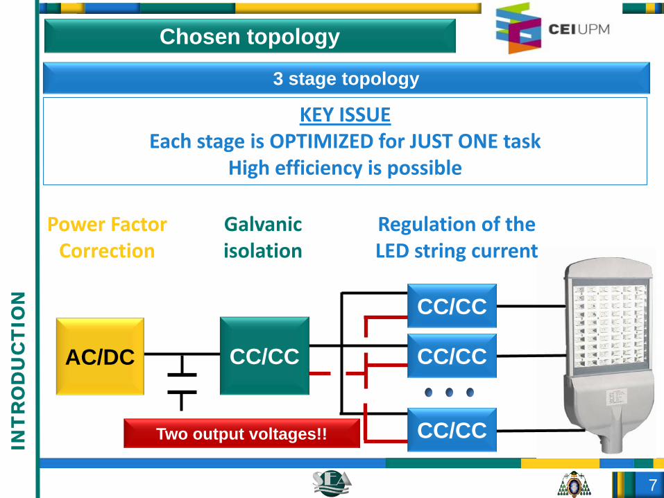
Chosen topology
CC/CC
CC/CC
CC/CC
AC/DC CC/CC
Two output voltages!!
3 stage topology
KEY ISSUEEach stage is OPTIMIZED for JUST ONE task
High efficiency is possible
Regulation of the LED string current
Galvanic isolation
Power Factor Correction
INT
RO
DU
CT
ION

8
First stage
- PFC Boost converter operating at constant frequency without electrolytic capacitors
PFC & Continuous Conduction Mode
SiC Schottky diodes are the solution. The increase in cost is acceptable for AEG POWER SOLUTIONS.
No electrolytic capacitors
Output voltage ripple is high and one of the next stages will have to cancel it…
PROVIDED BY AEG POWER SOLUTIONS
FIR
ST
STA
GE

9
Second stageElectronic transformer Galvanic isolation at very high efficiency but with unregulated outputs (fixed duty cycle)
SE
CO
ND
STA
GE
Vout_2_high
Vout_2_low
npri:nhigh:nhigh
Vout_1=Vin_2
C1
C2
M1
M2
D1_H
D1_L
D2_L
D2_H
npri:nlow:nlow
High efficiency
ZCS in diodes[Secondary leakage inductance-output capacitors] resonance
ZVS in MOSFETs Energy stored in the primary leakage inductance (aided by the magnetizing current)
ZCS implies no output voltage regulating
capabilities, hence…

10
Second stageElectronic transformer Galvanic isolation at very high efficiency but with unregulated outputs (fixed duty cycle)
SE
CO
ND
STA
GE
Vout_2_high
Vout_2_low
npri:nhigh:nhigh
Vout_1=Vin_2
C1
C2
M1
M2
D1_H
D1_L
D2_L
D2_H
npri:nlow:nlow
Unregulated output voltages
Vout_high=Vin · Ghigh
Vout_low=Vin · Glow
Fixed gains
Low-frequency ripple (PFC) needs to be canceled by third
stages

11
Before analyzing the third stages…Vled
Iled
light
V1
V2
I1I2
L1
L2
L=0The design of the third stages should take this into
account
Vdrop
TH
IRD
STA
GE

12
V3_high
V3_low
Vout_3
Vfilter
V 3_high
V 3low
Vfilter
Third stages
Maximum output voltage (D=1) V3_high
Minimum output voltage (D=0) V3_low
Not a real drawback if V3_low is wisely chosen
And the advantages…?
MOSFET and diodes only have to withstand V3_high-V3_low
EFFICIENCY IS CONSIDERABLY HIGHER THAN IN BUCK CONVERTERTH
IRD
STA
GE

13EXPERIMENTAL RESULTS

14
Prototype
Second stage
-200 W-Outputs 140 V & 80 V- ETD 34
Third stages (4x)
-50 W each-E20- Total Current DimmingE
XP
ER
IME
NTA
L R
ES
ULT
S

15
a)
(500 mA/div)
Second stageE
XP
ER
IME
NTA
L R
ES
ULT
S
a)
VGS (10 V/div)
VDS (100 V/div)
ZCS in the diodes of the ET ZVS in the MOSFETs of the ET

16
Third stageE
XP
ER
IME
NTA
L R
ES
ULT
S
a)
VMOSFET (50 V/div)
Vdiode (50 V/div)
Vfilter (25 V/div)
a)
b)
OS (50 /d )
VGS (10 V/div)
Vfilter (25 V/div)
Voltage withstood by MOSFET and diode Input voltage of the filter
140 V 80 V
140 V - 80 V = 60 V
V3_high – V3_low

17
Second + third stageE
XP
ER
IME
NTA
L R
ES
ULT
S
b)a)
Input voltage (100 V/div)
Output current (100 mA/div)
Input voltage (100 V/div)
Output current (100 mA/div)
Constant input voltage in second stage:400 V
Ripple in the input voltage of second
stage: 70 Vpp
c)
/div)
Input voltage (100 V/div)
Output current (100 mA/div)

18
Efficiency of second and third stagesE
XP
ER
IME
NTA
L R
ES
ULT
S
60 80 100 120 14092
93
94
95
η (%)
Pin (W)
Peak efficiency=95.9% at nominal current

19
SUMMARY&
CONCLUSIONS

20
Summary & Conclusions
-A three-stage topology has been developed for LED-based street lighting applications
-Efficiency is high due to the optimization of each stage for just one task
-SiC technology allows us to develop a constant frequency application
-Third stages have been optimized taken into account the special features of the load (i.e.,LEDs) without losing total dimming
CO
NC
LUS
ION
S

21
THANKS!ANY QUESTION?

22
PFC
Two-stage topology
CC/CC
CC/CC
CC/CC
Main features- Low switching losses (BCM)- No electrolytic capacitor
- Variable frequency- Large output-voltage ripple
Main features- Galvanic isolation- Ripple cancelation- Current regulation (dimming)
- N transformers (expensive)

23
Three-stage topology
CC/CC
CC/CC
CC/CC
PFC CC/CC
Main features Main featuresMain features- Low switching losses- No electrolytic capacitor
- Variable frequency- Large output-voltage ripple
- Galvanic isolation- Ripple cancelation
- Variable frequency (typically)
-Current regulation (dimming)
- Reduces efficiency


![[MEAN WELL] 1982 (Charger) DC/AC (Inverter) 8000 (DoE ... · PDF fileAC/DC DC/DC (Converter) (Adaptor) (Charger) DC/AC (Inverter) 8000 LED ... AC AC AC GE12/18/24/30 I AC AC Plug-AU](https://static.fdocuments.us/doc/165x107/5a73363b7f8b9abb538e72a6/mean-well-1982-charger-dcac-inverter-8000-doe-a-acdc-dcdc-converter.jpg)