High-Activity Dealloyed Catalysts - Energy
35
High-Activity Dealloyed Catalysts This presentation does not contain any proprietary, confidential, or otherwise restricted information Anu Kongkanand and Fred Wagner (retired 2012) General Motors Global Product Development, Fuel Cell Activities June 17, 2014 FC087
Transcript of High-Activity Dealloyed Catalysts - Energy

High-Activity Dealloyed Catalysts
This presentation does not contain any proprietary, confidential, or otherwise restricted information
Anu Kongkanand and Fred Wagner (retired 2012)
General Motors Global Product Development, Fuel Cell Activities
June 17, 2014
FC087

• Project start date: 1 Aug 2010 • Project end date: 30 Sep 2014 • Percent complete: 90%
• Barriers addressed – B. Cost
• Decrease required loading of precious metals including platinum
– A. Durability • Maintain kinetic activity, and later high
current density performance, after appropriate accelerated tests
– C. Performance • Achieve and maintain high current
densities at acceptably-high voltages • Total Funding Spent as of 3/31/14: $5.4M
• Total DOE Project Value: $5.95M
• Cost Share: 20%
Timeline
Budget
Barriers
• Subcontractors: – Technical University of Berlin – Johnson Matthey Fuel Cells – Massachusetts Institute of Technology – Northeastern University – George Washington University
• Project lead: GM
Partners
Overview
2

Approach: Basic Concept
PtM3/C -------------> Pt1.5-5M/C precursor dealloying catalyst M is one or
more non-precious metals
e.g., acid leaching, electrochemically dissol’n
Cross section, Pt
in blue
Lattice compression of surface Pt layer
3 From M. Oezaslan, M. Heggen and P. Strasser, J. Am. Chem. Soc. 134 (2012) 514 with permission from ACS
• Erlebacher dealloying of continuous films showed ligament/pore network controlled by relative rates of nonnoble-element dissolution and noble atom surface diffusion tune to improve durability
• Shao-Horn pre-project work suggested high initial non-noble atom concentration generate porous structure
• Strasser pre-project work suggested particle morphology determined by particle size (below)
Question to be answered • Activity-morphology relationship • Desired structure, elements, and
composition for durability • Activity-durability trade-off

– Cost
• Demonstrate reliable oxygen reduction reaction kinetic mass activities > DOE target 0.44 A/mgPGM in H2/O2 fuel cells, using manufacturable synthesis and dealloying procedures
• Achieve high-current-density performance in H2/air fuel cells adequate to meet DOE heat rejection targets and Pt-loading goals of <0.125 gPt/kW and <0.125 mgPt/cm2
geo
– Durability
• Demonstrate durability of the kinetic mass activity against DOE-specified voltage cycling tests in fuel cells
• Determine where alloying-element atoms should reside with respect to the catalyst-particle surface for durable activity
– Performance
• Demonstrate durability of high-current-density performance
• Scale up to full-active-area fuel cells, to be made available for DOE testing
Reduce catalyst cost while achieving the required durable performance, allowing fuel cells to become economically competitive with other power sources.
Relevance
4

Last year AMR
5
catalyst lotNumber of cycles
12/33912/2803000010000030000100000
0.9
0.8
0.7
0.6
0.5
0.4
0.3
0.2
0.1
0.0
MA
(A
/mgP
t), M
EA_1
0.385732
0.502121
0.587374
0.438784
0.566075
0.628678
Mass activities of D-PtNi3 and D-PtCo3
Dealloyed: 1M HNO3, 70C, 24hr
PtNi3 PtCo3
Pt/Ni = 1.8 Pt/Co = 2.2
Milestone 1 initial activity
Milestone 2 after 30k cycles
H2/air, 80°C, 100/100% RHin, stoich 2/2, 170/170kPaabs
EOL target
• Met all DOE 2017 cathode durability of activity target in multiple large-batch catalysts (>100g) for both PtNi and PtCo using several different acid-leaching and thermal annealing treatments.
• Met Milestone 3 (initial high-power performance) but not 4 (durability of high-power performance).
D-PtNi3 vs D-PtCo3 from JM Large-Batch Precursors

Approach: Milestones and Go/No Go
6
JM/GM/MIT
JM/GM/MIT
TUB/MIT/GWU/NEU/JM/GM
TUB/MIT/GWU/NEU/JM/GM
Initial mass activity in MEA
Durability of mass activity
Initial high-power performance
Durability of high-power performance
Task 1
Task 2
Task 3
Task 4
2011 2012 2013
Met Milestones in MEA with Large Batch Materials
Go/No-go Decision
2014
Time Milestone or Go/No-Go Decision Status
May-2012 Milestone 1: Initial ORR mass activity. Satisfied at two labs with large batches catalysts
Oct-2012 Milestone 2: Durability of mass activity. Satisfied at two labs with large batches catalysts
Oct-2012 Go/No-Go: Simultaneously achieve Milestones 1 and 2 with one material
Passed
Dec-2013 Milestone 3: Initial high-current-density performance with Milestone 2-compliant material.
Satisfied at two labs with large batches catalysts
Mar-2014 Milestone 4: Durability of high-current-density performance with Milestone 2-compliant material.
Demonstrated durability in 50cm2 either by (1) using more realistic upper-limit voltage suppression on 0.1mg/cm2 electrode or (2) using DOE 1V cycling test at higher loaded (0.15mg/cm2) electrode. Shortstack test is on-going.

Cycling: 0.6-1.0V 50mV/s, H2/N2, 80
C, 100% RH Cathode loadings: 0.082-0.100 mgPt/cm2 Thermal annealing: 5% H2/N2 at 400
C for 4hrs
PrecursorsDealloying
Post-dealloying AnnealingNumber of cycles
12/28011/176Sulfuric acidNitric acidNitric acid
yesnonono30k10k030k10k030k10k030k10k0
0.80.70.60.50.40.30.20.10.0
Ma
ss A
ctiv
ity
(A
/mg
Pt)
95% CI for the Mean
Initial target
Durability target
Old precursor PtNi3
New precursor PtNi3
Acid leaching
Thermal annealing
Precursor
• Advanced characterization (TEM at MIT, STEM at GM, EXAFS at NEU, and XANES at GWU) were all done on the same MEA sample set generated at GM. (4 types x 3 stages)
Selected MEA-tested Catalysts for Characterization Technical Accomplishment:
7
11/176 12/280
176NA 280SA 280SA-AN280NA
280NA 280SA176NA

11/176-derived catalysts show porous structure and hold less Ni Technical Accomplishment:
8
176NA 280NA
fresh
BOL
30k cyc
Pt
Ni
• 176NA clearly has wider particle-size distribution and retains less Ni when compared with 12/280-derived catalysts.

9
Bulk Ni Content and Activity Technical Accomplishment:
Voltage cycling Voltage cycling
280SA-AN
280SA
176NA
280NA
280SA-AN
176NA
280SA 280NA
Ni/Pt (at.%) Ni/Pt (at.%)
• Ni contents in tested catalysts were measured using EPMA in conjunction with TEM-EDS.
• In most cases (except for 280SA-AN), mass activity decreases with voltage cycling in part due to loss of surface area.
• In contrast to increasing specific activities observed in 12/280-derived catalysts, 176NA lost specific activity.
• Therefore, bulk Ni content provides some indication of ORR activity but there are also other factors.
Mass activity Specific activity

10
BOL Cycled 280SA 1.16±0.57 1.59±0.55
280SA-AN 1.27±0.32 1.62±0.49
Pt-Shell thickness in nm with one st.dev.
Pt Shell Observation Technical Accomplishment:
280SA-EOT
• Pt shell estimation was done using HAADF-STEM and EELS. • Pt shell thicknesses were ~1.2 at BOL and ~1.6nm at 30k cycles.

XAFS Overview Technical Accomplishment:
Purpose of these studies Utilize in situ XAS on operating dealloyed PtM electrocatalysts in order to:
1) identify where the alloying element needs to be in order to impart maximum activity, and
2) how these structures correlate with durability Project achievements 1. Findings regarding PtM dealloyed core-shell particles
a. Effect of second metal: the compression effect is much more important than the ligand effect.
b. Importance of having non-porous Pt shell c. Importance of leaving more Ni in dealloyed catalysts
2. New techniques
a. FEFF calculations from derived structures to determine shifts in the Pt d-band centers
b. Use of ∆µ technique at M-edge to follow Pt skin thickness on Pt-M core-Pt shell nanoparticles
c. Use of ∆µ technique at Pt-edge to confirm Sabatier principle and dual volcano contribution in total activity
11
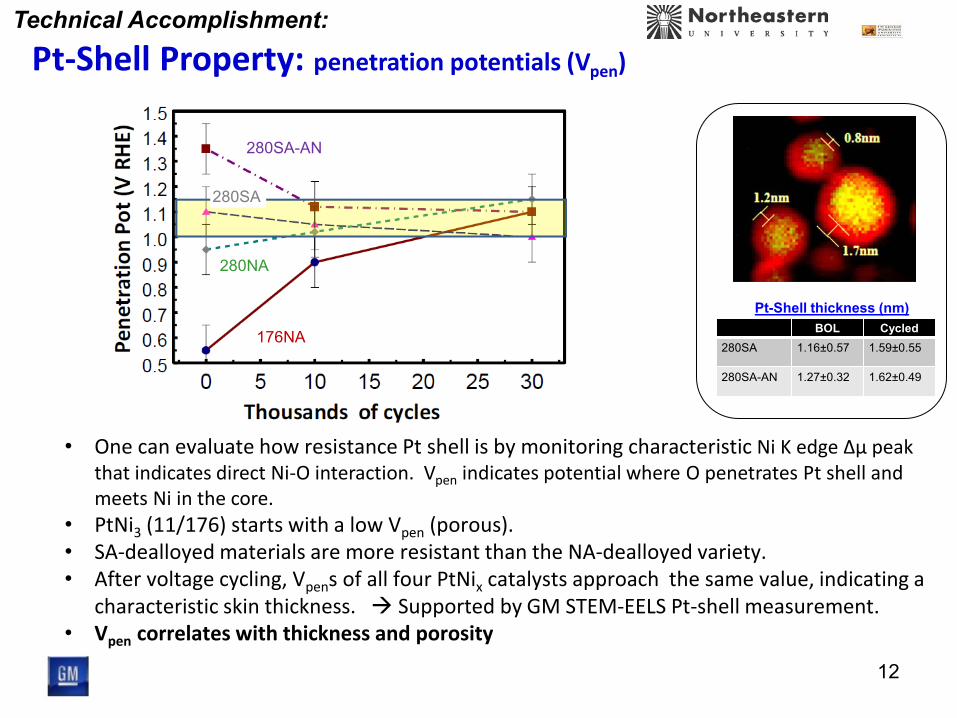
• One can evaluate how resistance Pt shell is by monitoring characteristic Ni K edge Δμ peak that indicates direct Ni-O interaction. Vpen indicates potential where O penetrates Pt shell and meets Ni in the core.
• PtNi3 (11/176) starts with a low Vpen (porous). • SA-dealloyed materials are more resistant than the NA-dealloyed variety. • After voltage cycling, Vpens of all four PtNix catalysts approach the same value, indicating a
characteristic skin thickness. Supported by GM STEM-EELS Pt-shell measurement. • Vpen correlates with thickness and porosity
Pt-Shell Property: penetration potentials (Vpen)
Technical Accomplishment:
12
Pt-Shell thickness (nm) BOL Cycled
280SA 1.16±0.57 1.59±0.55
280SA-AN 1.27±0.32 1.62±0.49
11/176NA
280SA-AN
176NA
280SA
280NA

Pt
Ni
O
Effect of alloying metal: the compression effect is much more important than the ligand effect • Uniform volcano plot vs. Ni/Pt ratio • RPt-Pt (EXAFS) follows the Ni/Pt ratio
Compression, Shell Porosity Technical Accomplishment:
Pt-P
t Coo
rdin
atio
n N
umbe
r
ECSA (m2/gPt)
At the same ECSA, 11/176 shows much smaller Pt-Pt CN than 12/280. This indicates higher porosity for 11/176.
Lower shell porosity = higher activity, durability
pore/defect in shell

Specific activity correlates with OOH surface species in lieu of OH dominating. This points to a relatively lower Pt-O bond strength.
* Ni/Pt ratios from EPMA studies of MEA cathode
Sabatier Principle Confirmation Technical Accomplishment:
12/280 S
peci
fic A
ctiv
ity (m
A/cm
2 )
• To make a durable catalyst, one wants to start from high Ni content.
Specific activities as Ni decreases

Precursor Particle Size / nm 15
Technical Accomplishment: New Catalyst Design: Precursor Size
• Use new synthesis to produce size-selective monodispersed PtNi3 precursors. 3 - 25nm.
• There appeared to be an optimal precursor size for activity.
• Precursor size of 6-8 appeared to be the best in retaining Ni.
Solid core shell
Percolated
Precursor Particle Size / nm

Precursor Composition Technical Accomplishment:
• TUB made precursor with different Pt/Ni composition but all with the same particle size (4nm).
• Found that initial activity increased with Ni content. 16
Pt85Ni15 Pt70Ni30
Pt50Ni50 Pt30Ni70
- Controlling particle size through CO confinement
Cui, et al. JACS 2014, 136, 4813 Cui, et al. Nature Mater. 2013, 12, 765
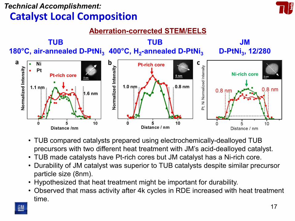
Aberration-corrected STEM/EELS TUB
180°C, air-annealed D-PtNi3
Catalyst Local Composition Technical Accomplishment:
• TUB compared catalysts prepared using electrochemically-dealloyed TUB precursors with two different heat treatment with JM’s acid-dealloyed catalyst.
• TUB made catalysts have Pt-rich cores but JM catalyst has a Ni-rich core. • Durability of JM catalyst was superior to TUB catalysts despite similar precursor
particle size (8nm). • Hypothesized that heat treatment might be important for durability. • Observed that mass activity after 4k cycles in RDE increased with heat treatment
time.
TUB 400°C, H2-annealed D-PtNi3
JM D-PtNi3, 12/280
17

H2/air, 80°C, 60/60% RHin, stoich 2/2, 150/150kPaabs
Pt loading: 0.1 mgPt/cm2
Nafion® NR211 membrane
Local O2 Transport Resistance and Pt Surface Area
• In fact, because the electrodes we’ve developed have low Pt roughness factor (Pt loading
Pt-specific surface area) the ‘local O2 transport resistance’ described by other groups begins to become relevant.
• May require ‘electrode’ development which was out of the original scope of our project. • 0.6-1.0V cycling is more aggressive than that in vehicle operation.
Modeled by Greszler, et al., J. Electrochem. Soc., F831 (2012)
Well-dispersed & High roughness factor
Poorly-dispersed & Low roughness factor
Cartoon from DOE transport proj, Wenbin Gu
Last year AMR
25 m2/gPt
40 m2/gPt
19

Decreasing Upper-Limit Voltage (but longer test) could Enable Dealloyed Catalysts
Technical Accomplishment:
• Reducing upper-limit voltage from 1.0 to 0.925 V (but twice as many cycles) reduced performance decay to an acceptable level. only ~20% losses of surface area and mass activity compared to ~40% losses for the 1V upper limit.
Measurement: H2/air, 80°C, 100/100% RHin, stoich 1.5/2, 170/170kPaabs Cycling: 0.6-1.0V or 0.6-0.925V 50mV/s, H2/N2, 80°C, 100% RH Cathode loadings: 0.086-0.100 mgPt/cm2
Upper-Limit VoltageVoltage-cycling number
1.0000.9253000010000060000200000
0.8
0.7
0.6
0.5
0.4
0.3
Vol
tage
at
1.5A
/cm
2
R.F.= 48 44 38 48 42 29
D-PtNi 12/280
EOT target 0.56V
19

I/C
Voltage-cycling number
1.10
0.95
0.80
6000
020
0000
6000
020
0000
6000
020
0000
0.8
0.7
0.6
0.5
0.4
0.3
Vol
tage
at
1.5A
/cm
2
Electrode Optimization: Ionomer Content Technical Accomplishment:
I/C
Voltage-cycling number
1.10
0.95
0.80
6000
020
0000
6000
020
0000
6000
020
0000
0.8
0.7
0.6
0.5
0.4
0.3
Vol
tage
at
1.5A
/cm
2
R.F.= 46 43 39 48 44 38 47 44 37
EOT target 0.56V
D-PtNi 12/280
• Durability of high-power performance improved with decreasing ionomer-to-carbon ratio.
• The trend was even more obvious in dryer condition. flooding is unlikely. • Similar results were observed in the transport project (2013 AMR) on 0.05 mgPt/cm2
Pt/V electrodes. It was attributed to local oxygen transport resistance.
H2/air, 80°C, 100/100% RHin, stoich 1.5/2, 170/170kPaabs H2/air, 80°C, 32/32% RHin, stoich 1.5/1.8, 150/150kPaabs
Wet Dry
Cycling: 0.6-0.925V 50mV/s, H2/N2, 80°C, 100% RH Cathode loadings: 0.086-0.100 mgPt/cm2
20

Stack Demonstration
Technical Accomplishment:
JM Precursors PtNi3 and PtCo3 (analogous to 12/280)
• Catalyst powder arrived from JM early Feb. These are D-PtNi3 and D-PtCo3 catalysts analogous to 12/280. MEA are being fabricated.
• Built a full-active-area shortstack in Feb. Completed most initial fuel cell performance evaluation.
• Will be tested under DOE-recommended drive-cycle durability protocol.
21
Type Description Pt loading (mgPt/cm2) I/C Cathode ECA
(m²/gPt)
1 GM Pt alloy/CB 0.20 Standard 2 JM 30% PtNi/HSC (14/12) 0.20 Standard 45 3 JM 30% PtNi/HSC (14/12) 0.15 Standard 48 4 JM 30% PtNi/HSC (14/12) 0.10 Standard 45 5 JM 30% PtNi/HSC (14/12) 0.10 High 46 6 JM 30% PtCo/HSC (14/16) 0.10 Standard 49

0.1530.1540.1550.1560.1570.1580.159
0.160.1610.162
JM PtNi,0.20mg/cm2
JM PtNi,0.15mg/cm2
JM PtNi,0.10mg/cm2
JM PtNi,0.10mg/cm2,
Hi I/C
JM PtCo,0.10mg/cm2
Pow
er D
ensit
y, W
/cm
2
Quarter PowerWet
Dry
0.7
0.75
0.8
0.85
0.9
0.95
1
JM PtNi,0.20mg/cm2
JM PtNi,0.15mg/cm2
JM PtNi,0.10mg/cm2
JM PtNi,0.10mg/cm2,
Hi I/C
JM PtCo,0.10mg/cm2
Pow
er D
ensit
y, W
/cm
2
High PowerWet
Dry
Initial Stack Performance Technical Accomplishment:
• Performance of 0.20 mgPt/cm2 PtNi was slightly lower than expected but others performed well.
• PtCo slightly outperformed PtNi at the same loading. • With 0.05 mgPt/cm2 anode, now at 0.16 gPGM/kW. Should get very close to 0.125
gPGM/kW DOE target with lower-loaded anode. • Ionomer distribution in electrode is key to closing gap at dry condition
High Power Quarter Power
23

Catalyst Development for Improved Dispersion Technical Accomplishment:
• To improve dispersion of the catalyst precursor, JM attempted to reduce metal loading and heat treatment temperature.
• Metal loading had smaller impact than heat treatment temperature. • However, at lower-temperature treatment gave incomplete alloying. • JM continues to pursue different synthesis approaches.
23

Manufacturing-friendly Synthesis Technical Accomplishment:
• JM made progress on simplifying their catalyst precursor synthesis process to provide better manufacturability.
• Dealloyed catalyst from this precursor showed similar or better performance than the 12/280 at JM. Will be shipped to GM for validation.
24
± ± ± ± ±

Responses to Last Year AMR Reviewers’ Comments • “does not explore any novel class or type of catalyst” “already known and do not add
new insight into the functional properties of these catalysts” – Because the bulk composition is the same, it does not mean that the catalysts are the same.
The class of catalyst we are working on has only been actively studied in the last several years. We’ve further developed it and demonstrated to be one of the most durable active catalysts in MEA. It is true that many known perspectives were found to apply to this catalyst class in order to make it durable. However, it is highly valuable to be able to prove it so.
• “catalyst lack of consistency in particle size and elemental distribution” “Why not adopt the synthetic path reported by the ANL”
– Our objective is to develop a manufacturable synthesis approach to enable a successful technology transfer from academia to component supplier and then stack integrator. Adopting the ANL synthetic path may facilitate fundamental studies but will deviate from our approach.
• “How the efforts of NEU and GWU were leveraged in the rest of the project is unclear.” – Results reported this year should be a good example for their contributions. Their results have
reinforced our understanding in the structures needed for a durable active catalyst. Those include Pt shell quality/thickness and base-metal composition/location. These newly developed techniques will also be valuable for future catalyst development.
• “Lack of modeling capability to validate demonstrated performance change/durability related to material structure”
– GM has a strong model capability and we place significant values on experimentally-validated model. Yet physical model for low-loaded electrode is still unclear. We will support ANL-led DOE electrode project who will use our catalyst in studying electrode structure-performance correlation.
25

Collaborations (subcontractors) • GM
– Overall project guidance, testing of catalysts, fabrication and testing of MEAs and fuel cells
• Technical University Berlin (TUB) (university)– Prof. Dr. Peter Strasser – née Univ. of Houston (UofH) – Selection of new candidate catalyst systems, pre-fuel-cell evaluation, tie-in to theory
• Johnson Matthey Fuel Cells (JMFC) (industry) – Dr. Rachel O’Malley – Scale-up of synthesis, improved manufacturability of dealloying, incorporation and MEA
testing
• Massachusetts Institute of Technology (MIT) (university) – Prof. Yang Shao-Horn – Electron microscopy, dealloying interpretation, alternate preparations of core/shell structures
• Northeastern University (NEU) (university) – Prof. Sanjeev Mukerjee – X-ray absorption spectroscopy (EXAFS, XANES)
• George Washington University (GWU) (university) -- Prof. David Ramaker – Theoretical support of x-ray absorption spectroscopy, Δμ XANES
Project is working through iterative cycles of synthesis, scaleup, performance evaluation, and characterization
Tech transfer: University Catalyst manufacturer Stack integrator 26

27
Remaining Challenges and Future Work • Demonstration of durability of high-power performance
• Stack testing on-going. Will test any new promising catalysts. (GM/JM)
• Still room to improve high-power performance and its durability – Increasing catalyst surface area, particle size uniformity, and alloy quality are key.
• Alternate PtNi3 syntheses/treatments for improved PSD and high surface area. (JM/TUB) • Fine-tune dealloying and electrode fabrication for improved high-power performance (GM) • Continue development of binary and ternary dealloyed systems (TUB/JM/MIT)
• Effects of base metal leaching on performance is unclear
– Can affect during ink making, electrode fabrication processes, as well as fuel cell performance. • Investigate effect of base metal leaching on performance (ANL project) • Investigate effect of base metal leaching on ink properties (ANL project) • Collaborate with DOE transport team. Fabrication and theory on low-Pt-loaded electrode. (GM)
* Out of the scope of original proposal. Unlikely to be completed * Will continue under ANL-led project

28
Summary • Met all DOE 2017 cathode catalyst targets in multiple large-batch catalysts. • Performed advanced characterization at 5 institutions on the same set of
samples to gain collective learning and ensure consistency. • Developed XAFS techniques to enable characterization of Pt shell and
subsurface metals under fuel cell-relevant environment that can be applied to future catalyst development.
• Catalysts with more Ni generally showed higher ORR activity although not necessary high-power performance.
• Despite similar initial activity, catalysts with better particle-size distribution and smaller particle size retained more Ni, and thus showed better durability of mass activity. This is due to the ability to form more uniform Pt shell over its core.
• Demonstrated that dealloyed catalysts developed under this project might be sufficiently durable if (1) we used higher cathode loading (0.15mgPt/cm2) or if (2) we suppressed the upper-limit voltage to 0.925V with 0.1mgPt/cm2 cathode.
• Successfully transferred and further developed catalyst technology from academia, to catalyst supplier, and to stack integrator in ~3 years.

Acknowledgements
DOE – Dimitrios Papageorgopoulos – Greg Kleen
General Motors – Aida Rodrigues – Amanda Demitrish – Eric Thompson – Jeanette Owejan – Tom Moylan – Joe Ziegelbauer – Ratandeep Singh Kukreja – Nick Irish – Rick Waldo – Vic Liu – Mohammed Atwan – Peter Harvey – Travis Down – Thomas Greszler – Yun Cai – Swami Kumaraguru – Wenbin Gu – Balsu Lakshmanan
National Labs – Erik Farquhar (NSLS X-3B) – Trudy Bolin (APS XOR 9BM)
Johnson Matthey – Rachel O’Malley – Alex Martinez Bonastre – Wayne Turner – Geoff Spikes – Stephen Thorpe – Elvis Christian – Alex Hawkins – Brian Theobald
TU Berlin – Peter Strasser – Stefan Rudi – Chunhua Cui – Lin Gan
MIT – Yang Shao-Horn – Christopher E. Carlton – Binghong Han
Northeastern University – Sanjeev Mukerjee – Qingying Jia
George Washington University – David Ramaker – Keegan Caldwell

30
Technical Back-Up Slides

Sample Overview Technical Accomplishment:
Precursor cycles d(nm) Pt/M Microstructure
PtCo/HSC 100 3-5 2.2 Mostly SC-S
PtCo3/HSC 100 4.0 2.7 50% SC-S, 50% MC-PS
PtNi3/HSC-176
BOL 7.0 8.0 MC-PS w M in PS
10k MC-PS w < M in PS
30k 7.6 19.8 MC-PS w << M in PS
PtNi3/HSC-280
SA-annealed
BOL 5.0 1.8 solid particles
10k
30k 4.7 5.5 solid particles
PtNi3/HSC-280
SA-unannealed
BOL 4.5 2.2 solid particles
10k
30k 5.5 4.9 solid particles
PtNi3/HSC-280
NA-unannealed
BOL 4.7 3.2 solid particles
10k
30k 5.5 9.7 solid particles
(SC) single core
(MC) multiple-core
(S) solid shell
(PS) porous shell
Disordered core
Ordered core
Pt1Co1/C Pt1Co3/C
• Same sample set used in other studies.
• Particle size from MIT TEM. Pt/M from GM EPMA.
NOTES All samples were cycled CCDMs from MEAs except for the (early) PtCox samples which were hand-painted electrodes on carbon cloth.

• Direct M-O interaction is only possible when O(H) has penetrated the Pt surface. • This is easily followed, by monitoring the amplitude of the initial Ni K edge Δμ
peak. • Potential where O(H) can penetrate Pt surface (Vpen) illustrates Pt shell property.
0.2 0.3 0.4 0.5 0.6 0.7 0.8 0.9 1.0 1.1 1.2
-0.04
-0.03
-0.02
-0.01
0.00
0.01
0.02
0.03
N2 O2BOL10K30K
LigandDirect
Potential (V RHE)
|∆µ|
at (
-5-0
) eV
PtNi3∆µmax Vpen
11/176NA
Direct and indirect Ni-O interaction Technical Accomplishment:
32
Pt
Ni

How Close is Ni to the Surface? Δμ at the Ni K edge Technical Accomplishment:
• Indirect Co-O (or Ni-O) interactions, a marker for adsorbates coming on the outer edge of the Pt skin, as seen by M atoms in the direct subsurface layer.
• Give opportunity, for first time, to observe immediate subsurface M under potential control
TOP: Pt4Co2-(O) clusters used for the FEFF8 calculations MIDDLE: Experimental Co K edge Δμ data for dealloyed Pt1Co1/C at the indicated potentials BOTTOM: FEFF8 calculated Δμ signals from the above models. Note that the amplitude of the first peak (positive or negative) serves as a marker for direct or indirect Co-O interactions
Pt
Co or Ni
O

-10 0 10 20 30 40 50-0.01
0.00
0.01
0.02
0.03
O54biO70biO90biO100biN100biN90biN70bi
Theory (FEFF8)
2nd O OO OH O
N2 0.90 OH* 1.15 O*
O2 0.54 0.74
O2 0.90 OH* 1.00 O*+OH*
∆ µ
OPt
Energy (eV rel. Pt L3 edge)
OPt
HO
OOH*
2.4 2.2 2.1
HOPt
OPt
HO H
HOOH*
∆µ = µ(V, O2 or N2 sparged) - µ(0.54, N2 sparged) for catalyst SAu (BOL) at the indicated potentials. Also indicated are FEFF8 results for the indicated adsorbates with Pt-O bond lengths as indicated in Å producing the shifts of the 30-45 eV peak. The contribution from the second O in the OOH* is highlighted in red, that from the H in the OH in blue, as determined from the difference in ∆µ with and without the second atom. The H “outside” the second O in OOH is not included in the FEFF8 calculations.
Dealloyed PtNi3 (12/280), SA unannealed
Absorbate chemistries and geometries serve as markers of Pt-O bond strength, and are correlated well with theory (Norskov, Adzic, etc.)
Identify Oxygen Species with Δμ at the Pt L3 edge Technical Accomplishment:

Our observations on real-life, operating nanoparticles correlate with literature on “ideal” surfaces measured by RDE.
XAFS Final Observations Technical Accomplishment:
Our results overlaid on
Markovic 2013 AMR
These results should serve as a roadmap for the rational design of new catalysts.