High-Accuracy AM-FM Radar with an Active Reflector
9
Research Article High-Accuracy AM-FM Radar with an Active Reflector Mun Gak Choi, 1 Dong Sik Woo, 2 Hyun Chul Choi, 1 and Kang Wook Kim 1 1 School of Electronics Engineering, Kyungpook National University, 80 Daehak-ro, Buk-gu, Daegu 41566, Republic of Korea 2 Department of Aviation Information and Communications Engineering (KAI-TECH), Kyungwoon University, 730 Gangdong-ro, Sandong-myun, Gumi 39610, Republic of Korea Correspondence should be addressed to Kang Wook Kim; kang [email protected] Received 3 August 2016; Revised 27 November 2016; Accepted 9 January 2017; Published 30 January 2017 Academic Editor: Eduard Llobet Copyright © 2017 Mun Gak Choi et al. is is an open access article distributed under the Creative Commons Attribution License, which permits unrestricted use, distribution, and reproduction in any medium, provided the original work is properly cited. An amplitude-modulated and frequency-modulated (AM-FM) radar with an active reflector to produce high-accuracy distance measurements is proposed and demonstrated in this paper. e proposed radar consists of an AM-FM base module and an active reflector. e combination of AM and FM modulations resolves ambiguity of the absolute distance in typical AM radars, while improving range accuracy in typical FM radars with narrow bandwidth. Also, the active reflector, which translates the frequency of the received signal, resolves the problem of phase detection interference due to the direct Tx-to-Rx leakage in AM radars. In this paper, the operating principle, experimental tests, and analysis are presented. e implemented AM-FM radar operates in X-band (Tx: 10.5 GHz, Rx: 8.5 GHz) with the 620 MHz bandwidth. e measured range accuracy of less than ±10 mm at a distance of 70 m is obtained. 1. Introduction Accurate noncontact distance measurement systems are widely used in various applications. Position measurement methods can be divided into different categories depending on the utilized technologies such as ultrasound, GPS, laser, and RF/microwave waves [1]. Attempts to use optical fibers for the detection of cracks and vibrations in bridges or tunnels have also been reported [2]. ese distance measurement technologies have their own advantages and disadvantages. An ultrasonic system is lim- ited to short-range distances in a small area because of its low precisions; it is widely employed in rear bumper proximity sensors of commercial vehicles. e accuracy of typical GPS- based distance measuring systems is approximately 10 m, and, therefore, it is not suitable for the detection of structural faults. Laser sensors have a range of up to several hundred meters and mm-level accuracy. However, their performance degrades rapidly under the influence of heavy raining or foggy weather and with lens or reflector contamination. An alignment of the laser beam is also required for accurate mea- surements. On the other hand, a radar-based sensor, using electromagnetic radiation, can operate reliably under harsh weather conditions. erefore, the radar technology is widely used not only in military systems but also in a number of industrial applications such as automotive radars, blind spot monitoring, and level gauges. Active researches have been performed for the high-resolution radar technology with the mm-level accuracy [3–9]. Both ultrawideband (UWB) [3–7] and wideband frequency-modulated continuous-wave (FMCW) [8, 9] techniques were used to achieve this level of precision. In this paper, we propose a practical ranging system with mm-accuracy using AM-FM radar combined with the active reflectors. e frequency translating active reflector is utilized in order to significantly reduce the phase detection ambiguity in AM radars related to interference or multipath signal reception. e proposed AM-FM radar uses narrower bandwidth as compared with other methods. 2. AM-FM Radar and the Active Reflector 2.1. Overview of the Proposed AM-FM Radar. e proposed AM-FM radar module combines amplitude modulation (AM) and frequency modulation (FM) based radars with an active reflector. A simplified block diagram of the proposed system is shown in Figure 1. e proposed system consists Hindawi Journal of Sensors Volume 2017, Article ID 8589469, 8 pages https://doi.org/10.1155/2017/8589469
Transcript of High-Accuracy AM-FM Radar with an Active Reflector
Research ArticleHigh-Accuracy AM-FM Radar with an Active Reflector
Mun Gak Choi,1 Dong Sik Woo,2 Hyun Chul Choi,1 and Kang Wook Kim1
1School of Electronics Engineering, Kyungpook National University, 80 Daehak-ro, Buk-gu, Daegu 41566, Republic of Korea2Department of Aviation Information and Communications Engineering (KAI-TECH), Kyungwoon University,730 Gangdong-ro, Sandong-myun, Gumi 39610, Republic of Korea
Correspondence should be addressed to Kang Wook Kim; kang [email protected]
Received 3 August 2016; Revised 27 November 2016; Accepted 9 January 2017; Published 30 January 2017
Academic Editor: Eduard Llobet
Copyright © 2017 Mun Gak Choi et al.This is an open access article distributed under the Creative Commons Attribution License,which permits unrestricted use, distribution, and reproduction in any medium, provided the original work is properly cited.
An amplitude-modulated and frequency-modulated (AM-FM) radar with an active reflector to produce high-accuracy distancemeasurements is proposed and demonstrated in this paper. The proposed radar consists of an AM-FM base module and an activereflector. The combination of AM and FM modulations resolves ambiguity of the absolute distance in typical AM radars, whileimproving range accuracy in typical FM radars with narrow bandwidth. Also, the active reflector, which translates the frequencyof the received signal, resolves the problem of phase detection interference due to the direct Tx-to-Rx leakage in AM radars. In thispaper, the operating principle, experimental tests, and analysis are presented. The implemented AM-FM radar operates in X-band(Tx: 10.5 GHz, Rx: 8.5 GHz) with the 620MHz bandwidth. The measured range accuracy of less than ±10mm at a distance of 70mis obtained.
1. Introduction
Accurate noncontact distance measurement systems arewidely used in various applications. Position measurementmethods can be divided into different categories dependingon the utilized technologies such as ultrasound, GPS, laser,and RF/microwave waves [1]. Attempts to use optical fibersfor the detection of cracks and vibrations in bridges or tunnelshave also been reported [2].
These distancemeasurement technologies have their ownadvantages and disadvantages. An ultrasonic system is lim-ited to short-range distances in a small area because of its lowprecisions; it is widely employed in rear bumper proximitysensors of commercial vehicles. The accuracy of typical GPS-based distancemeasuring systems is approximately 10m, and,therefore, it is not suitable for the detection of structuralfaults. Laser sensors have a range of up to several hundredmeters and mm-level accuracy. However, their performancedegrades rapidly under the influence of heavy raining orfoggy weather and with lens or reflector contamination. Analignment of the laser beam is also required for accuratemea-surements. On the other hand, a radar-based sensor, usingelectromagnetic radiation, can operate reliably under harshweather conditions.Therefore, the radar technology is widely
used not only in military systems but also in a number ofindustrial applications such as automotive radars, blind spotmonitoring, and level gauges. Active researches have beenperformed for the high-resolution radar technology withthe mm-level accuracy [3–9]. Both ultrawideband (UWB)[3–7] and wideband frequency-modulated continuous-wave(FMCW) [8, 9] techniques were used to achieve this level ofprecision.
In this paper, we propose a practical ranging systemwith mm-accuracy using AM-FM radar combined with theactive reflectors. The frequency translating active reflector isutilized in order to significantly reduce the phase detectionambiguity in AM radars related to interference or multipathsignal reception. The proposed AM-FM radar uses narrowerbandwidth as compared with other methods.
2. AM-FM Radar and the Active Reflector
2.1. Overview of the Proposed AM-FM Radar. The proposedAM-FM radar module combines amplitude modulation(AM) and frequency modulation (FM) based radars with anactive reflector. A simplified block diagram of the proposedsystem is shown in Figure 1. The proposed system consists
HindawiJournal of SensorsVolume 2017, Article ID 8589469, 8 pageshttps://doi.org/10.1155/2017/8589469

2 Journal of Sensors
AM-FM radar(base module, BM)
Active reflector(tag module, TM)
Amplitudemod.
STALO
AMdemod.
Phasedetector
OCXO
R
TX
RX
RX
TX
STALO
Frequencymod.
Beatfrequency
19GHz
f1
f2
100MHz
10.5GHz
Δ𝜙
fbeat
Figure 1: Simplified block diagram of the proposed AM-FM radar.
of two parts: an AM-FM radar module (base module, BM)and an active reflector module (tag module, TM). In theAM-FM radar base module, a CW microwave signal is firstfrequency-modulated and then amplitude-modulated. TheAM-FM signal is transmitted toward the active reflector.The active reflector at the target location receives the AM-FM signal, translates the center frequency of the signal, andretransmits the signal with amplification. Then, the baseradar module receives the retransmitted signal from TM anddetermines the absolute distance with combination of thebeat frequency due to FM modulation and phase delay dueto AM modulation. The beat signal due to FM modulationhelps to obtain the rough absolute distance on the order of1m. The phase delay due to AM modulation helps to resolvethe distance with mm-accuracy. The ambiguity of absolutedistance in AM radars is overcome with the combinationof the FM modulation. Also, with an active reflector, whichtranslates frequency of the received signal and retransmitsit toward the base system, the phase detection interferenceproblem in typical AM radars can be resolved.
In the next paragraphs, FMCW and amplitude-modula-ted continuous-wave (AMCW) radar principles are brieflysummarized, and the benefits of adapting active reflectors aredescribed.
2.2. FMCW Radar. A typical bistatic and homodyne FMCWradar configuration [10, 11] is adapted for the proposed AM-FM radar system. In general radar system, range accuracy isa concept that should be distinguished from range resolutionbut is related to it. The range resolution (𝛿𝑅) and bandwidth(𝐵) relation is
𝛿𝑅 =𝑐
2𝐵, (1)
where 𝑐 is speed of light. High range resolution increasesrange accuracy [12]. Therefore, to achieve high accuracy inradar system, wide bandwidth is essentially needed.
On the other hand, another limitation is present due tothe signal processing. Typically, in order to acquire the beatfrequency of the received signal, an analog beat signal is firstsampled using an analog-to-digital converter, and then thefast Fourier transform (FFT) algorithm is utilized. As theresult of FFT, the beat frequency is discretely distributed.Themaximum beat frequency error equals the FFT step size, andthe differences exist between the real beat frequency and thediscrete beat frequency by FFT [13]. The FFT step size (Δ𝑓)can be calculated as follows:
Δ𝑓 =𝑓𝑠𝑁𝑠, (2)
where𝑓𝑠 is the sampling frequency and𝑁𝑠 is the total numberof data samples during the sampling period. Thus, the rangestep size (Δ𝑅FFTmax) according to the FFT step size is as follows:
Δ𝑅FFTmax =𝑐𝑇Δ𝑓
2𝐵=𝑐𝑇
2𝐵⋅𝑓𝑠𝑁𝑠, (3)
where 𝑇 is chirp period. As shown in (1) and (3), high rangeaccuracy requires both wide frequency bandwidth and high-performance hardware.
2.3. AMCW Radar. The AMCW radar system was reportedin [14], and certain drawbacks of the AMCW radar werepointed out. First, the maximum measurable distance, with-out ambiguity, is limited to the wavelength of the modulationfrequency. Second, the leakage power between transmitter(Tx) and receiver (Rx) antennas induces the phase detectionerror. In spite of these problems, the AMCW radar hasseveral advantages: (1) a very simple structure and (2) highrange accuracy achievable by an increase in the modulationfrequency. Consequently, the AMCW method was used insome special applications such as a short-range radar andplasma diagnostics [15].

Journal of Sensors 3
Beat frequency
1 2 3 4 50Frequency (MHz)
−100
−80
−60
−40
−20
0
(dBm)fbeat
(a) FFT result of the beat signal
Time (ns)
−1.5
−1
−0.5
0
0.5
1
1.5Ref. and demodulated signals
2055
9
2055
7
2055
5
2055
3
2055
1
2054
9
2054
7
2054
5
2054
3
2054
1
2053
9
Ref.DeMod.
Δ𝜙m
(b) Phase difference
Figure 2: Typical cases of beat frequency and phase difference.
Table 1: Range errors in the AMCW radar with no leakages.
Phase detectionerror 𝑓𝑚 = 10MHz 𝑓𝑚 = 50MHz 𝑓𝑚 = 100MHz
1∘ 41.67mm 8.33mm 4.17mm5∘ 208.33mm 41.67mm 20.83mm10∘ 416.67mm 83.33mm 41.67mm
The transmitted signal of the AMCW radar is amplitude-modulated, consisting of the carrier (𝑓𝑐) and double side-bands (𝑓𝑐 ± 𝑓𝑚) in the frequency domain. The distance 𝑅AMbetween the radar and the target is
𝑅AM =𝑐 ⋅ Δ𝜙𝑚4𝜋𝑓𝑚, (4)
where Δ𝜙𝑚 is the phase difference between the reference andthe received signals and 𝑓𝑚 is the modulation frequency.Table 1 summarizes the range errors corresponding to thedifferent phase detection errors and 𝑓𝑚. Here, the ambiguityof absolute distance exists depending on the modulationfrequency. Distance ambiguity of AM radar with 100MHzmodulation frequency is 1.5m.
In a typical AMCW radar, a portion of the transmittedsignal is routed to the received signal path through Tx/Rxantennas or isolators. The major factor causing an error inthe AMCW radar is the ratio of the main echo signal andthe direct Tx-to-Rx leakage signal. For ±1∘ phase accuracy,the echo signal should be at least 12 dB stronger than thedirect leakage signal. However, the direct leakage power iskept constant, while the echo signal decreases as the distance𝑅 increases. In the proposed AM-RM radar, a frequency-shifting active reflector removes the problem of the direct Tx-to-Rx signal leakage.
2 4 60R (m)
0
2
4
6R
calc
. (m
)
RAMFMRAMRFM
Figure 3: Distance estimation of AMCW (red), FMCW (blue), andcombination of AM-FM (black) radar.
2.4. Combined AM-FM Radar. The absolute distance bet-ween the AM-FM radar base module and the active reflector(𝑅AMFM) can be calculated as follows:
𝑅AMFM = 𝑅AM + 𝑅FM =𝑐 ⋅ Δ𝜙𝑚4𝜋𝑓𝑚+𝑐𝑇𝑓beat FFT2𝐵, (5)
where 𝑅AM is the range due to Δ𝜙𝑚 of the AMCW radarand 𝑅FM is the range due to the FFT result of beat frequency(𝑓beat FFT) of the FMCW radar. 𝑅FM is discrete due to the FFTstep size, but 𝑅AM varies continuously within unambiguousregion. Figure 2 presents typical cases of 𝑓beat FFT and Δ𝜙𝑚.The absolute distance estimation by combining the FM andAM distance measurements using (5) is shown graphicallyin Figure 3. As a result, high-accuracy distance measurementcan be achieved.

4 Journal of Sensors
2.5. Active Reflector. An active reflector is typically used inthe radar system for calibration. The active radar calibrator(ARC) is composed of two antennas (sending and receiving)and an RF amplifier. Despite its small size, it is possible toobtain a high standard radar cross section (RCS) value inthe radar system [16]. In the proposed AM-FM radar system,the active reflector translates the frequency of the incomingsignal and retransmits it toward the radar base module.Adopting the active reflector has two advantages. First, theproblem of the direct Tx-to-Rx leakage through antennas orisolators can be solved due to frequency translation, removingthe serious drawback of the AMCW radar system. Second,a high conversion gain can be achieved by splitting the gainbetween the base module and the active reflector module.
3. Implementation and Measurement Results
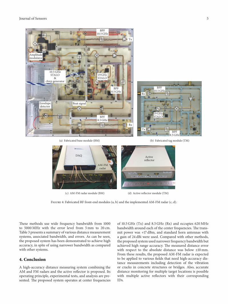
3.1. Design and Implementation. TheproposedAM-FM radarconsists of two parts as presented in Figure 1. One is thebase module (BM, AM-FM radar) and the other is thetag module (TM, active reflector). In the BM, a 100MHzOCXO provides the reference signal for the phase detector,as well as the baseband signal of the amplitude modulation.The OCXO is also used as a reference of the PLL in the10.5 GHz stable local oscillator (STALO) and as a systemclock for the direct digital synthesizer (DDS), providing thelinear frequency modulation. An amplitude-modulated andfrequency-modulated 10.5 GHz signal is transmitted throughthe Tx antenna of the BM and is received by the Rx antennaof the TM at the target location. The TM converts the centerfrequency of the received signal from 10.5GHz to 8.5GHzwith the help of 19GHz STALO and retransmits the filteredand amplified signal using the Tx of the TM. Then, the BMreceives the 8.5GHz AM-FM signal and demodulates it intothe phase delayed signal which is produced by the envelopedetector and also into the beat signal with the help of thefrequencymixer.The combination of the phase difference andthe beat frequency enables calculating the absolute distanceof the target with high accuracy. The overall gain budget iscalculated using a spreadsheet and verified with the systemsimulator, NI AWRMicrowave Office (MWO).
Figure 4 shows the fabricated RF front-end modules ofthe AM-FM radar. For the RF circuit, 20mil thick RO4003(𝜀𝑟 = 3.38; tan 𝛿 = 0.0027) substrate is used. Passivecomponents such as the filter, power divider, and powerdetector were simulated using the 2.5D EM simulator of theNI AWRMWO. RF PCBs are mounted in a metal housing inseparate channels. Regulators for the bias and other circuitsare mounted on the bottom side of the housing.
The transmit power of the BM is +17.6 dBm.The FMchirpsignal is generated using the DDS. With the FM bandwidthof 420MHz, the chirp period of 200𝜇s is achieved for bothrising and falling. The AM signal is generated using theRF mixer and the combiner. The modulation index is 20%.Total RF bandwidth results in 620MHz. The Tx spectrumof the BM is shown in Figure 5(a), and the down-convertedspectrum of the TM is shown in Figure 5(b). The IQ-mixerand NI DAQ are used for the phase calculation, while the
Table 2: Proposed AM-FM radar specifications.
Parameters Unit ValueBase moduleTx power dBm 17.6Tx frequency GHz 10.5Rx frequency GHz 8.5AMmodulation index % 20AM conversion gain dB 3.5FM bandwidth MHz 420FM sweep frequency kHz 2.5FM conversion gain dB 61.5
Tag moduleRx frequency GHz 8.5Tx frequency GHz 10.5Conversion gain dB 32
Antenna (horn)Gain dBi 24Beam width ∘ 20
beat frequency is measured with the aid of the NI-SCOPE.Detailed system specifications are summarized in Table 2.
3.2. Measurements. To verify performance of the proposedsystem, outdoor experiments were carried out at a Universityparking lot. The measurement setup is presented in Figure 6.The distance between the BM and the TM was varied from71m to 73m. The phase difference and the beat frequencywere measured at 10 cm intervals. For fine measurements,distance intervals of 5 cm and 1 cm were used.
The measured phase difference and beat frequency areplotted in Figure 7(a). A commercial data acquisitionmodule(NI USB-5133) and its FFT function software were used toanalyze the FM data. With 10MHz of 𝑓𝑠 and number ofsamples of 1024, the FFT step size was 9.766 kHz. In theproposed system, the FM bandwidth is 420MHz, and thesweep frequency is 2.5 kHz. The distance of phase ambiguityin the AM radar (100MHz) is 1.5m, and the correspondingFFT step for 1.5m distance is 21 kHz. Therefore, there are ∼2beat frequency hops within a phase change of 2𝜋 in the AMmeasurement.Themeasured beat frequency of the FM signalis divided by 21 kHz and a truncated integer bin number isobtained to calculate the base distance estimated by the FMmeasurement (i.e., (bin number) × 1.5m). Then, the distancecalculated from the phase delay of the AMmodulation signalis added to obtain the absolute distance using (5) as shown inFigure 7(b).
A zoomed portion of the fine-measured data in Fig-ure 7(b) is plotted in Figure 7(c) with the calculated error.From the figure, the precision of the tested system is estimatedas ±10mm.
3.3. Discussion. Competing technologies for the high-ac-curacy distance measurements include FMCW and UWB.
Journal of Sensors 5
Tx
Rx
Envelopedetector
STALO&
chirp generatorSTALO
BPF
BPF
Amplitudemodulator
Beat signal
19GHz10.5GHz
10.5GHz
8.5GHz
BPF8.5GHz
(a) Fabricated base module (BM)
Tx
Rx
STALO
BPF
BPF
19GHz
10.5GHz
8.5GHz
(b) Fabricated tag module (TM)
DAQ
I Q I_ Q_ temp temp
AM-FMradar
fbeat Pout
(c) AM-FM radar module (BM)
Activereflector
(d) Active reflector module (TM)
Figure 4: Fabricated RF front-end modules (a, b) and the implemented AM-FM radar (c, d).
These methods use wide frequency bandwidth from 1000to 5000MHz with the error level from 5mm to 20 cm.Table 3 presents a summary of various distance measurementsystems, associated bandwidth, and errors. As can be seen,the proposed system has been demonstrated to achieve highaccuracy, in spite of using narrower bandwidth as comparedwith other systems.
4. Conclusion
A high-accuracy distance measuring system combining theAM and FM radars and the active reflector is proposed. Itsoperating principle, experimental tests, and analysis are pre-sented. The proposed system operates at center frequencies
of 10.5 GHz (Tx) and 8.5GHz (Rx) and occupies 620MHzbandwidth around each of the center frequencies. The trans-mit power was +17 dBm, and standard horn antennas witha gain of 24 dBi were used. Compared with other methods,the proposed systemused narrower frequency bandwidth butachieved high range accuracy. The measured distance errorwith respect to the absolute distance was below ±10mm.From these results, the proposed AM-FM radar is expectedto be applied to various fields that need high-accuracy dis-tance measurements including detection of the vibrationor cracks in concrete structures or bridges. Also, accuratedistance monitoring for multiple target locations is possiblewith multiple active reflectors with their correspondingIDs.

6 Journal of Sensors
FMAM
FM BW: 420MHz
AM BW: 100MHz
Total BW: 620MHz
20dBc
(a) Tx spectrum of the base module (BM)
TMBM
8.5GHz 10.5GHz
(b) Frequency converted spectrum of the tag module (TM)
Figure 5: Frequency spectra of the fabricated system.
Base module
Tag module
Horn antennaPC
DAQ & scope
R: 71m
(a) Base module
Tag module
Horn antenna
Laser pointer
Rail: 2m
(b) Tag module
fbeat
(c) NI-SCOPE GUI for 𝑓beat
Δ𝜙m
(d) LabVIEW program for Δ𝜙𝑚
Figure 6: Outdoor measurement setup.

Journal of Sensors 7
Phase
7150 7200 7250 7300 73507100TM position (cm)
1.07
1.08
1.09
1.10
1.11
−200
−150
−100
−50
050100150200
Phas
e (de
g)
fbeat
fbe
at(M
Hz)
(a) Measured beat frequency (𝑓𝑏) and phase delay (Δ𝜙)
R (c
m)
calc
ulat
ed
R (c
m)
com
pens
ated
7650
7700
7750
7800
7850
7900
7150 7200 7250 7300 73507100TM position (cm)
7100
7150
7200
7250
7300
7350
(b) Calculated distance (𝑅) using 𝑓𝑏 and Δ𝜙
R (c
m)
com
pens
ated
Calc RIdeal
±10mm
7300
7305
7310
7315
7320
7325
7330
7335
7340
7305 7310 7315 7320 7325 7330 7335 73407300TM position (cm)
−4
−2
0
2
4
Erro
r (cm
)
(c) Zoomed up portion of Figure 7(b) and the distance error
Figure 7: Measurement results of proposed system in outdoor fields.
Table 3: Comparison of high-accuracy radar systems.
System architecture Center frequency Bandwidth Error Operating rangeThis work AM-FM 10.5/8.5 GHz 620MHz 10mm 70m[3] UWB 5.4∼10.6GHz 5200MHz 5mm 5m[4] UWB 7∼8GHz 1000MHz 1.7 cm 10m[5] UWB 3.7∼5GHz 1300MHz 20 cm 8m[6] UWB 3.2∼5.2GHz 2000MHz 1 cm 8m[7] UWB 0.01∼5GHz 4990MHz 1.5 cm 2m[8] FMCW 5.8GHz — 10 cm 40m[9] FMCW 5.8GHz 150MHz 18 cm 40m
Competing Interests
The authors declare that they have no competing interests.
Acknowledgments
This research was supported by the National R&D Programthrough the National Research Foundation of Korea (NRF)funded by the Ministry of Education, Science, and Technol-ogy (NRF-2015M1A7A1A02002291).
References
[1] S. Tokoro, “Automotive application systems of a millimeter-wave radar,” in Proceedings of the IEEE Intelligent VehiclesSymposium, pp. 260–265, Tokyo, Japan, September 1996.
[2] T. Bao, J. Wang, and Y. Yao, “A fiber optic sensor for detectingand monitoring cracks in concrete structures,” Science ChinaTechnological Sciences, vol. 53, no. 11, pp. 3045–3050, 2010.
[3] C. Zhang, M. J. Kuhn, B. C. Merkl, A. E. Fathy, and M. R.Mahfouz, “Real-time noncoherent UWB positioning radar

8 Journal of Sensors
with millimeter range accuracy: theory and experiment,” IEEETransactions on Microwave Theory and Techniques, vol. 58, no.1, pp. 9–20, 2010.
[4] B. Waldmann, R. Weigel, and P. Gulden, “Method for highprecision local positioning radar using an ultra widebandtechnique,” in Proceedings of the IEEE MTT-S InternationalMicrowave Symposium Digest (MTT ’08), pp. 117–120, IEEE,Atlanta, Ga, USA, June 2008.
[5] A. Fujii, H. Sekiguchi, M. Asai, S. Kurashima, H. Ochiai,and R. Kohno, “Impulse radio UWB positioning system,” inProceedings of the IEEE Radio and Wireless Symposium (RWS’07), pp. 55–58, Long Beach, Calif, USA, January 2007.
[6] Z. N. Low, J. H. Cheong, C. L. Law, W. T. Ng, and Y. J.Lee, “Pulse detection algorithm for line-of-sight (LOS) UWBranging applications,” IEEE Antennas and Wireless PropagationLetters, vol. 4, no. 1, pp. 63–67, 2005.
[7] R. Zetik, J. Sachs, and R. Thoma, “UWB localization—activeand passive approach,” in Proceedings of the 21st IEEE Instru-mentation andMeasurement TechnologyConference (IMTC ’04),vol. 2, pp. 1005–1009, May 2004.
[8] A. Stelzer, K. Pourvoyeur, andA. Fischer, “Concept and applica-tion of LPM—a novel 3-D local position measurement system,”IEEE Transactions onMicrowaveTheory and Techniques, vol. 52,no. 12, pp. 2664–2669, 2004.
[9] F. Ellinger, R. Eickhoff, R. Gierlich et al., “Local positioning forwireless sensor networks,” in Proceedings of the IEEE GlobecomWorkshops, pp. 1–6, Washington, DC, USA, November 2007.
[10] G. M. Brooker, “Understanding millimetre wave FMCWradars,” in Proceedings of the 1st International Conference onSensing Technology, pp. 152–157, IEEE, Palmerston North, NewZealand, November 2005.
[11] B. R. Mahafza, Radar Systems Analysis and Design UsingMATLAB, Chapman and Hall/CRC, Boca Raton, Fla, USA,2000.
[12] G. R. Curry, Radar System Performance Modeling, ArtechHouse, 2nd edition, 2004.
[13] E. Hyun and J. H. Lee, “Method to improve range and velocityerror using de-interleaving and frequency interpolation forautomotive FMCW radars,” International Journal of SignalProcessing, Image Processing and Pattern Recognition, vol. 2, no.2, 2009.
[14] O.K.Nilsen andW.D. Boyer, “AmplitudemodulatedCWradar,”IRE Transactions on Aerospace andNavigational Electronics, vol.9, no. 4, pp. 250–254, 1962.
[15] C. Laviron, A. J. H. Donne, M. E. Manso, and J. Sanchez,“Reflectometry techniques for density profile measurements onfusion plasmas,” Plasma Physics and Controlled Fusion, vol. 38,no. 7, pp. 905–936, 1996.
[16] D. R. Brunfeldt and F. T. Ulaby, “Active reflector for radar cali-bration,” IEEE Transactions on Geoscience and Remote Sensing,vol. 22, no. 2, pp. 165–169, 1984.

International Journal of
AerospaceEngineeringHindawi Publishing Corporationhttp://www.hindawi.com Volume 2014
RoboticsJournal of
Hindawi Publishing Corporationhttp://www.hindawi.com Volume 2014
Hindawi Publishing Corporationhttp://www.hindawi.com Volume 2014
Active and Passive Electronic Components
Control Scienceand Engineering
Journal of
Hindawi Publishing Corporationhttp://www.hindawi.com Volume 2014
International Journal of
RotatingMachinery
Hindawi Publishing Corporationhttp://www.hindawi.com Volume 2014
Hindawi Publishing Corporation http://www.hindawi.com
Journal ofEngineeringVolume 2014
Submit your manuscripts athttps://www.hindawi.com
VLSI Design
Hindawi Publishing Corporationhttp://www.hindawi.com Volume 2014
Hindawi Publishing Corporationhttp://www.hindawi.com Volume 2014
Shock and Vibration
Hindawi Publishing Corporationhttp://www.hindawi.com Volume 2014
Civil EngineeringAdvances in
Acoustics and VibrationAdvances in
Hindawi Publishing Corporationhttp://www.hindawi.com Volume 2014
Hindawi Publishing Corporationhttp://www.hindawi.com Volume 2014
Electrical and Computer Engineering
Journal of
Advances inOptoElectronics
Hindawi Publishing Corporation http://www.hindawi.com
Volume 2014
The Scientific World JournalHindawi Publishing Corporation http://www.hindawi.com Volume 2014
SensorsJournal of
Hindawi Publishing Corporationhttp://www.hindawi.com Volume 2014
Modelling & Simulation in EngineeringHindawi Publishing Corporation http://www.hindawi.com Volume 2014
Hindawi Publishing Corporationhttp://www.hindawi.com Volume 2014
Chemical EngineeringInternational Journal of Antennas and
Propagation
International Journal of
Hindawi Publishing Corporationhttp://www.hindawi.com Volume 2014
Hindawi Publishing Corporationhttp://www.hindawi.com Volume 2014
Navigation and Observation
International Journal of
Hindawi Publishing Corporationhttp://www.hindawi.com Volume 2014
DistributedSensor Networks
International Journal of