Hierarchical Component Models - A True...
170
Charles University in Prague Faculty of Mathematics and Physics DOCTORAL THESIS Pavel Ježek Hierarchical Component Models – “A True Story” Department of Distributed and Dependable Systems Advisor: Prof. František Plášil Study program: Computer Science Specialization: Software Systems (4I2) Prague 2012
Transcript of Hierarchical Component Models - A True...
Charles University in Prague
Faculty of Mathematics and Physics
DOCTORAL THESIS
Pavel Ježek
Hierarchical Component Models – “A True Story”
Department of Distributed and Dependable Systems
Advisor: Prof. František Plášil
Study program: Computer Science
Specialization: Software Systems (4I2)
Prague 2012

2

3
Acknowledgments
I would like to thank all those who supported me in my doctoral study and the work
on my thesis. I very appreciate the help and counseling received from my advisor
prof. František Plášil. For guidance during preparation of this thesis I thank Petr
Hnětynka and Tomáš Bureš. For the various help they provided me, I also thank my
colleagues, a particular thank goes to Ondřej Šerý, Tomáš Poch, Michal Malohlava
and Jan Kofroň. I would also like to thank doc. Antonín Kučera, doc. Petr Tůma and
Petra Novotná for their support in my doctoral study.
My thanks also go to the institutions and companies that provided financial support
for my research work. Through my doctoral study, my work was partially supported
by the Grant Agency of the Czech Republic projects 102/03/0672, GD201/05/H014,
and P202/11/0312, Czech Academy of Sciences project 1ET400300504,
ITEA/EUREKA project OSIRIS ∑!2023, Charles University institutional funding
SVV-2011-263312, Q-ImPrESS research project by the European Union under the
ICT priority of the 7th Research Framework Programme, EU project ASCENS
257414, Ministry of Education of the Czech Republic grant MSM0021620838 and
France Telecom under the external research contract number 46127110.
Last but not least, I am in debt to my parents and grandparents, whose support and
patience made this work possible.

4
I declare that I carried out this doctoral thesis independently, and only with the cited
sources, literature and other professional sources.
I understand that my work relates to the rights and obligations under the Act
No. 121/2000 Coll., the Copyright Act, as amended, in particular the fact that the
Charles University in Prague has the right to conclude a license agreement on the use
of this work as a school work pursuant to Section 60 paragraph 1 of the Copyright
Act.
In Prague, June 7th
, 2012 Pavel Ježek

5
Abstract
Title: Hierarchical Component Models – “A True Story”
Author: Pavel Ježek
Email: [email protected]
Phone: +420 2 2191 4235
Department: Department of Distributed and Dependable Systems
Faculty of Mathematics and Physics
Charles University in Prague, Czech Republic
Advisor: Prof. František Plášil
Email: [email protected]
Phone: +420 2 2191 4266
Mailing address (both Author and Advisor):
Department of Distributed and Dependable Systems
Charles University in Prague
Malostranské náměstí 25
118 00 Prague, Czech Republic
WWW: http://d3s.mff.cuni.cz
This thesis: http://d3s.mff.cuni.cz/~jezek/DoctoralThesis/
Abstract
First, this thesis presents an analysis of diversity of component-based software
engineering (CBSE) concepts and approaches, and provides a summary of
selected runtime-aware component models structured according to newly
proposed criteria. As a result of the analysis, hierarchical component models
are identified as a CBSE domain still not sufficiently explored in the current
research with respect to their lacking penetration into regular industrial use.
The major part of the thesis consequently almost exclusively focuses on
problems related to application of hierarchical component models to real-life
applications development.
The motivations for hierarchical structuring of application architectures are
presented in the thesis and key advantages of hierarchical component models
are thoroughly discussed and shown on examples from commercial software
development. To verify the claims, two major case-studies are presented in the
thesis and the Fractal component model is successfully applied to model and
implement them focusing on formal verifiability of correctness of resulting
component-based applications. The thesis proposes novel approaches to model
dynamic architectures changing at runtime, to deal with complex error traces
and a novel specification language for component environments, all resulting
from our evaluation of the case-studies.
Keywords: hierarchical component models, formal behavioral specification, case-
study, dynamic architectures, error traces, specification language
6
Abstract in Czech
Název práce: Hierarchické komponentové modely – „pravdivý příběh“
Autor: Pavel Ježek
email: [email protected]
telefon: +420 2 2191 4235
Katedra: Katedra distribuovaných a spolehlivých systémů
Matematicko-fyzikální fakulta
Univerzita Karlova v Praze, Česká republika
Vedoucí doktorské práce: prof. František Plášil
email: [email protected]
telefon: +420 2 2191 4266
Poštovní adresa (na autora i vedoucího práce):
Katedra distribuovaných a spolehlivých systémů
Univerzita Karlova v Praze
Malostranské náměstí 25
118 00 Praha 1, Česká republika
WWW: http://d3s.mff.cuni.cz
Tato práce: http://d3s.mff.cuni.cz/~jezek/DoctoralThesis/
Abstrakt
Práce se nejprve zabývá analýzou širokého spektra konceptů a přístupů ke
komponentově orientovanému návrhu software a předkládá přehled vybraných
komponentových modelů s běhovým prostředím strukturovaný podle nově
navržených kritérií. Hierarchické komponentové modely jsou identifikovány
jako jeden z přístupů, který ještě není dostatečně prozkoumán, vzhledem
k jejich minimálnímu proniknutí do světa průmyslových aplikací. Zbytek práce
se pak téměř výhradně věnuje problémům spojeným s nasazením
hierarchických komponentových modelů v reálném vývoji softwarových
aplikací.
Práce představuje motivace vedoucí k nutnosti hierarchického strukturování
aplikačních architektur a dále na příkladech z komerční sféry uvádí hlavní
výhody vývoje aplikací pomocí hierarchických komponentových modelů. Jako
důkaz jsou předvedeny dvě případové studie, které jsou úspěšně vymodelované
a implementované pro komponentový model Fractal – práce se zaměřuje
hlavně na formální ověřitelnost správnosti takto vytvořených aplikací. Na
základě zkušeností z případových studií jsou v práci též předloženy návrhy
nového přístupu pro modelování dynamických architektur, identifikování chyb
v chybových výstupech a specifikační jazyk pro modelování okolí komponent.
Klíčová slova: hierarchické komponentové modely, formální specifikace chování,
případová studie, dynamické architektury, chybové výstupy,
specifikační jazyk

7
Contents
Acknowledgments ........................................................................................................ 3 Abstract ........................................................................................................................ 5 Contents ....................................................................................................................... 7 Chapter 1 Introduction ............................................................................................ 10
1.1 Basic CBSE Concepts ................................................................................ 11
1.2 Problem Statement ..................................................................................... 15 1.3 Goals and Structure of the Thesis .............................................................. 18 1.4 Contributions and Publications .................................................................. 19
1.5 Note on Conventions Used......................................................................... 20 Chapter 2 Quest for an Ideal Component Model .................................................... 22
2.1 Different Views on Basic Concepts ........................................................... 22 2.1.1 Issues with Szyperski’s Definition .......................................................... 22 2.1.2 Issues with Heineman and Councill’s Definition .................................... 25
2.1.3 Issues with Categorizing Component Models ......................................... 27
2.2 Conceptual Evolution of “Component” ..................................................... 30 2.2.1 Component = Class and Beyond ............................................................. 30
2.2.2 Component as a UI Building Block ........................................................ 31 2.2.3 Component as a Unit of Deployment and Versioning ............................ 31
2.2.4 Component as a Service .......................................................................... 33 2.2.5 Component as a Unit of Dependency Injection ...................................... 35
2.2.6 Nested Components Not by Accident ..................................................... 36 2.2.7 The Summary .......................................................................................... 37
2.3 A Guide to Component Models Overview................................................. 38
2.3.1 A: Role of Component ............................................................................ 40 2.3.2 B: Underlying Platform ........................................................................... 41
2.3.3 C: Definition of Component Concept ..................................................... 41 2.3.4 D: Unit of Code Deployment .................................................................. 41 2.3.5 E: Support for Explicit Provisions .......................................................... 41
2.3.6 F: Support for Explicit Requirements ..................................................... 42 2.3.7 G: Runtime’s Knowledge of Component Nesting .................................. 43
2.4 Component models overview ..................................................................... 46
2.5 Lessons Learnt from Analyzing the Selected Component Models ............ 50 2.6 Problem Statement Revisited ..................................................................... 51 2.7 Revised Goals of the Thesis ....................................................................... 53
Chapter 3 Hierarchical Component Models Coming to Rescue –
Identifying Benefits and Key Problems ................................................. 54
3.1 Target Domain of Hierarchical Component Models .................................. 54 3.1.1 Hierarchical Component Models from Program Correctness
Verification Perspective .......................................................................... 54
3.1.2 Hierarchical vs. Flat Component Architectures at Runtime –
A General View ....................................................................................... 56 3.1.3 Importance of Hierarchical Runtime Architectures
in Industrial Scenarios ............................................................................. 58
8
3.1.4 Putting All Together –
Formal Behavior Specification as an Advantage .................................... 61 3.1.5 Summary of Hierarchical Component Models’ Desired Properties ........ 63
3.2 Guide to Published Results – Proposed Solution Explained ...................... 63
3.2.1 Behavior Protocols and Verification of Software Model Correctness
(Chapter 4) ............................................................................................... 64 3.2.2 CRE Case-study – Enhancing the Fractal Tool-chain with Correctness
Verification Techniques (Chapter 5) ....................................................... 65 3.2.3 CoCoME Case-study –
Comparing Our Approach to Others (Chapter 6) .................................... 67 3.2.4 Case-studies Experience and Open Problems ......................................... 68
3.2.5 Capturing Application Dynamism
in Design and Runtime Architectures –
A Fine-grained Entities Approach (Chapter 7) ....................................... 69 3.2.6 Modeling Components’ Environment – Windows Kernel Driver
Developer’s Perspective (Chapter 8) ....................................................... 70
3.2.7 Further Focus of the Thesis ..................................................................... 71 Chapter 4 Background: Behavioral specification ................................................... 72
4.1 Introduction to Behavior Protocols ............................................................ 72 4.1.1 Events and Traces .................................................................................... 74
4.1.2 Behavior Protocol Basic Operators ......................................................... 75 4.1.3 Frame and Architecture Protocols ........................................................... 75
4.2 Static Verification of Behavior Protocols .................................................. 77 4.2.1 Protocol Compliance ............................................................................... 77
4.2.2 Composition Errors ................................................................................. 78 4.2.3 Incomplete Bindings ................................................................................ 79
4.3 Runtime Verification of Behavior Protocols .............................................. 79
4.4 Code Analysis ............................................................................................ 80 Chapter 5 CRE Case-study ..................................................................................... 82
5.1 The Case-study ........................................................................................... 82 5.1.1 Demo Behavior ........................................................................................ 83 5.1.2 DhcpServer Component Description and Behavior ................................ 89
5.2 BPC and Fractal Integration ....................................................................... 91
5.2.1 Interceptors .............................................................................................. 91
5.2.2 Checker for Code Analysis ...................................................................... 92 5.3 Modeling the CRE Demo ........................................................................... 93
5.3.1 Token Component Dynamism ................................................................. 93 5.3.2 Enhancing the Behavior Protocols .......................................................... 94 5.3.3 Expressing Synchronization .................................................................... 96
5.4 Dealing with Complex Error Traces .......................................................... 99 5.4.1 Example: A Fragment of the Test Bed Application ................................ 99
5.4.2 Checking for Composition Errors and Compliance .............................. 102 5.4.3 Approaches to Error Trace Analysis and Interpretation ........................ 103 5.4.4 Evaluation .............................................................................................. 105 5.4.5 Conclusion and Future Work ................................................................ 106
Chapter 6 CoCoME Case-study ............................................................................ 108 6.1 Modeling the CoCoME in Fractal ............................................................ 108
6.1.1 Static View ............................................................................................ 108
6.1.2 Behavioral View – Modeling CoCoME in General .............................. 110 6.1.3 Behavioral View – Specification of Selected Components ................... 112
9
6.1.4 Deployment View ................................................................................. 115 6.1.5 Implementation View ............................................................................ 116
6.2 Tools and Results of Verification ............................................................ 117 Chapter 7 Entities – Addressing Dynamism ........................................................ 120
7.1 Goals ........................................................................................................ 121 7.2 Capturing Dynamic Entities in Architecture ............................................ 122
7.2.1 Solution B: Entities as Separate Components ....................................... 122 7.2.2 Solution C: Entities as Separate Interfaces ........................................... 123 7.2.3 Requirements ......................................................................................... 123
7.3 Runtime vs. Design Architecture ............................................................. 124 7.4 Entity Based Reconfiguration Actions ..................................................... 126
7.4.1 Entity References .................................................................................. 128 7.4.2 Basic Reconfiguration Actions.............................................................. 129 7.4.3 Examples of Basic Reconfiguration Actions ........................................ 130 7.4.4 Reconfiguration Actions for Dynamic Components ............................. 132 7.4.5 Conclusion ............................................................................................. 133
7.5 Evaluation – Enhancing the CRE Case-study Model .............................. 134 7.5.1 Basic Architecture with Entities ............................................................ 136 7.5.2 Enhanced Architecture with Entities ..................................................... 138 7.5.3 Summary ............................................................................................... 140
Chapter 8 Modeling Environment using DeSpec ................................................. 141 8.1 Model Checking ....................................................................................... 141
8.2 Verification of Windows Drivers’ Correctness........................................ 142 8.3 Windows Kernel Environment ................................................................. 144
8.4 Driver Environment Specification Language........................................... 144 8.4.1 Structure of Specifications .................................................................... 145 8.4.2 DeSpec Driven Model Extraction ......................................................... 151
8.5 Conclusion and Future Work ................................................................... 152 Chapter 9 Related Work ....................................................................................... 153
9.1 Error Traces .............................................................................................. 153 9.2 Entities ..................................................................................................... 154
9.2.1 Component Models with Support for Data Modeling ........................... 154
9.2.2 Behavior Specification and Verification ............................................... 155
9.2.3 Dynamic Reconfiguration of Architecture ............................................ 155
9.3 DeSpec ..................................................................................................... 156 Chapter 10 Conclusion ....................................................................................... 157
10.1 Summary of Contribution ........................................................................ 157 10.2 Future Work – Key Open Problems and Research Ideas ......................... 158
References ................................................................................................................ 160 Appendix A Original Architecture of the CRE Case-study Demo ....................... 170
10
Chapter 1
Introduction
Software engineering is a very wide discipline of computer science covering many
aspects of today’s applications’ development. As research always tries to move
forward frontiers of the state-of-the-art in its target domain, it is only natural to
analyze current trends in software engineering in order to come with a viable topic,
where some enhancements can be done. By looking at popular technology
assessment whitepapers (e.g. last year’s release of ThoughtWorks Technology Radar
[168]), one can conclude that currently the most important topics are service oriented
architectures (SOA), cloud computing or concurrent programming ([168] mentioning
“service choreography”, “WS-*”, “WCF-HTTP” implying SOA; “Azure”, “vFabric”
implying cloud computing; “concurrency abstractions and patterns”, “C# 4.0”,
“Clojure” implying concurrency). General focus on these technologies or technology
directions is understandable, as a boom of publicly available services, cloud systems,
and multi-processor systems (multicore systems) is easily observable in current
market. Increasing penetration of these technologies leads to natural demand for
better software engineering techniques to enable more efficient and less expensive
development of software applications for customers using current computer systems.
In the light of these observations it might seem that topics very popular in past, like
component-based software engineering (CBSE), are either widely used without any
further problems emerging or at least well understood, but not useful anymore and
superseded by more modern development techniques. Such conclusions would be
however wrong and can be easily refuted: (1) reading several recent volumes of the
CBSE conference proceedings (the most narrowly specialized conference/workshop
on component-based software engineering) shows the number of accepted papers
decreased a bit over the years (25 full papers in 2004, 23 full papers in 2005, 23 full
and 9 short papers in 2006; and 16 full papers in 2009, 14 full papers in 2010, 17 full
and 6 short papers in 2011), but there are still many open problems in the domain of
programming with software components and there is still a reasonable amount of
papers shifting the state-of-the-art frontier in the field; (2) an ongoing
acknowledgement of the benefits of component-based software engineering by
developers’ community and the currently increasing penetration of component
systems into major platforms – to give at least two examples: (a) an increasing role
of OSGi component platform [139] in the Java world (Equinox [66], an OSGi
platform implementation, being a basis of the Eclipse IDE [62] – currently a de-facto
standard for building Java based tools; acknowledgement of the OSGi importance by
Oracle/Sun company itself, incorporating it into the NetBeans IDE [136][135] in
2010, and OSGi probably being the platform of choice as an application packaging
and deployment framework for upcoming releases of the Java platform), (b) the
Managed Extensibility Framework (MEF) component system [112] being one of the
key new features in the .NET framework 4.0 released in 2010, and reimplementation
11
of Visual Studio module system using the MEF as a basic composition platform in its
2010 release (with a little simplification and extension of the notion of C# 4.0 –
being mentioned in the ThoughtWorks Technology Radar [168] – to the whole .NET
4.0 platform, the CBSE can be in fact identified as one of the techniques proposed to
be currently adopted).
As shown in the previous paragraph CBSE is becoming an important paradigm in
current software engineering, and is still a live research area with its open problems.
Surprisingly one of the key problems in the CBSE domain are the foundations of the
CBSE itself – the software components – more precisely a definition of what a
component does and how having a system decomposed into components helps with
the system development and future maintenance. Every component framework (a
software framework allowing application development taking a special advantage of
a specialized concept of a unit of code – a component) defines its notion of a
component that fits the whole framework and other concepts defined in its context. A
definition of a component as understood by a particular component framework is
often very specialized and component definitions of different component frameworks
have often a very different set of requirements on and services provided by a
software component. This makes the term “component” or “software component”
one of the most overridden terms in the whole software engineering domain. Authors
of many component frameworks are probably aware of this problem as many
frameworks come with their own name for a software component (see a “bean” in
JavaBeans [94], or a “part” in MEF [112]).
In order to be able to state the basic goals of this thesis, rest of this section presents
an example showing differences in understanding of basic concepts of CBSE by
different component frameworks. Another purpose of the following text is also to
show a few basic advantages of how incorporating the ways of CBSE design can
help software developers to produce better maintainable applications.
1.1 Basic CBSE Concepts
A typical user of modern commercial component frameworks is a mainstream
developer implementing his or hers applications in an object oriented (OO)
programming language. As further elaborated in Section 2.5, in fact most of the
component frameworks (either commercial or academic) try to position themselves
against the basic paradigms of object oriented programming (OOP) – i.e. a typical
goal of a component framework or component modeling platform is to introduce
several new concepts (at least a concept of a component) enhancing the chosen target
OO programming language (or set of such languages) or platform. In order to present
the CBSE concepts, it is then only natural to begin an example with a snippet of
program written in a classic OO language without any CBSE concepts present at first
(let's assume a declaration of the following class written in the C# programming
language):
public class Debug {
public static void Print(string message) {
...
}
}
C#

12
The intent of this class is to provide a basis for a library implementing logging
services for other applications (similar to the capabilities of the .NET's standard
System.Diagnostics.Debug class). Just a reminder, in C# public methods are
accessible by any code outside of the declaring class, static methods are methods
of the class (and not of an instance) and can be used without a possession of a valid
instance. To implement the Print method a backing store to save the logged
messages is needed - a simple call to standard System.Console.WriteLine might
seem sufficient. However using this simple approach is not very well suited for a
library class implementation, as the potential users of the library will probably like to
use it in a very wide spectrum of cases, e.g.: (a) implementing a GUI (Graphical User
Interface) application that lacks any standard output capability, thus anything written
using Console.WriteLine is lost; (b) debugging an application, thus requiring a live
view of the logged messages – either via a standard output (then is
Console.WriteLine sufficient) or via a debug pane in an integrated development
environment (IDE); (c) or tracing of key checkpoint of a deployed application for
post-mortem analysis after an application crash. To allow usage in all these and any
other scenarios, the message target store should not be hardwired in the Debug class –
this can be easily accomplished by holding a reference to a message store service
provided by another class implementing for example the following interface:
public interface ITraceListener {
void Write(string message);
}
The new implementation of the Debug class taking advantage of the
ITraceListener interface then would look like this (adding a newline to the
message serves as an example of potential added value/functionality of the Debug
class):
public class Debug {
public static ITraceListener traceListener;
public static void Print(string message) {
traceListener.Write(message + Environment.NewLine);
}
}
Having such an infrastructure prepared, anyone can now implement a class following
the ITraceListener interface, e.g. to support printing the debug information to the
system console (standard output) following ConsoleTraceListener class could be
implemented:
class ConsoleTraceListener : ITraceListener {
public void Write(string message) {
Console.Write(message);
}
}
So far this has been a classical approach of decoupling an API (application
programming interface) and its actual implementation. The fact that this pattern can
be easily and effectively described in a programming language is in fact implication
of the key advantages of OOP against plain structured programming.
C#
C#
C#
13
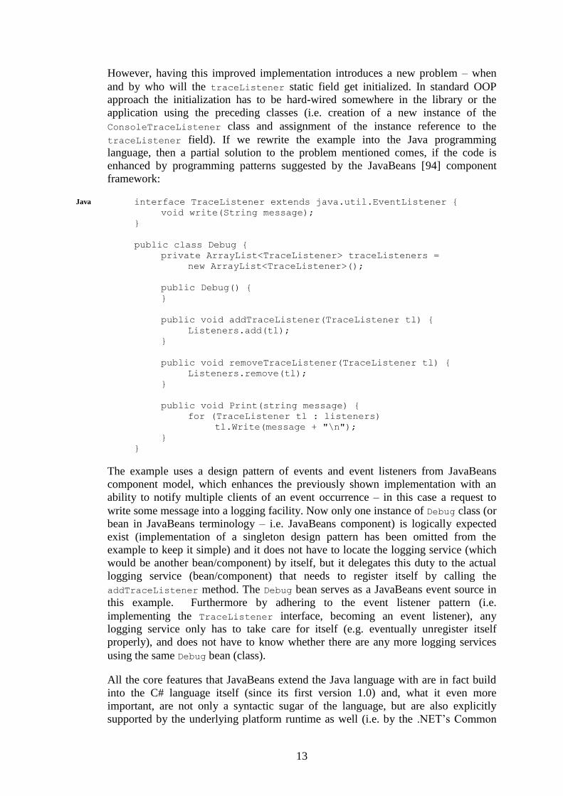
However, having this improved implementation introduces a new problem – when
and by who will the traceListener static field get initialized. In standard OOP
approach the initialization has to be hard-wired somewhere in the library or the
application using the preceding classes (i.e. creation of a new instance of the
ConsoleTraceListener class and assignment of the instance reference to the
traceListener field). If we rewrite the example into the Java programming
language, then a partial solution to the problem mentioned comes, if the code is
enhanced by programming patterns suggested by the JavaBeans [94] component
framework:
interface TraceListener extends java.util.EventListener {
void write(String message);
}
public class Debug {
private ArrayList<TraceListener> traceListeners =
new ArrayList<TraceListener>();
public Debug() {
}
public void addTraceListener(TraceListener tl) {
Listeners.add(tl);
}
public void removeTraceListener(TraceListener tl) {
Listeners.remove(tl);
}
public void Print(string message) {
for (TraceListener tl : listeners)
tl.Write(message + "\n");
}
}
The example uses a design pattern of events and event listeners from JavaBeans
component model, which enhances the previously shown implementation with an
ability to notify multiple clients of an event occurrence – in this case a request to
write some message into a logging facility. Now only one instance of Debug class (or
bean in JavaBeans terminology – i.e. JavaBeans component) is logically expected
exist (implementation of a singleton design pattern has been omitted from the
example to keep it simple) and it does not have to locate the logging service (which
would be another bean/component) by itself, but it delegates this duty to the actual
logging service (bean/component) that needs to register itself by calling the
addTraceListener method. The Debug bean serves as a JavaBeans event source in
this example. Furthermore by adhering to the event listener pattern (i.e.
implementing the TraceListener interface, becoming an event listener), any
logging service only has to take care for itself (e.g. eventually unregister itself
properly), and does not have to know whether there are any more logging services
using the same Debug bean (class).
All the core features that JavaBeans extend the Java language with are in fact build
into the C# language itself (since its first version 1.0) and, what it even more
important, are not only a syntactic sugar of the language, but are also explicitly
supported by the underlying platform runtime as well (i.e. by the .NET’s Common
Java
14
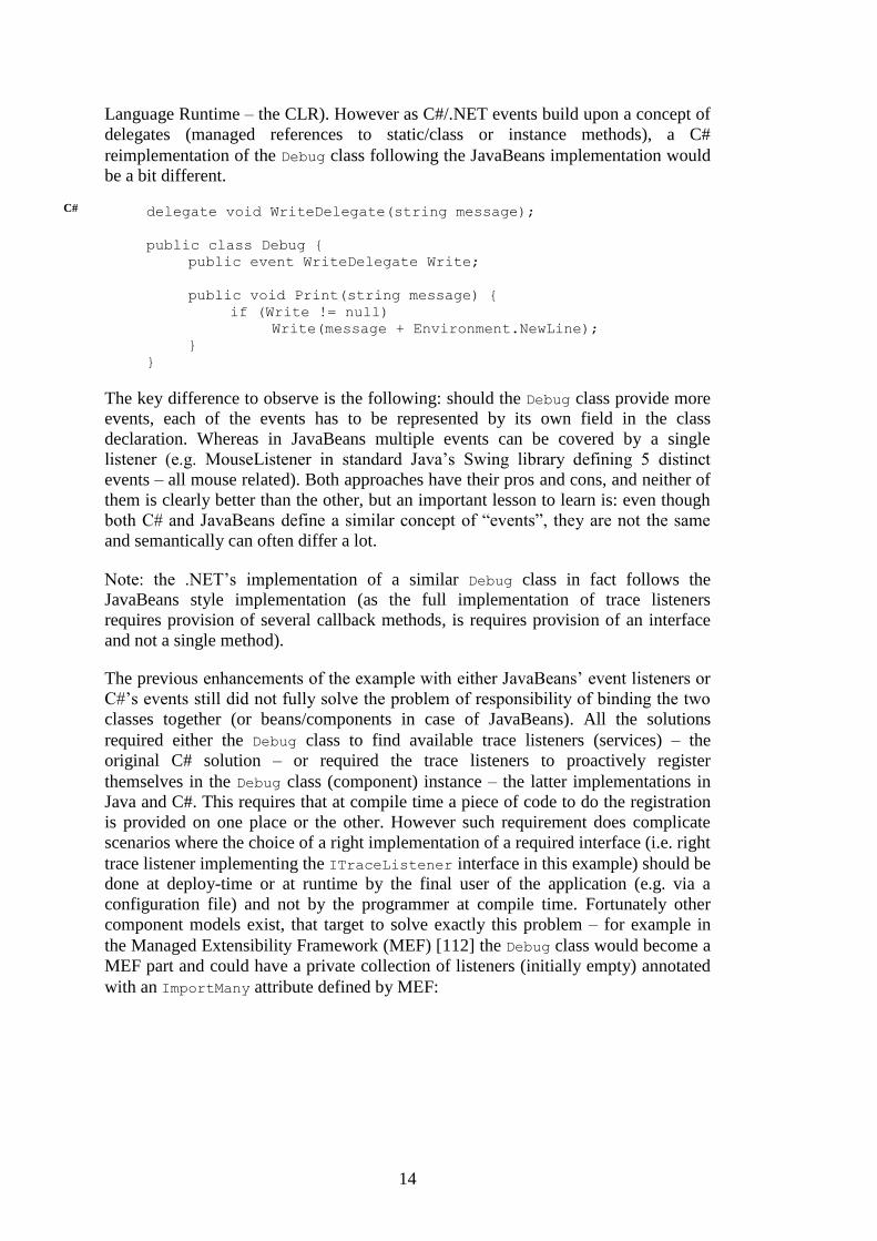
Language Runtime – the CLR). However as C#/.NET events build upon a concept of
delegates (managed references to static/class or instance methods), a C#
reimplementation of the Debug class following the JavaBeans implementation would
be a bit different.
delegate void WriteDelegate(string message);
public class Debug {
public event WriteDelegate Write;
public void Print(string message) {
if (Write != null)
Write(message + Environment.NewLine);
}
}
The key difference to observe is the following: should the Debug class provide more
events, each of the events has to be represented by its own field in the class
declaration. Whereas in JavaBeans multiple events can be covered by a single
listener (e.g. MouseListener in standard Java’s Swing library defining 5 distinct
events – all mouse related). Both approaches have their pros and cons, and neither of
them is clearly better than the other, but an important lesson to learn is: even though
both C# and JavaBeans define a similar concept of “events”, they are not the same
and semantically can often differ a lot.
Note: the .NET’s implementation of a similar Debug class in fact follows the
JavaBeans style implementation (as the full implementation of trace listeners
requires provision of several callback methods, is requires provision of an interface
and not a single method).
The previous enhancements of the example with either JavaBeans’ event listeners or
C#’s events still did not fully solve the problem of responsibility of binding the two
classes together (or beans/components in case of JavaBeans). All the solutions
required either the Debug class to find available trace listeners (services) – the
original C# solution – or required the trace listeners to proactively register
themselves in the Debug class (component) instance – the latter implementations in
Java and C#. This requires that at compile time a piece of code to do the registration
is provided on one place or the other. However such requirement does complicate
scenarios where the choice of a right implementation of a required interface (i.e. right
trace listener implementing the ITraceListener interface in this example) should be
done at deploy-time or at runtime by the final user of the application (e.g. via a
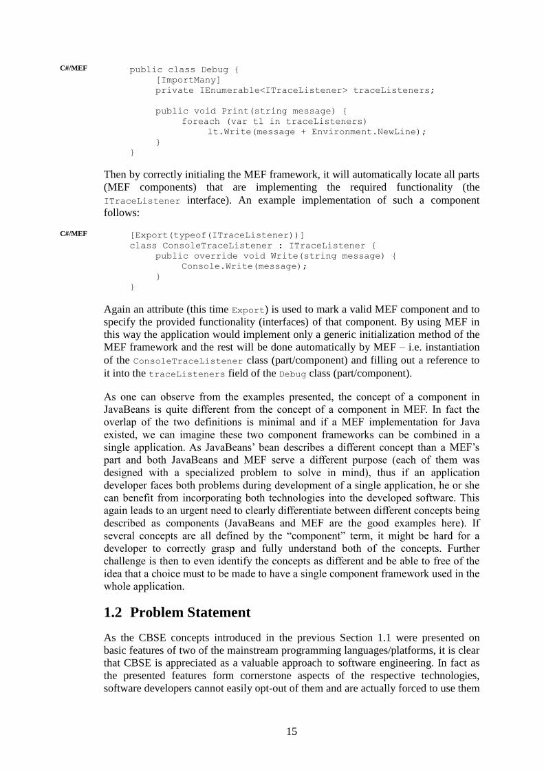
configuration file) and not by the programmer at compile time. Fortunately other
component models exist, that target to solve exactly this problem – for example in
the Managed Extensibility Framework (MEF) [112] the Debug class would become a
MEF part and could have a private collection of listeners (initially empty) annotated
with an ImportMany attribute defined by MEF:
C#
15
public class Debug {
[ImportMany]
private IEnumerable<ITraceListener> traceListeners;
public void Print(string message) {
foreach (var tl in traceListeners)
lt.Write(message + Environment.NewLine);
}
}
Then by correctly initialing the MEF framework, it will automatically locate all parts
(MEF components) that are implementing the required functionality (the
ITraceListener interface). An example implementation of such a component
follows:
[Export(typeof(ITraceListener))]
class ConsoleTraceListener : ITraceListener {
public override void Write(string message) {
Console.Write(message);
}
}
Again an attribute (this time Export) is used to mark a valid MEF component and to
specify the provided functionality (interfaces) of that component. By using MEF in
this way the application would implement only a generic initialization method of the
MEF framework and the rest will be done automatically by MEF – i.e. instantiation
of the ConsoleTraceListener class (part/component) and filling out a reference to
it into the traceListeners field of the Debug class (part/component).
As one can observe from the examples presented, the concept of a component in
JavaBeans is quite different from the concept of a component in MEF. In fact the
overlap of the two definitions is minimal and if a MEF implementation for Java
existed, we can imagine these two component frameworks can be combined in a
single application. As JavaBeans’ bean describes a different concept than a MEF’s
part and both JavaBeans and MEF serve a different purpose (each of them was
designed with a specialized problem to solve in mind), thus if an application
developer faces both problems during development of a single application, he or she
can benefit from incorporating both technologies into the developed software. This
again leads to an urgent need to clearly differentiate between different concepts being
described as components (JavaBeans and MEF are the good examples here). If
several concepts are all defined by the “component” term, it might be hard for a
developer to correctly grasp and fully understand both of the concepts. Further
challenge is then to even identify the concepts as different and be able to free of the
idea that a choice must to be made to have a single component framework used in the
whole application.
1.2 Problem Statement
As the CBSE concepts introduced in the previous Section 1.1 were presented on
basic features of two of the mainstream programming languages/platforms, it is clear
that CBSE is appreciated as a valuable approach to software engineering. In fact as
the presented features form cornerstone aspects of the respective technologies,
software developers cannot easily opt-out of them and are actually forced to use them
C#/MEF
C#/MEF
16
and design software using the CBSE concepts in mind. Even on these few concepts it
was clear the understanding of a component and component-oriented software design
is perceived very differently by orthogonal technologies. There are at least several
dozens of CBSE related techniques in the world from ones coming from the
commercial world (as the examples from Section 1.1) to purely academic or research
ones. Moreover the various CBSE techniques cover a very broad spectrum of
problems and issues from mostly any phase of software development. There are pure
theoretical approaches designed to cope with general software design problems (e.g.
UML components [137]), techniques targeting formal reasoning about software
architecture, dependencies and their functional and non-functional properties (e.g.
Darwin [109] or Palladio [23]), component models combining a formalized view on
software architecture together with support for some advanced runtime features (e.g.
SOFA 2 [40], Fractal [27][3]), component models specialized for a special domain
(e.g. SafeCCM [6], ProCom [158], Koala [171], SOFA HI [160][150][84] for
domain of real-time and/or embedded systems), as well as component systems
designed to “just” simplify some complex day-to-day tasks developer often have to
face during complex software implementation and deployment (e.g. COM [49] or
OSGi [139]), and many, many more. Actually there is not a single rule defining what
techniques fit the CBSE domain, but the other way around is true – i.e. both the
existing and newly emerging techniques define the component-based software
engineering as a discipline. Being that broad and broadening every day, it is not
easily possible to analyze problems related to CBSE in general and in fact it would
not be even reasonable as the theories on opposing sides of CBSE domain are
conceptually so far, it is hard to identify even a single common point, where they
would meet.
Thus for sake of this thesis we will choose just a subset of CBSE, where our
experience and expertise can be mostly utilized to advance the current state-of-the-art
techniques. Our CBSE approach of choice is enhancements of runtime software
frameworks by incorporation of advanced CBSE techniques and provision of
technologies and methodologies bridging the design phase of software development
and the phase of actual code implementation. So our reasoning about CBSE concepts
will be always either directly or indirectly related to some component-oriented
software framework. As a matter of fact the technologies presented in Section 1.1
would fall into such a category.
Even in such narrowed CBSE subdomain, there are still a lot of different approaches
to software design using a concept of a component – an overview of the commonly
used component models can be found in for example in [54] and [107], an overview
of component models specialized for real-time embedded systems can be found in
[88]. If we go through the existing component models, try to gather the features
supported by the models, and divide the features on the typically understood to be
more advanced ones (these are mostly support for complex solutions to most of the
modeling, implementation, packaging and deployment phases of component
developments) and the rest, an interesting observation can be made. The commercial
component models that are widely used in today’s regular software development do
typically incorporate the more “basic” CBSE concepts from the set. On the other
hand the complex features are mostly promoted by the component models with
academic or research background in general.

17
The obvious question one has to ask is what the academic models do wrong, that
they are not able to persuade commercial component model writers of the benefits
the advanced features they can provide. Unfortunately the key problem is probably
inherent to the non-commercial research-oriented framework development – i.e. the
framework are prepared with a vision of providing some new revolutionary features,
but often a vision of a final product is missing. The reason for such state are quite
understandable – the actual advance in the state-of-the-art can be easily sold to the
research community, but quality of the implementation backing the ideas is not
predominant for general good acceptance the research results. Prevailing attitude in
the community tends to underestimate both the importance and overall cost of
implementation of the ideas. It is often perceived the original idea is the key to
success and the transition to the actual code implementing it is quite simple and
every experience programmer can do it.
However software development is not an easy task and especially the with growing
complexity of the technology, it is very important how the implementation is
designed and whether a set of features of the underlying technology has been
carefully chosen with respect to the assignment and the target domain. This can be
nicely summarized with a classical problem regarding algorithm complexity – the
asymptotic complexity matters, but the constants often matter as well in the actual
implementation – i.e. poor choice of instruments of the target platform or incorrect
usage of the provided features can slow the final program (algorithm
implementation) in orders of magnitude (e.g. in case of inappropriate utilization of
system caches) or can render it unusable being inherently incorrect (e.g. a very
typical misuse or misunderstanding of target system memory models – usually wrong
assumptions make about volatile accesses to program variables on weak ordering
memory architectures).
In context of component model this problem arises much more often than in regular
software development. As the advanced features can be often very nicely designed to
seamlessly fit into the existing theory, and their formal specification can be quite
simple, but the actual implementation can be overwhelmingly complex. The reason
for it is the component model runtime stands at the bottom levels for software stack
typically directly interfacing the operating system or the platform in general.
However for the reasons presented above such complex component principles are in
research component models often well-defined only on the conceptual level. And
even if an implementation is provided, integration into existing tools is often not very
well maintained or a complex tool-chain supporting the component software
development is not provided.
A closely related problem is the component models often lack more complex
examples or case-studies that would not only prove the implemented concepts work,
but more importantly also clearly show the benefits of the used CBSE approach and
be able to persuade wider developer community about usefulness and maturity of the
component model. To communicate the CBSE advantages better to the developer
community it is necessary, the existing as well as any new emerging CBSE
principles are validated on close-to-real software implementation. Furthermore, as
the implementation oriented CBSE aspects do not float in the air, or are not
beneficial on their own, it needs to be comprehended the CBSE related research have
to mostly fall into a domain of applied research. Such classification means that new
CBSE concepts need a clear motivation on their applicability especially regarding

18
any potential industrial use or advancements for broader software development
community in general.
1.3 Goals and Structure of the Thesis
Goals: We feel the concepts introduced by many of the current component models
are very interesting and we see their huge potential to qualitatively change the course
of software engineering, even with respect to slow adoption of these advanced
techniques by the software developers’ community as presented in the previous
Section 1.2. However as the advanced CBSE related concepts like hierarchical
components, controllers, connectors, etc. are not in focus of mostly spread software
development frameworks and technologies, we are afraid a lot of the great results of
current research in the domain of component-based software engineering slowly dim
without any broader and deeper attention of developer community and the work of
the researchers it then a bit underappreciated. This thesis aims at helping the CBSE
community to be able to compete with the main stream of software engineering and
bring the interesting CBSE oriented systems’ ideas to real life. Thus, the following
goals of the thesis are proposed:
(1) To identify common features of CBSE design principles adopted in current
technologies, as well as the promising directions lacking wide common
adoption in software industry.
(2) To show key strengths and weaknesses of the component modeling
approaches incorporating promising CBSE principles, especially with respect
to their application onto actual software implementation. This requires
verifying the approaches on real-life case-studies.
(3) To provide solution to most severe of identified weaknesses of the advanced
component modeling approaches (namely hierarchical component models).
Structure: This Chapter 1 provides an introduction to the CBSE domain and
presents a problem statement with regard to current software development with
CBSE concepts and proposed goals of the thesis are stated. Chapter 2 shows current
state of the art publications in CBSE domain sort of inherently imply a general quest
for a holy grail of an ideal component model. The chapter continues with an
overview of a few component models incorporating typical CBSE concepts from our
point of view. The survey of component models is organized in a way, so that it can
be naturally followed up with a summary of goals of different approaches to CBSE.
Finally, the chapter concludes with a need to refine the goals proposed in Chapter 1.
Aim of the following Chapter 3 it to provide a bridge between Chapter 1 and Chapter
2 (more or less covering an extended problem statement) and the rest of the thesis
which is mainly based on published results and on our participation in several
projects and on their results.
As most of the presented results are tackling with a notion of behavioral specification
and verification of its correctness in context of behavior protocols formalism in
context of hierarchical component models, the Chapter 4 provides an overview of the
key behavior protocol concepts that are necessary to comprehend Chapter 5 to
Chapter 7. This introduction to thesis background is followed by chapters presenting
the two major case-studies - Chapter 5 presents an Internet access management
19
system developer as part of a CRE project, Chapter 6 presents our approach to an
assignment of the CoCoME international contest. Chapter 7 then proposes a solution
to the identified need of modeling of dynamic architectures and includes an
evaluation of the proposed concept as well as its applicability on the presented case-
study, whereas Chapter 8 shows an alternative approach to modeling component
environments in context of Windows kernel drivers.
Chapter 9 summarizes the related work from the published papers covering the
presented contribution. As in a limited space of the thesis it was not possible to
provide a definitive solution to all the identified problems, Chapter 10 provides a
short conclusion of all achievements of the thesis, and then Chapter 10 iterates again
through the problems and show the areas where we were not able to provide
sufficient solution. Also some future direction how to improve our solution and
where to advance the research are presented in Section 10.2.
1.4 Contributions and Publications
A novel contribution of the thesis can be divided into several areas, that are covered
in respective chapters of the thesis: (1) an overview of diversity CBSE concepts and
approaches, (2) an analysis of current components models with a runtime
environment and a consecutive summary of component models structured according
to newly identified criteria, (3) an analysis of hierarchical component models’ goals
and motivations, (4) introduction of a case-study and an analysis of suitability of
hierarchical component models and their application correctness verification
techniques in context of two major case-studies, (5) introduction of an approach to
model dynamic entities and architectures changing at runtime in domain of
hierarchical component models, and (6) introduction of an approach to model
component environment.
An overview of published results relevant to context of this thesis follows:
Book chapters
[38] Bulej L., Bureš T., Coupaye T., Děcký M., Ježek P., Parízek P., Plášil F.,
Poch T., Rivierre N., Šerý O., Tůma P.: CoCoME in Fractal, Chapter in The
Common Component Modeling Example: Comparing Software Component Models,
Springer-Verlag, LNCS 5153, Aug 2008
Reviewed articles
[42] Bureš T., Ježek P., Malohlava M., Poch T., Šerý O.: Strengthening
Component Architectures by Modeling Fine-grained Entities, in proceedings of 37th
Euromicro SEAA 2011, Oulu, Finland, IEEE CS, Aug 2011
[95] Ježek P., Bureš T., Hnětynka P.: Supporting Real-life Applications in
Hierarchical Component Systems, in proceedings of SERA 2009, Haikou, China,
Studies in Computational Intelligence (SCI), Springer, Dec 2009
[113] Matousek T., Ježek P.: DeSpec: Modeling the Windows Driver Environment,
in proceedings of FESCA, ETAPS'07, Braga, Portugal, ENTCS, Mar 2007
20
[96] Ježek P., Kofroň J., Plášil F.: Model Checking of Component Behavior
Specification: A Real Life Experience, in Electronic Notes in Theoretical Computer
Science, Vol. 160, pp. 197-210, Elsevier B.V., ISSN: 1571-0661, Aug 2006
[99] Kofroň J., Adámek J., Bureš T., Ježek P., Mencl V., Parízek P., Plášil F.:
Checking Fractal Component Behavior Using Behavior Protocols, presented at the
5th Fractal Workshop (part of ECOOP'06), July 3rd, 2006, Nantes, France, Jul 2006
Technical reports
[41] Bureš T., Ježek P., Malohlava M., Poch T., Šerý O.: Fine-grained Entities in
Component Architectures, Tech. Report No. 2009/5, Dep. of SW Engineering,
Charles University in Prague, Jun 2009
Presentations
Ježek P.: Model-Driven Development on .NET Platform, Model-driven Software
Development in the Real World Workshop, MDD-RW 2010, Karlsruhe, Germany,
Jul 2010
Ježek P.: Behavior Protocols: Formal Specification of Services Behavior in a
Component Environment, 16th Annual Conference of Doctoral Students, WDS’07,
Prague, Czech Republic, Jun 2007
Ježek P.: Behavior Protocols: Using Behavior Protocols to Model Real-Life
Software Components, 15th Annual Conference of Doctoral Students, WDS’06,
Prague, Czech Republic, Jun 2006
Adámek, J., Bureš, T., Ježek, P., Kofroň, J., Mencl, V., Parízek, P., Plášil, F.:
Real-life Behavior Specification of Software Components, 11th EMEA Academic
Forum, Dublin, Ireland, May 2006
Ježek P.: Behavior Protocols: A Real Life Experience, 14th Annual Conference of
Doctoral Students, WDS’05, Prague, Czech Republic, Jun 2005
Ježek P.: Combining OMG Target Data Model and JMX Technology, 13th Annual
Conference of Doctoral Students, WDS’04, Prague, Czech Republic, Jun 2004
1.5 Note on Conventions Used
The text of this thesis is partially based on the papers referenced in the previous
Section 1.4 and manual of the project mentioned below. In order to emphasis this
fact, the paragraphs taken from the papers are in the thesis marked by a side
paragraph marker.
This is an example of a paragraph that is copied verbatim from the published book
chapter, a reviewed paper or a technical report and is marked by a vertical bar.
This is an example of a paragraph that is copied verbatim from the manual of the
France Telecom funded project Component Reliability Extensions for Fractal
component model [2] and is marked by a vertical wavy line. The project manual is
available on-line [3], however has not been previously officially published at any
21
conference or workshop. Contributors to the text of the manual are Jiří Adámek,
Tomáš Bureš, Pavel Ježek, Jan Kofroň, Vladimír Mencl, Pavel Parízek,
František Plášil.
Where it was necessary, the original text is slightly modified to make the thesis easy
to read. But these modifications are only in several sentences at beginnings of the
copied text in order to fit together with the rest of the thesis. Also, phrases like “in
this paper” are changed to “in this thesis”, etc., for obvious reasons. Furthermore the
original text was often slightly reformatted and several small structural changes were
made to fit the formatting and structuring style of the thesis. Also a few typos found
in the camera-ready versions published were corrected in the thesis.
The source of the text copied verbatim is denoted by the margin notes (in the right
margin of the text) at the beginning of the each copied section. We use the following
abbreviations for distinguishing the sources:
CREman for text copied from [3]
CoCoME for text copied from [38]
DeSpec for text copied from [113]
Entity for text copied from [42] EntityTR for text copied from [41]
FACS for text copied from [96]
To further enhance readability of the text, paragraphs comprising only from source
code of a programming, specification or modeling language are indented more than
regular paragraphs and are denoted by the margin notes (in the left margin of the
text) identifying the target language, the paragraph is written in:
This is an example of a paragraph written entirely in the Java
programming language.
Java

22
Chapter 2
Quest for an Ideal Component Model
2.1 Different Views on Basic Concepts
To fulfill the first two goals as presented in Section 1.3 we need to analyze the
current approaches to CBSE. As mentioned before, the CBSE conference is a
respected source of CBSE related papers that usually form or are positioned near the
frontier of state-of-the-art in the CBSE domain. Browsing through the papers
published at CBSE conferences in recent years one can easily notice that most of the
papers sooner or later in the text end up by anchoring themselves in the CBSE
domain by defining a notion of a component or CBSE itself. The motivation is
natural as to be able to reason about CBSE concepts and to provide some
enhancements to the domain, it is necessary to have a clear understanding of what the
concepts are and where the paper results are applicable. While most of the papers
provide just a short definition of CBSE or a component (often just referencing
relevant definition in literature) and thus implicitly postulating their authors’
assumption of fundamental roots of CBSE as being well-established without any
need to further elaborate, the authors of few other papers are obviously aware of a
complicated situation regarding a clear and sound definition of a component, and are
trying to provide an analysis of various CBSE approaches to show a relevant CBSE
subdomain, that their results fit in (thus providing a more constrained view of
CBSE). As the third goal of this thesis expects us to provide a solution to some of
CBSE related problems, it is for us also necessary to define an area of software
engineering, where we believe our results can be ideally applicable.
In Sections 1.1 and 1.2 we have shown the basic CBSE concepts (mainly a concept
of a component) are not that clear as one would expect. On the other hand as
mentioned in the previous paragraph authors of many CBSE related papers do not
feel the same way and present or reference their “generic” definition of a CBSE
component. One of the most cited one is the component definition by Clemens
Szyperski as presented in his book “Component Software – Beyond Object-Oriented
Programming” – as it requires more analysis, a reference will be given in Section
2.1.1 which presents some problems regarding the definition. Another commonly
referenced definition of a component is the one by Heineman and Councill from
[81], Section 2.1.2 is dedicated to analysis of problem related to this latter definition.
2.1.1 Issues with Szyperski’s Definition
Typical references to Szyperski’s book unfortunately introduces already first
problem – while a verbatim copy of Szyperski’s definition is often presented, some
papers only reference the book as such. By carefully reading the book reader can in
fact find two different component definitions there (so that if a paper references just

23
the book itself, it is not clear which definition had the authors in mind). The first
definition of component presented in [167] is partially implicit by stating a set of its
characteristic properties:
(1) “A component is a unit of independent deployment.”
(2) “A component is a unit of third-party composition.”
(3) “A component has no persistent state.”
Presented in the 1997’s print of the book these properties reflected the contemporary
Szyperski’s insight and personal view on software components. As he later admitted
over the years (with the evolution of the software engineering domain) he gradually
shifted to slightly different understanding of components as is reflected in an updated
definition of component presented in second edition of the book [165]:
(1) “A component is a unit of independent deployment.”
(2) “A component is a unit of third-party composition.”
(3) “A component has no (externally) observable state.”
Although the definition is presented in the book first, we understand it more as an
explanation or annotation of the second component definition presented later in the
book. Having its own subsection the second definition can be probably considered as
the grand-definition of component (which can be incidentally supported by a fact,
that should a Szyperski’s component definition be provided as a verbatim copy in a
paper, it would be this second one). While the first definition was updated between
editions, the following one has remained the same throughout the years (in both
[167] and [165] editions of the book):
“A software component is a unit of composition with contractually
specified interfaces and explicit context dependencies only. A
software component can be deployed independently and is subject to
composition by third parties.”
And as it is stated in the book, the above definition is in fact an outcome of a very
deep and long discussion in one of the workshops of 1996’s European Conference on
Object-Oriented Programming (ECOOP) and was originally published in [166].
One can observe that the both definitions are quite general – in fact as noted for
example in [80], a component defined by properties of “a unit” does not necessarily
imply any connection to software engineering (so it can define a hardware
component as well), nor even any connection to the computing world in general at all
(thus being valid in potentially any domain with suitable “units”). The book presents
a very thorough discussion on the topic; the definitions were carefully prepared as a
result of an intensive research of the contemporary component-based systems and
general state-of-the-art of CBSE as well. However when trying to analyze current
software component-oriented software systems based on a provision of a runtime
environment/platform, it will soon become clear that many of the systems do not
fully fit with their approach to component modeling the definitions presented so far
(in spite of their generality mentioned above). In fact, one could say that these
24
“problematic” component systems and their components do not conform to the
definitions, as often one of the key requirements on a software component does not
hold in the respective component system. Few examples of such inconsistencies with
Szyperski’s definitions are as follows:
One of component-oriented systems commonly considered in published CBSE
related papers is the JavaBeans [94] component model. One of the explicit
requirements on a JavaBean (bean = a JavaBeans’ component) is that it has to expose
parts of its internal state via properties – which is in a direct contradiction with the
(3) rule of the updated version of the first Szyperski’s definition of component (“A
component has no (externally) observable state.”). One might argue the properties
can be viewed as an optional feature of a bean and that a bean without properties
(thus with only internal state) can exist – but such a bean would go directly against
the JavaBeans’ basic concept, since beans are designed to encapsulate units of user
interface interaction (UI components), where state sharing between a component
(representing a subset of possible user interaction – gathering parts of user input and
providing features for user output) and its environment is the key way of interaction
between components. Windows Presentation Foundation (WPF) [132], Silverlight
[130], Metro UI API for upcoming Windows 8 OS [131] are examples of graphical
user interface (GUI) frameworks that are even more data oriented and the data
exposed by respective UI components play there even more important role than in
JavaBeans. In these technologies, the interaction with the user is not (only) defined
by application’s code, but by application’s data relations as well (the relations are
expressed as connections – or connectors – between the components the application’s
architecture is built from) – and this focus on the data is believed to be the key
success point of these technologies. This implies the data-centric approach of
component frameworks targeting UI development should in fact strengthen in future
and not weaken as Szyperski’s definition suggests.
Furthermore component systems not able to fully fit the second Szyperki’s
component definition can be also identified. As statistics of web browser popularity
[174] show the Windows operating system with market share of 83.9% as of January
2012 is still the most popular operating system on desktop computers (assuming the
vast majority of desktop systems is connected to internet and is used to regularly
access the world wide web). And COM [49] component model being a cornerstone
of many basic application-to-OS and application-to-application interactions in
Windows OS is, at time of writing of this thesis, probably the most commonly used
component system in the world. The COM is based on the exposure of well-specified
interfaces that define an interaction point between components. Even though a COM
component does have “contractually specified interfaces”, it does not have “explicit
context dependencies only” – in fact the component’s dependencies are rarely
defined explicitly, a common approach is the dependencies are implicitly given by
the code that tries to instantiate required components at runtime.
Yet another problematic example is “the .NET components”, as the CBSE concepts
are incorporated in many aspects of the .NET platforms. These different component-
oriented aspects of .NET are however not directly related to each other and in fact
exist on different levels of abstraction. That is why the phrase “the .NET
components” is quoted in the first sentence of this paragraph. Unfortunately this is a
common problem of many CBSE related papers as their authors often do reference
“.NET (components)” (without the quotes), but to not specify exactly which
25
component concept of the .NET platform they have in mind. We will get back to this
problem later, so for now let’s assume a .NET component equals to a .NET assembly
(as Szyperski does in his book) – a simplified view is that an assembly is a unit of
binary code distribution and deployment on the .NET platform (typically it is a single
EXE or DLL file, but multi-file assemblies can exist as well).
Even if considering only the assemblies as .NET components, a problem with their
view as Szyperski-style components arises. Whilst .NET assemblies do have
explicitly specified dependencies (each assembly contains a list of required
assemblies in its so-called manifest), the problem lays in the “a unit of composition
with contractually specified interfaces” part of the component definition. The
interface of an assembly as a unit of composition is just its “strong name” (in terms
of .NET: plain text name, version, its language of localization, and cryptographically
unique publisher’s ID) – i.e. relationships among assemblies as defined by their
mutual requirements are explicit only in sense of their names and not their actual
contents. However the assembly’s contents defines its true contract – i.e. all the
features the assembly provides – and, as such, it does not form the assembly’s
interface. Furthermore, even if the contract was understood to be a part of the
assembly’s interface then the assemblies as components will get in conflict with the
“explicit context dependencies only” rule, as the actual dependencies on another
assembly’s contents are provided only implicitly in the assembly’s code.
Interestingly enough, these dependencies are not even verified during assembly
lookup process done by the Common Language Runtime (.NET’s virtual machine)
[89][63], nor during loading a dependent assembly into process memory. The
dependencies are always verified only lazily at the time of their actual need during
application progress. Though such a feature might seem very odd from point of view
of a software engineering theoretician, it makes a perfect sense in the world of real
life desktop applications. Namely the lazy dependency verification allows silently
ignoring any missing dependencies (e.g. missing classes, methods, etc.), and
postponing any potentially fatal errors until a request to use such a missing feature
arises. In a typical desktop application this approach manifests itself by a very user-
friendly behavior, where an application with missing dependencies would start
usually start without problems and if a user does not click (for example) a menu item
accessing the missing dependency, he or she will not notice any application usability
problems.
2.1.2 Issues with Heineman and Councill’s Definition
It seems that trying to define the CBSE by establishing a component concept by its
own is not the best direction. In reality the component abilities, behavior and
constraints are tightly coupled to the component technology being considered. Thus
it seems an opposite view on a component definition should be taken, i.e. not to try to
define a component in isolation, but try to define it with respect to its context.
Fortunately others already came to a similar conclusion, and for example Heineman
and Councill in [81] provide a relevant definition of a component model as an
abstraction of specific component context:
“A component model defines a set of standards for component
implementation, naming, interoperability, customization,
composition, evolution and deployment.”
26
Having a component model defined this way component can be now redefined with
respect to that component model definition – such component definition reads [81]:
“A software component is a software element that conforms to a
component model and can be independently deployed and composed
without modification according to a composition standard.”
This definition of component does not enforce very specific constraints, and it rather
leaves an exact definition and constraints to the specific component model the
components are considered in. Being so open, it allows a component model to freely
define components’ constraints to fully fit its goals and needs, for example, as a bean
conforms to the JavaBeans model’s specification and as much as a COM component
conforms to a COM model’s specification, both JavaBeans and COM components
(not conforming to Szyperski’s component definitions) do conform to Heineman and
Councill’s component definition.
On the other hand, strictly speaking, the .NET assemblies viewed as components
might not adhere to the Heineman and Councill’s component definition, as their
(contract) modification via publisher’s policy, or user/machine configuration might
be required to allow them to participate in specific composition scenarios.
Unfortunately Heineman and Councill’s component definition is not as trouble-free
as the previous text might imply (the note above shows a sign of a potential glitch).
The key problem of the definition is that it silently expects from the reader some
previous intuitive understanding of the concept of component model and component.
Let’s illustrate this on an example:
The Java programming platform represents a quite broad spectrum of concepts – for
typical cases four of them form the key parts of the platform: (1) the Java runtime for
execution of Java binary code (i.e. the Java Virtual Machine or JVM [91][93]), (2)
the binary code to be executed in context of a JVM itself (i.e. the Java bytecode
[91][93]), (3) the Java programming language [91][92] (i.e. textual notation of a
typical programming language used to create programs for the Java platform – to be
compiled to Java bytecode), (4) the Java standard library (i.e. predefined set of code
artifacts distributed in binary form of Java bytecode). The Java programming
language defines some constraints on the structure of the source code – one of them
being a rule of exactly one package public type per a Java source file and any
number of package private classes per a Java source file – a Java source file is a plain
text file typically with a .java file extension. In a binary form the code is divided
into separate class files (files with a .class file extension) – where each binary
class, either public or private, resides in its own class file. An important note is that
the Java programming language and the Java bytecode are two generally unrelated
concepts on different levels of abstraction - i.e. Java source code can be compiled
into other binary forms as well (e.g. to .NET’s CIL intermediate code [89][63], or in
a more typical case to Dalvik bytecode [56] of the Android [11] platform), and other
then Java programming language source codes can be compiled into Java bytecode
(in fact currently there are many newly emerging languages for the Java platform –
common examples would be Scala [156][157] and Groovy [79] programming
languages).

27
Though a JAR file (Java Archive [90]) is now in most cases a typical unit of
deployment of binary Java code, for the JVM core a Java bytecode class is a most
basic unit of code loading and thus of deployment too1. From JVM’s point of view a
JAR file is just an optional simplification of bytecode class file distribution. As JVM
imposes the rules all Java bytecode classes have to adhere to, if we defined JVM as a
component model (according to Heineman and Councill’s definitions), then any Java
bytecode class would be a component. However, there is something obviously wrong
here as, common sense dictates that plain classes should not be equivalent to
components as it would make explicit definition components redundant. As
mentioned before, the problem lays in the Heineman and Councill’s definition
expecting an implicit understanding of a component model. A typical CBSE
developer with a good knowledge of a CBSE domain would obviously did not define
Java classes as components as he or she would expect some added value for the
classes to become (a part of) components.
A clear conclusion that can be summarized from the previous paragraphs is that a
commonly accepted opinion that a component definition clearly defines the CBSE
can be unfortunately easily refuted. The presented and commonly referenced
definitions of a component are (a) either too strict, so that software frameworks also
commonly considered as component frameworks do not fit them, or (b) too general,
so that many other concepts and frameworks fit the definition. Though the presented
definitions of components are not the only one and in fact many tens of them exist all
around in the literature (a nice summary of several other common ones can be found
in [149]), they all inherently share the same problems mentioned. While any too
generalized definitions are not useful to fulfill our goal of ultimately be able to define
a CBSE domain where certain technological enhancements can be applied, having a
too strict definition in fact can help to define exactly such a subdomain of CBSE.
In this sense the Szyperski’s definition can be used to differentiate compatible
component models that do fit the definition and the others. However the problem is
that the definition is not perceived as defining a subset of CBSE instead of the whole
CBSE (the definition’s wording itself suggests it is aiming at defining component in
general). Thus referencing the Szyperski’s definition to define a CBSE subset only
would be probably misleading as it would be often misunderstood as just a regular
whole CBSE problem domain definition (as the many papers show, by mixing both a
reference to this definition and referencing component models being in conflict with
it).
2.1.3 Issues with Categorizing Component Models
Instead of a common all-encompassing component definition it looks more
promising to try to find some common characteristics of component models. Each of
these potentially identified characteristics would then form a separate definition of a
component feature. Using these multiple component-wise definitions, component
models can be classified into separate categories according to some rules defining
compliance with these characteristic features. In fact this is not a novel idea and a
1 When loading the individual Java bytecode classes the JVM behaves in a similar way as the CLR (.NET) does
in context of its assembly components. Java class files does not have any explicit dependencies on other classes
and any external dependencies are discovered only at runtime as the JVM lazily loads the classes required by
the code (i.e. the external dependencies are implicitly stated in the code – similar as in COM or .NET
assemblies [if considering the actual assembly contract, as mentioned before, the assembly exported types]).
28
few very thorough papers have already been published providing exactly such a
component model classification, see [54][107]. If trying to use these papers as basis
for defining a CBSE domain, where a certain additional feature can be implemented,
one can very soon run into problems again. Let’s illustrate it on a few examples
presented below.
In [107] authors present JavaBeans as a component model where “components are
classes”, while COM component model is assigned into a category of component
models where “component are objects” according to the methodology used in the
paper. However as the JavaBeans are in facts just introducing missing features to the
underlying programming language of Java, the execution model has to retain the
same properties as the underlying Java platform has. Though in the proposed new
version of JavaBeans the basic idea of a bean is more complex (allowing multiple
classes to implement a single bean, etc.), the proposal is on the table for several years
and it’s not probable it will be ever brought to life. And in the current version of
JavaBeans a bean (type, i.e. component type) is just an enhanced Java class, i.e. an
entity that has to be explicitly instantiated at runtime to get an object instance.
However exactly the same is true for COM components – if a COM component is
implemented in C++ programming language then a component type is a C++ class
(in fact, a component type is named a class in COM terminology and is identified by
a unique class ID). Only at runtime such a class is instantiated into a component
instance by explicit call to CoCreateInstance function or similar (accepting the
unique class ID as an identifier of a component to create). There is obviously a glitch
or misunderstanding somewhere if JavaBeans and COM are classified differently
vis-à-vis a classes versus objects criterion in [107] – unfortunately the reasoning
behind such a conflicting classification is not presented in the paper.
Similarly in [54] the JavaBeans are classified as having explicit distinction of
provided and required interfaces. Thought the topic is in general discussed in the
paper, this specific decision is not clarified there. While there can be many different
views on specific component model features, we understand the JavaBeans
dependencies differently. Services provides by a bean are defined by interfaces it
implements (provided interfaces), and while a bean can be externally connected to
another bean, should a bean require services of another bean the requirement would
be present implicitly in the beans code. Thus only the provided interfaces are
explicitly given, which is similar to the COM component model, and also behaves
and has same implications as dependencies between “.NET components” (the
problem of their missing requirements were discussed above).
Another challenging point of [54] paper is a claim that “a component is executable”.
While an exact definition of executable code is not given, the paper elaborates the
statement with a footnote: “Executable property does not necessarily mean binary
code. For example the execution can be achieved through an interpreter or by a
virtual machine, or even through compilation before the execution”. This clarifies the
authors’ understanding of executable code, but does not provide reader with exact
definition. Even though the text implicitly permits looser interpretations of
executable code and environment, from the choice of the component models we feel
the authors tend to give precedence to a more typical algorithmic or imperative-wise
concept of executable code. This might however contradict with some modern
approaches to component-oriented software development where a more declarative
way of behavioral description is often preferred. If the JavaBeans component model
29
is considered then other graphical component frameworks should be considered as
well, so the reader can get a better understanding of the common CBSE related
concepts – an example can the .NET platform with its WPF (Windows Presentation
Foundation [132]) framework, where an application can be created from visual
components just by declaratively instantiating and interconnecting them, while also
providing data-driven behavioral dependencies between them. In extreme cases an
application can be there created just by XAML-only assemblies (enhanced instance
of a XML meta-format) without any regular executable code.
As both these papers cope with many component models and present many different
views on them providing a detailed elaboration of many CBSE related aspects, the
examples above might seem marginal inconsistencies without any serious impact. On
the contrary an important observation they imply can be made: Even being an expert
on CBSE and thus having an excellent understanding of component modeling
concepts is sometimes not enough when coping with real-life component models
having many target language, platform or domain specifics. And as it is hard to
become an expert of a specific component model, when someone tries to reason
about one while having a specific understanding of CBSE concepts, he or she tries to
map any new or unusual component model’s concepts to these previously known and
understood ones, as well as abstract any very specific implementation details. The
problem is such a generalization can then hide an important aspect of the new
concept that can induce a thin, but impenetrable, barrier that stands between practical
applicability and inapplicability of a new general component model feature idea.
Unfortunately this leads to a pitfall of any summarizing paper that would try to
categorize or classify component models into a reasonable number of generic easily
understandable categories. As an inexperienced reader (i.e. non-expert in a specific
domain – i.e. example of the reader targeted by a summarization paper) can easily
draw false conclusions from it and imply some statements for a set of component
models that are not true.
The problem is not inherently in the classification process itself, but it lays in too
abstract or generalized categories. Should the categories be selected to closely match
the actual component model and its components implementation aspects, it should
mitigate the problem. While papers [54][107] have their own motivation on selection
of the classification criteria and are as exhaustive as possible in their component
model selection, we believe that to be able to provide a brief summary of component
models considered with respect the their features related to their runtime
environment (see Section 2.4), we need an alternative approach to component model
classification (see Section 2.3).
Up to this point we aimed at fulfilling the first two goals of the thesis (as presented in
Section 1.3) by analyzing the CBSE engineering domain, i.e. our initial believe was,
we can first grasp the key CBSE concepts and with their good understanding apply
them on commonly used component frameworks and to reason about them. This
approach however does not seem to get us any closer to providing a solution to the
proposed goals, as the CBSE concepts definitions leads to much confusion and as
shown above it needs an interpreter to give it a correct meaning in context of each
and every component model. As the real component-oriented technologies are in fact
our main focus after all, the opposite direction to the component technologies
analysis should be more feasible.

30
2.2 Conceptual Evolution of “Component”
With the wide range of definitions of component identified in Section 2.1 it is quite
hard to grasp a component based software engineering (CBSE) as a single well
defined technique. However if we look at the mentioned definitions from a further
perspective a common goal begins to unveil. All the definitions at least implicitly try
to define themselves vis-à-vis classes, a key concept of the object oriented
programming (OOP), leading to CBSE positioning itself as an enhancement of OOP.
If we try to order the definitions causally, it can be observed the older concepts are
more and more considered a standard and are superseded by newer (from a specific
point of view, more advanced) concepts. We believe this continuous shift of
component paradigm emerges from the continuous evolution of OOP languages and
their runtime environments, and an ongoing desire of the CBSE community to
further improve developers' experience in developing of software applications. At
least several stages of the CBSE evolution can be identified – they are structured
according to the original motivations behind the component concept introduction to
the software engineering:
2.2.1 Component = Class and Beyond
In the early days of Windows programming, there was a strong demand on bridging
the gap between multiple OO programming languages like C++, Visual Basic or
Delphi – all sharing a similar concept of class, but implemented differently in each of
them. This led to the notion of components as classes enriched by concept of binary
code compatibility as defined by the COM component model. The COM defined a
required organization of classes in memory, i.e. most importantly the format of a
virtual method table (VMT) and its localization based on knowledge of a class
instance reference. Furthermore COM defines another now standard OOP concept
not commonly present in programming languages of that time – a concept of an
interface. And as with the classes themselves, a specification how interfaces should
be implemented on binary level is provided (including support for implementation of
multiple interfaces by a single class – which must have been make with languages
without multiple inheritance [e.g. Pascal] in mind). There two concepts together with
ability to portably specify metadata of a OO program or library (in form of so called
Type Libraries or TypeLibs for short) allowed increased penetration of OO
programming concepts into regular software development. In this view a component
is simply a class that follows some constrains and is as such portable at binary level
(all of this implemented only using concepts already supported by programming
languages).
Such a specialized concept however became inherent part of OO environments with
a wide spread use of Java and .NET languages, or more precisely with use of Java
Virtual Machine (JVM) and Common Language Runtime (CLR) runtime
environments having the binary code compatibility and code’s metadata specification
as the defining features of the platform. It is worth noting that during design of the
.NET platform, aiming at supporting very diverse set of programming languages, it
became obvious that a common subset of language features would be quite small (in
fact similar to the set of concepts supported by JVM), which would lead to more
complicated porting of some advanced languages and it would be hard to incorporate
many state-of-the-art software design concepts. So in order to support both
31
contradicting goals (seamless code compatibility and support of variety of
programming languages) the set of supported language features had to be divided
into two categories – (a) features complying a so called Common Language
Specification (CLS) required to be supported by all .NET languages (all public API
in .NET world should be ideally CLS compliant) and (b) the rest, that can be
optionally supported by .NET languages and that should be primarily used to
implement private (non-public) code.
2.2.2 Component as a UI Building Block
As the arrival of Java environment rendered distinction components as units of
binary compatibility unnecessary, components, as a term, became unbound to any
specific concept. The Java programming language was devised as a clear and sound
language with minimum of concepts - however, it was found quite early that some
concepts are missing from the language, should it be employed in some specific
types of applications – mainly development of applications with a graphical user
interface (UI). In an UI development process, developers typically expect an
integrated development environment (IDE) to be able to help them visually design
graphical look of an UI application. This requires the IDE is able to gather
information about settable properties of UI controls and ideally register developer's
code as reactions to events responding to application's user actions. And these are the
key concepts introduced by the JavaBeans component model and thus defining a
component as a class with explicit properties and events (again implemented only
using concepts of the underlying Java language). The current use of .NET
environment however again made this explicit distinction of components
unnecessary as the concepts of properties and events are the core features of the CLR
and all the programming languages have to support them. Furthermore it is
recommended that all the classes use these concepts (i.e. all of class’s data should be
exported via public properties and not public fields, listener design pattern should be
implemented exclusively via events) as the standard .NET libraries do. Thus in this
sense all .NET classes are components in JavaBeans’ point of view.
On the other hand the .NET platform itself a concept of “components” – again
related to development of application’s UI and its design in IDE. .NET components,
i.e. classes implementing IComponent interface have two main features: (a) explicit
knowledge about their location in applications architecture – identified via a
reference to an implementation of ISite interface – i.e. ability to perceive the
context in which a component is used and to be able to behave or layout itself
accordingly, (b) knowledge of mode of component instantiation (at runtime or at
design time), i.e. whether a component instance should exhibit its standard behavior
(at runtime) or it should behave more as a design editor for itself (at design time).
Even so the general goals of .NET components and JavaBeans are the same, just the
underlying platform implied a different view on a UI component concept.
2.2.3 Component as a Unit of Deployment and Versioning
For at least two decades the world of Microsoft Windows had to live with a very
serious problem arising from implementation of better software engineering concepts
– more precisely software modularization. Developers quickly learned to take
advantage of Windows dynamically linked libraries (DLLs) and almost every
32
Windows application sets off some of its functionality into separate libraries. One of
the key advantages of DLLs perceived at that time was, that if multiple applications
require a same functionality, its implementation can be share among these
applications via a common DLL library. Applying this approach both saves the
overall disk space occupied by all applications installed on the system (as the shared
code does not have to be present multiple times) and any future updates of a library
can be done centrally on one place for all the installed applications.
During the 90’s (being the time of a large shift of users to Windows operating
systems) as software was becoming less and less constrained by hardware limitations
(with fast growing storage capacities available commercially to end-users) and with
an emerging phenomenon of Internet, priorities for applying DLLs began to shift in
benefit of ease of software updates. As data sharing was spreading and more and
more computers were available on-line, computer viruses, Trojan horses and
malware taking advantage of software bugs in general began to spread as well. Thus
software had to become more dynamic, i.e. discovered bugs had to be corrected as
fast as possible before they can be abused by remote computer attacks. At first glance
the concept of shared libraries seem to be perfectly suited to such a scenario as if a
bug is present in a library then all applications using that library are updated at once
by a single update of it. Unfortunately this is a very idealistic view of software as the
new versions of software often break backwards compatibility with any of its older
versions. This problem is inherent to the update process in general and cannot be
simply solved, which can be shown on a simple, yet unfortunately very typical
example: if a bug is discovered by an application developer before its discovery by a
library developer, the application has to come somehow with it; then if in a new
version this bug is corrected, the original application often breaks as the library
begins to behave differently (the bug was accepted as a feature by the application).
Furthermore with an increasing popularity of software platform, thus increasing
amount of available applications for that platform, there is also an increasing number
of misbehaving installation programs that simply always copy all the required
libraries to the target system. If another application depending on a same library is
already installed, such rude installation process can lead to overwriting of a global
copy of the library with its older version – in most cases leading to breakage of the
original application installed.
This problem of single globally shared copy of a library leading to the problems
mentioned is in context of the Windows operating system typically referred to as the
“DLL hell” problem [9]. Should the libraries in a system be shared, the obvious
requirement to solve the DLL hell problem is to be able to transparently support
parallel (or side-by-side) installation of multiple versions of a single library at the
same time. The first solution to the problem was on the Windows platform again
provided by means of COM components that explicitly support component and
interface versioning.
It is quite surprising that authors of the Java language and Java Virtual Machine were
not aware of this problem, and did not provide a solution for it as a standard part of
the Java platform [86]. However a need for such feature in the Java world is as strong
as it was before in the world of Windows application development. This led to
several external solutions emerging in parallel to the basic Java platform. Currently
the most spread one is the OSGi component model (as already mentioned in Chapter
33
1, OSGi is currently heading to be a part of the Java platform in future versions) –
while OSGi defines several concepts, the most basic one is a concept of a bundle (an
OSGi component), which is exactly a unit of versioning and deployment in OSGi.
The OSGi platform also defines a sophisticated means of inter-bundle dependencies
and ability to locate and load all required bundles and in correct order. On this basic
level the OSGi serves a very similar purpose as assemblies on the .NET platform,
that (though being an inherent part of the .NET platform) also provide a solution to
the problem described in this section for the .NET platform, as OSGi does for the
Java platform.
2.2.4 Component as a Service
More than a decade ago as enterprise systems grown larger and more complex and
also became more interconnected to Internet solutions, a strong pressure on better
software engineering approaches especially designed according to needs of enterprise
systems became apparent. The systems’ need to serve many purposes was leading to
a need of better code structuring and ability to easily reuse existing code in new
applications. Further as the systems became more globally available (also increasing
their size) the requirements on the systems’ implementation started to change in the
enterprise domain, aiming to solve problems related to especially high availability
and scalability of the systems.
This led to a new view on software components, where the important features were
the ones that allowed large magnitude of connected clients to the component-based
application, easily incorporation of external components (running on different
computers on the Internet), ability to easily load balance the system providing the
application services in cluster systems. Several component systems targeting such
this domain were introduced, among the most commercially used ones is the EJB
[65] component model in the Java world, and later introduced COM+ [48]
component model for native Windows Server based enterprise application. These
component models give the following features of components the main priority:
(1) Remote components: Ability to publish components and allow remote access
to their provided interfaces. In general an ability to create distributed
applications just by wiring inter-component bindings between multiple
computers. While this feature was already present in component
technologies before EJB and COM+ (thus it is not a defining feature per se),
we have included it in this list as it is a key to meaningfully support the rest
of the features.
(2) Stateless components: All the state is maintained by a client and all
necessary information about the state is transmitted with every request to a
component with allows high scalability by greatly reducing a component
size, while providing ability to reuse components for multiple clients without
problems of state synchronization.
(3) Queued components: Communication with components is not in a form of
direct method calls, but is handled as messages transmitted via a message
queue service and received by possibly multiple copies of a component. This
decoupling of client components from server components (requires from
provides) increases system scalability by giving clients a single point of
34
communication in from of a message queue and allows server to change
number of servicing component according to actual system load, also
allowing for easy dynamic update on server side without any need to reject
client requests (which are automatically postponed in the message queue,
should a target component be currently unavailable – e.g. undergoing an
update process).
(4) Transactional components: Support for transactions on a component level
means not only support for distributed transaction and components being
automatically enrolled in active transaction along a sequence of calls
between components, but also closely related to the previous point. If a
message queue is transactional as well, it will allow automatic recovery in
case of component failures (e.g. unexpected exceptions thrown from
methods, etc.). Should a component fail, the original message it was
processing is still stored in the message queue and another instance of the
component can try later to reprocess it again.
(5) Persistent components: To support long running client sessions and reusing
system resources components with inner state can be saved to a persistent
storage (persisted) and unloaded from memory. This not only allows system
to actively maintain in memory only state for currently communicating
clients, but also allows for seamless system restarts for maintenance or
component migration.
While both EJB and COM+ are commonly perceived as component models, from the
list of the features we can see that currently they should be rather perceived as
service frameworks – as the features described above are now considered a
cornerstone of software services. The development of service-oriented applications is
currently considered a specific software engineering domain – domain of Service
Oriented Architectures (SOA) – that studies the problems typically originating from
the key features of software services. However as shown above the SOA and CBSE
are not two distinct approaches, but can be in fact seen as different points of view on
a same problem. It implies that CBSE is not only black and white, but must be
viewed very broadly, and even technologies that do not explicitly work with
components can be evaluated in CBSE context and some CBSE techniques can be
applicable to them as well – an example can be the Windows Communication
Foundation framework introduced in .NET 3.0, which is a natural evolution of
COM+ as a service-oriented framework for Windows platform – and in fact
obsoletes COM+ (do not confuse it with pure/basic COM which is still an up-to-date
component-based framework for native Windows applications): if COM+ is viewed
as a component model the same should apply to WCF, even though WCF only
describes and works with “services”.
Moreover even specific technologies can change and during their evolution process
can gradually move between SOA and CBSE views on application engineering. The
reason is that as the software platforms change in time, so can the motivations of a
component model change to compensate. An example can be the EJB component
model – where is an important change in many basic concepts with EJB version 3.0.
The technological shift since the first version of EJB, let to gradual change of
motivations and priorities of EJB designers, which finally led to a shift in the base
EJB component concepts as well. While originally the EJB was a mixture of several
35
software engineering approaches, the specification since version 3.0 clearly accents
the service-oriented features as described above.
2.2.5 Component as a Unit of Dependency Injection
As typical desktop applications have grown larger and larger it has become more
obvious that traditional development techniques do not provide enough flexibility to
allow coping with the growing complexity effectively. While technologies like OLE
or ActiveX components brought the unseen possibilities at the time of their arrival,
their primary goal was to allow a smooth composition of more complex applications
from 3rd
party components during the application development. These technologies
were cornerstones of the first public component repositories or stores, were
necessary components for application development could be purchased and
downloaded from (as mentioned in [165]). This simplified typical desktop
application development process as the ActiveX components were ready to use, it
was possible to seamlessly compose them into the application being developed.
While this was an important step forward the classical approach to composition
remained in place, i.e. any respective ActiveX components an application is built
from were very tightly coupled or glued together by the application’s main code (it is
the same approach as is used to compose a GUI oriented application from JavaBeans
components). Important note here is that only the development process for
applications designed in such way is greatly simplified – after the application is
deployed, its configurability is very limited (while it is still composed from
components at runtime, any component interdependencies are given at compile time
and as such these applications can be viewed as monolithic at runtime).
The problem is that in recent years there is a new trend in desktop application
domain to allow much greater customizability or extensibility by the end-users. It is
often motivated by several reasons, two of them being: (a) to give the application
producer option to provide end-users with much more variants of the application
software, i.e. to have more diversified feature and pricing scenarios, or even to allow
end-users to a basic version of an application and only to later buy more functionality
if required, (b) to attract more potential users to producer’s application by developing
it not as a closed application with predefined feature set, but to provide at least a
semi-open application platform that can be further extended by extensions developed
by forming application’s community. Obviously it is hard to achieve this goal using
only traditional OO programming techniques, even when enhanced by abilities of
component frameworks with components defined at level similar to ActiveX or
JavaBeans (as the component dependencies are hardcoded into application’s code
which implies difficulty of any updates at runtime whenever a new feature set is
required from the application). To provide a solution to the goal a new view on
software component had to be taken – the two basic requirement on the solution
were: (a) application’s components have to explicitly state any requirements on any
functionality that has to be provided by their environment (the application itself or
possibly any other components loaded side-by-side), (b) the requirements should not
be hardcoded into application’s or component’s code, and the application has to have
an ability to enforce fulfillment of the requirement to its components (so-called
dependency injection).
As the idea of a component as presented above is in harmony with the common
component definition of Szyperki’s books [167][165] (as presented in Section 2.1), it

36
is not such a surprise that one of the first widely used component models following
this paradigm is the MEF component model (developed by a group at Microsoft
Research lead by Clemens Szyperski). As we already know from Chapter 1 a
component is called a part in the MEF. The Visual Studio 2010 integrated
development environment (IDE) is a nice case-study of this approach – the MEF
model has been adopted there as the new mechanism to provide a versatile
extensibility mechanism of the IDE and allowed to transform the Visual Studio into a
software platform with wide community (as the one mentioned in previous
paragraph).
2.2.6 Nested Components Not by Accident
The concept of software component has probably originated from term component in
the domain of electrical or hardware engineering. While the general idea of having
reusable well-defined parts that software can be built from as a machine or hardware
design as engineered and build holds an interesting parallel with hardware design has
not been mentioned in previous motivations. In electrical design an engineer does not
have to design a system solely based on basic electrical elements as resistors, diodes,
transistors, etc., but in complex designs a more higher level components can be used,
e.g. and, or gates or even buses or adder units on even higher levels of abstraction.
While for example for an adder unit its design can be explored and one can learn that
it is actually built using logical gates, which in turn can be explored further again to
learn, they are built using transistors, etc., when someone is designing a processor (a
component on a very high level of abstraction), he or she would not be interested in
these “implementation” details of an adder unit (or component), but would need to
know just the number or input and output lines (how many bits can it add), plus a
few basic working parameters (like operational voltage, etc.). Thus, the adder unit
will be viewed just as a black box with some define interface, even though that one
can trace back its actual design down to the basic elements. And it is important if an
added does comply do its specification (adheres to a specified interface), its actual
implementation (i.e. for example which model or type of a transistor is used inside of
it) is not important. The same would be true for logical gates on a lower level of
abstraction, should one have a task of designing an adder unit instead of a processor.
This approach has been also applied to domain software components – i.e. explicitly
allowing two views on components: (1) as a black box with well-defined interfaces
(importance of which is discussed in [30]), but without externally known
implementation, (2) an actual implementation of such a component, i.e. giving the
internals some structure, possibly creating a (composite) component from other
components recursively down to some basic blocks (primitive components). While
previously components could be also logically nested, the change lays in an explicit
knowledge of the nesting by a component model. So, should an analysis of the
internal structure of the components be required, it can be achieved.
While there are many component models taking advantage of explicit hierarchical
architecture of a component application like the Palladio Component Model [23], in
this thesis we focus on component models with a runtime environment support. For
us the main representatives will be hierarchical component models Fractal [27][3]
and SOFA 2 [40], that both support the concept of explicitly nested components both
at design time and at runtime.
37
As it will be explained later in Section 2.6 the main focus of the thesis since Chapter
3 is exclusively on hierarchical component models. However we do not analyze
motivations for hierarchical component models in detail in this section, as more
details on hierarchical component nesting is given in Section 2.3, G and a whole
Section 3.1 is dedicated to analyze and describe motivations and advantages of
hierarchical component models, as well as discussion about design time vs. runtime
support for explicit component nesting.
2.2.7 The Summary
The summary of CBSE concepts presented above tried to put motivation behind
implementation of these concepts into various component models in both temporal
and domain-wise contexts. It should be clear that not only the different approaches to
CBSE (thus an actual concept behind a “component”) are semantically very distant
from each other, but the component concepts in different component oriented
technologies are in fact very orthogonal and cannot be simply compared together.
Each and every one is simply trying to introduce solution of some domain-inherent
problems to separate domains of software engineering. Nowadays it is in fact very
typical that a single application would utilize multiple orthogonal component
concepts – e.g. a typical web-based application (i.e. and application with front-end
running at client side inside a web browser, for example as a Silverlight application,
and with back-end running at a web server): (a) can be implemented in a .NET
programming language – taking advantage of .NET assemblies as units (components)
of versioning, packaging and deployment, (b) should it be an information system, its
server-side part can be implemented also using MEF components, to take advantage
of a runtime composability and ability to easily extend the system with new modules,
and finally (c) the application distribution itself can be achieved by utilizing the
WCF framework to expose the server-side API as a set of web-accessible
components – services.
As the CBSE is so diverse world of technologies and concepts, as shown above it is
not possible to try to find a single all-encompassing definition of a component, what
would suffice in all situations. The CBSE should be rather perceived a unifying view
of how to enhance the current software engineering approaches. The common point
where CBSE approaches agree is a notion of a component as a unit of some more or
less defined properties giving it some advantages over code from a same domain
without these properties defined. The basic unit of abstraction, many of CBSE
oriented approaches begin with, is just a class. Thus a specific CBSE approach, when
applied to a concrete programming or design or modeling environment/platform,
introduces new advantages the platform previously lacked. A class being a concept to
start with, concrete CBSE goals are typically achieved either by enhancing the class
concept with more concepts than originally present in the platform considered (e.g.
JavaBeans introducing properties and events), or vice versa by constraining it (e.g.
COM allowing only specially crafted classes of a programming language to be
exposed as components). A simplest definition of CBSE then would be:
The CBSE (component-based software engineering) is an infinite
quest to define a better OOP (object-oriented programming).
If in section 2.1 we mentioned several component concept definitions and showed
why they are not ideal for our cause, there is in fact one existing component

38
definition that with respect to the previous text and component model goals analysis
nicely fits our vision of software components – it is a definition by Michael Feathers
presented in [149]: “A component is an object in a tuxedo. That is, a piece of
software that is dressed to go out and interact with the world.” Though we did not
find any references to it in scientific papers, it seems the definition is beginning to
spread and many found it as compelling as us (as also its incorporation into e.g.
University of Wisconsin [170] or University of Pennsylvania [169] curriculums
shows, it provides a clear and gentle introduction to the most fundamental term of
CBSE by capturing the essence of general component understanding and bringing it
closer to CBSE non-experts).
To summarize the Section 2.1 and Section 2.2, our primary message from the text
presented should be clear: it is all about the added value, i.e. it is not that important
what a component is, but what it provides. So in order for the state-of-the-art in the
CBSE domain to be pushed further, it is important for the research not to just come
with new fancy component-oriented features, but in the first place to come with new
goals the CBSE can help to solve. As shown in this section the CBSE is in fact
defined right by these goals established by various component technologies.
2.3 A Guide to Component Models Overview
In the previous Section 2.2, we presented an overview of gradual evolution of CBSE
related concepts in respective component models throughout the recent history with
focus on their motivation and goals. In the next Section 2.4 we will give an overview
of several common component models. This section provides a bridge from the less
structured ideas presented in Section 2.2 and the component models overview
presented in Section 2.4. We will first defend the choice of component models in
Section 2.4 and later we will provide a guide on what information can be found in
Section 2.4 for each component model considered, and how the component models
are categorized and their features structured.
As there currently exist tens of different component models [54][107] and with
respect to our statement for need of a quite deep understanding of a component
model for its analysis, we decided to choose the component models according to the
following criteria:
1. As already stated in the introduction to the thesis, only component models
with a runtime are considered.
2. Selected component models must be used by a large developer community, in
order to be representative of a current general understanding of CBSE
concepts (mainly by the regular software developers and not only by CBSE
researchers – in fact we have especially focused on models typically not very
well understood in the CBSE research community).
3. There are many target domains of component models, and other papers do
analyze some of the specialized ones (e.g. realtime and embedded systems
[88]). We narrowed our search on component models from domains of
development of desktop and/or enterprise applications.
39
4. From the component models by 1 to 3 we further choose the ones we have a
lot of experience with and where we are confident to provide a well-grounded
analysis.
5. We also added two research component models (Fractal, SOFA) that are
extending the concepts of models selected according to 1 to 4, and which we
believe to be a promising step forward in the CBSE research.
Though in Section 2.1.3 several issues with categorization of component models
were presented, we will present the selected component models with respect to
several attributes. However these attributes were not selected to give a set of general
high level concepts that would help developers to select a correct component model
by assessment of these attributes, nor to give understanding of general CBSE
concepts. The attributes were rather selected according to our experience to point out
the key specific features of each component model and their selection should quite
easily imply from the text of previous Section 2.1 and Section 2.2, where was the
experience presented. All of the component models are described elsewhere in more
detail (some of them are presented in [69] technical report, which provides a very
important annex to the [54] paper – each of the models presented in the technical
report is described in a well-arranged and readable summary spanning just a few
pages), but what we are missing is a detailed comparison of the component models
not based on generic categories. The attributes are thus selected to provide the key
characteristics of the component models where a set of models stands apart from the
others. An important note is that although the selected attributes can be applied to a
wide variety of component models (quite further beyond the restrictions 1 to 5
presented above; and even to some component models without runtime component
representation), their actual values are very specific to each of the component models
(or at least to a set of similar component models). Thus a domain of attribute values
for a larger set of selected component models would be superset of the attribute
values presented here. And as the values tightly correspond to the actual features of
each component model (the correct knowledge of which in turn requires deep
understanding of the specific model), it was not our goal to provide a universal and
definite set of possible attribute values. Instead we present only the values that
exhibit themselves in an attribute of at least one of the selected component models.
List of the attributes considered follows:
A. Role of component
B. Underlying platform
C. Definition of component concept
D. Unit of code deployment
E. Support for explicit provisions
F. Support for explicit requirements
G. Runtime’s knowledge of component nesting

40
2.3.1 A: Role of Component
The Section 2.2 concluded with a key observation – motivation and goals of
component model are the key aspects by which was the component model’s design
driven. All other features, aspects and many conceptual and implementation details
are only more or less implied by establishment of the basic aspects. Thus the first and
most important attribute of a component model we have defined is a role of
component in the model – i.e. if we take a software platform without applying the
specific component model, what are the weaknesses of the platform, and where does
the component model enhance the platform with some previously unsupported
features. The features themselves are either directly the components of the model or
the components serve as a tool to achieve the component model’s goals.
We consider the role of component as the only truly differentiating characteristics of
a component model, which is an exception to our rather negative opinion on
component model classification. We believe the role of component is a defining
aspect of a component model and as such developers not only can, but must use it to
identify the right platform for implementation of an application they are working on.
Though we will present six distinct types of component roles, these are only the roles
identified by analysis of the selected component model (so there definitely exist
other roles of a component should one consider a broader domain of component
models). Furthermore while the role of component uniquely characterizes a
component model, it does not mean that a single component model has to provide
only a single role for its component concepts. This situation can manifest itself in
two ways: (a) component model has a single component concept that serves multiple
roles or (b) component model has multiple component concepts, each of them
implementing only a single role (or a subset of roles in general). In the second case
the component model M often in fact comprised of two district component models
that are both covered by the single encompassing model M. While technically the
two sub-models should be utilizable separately, they often interconnected
conceptually or in some specific implementation detail. Moreover they often build
one on the other, thus one of them can be used separately, but the second one
requires usage of the first one. If it makes sense in the specific case, we described
both sub-models separately in Section 2.4, each having its own set of attributes
assigned (i.e. also each having its own role of a component).
With the motivation for distinction of component roles as described above, the actual
roles identified match the motivations for component model development as they
were presented in Section 2.2 (the roles are also presented in the same order as were
the motivations presented). As the motivations behind the actual roles were already
quite extensively described, only a list of the roles follows:
1. Binary compatibility and metadata
2. UI building blocks
3. Support for versioning and deployment
4. Services
5. Dependency injection
41
6. Units of architectural nesting and composition
2.3.2 B: Underlying Platform
As we consider only component models with runtime in this thesis, it is natural the
supported platform or platforms are another distinctive attribute of a component
model. While some of the component models can be designed with platform
independence in mind, most of them are tightly coupled to the underlying platform.
While this can limit usability of a component model, as the models are typically
meant to enhance an existing platform, the tight coupling is not only understandable,
but often necessary so the model can achieve its goals. As the features provided by
the model are in many cases platform specific, looser coupling to the platform of
usually undesirable, if not even impossible (one of a common problem would be
possible lack of optimality of the implementation, should the component model’s
concepts be designed platform independently).
An important note is that we consider the whole software and hardware stack of
required features to be the underlying platform of a component model. And if model
is tightly coupled to at least part of its required platform, it cannot be considered as
platform independent (as porting it to another platform would require incompatible
changes to some of its founding concepts). An example can be the OSGi model
classified in [107] as platform independent, because to paraphrase [107]: “it is
implemented in Java, which is platform independent, thus it is platform
independent”. However the tight coupling of OSGi concepts to the Java platform
makes it highly platform dependent, as implementing OSGi e.g. for the .NET
platform would not be a straightforward task, and some of its concepts could be even
in conflict with similar concepts of .NET.
2.3.3 C: Definition of Component Concept
Component defining attribute provides for each component model our view on what
artifact is a component in that specific model. The component will be described in
terminology of the component model considered, we will also provide the names
under which are components used in the model. While for some component models
distinction between component type and component instance is natural and does not
require any detailed explanation, for some of them (e.g. the COM model), where the
terminology is different and the distinction is not very clear, we will provide a
separate definition of component type and component instance concepts.
2.3.4 D: Unit of Code Deployment
Although it is often assumed as a key property of a component, granularity of a
component often does not correlate to granularity of units of code deployments in a
respective component model. In fact many component models (e.g. COM) do not
provide its own solution to the problem of code deployment, but reuse some other
(pre-existing) technique available on the target platform of a component model.
2.3.5 E: Support for Explicit Provisions
May component be defined in many different ways, it always is defined to provide
some features or functionality to its surrounding environment. All the component
42
technologies presented build on concepts of OOP, are mostly some sort of object
encapsulation and a basic nature of every object is provision of its features available
to the environment. Thus in most of the component models a component is always
accompanied with a variant of provided functionality descriptions (component
provisions by short – in a common case this functionality is exposed by
implementing a set of interfaces by the component or its underlying class, i.e.
provided interfaces). On the other hand some component models do not directly
define components as classes (mostly the ones from with the “Support for versioning
and deployment” component role) – e.g. .NET assemblies – leading to not such an
automatic and clear definition of component provisions. However even in component
models with components reflecting classes of the underlying platform, the
requirement on explicitly supplying the component’s provided functionality is not
always as automatic as the previous text suggests. An example can be a COM
component without a provided optional type library does not have any information
associated with the component type identification. Such a COM component does not
explicitly promise any functionality, thus the COM component model runtime cannot
take advantage of any such information to locate a suitable component for a client
requiring a specific functionality. Any functionality provided by a component can be
identified only at runtime by dynamic query by the client code.
An explicit support for provisions defined as part of a component type is a key
attribute of a component model as is if this feature is missing; it changes the
programming model in a significant way. It may also imply further problems
especially related to any enhancement of such a component model (e.g. components
and their possible relations cannot be analyzed without executing or at least
interpreting component’s code).
2.3.6 F: Support for Explicit Requirements
While most component models implement mandatory publishing of component
provisions, the situation is more complicated on the other side, the side of publishing
explicit component requirements (i.e. features or other or their functionality
components required by a component from its environment; in a component model
with provided interfaces specified on components this requirement typically
transforms into a need for components to somehow specify a set of required
interfaces – this means, the component expects the component model will provide a
suitable implementation of such interface, usually in form of another component
instance). As discussed in Section 2.1.1 whereas the Szyperski’s definition of a
component dictates that explicitly specified requirements is a must for a component
model, we show that for many component models that is not true.
Although not that commonly supported the support for explicit requirements is very
important attribute from a software engineering point of view, and as such it is also a
key distinguishing feature of component models – which implies its inclusion in our
set of component model’s characteristic attributes. Without knowledge of component
requirements the component model has to rely on the component’s code to ask for
any required features at runtime, and to correctly acquire and release any such
resources dynamically provided by the component model. This leads to at least two
problems:

43
(1) It is not possible (or at least it is very hard, as code analysis is required) to
verify correctness of component composition beforehand, i.e. during design
time. Especially for large and evolving applications this could pose a serious
problem, as any inconsistencies in the component composition, or their
interdependencies would lead to runtime exceptions. Thus having explicitly
specified requirements can be of a similar advantage as statically typed
programming languages have over dynamically typed ones. While using a
dynamically typed language typically lowers immediate cost on software
developments (as the software can be developed more easily and faster and
less skilled developers are often required), in a long run cost of maintaining
such applications increases dramatically as extensive testing is required often
even for small localized changes to the code base. Similarly the explicit
specification of component dependencies (requirements) can enable
introduction of a verification system, what would verify the software’s
correctness before its deployment.
(2) The component model does not have full information about application’s
runtime architecture (its information is separated into islands of knowledge,
which are interconnected in reality due to the references components hold
internally and that they interchange without component model’s supervision).
While knowledge of the runtime architecture is not required for successful
implementation and deployment of a component-based application, having
this information can give the component model a great advantage that would
in turn enable implementation of quite complex features otherwise
unreachable. Example can be various means of application reconfiguration
after it has been compiled – ranging from dependency injection allowing
declarative way of component composition depending of specific end-used
needs to a more dynamic component lifetime management allowing exchange
of running component for their new versions without restarting the
application, etc.
With the explicit requirements knowledge any of the possibilities drafted above
would be hardly achievable. On the other hand it is important to note, that missing
support for explicit requirement does not limit component models in general. It again
depends on the intended role of a component in the component model, as in many
scenarios a simpler component model very tightly coupled with the underlying
platform and very narrowly implementing a set of required features is sufficient and
in fact can be more beneficial that a more complex model.
2.3.7 G: Runtime’s Knowledge of Component Nesting
This last attribute is in a sense an extension of the previous explicit requirements
attribute (Section 2.3.6). Motivations for runtime’s explicit knowledge of component
nesting are similar as the ones presented as the (2) problem for missing explicit
component requirements in previous Section 2.3.6 – i.e. it is about runtime’s
knowledge of application’s runtime architecture, that is detailed enough to enable
some even more complex features.
Especially in larger applications it is a must to structure the application into separate
modules providing a specific functionality to rest of the application. In a plain OO
application each of these modules would provide some public classes and interfaces
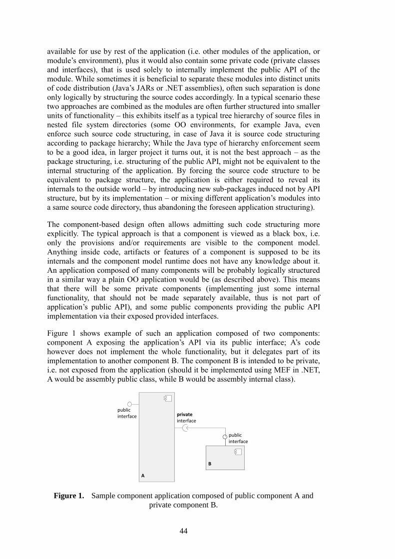
44
available for use by rest of the application (i.e. other modules of the application, or
module’s environment), plus it would also contain some private code (private classes
and interfaces), that is used solely to internally implement the public API of the
module. While sometimes it is beneficial to separate these modules into distinct units
of code distribution (Java’s JARs or .NET assemblies), often such separation is done
only logically by structuring the source codes accordingly. In a typical scenario these
two approaches are combined as the modules are often further structured into smaller
units of functionality – this exhibits itself as a typical tree hierarchy of source files in
nested file system directories (some OO environments, for example Java, even
enforce such source code structuring, in case of Java it is source code structuring
according to package hierarchy; While the Java type of hierarchy enforcement seem
to be a good idea, in larger project it turns out, it is not the best approach – as the
package structuring, i.e. structuring of the public API, might not be equivalent to the
internal structuring of the application. By forcing the source code structure to be
equivalent to package structure, the application is either required to reveal its
internals to the outside world – by introducing new sub-packages induced not by API
structure, but by its implementation – or mixing different application’s modules into
a same source code directory, thus abandoning the foreseen application structuring).
The component-based design often allows admitting such code structuring more
explicitly. The typical approach is that a component is viewed as a black box, i.e.
only the provisions and/or requirements are visible to the component model.
Anything inside code, artifacts or features of a component is supposed to be its
internals and the component model runtime does not have any knowledge about it.
An application composed of many components will be probably logically structured
in a similar way a plain OO application would be (as described above). This means
that there will be some private components (implementing just some internal
functionality, that should not be made separately available, thus is not part of
application’s public API), and some public components providing the public API
implementation via their exposed provided interfaces.
Figure 1 shows example of such an application composed of two components:
component A exposing the application’s API via its public interface; A’s code
however does not implement the whole functionality, but it delegates part of its
implementation to another component B. The component B is intended to be private,
i.e. not exposed from the application (should it be implemented using MEF in .NET,
A would be assembly public class, while B would be assembly internal class).
publicinterface private
interface
B
publicinterface
A
B
publicinterface
Figure 1. Sample component application composed of public component A and
private component B.
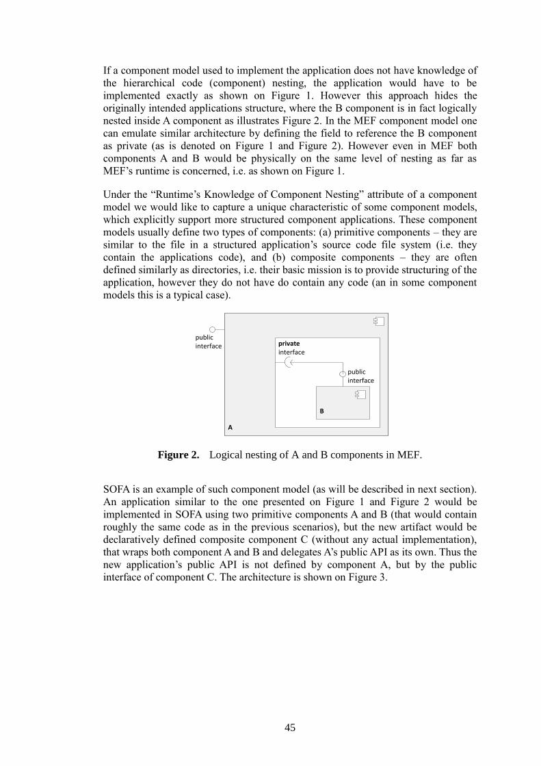
45
If a component model used to implement the application does not have knowledge of
the hierarchical code (component) nesting, the application would have to be
implemented exactly as shown on Figure 1. However this approach hides the
originally intended applications structure, where the B component is in fact logically
nested inside A component as illustrates Figure 2. In the MEF component model one
can emulate similar architecture by defining the field to reference the B component
as private (as is denoted on Figure 1 and Figure 2). However even in MEF both
components A and B would be physically on the same level of nesting as far as
MEF’s runtime is concerned, i.e. as shown on Figure 1.
Under the “Runtime’s Knowledge of Component Nesting” attribute of a component
model we would like to capture a unique characteristic of some component models,
which explicitly support more structured component applications. These component
models usually define two types of components: (a) primitive components – they are
similar to the file in a structured application’s source code file system (i.e. they
contain the applications code), and (b) composite components – they are often
defined similarly as directories, i.e. their basic mission is to provide structuring of the
application, however they do not have do contain any code (an in some component
models this is a typical case).
A
publicinterface private
interface
B
publicinterface
A
privateinterface
B
publicinterface
Figure 2. Logical nesting of A and B components in MEF.
SOFA is an example of such component model (as will be described in next section).
An application similar to the one presented on Figure 1 and Figure 2 would be
implemented in SOFA using two primitive components A and B (that would contain
roughly the same code as in the previous scenarios), but the new artifact would be
declaratively defined composite component C (without any actual implementation),
that wraps both component A and B and delegates A’s public API as its own. Thus the
new application’s public API is not defined by component A, but by the public
interface of component C. The architecture is shown on Figure 3.
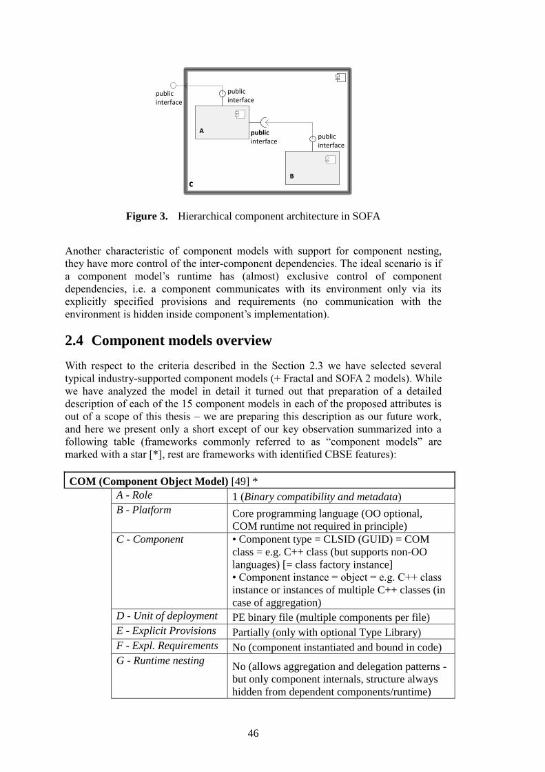
46
CB
publicinterface
A
publicinterface
publicinterface
CB
publicinterface
A
publicinterface
publicinterface
publicinterface
Figure 3. Hierarchical component architecture in SOFA
Another characteristic of component models with support for component nesting,
they have more control of the inter-component dependencies. The ideal scenario is if
a component model’s runtime has (almost) exclusive control of component
dependencies, i.e. a component communicates with its environment only via its
explicitly specified provisions and requirements (no communication with the
environment is hidden inside component’s implementation).
2.4 Component models overview
With respect to the criteria described in the Section 2.3 we have selected several
typical industry-supported component models (+ Fractal and SOFA 2 models). While
we have analyzed the model in detail it turned out that preparation of a detailed
description of each of the 15 component models in each of the proposed attributes is
out of a scope of this thesis – we are preparing this description as our future work,
and here we present only a short except of our key observation summarized into a
following table (frameworks commonly referred to as “component models” are
marked with a star [*], rest are frameworks with identified CBSE features):
COM (Component Object Model) [49] *
A - Role 1 (Binary compatibility and metadata)
B - Platform Core programming language (OO optional,
COM runtime not required in principle)
C - Component • Component type = CLSID (GUID) = COM
class = e.g. C++ class (but supports non-OO
languages) [= class factory instance]
• Component instance = object = e.g. C++ class
instance or instances of multiple C++ classes (in
case of aggregation)
D - Unit of deployment PE binary file (multiple components per file)
E - Explicit Provisions Partially (only with optional Type Library)
F - Expl. Requirements No (component instantiated and bound in code)
G - Runtime nesting No (allows aggregation and delegation patterns -
but only component internals, structure always
hidden from dependent components/runtime)
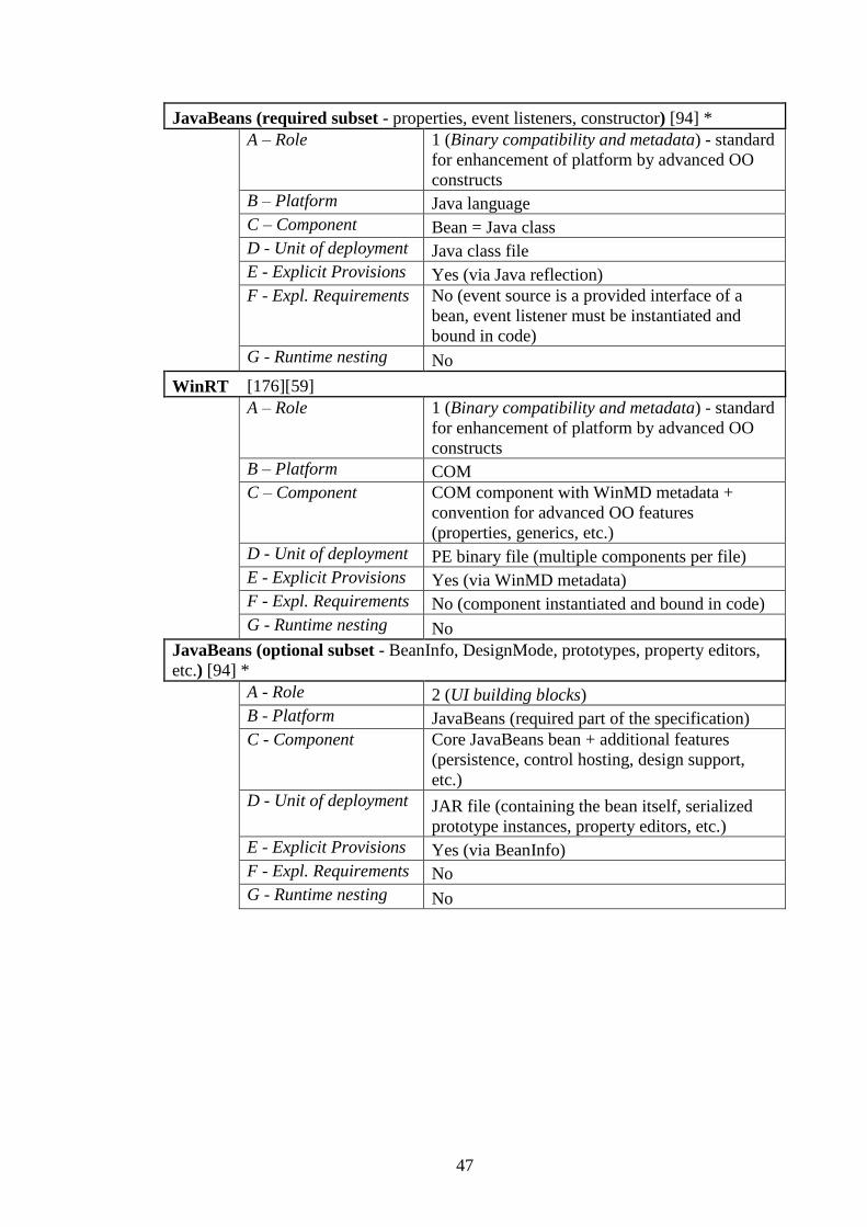
47
JavaBeans (required subset - properties, event listeners, constructor) [94] *
A – Role 1 (Binary compatibility and metadata) - standard
for enhancement of platform by advanced OO
constructs
B – Platform Java language
C – Component Bean = Java class
D - Unit of deployment Java class file
E - Explicit Provisions Yes (via Java reflection)
F - Expl. Requirements No (event source is a provided interface of a
bean, event listener must be instantiated and
bound in code)
G - Runtime nesting No
WinRT [176][59]
A – Role 1 (Binary compatibility and metadata) - standard
for enhancement of platform by advanced OO
constructs
B – Platform COM
C – Component COM component with WinMD metadata +
convention for advanced OO features
(properties, generics, etc.)
D - Unit of deployment PE binary file (multiple components per file)
E - Explicit Provisions Yes (via WinMD metadata)
F - Expl. Requirements No (component instantiated and bound in code)
G - Runtime nesting No
JavaBeans (optional subset - BeanInfo, DesignMode, prototypes, property editors,
etc.) [94] *
A - Role 2 (UI building blocks)
B - Platform JavaBeans (required part of the specification)
C - Component Core JavaBeans bean + additional features
(persistence, control hosting, design support,
etc.)
D - Unit of deployment JAR file (containing the bean itself, serialized
prototype instances, property editors, etc.)
E - Explicit Provisions Yes (via BeanInfo)
F - Expl. Requirements No
G - Runtime nesting No

48
.NET components [128]
A – Role 2 (UI building blocks)
B – Platform .NET platform (CLR)
C - Component • .NET class implementing IComponent
interface
• IComponent provides only support for hosting
the class instance (reference to ISite interface) +
information about design mode
D - Unit of deployment .NET assembly (multiple components per
assembly)
E - Explicit Provisions Yes (via .NET reflection)
F - Expl. Requirements No (component instantiated and bound in code)
G - Runtime nesting No
ActiveX [129]
A – Role 2 (UI building blocks)
B – Platform COM
C - Component ActiveX control = COM component
implementing recommended interfaces
(persistence, late dispatch, control hosting,
design support, etc.)
D - Unit of deployment COM component (usually single component per
PE binary file with .ocx extension)
E - Explicit Provisions Partially (optional Type Library or
IProvideClassInfo interface)
F - Expl. Requirements No (component instantiated and bound in code)
G - Runtime nesting No
.NET assemblies [63][89] *
A – Role 3 (Support for versioning and deployment)
B – Platform .NET's CLR execution engine (EE)
C – Component .NET assembly (main PE binary file + manifest
+ optional additional files) = strong name
D - Unit of deployment .NET assembly (usually single PE binary file,
but multifile assemblies are also possible)
E - Explicit Provisions Yes (via .NET reflection)
F - Expl. Requirements Partialy (only assembly without contract)
G - Runtime nesting No
OSGi (Open Services Gateway initiative) [139] *
A – Role 3 (Support for versioning and deployment)
B - Platform Java plaform (JVM)
C - Component Bundle = JAR file + metadata (manifest)
D - Unit of deployment Bundle
E - Explicit Provisions Yes
F - Expl. Requirements Partially (only bundle without contract)
G - Runtime nesting No
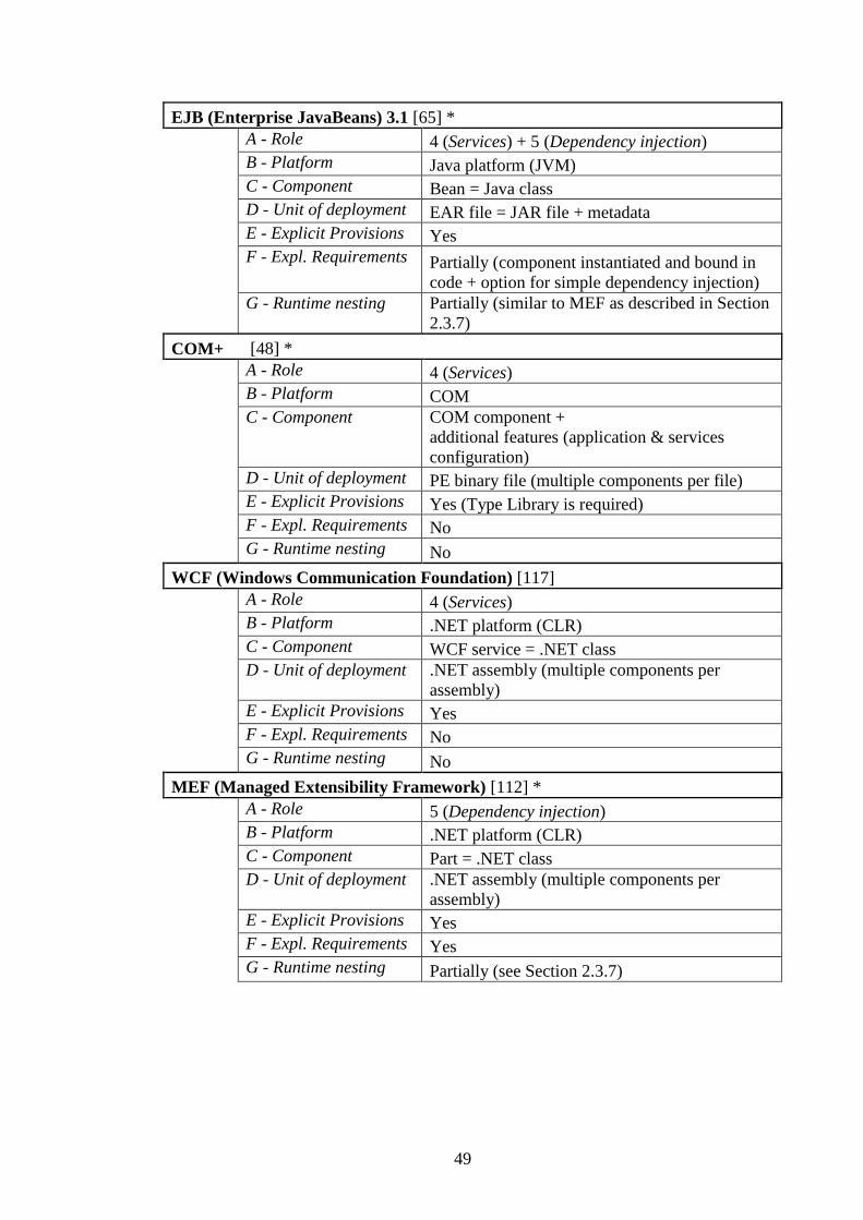
49
EJB (Enterprise JavaBeans) 3.1 [65] *
A - Role 4 (Services) + 5 (Dependency injection)
B - Platform Java platform (JVM)
C - Component Bean = Java class
D - Unit of deployment EAR file = JAR file + metadata
E - Explicit Provisions Yes
F - Expl. Requirements Partially (component instantiated and bound in
code + option for simple dependency injection)
G - Runtime nesting Partially (similar to MEF as described in Section
2.3.7)
COM+ [48] *
A - Role 4 (Services)
B - Platform COM
C - Component COM component +
additional features (application & services
configuration)
D - Unit of deployment PE binary file (multiple components per file)
E - Explicit Provisions Yes (Type Library is required)
F - Expl. Requirements No
G - Runtime nesting No
WCF (Windows Communication Foundation) [117]
A - Role 4 (Services)
B - Platform .NET platform (CLR)
C - Component WCF service = .NET class
D - Unit of deployment .NET assembly (multiple components per
assembly)
E - Explicit Provisions Yes
F - Expl. Requirements No
G - Runtime nesting No
MEF (Managed Extensibility Framework) [112] *
A - Role 5 (Dependency injection)
B - Platform .NET platform (CLR)
C - Component Part = .NET class
D - Unit of deployment .NET assembly (multiple components per
assembly)
E - Explicit Provisions Yes
F - Expl. Requirements Yes
G - Runtime nesting Partially (see Section 2.3.7)

50
Spring [163][164]
A – Role 5 (Dependency injection) + 4 (Services)
B – Platform Java (JVM) or .NET (CLR) platforms
C - Component Bean = Java class/.NET class
D - Unit of deployment Java class file/.NET assembly (multiple
components per assembly)
E - Explicit Provisions Yes
F - Expl. Requirements Yes
G - Runtime nesting No
Fractal [35][27][3] *
A – Role 6 (Unit of architectural nesting and composition)
+
5 (Dependency injection)
B – Platform Java platform (JVM)
C - Component • Primitive component = Java class,
• Composite component = architectural unit
(Fractal runtime entity)
D - Unit of deployment Component
E - Explicit Provisions Yes
F - Expl. Requirements Yes
G - Runtime nesting Yes
SOFA 2 [40] *
A – Role 6 (Unit of architectural nesting and composition)
+
5 (Dependency injection)
B – Platform Java platform (JVM) - (or similar OO language
platform)
C - Component • Primitive component = Java class,
• Composite component = architectural unit
(SOFA runtime entity)
D - Unit of deployment Component
E - Explicit Provisions Yes
F - Expl. Requirements Yes
G - Runtime nesting Yes
2.5 Lessons Learnt from Analyzing the Selected
Component Models
Ability to combine multiple component models is not limited to having disjoint set of
attributes of the participating component models – easiest way to see it is on the
support for explicit provisions attribute: as most of the model support this feature,
combining two of them will lead to “conflicting” set of provisions. However if look
at the problem from a wider perspective (not restricting our view on the single
attribute only), we will discover no conflict occurs in reality – if both component
51
models assume a different role of a component, thus themselves being on different
levels of abstraction, each of them will define its own component provisions for each
respective level of abstraction. The combination of “conflicting” attributes is then
similarly possible as is the combination of two different component models.
Furthermore two component models can be combinable even if they both define a
same or similar role of a component. Compatibility of such models then depends on
deeper analysis of respective features and their implementation of the two models.
An example is the WinRT component model that falls into a same category
according to the role of a component attribute as the COM component model.
However as the WinRT is designed to enhance the COM features and uses the COM
component model as part of its underlying platform, the two models are not only
combinable, but the WinRT component model cannot be used without COM.
Related to services interpretation there was a very interesting discussion among
participants of FESCA 2007 [70] workshop. Ralf Reussner initiated a quite deep and
long dispute on what is a relationship between components and services. The final
result the community came up with was a statement that: “Services are defined on a
different level of abstraction than components. A service can be implemented using
one of the component technologies. And if so, a service is than equivalent to a
deployed component (instance)”. While this seems to define services and
components as two very distinct concepts, the statement is in fact coherent with our
view on services and the conclusions presented. If we look at services as specific
type of components, then according to our conclusion, one can choose another
component model not in conflict with the “service” component model and create an
application utilizing both of them. The “service” components will then provide the
“service” features for the application, while the underlying components provide some
other lower level features (e.g. dependency injection). The components from the
lower component model will then be the “deployed components” from the FESCA
statement. These components will then in turn use some features of the upper
“service” component model that will allow them exhibit service oriented aspects.
Example of such connection can be development of an enterprise application taking
benefits of both EJB and Spring technologies – the EJB being the upper “service”
component model, and the Spring being the lower component model serving as a
dependency injection container – i.e. an example EJB bean (EJB components) could
be composed of several Spring beans (Spring components) via dependency injection.
2.6 Problem Statement Revisited
Although there are many hierarchical component models (we presented the Fractal
and SOFA representatives), to the best of our knowledge none of them is used in
regular software development by a wide community of developers nor is
acknowledged by the industry. At the first glance this situation seems puzzling as the
hierarchical component models are of the farthest CBSE modeling approaches
currently existing. Thus if we take a premise that CBSE should bring advantages
over the classical OO programming techniques and common monolithic software
design principles, the hierarchical component models should bring most advantages
to the CBSE field.

52
For example, when trying to understand the advantages of the Fractal component
model, one would typically look at the project’s web site first – to cite from two
available project overviews at Fractal’s project page [72]:
Fractal is a modular and extensible component model that can be used
with various programming languages to design, implement, deploy and
reconfigure various systems and applications, from operating systems to
middleware platforms and to graphical user interfaces.
and
The Fractal component model heavily uses the separation of concerns
design principle. The idea of this principle is to separate into distinct
pieces of code or runtime entities the various concerns or aspects of an
application: implementing the service provided by the application, but
also making the application configurable, secure, available, etc. In
particular, the Fractal component model uses three specific cases of the
separation of concerns principle: namely separation of interface and
implementation, component oriented programming, and inversion of
control.
The description is clearly feature oriented, i.e. it is trying to sell the most interesting
and important features of the Fractal component model. There are also many Fractal
or its Julia implementation related papers. Among them the original defining one
[36] presents a thorough list of requirement on a component model as viewed by the
authors. However the text is more oriented to again give a good understanding of
Fractal component model features and to analyze their relationship to other existing
component models and their features. The other key papers describing the
implementability of Fractal in Java programming language [34][35] are then purely
oriented to give readers introduction into the advanced concepts implemented. The
most recent paper summarizing up-to-date state of the Fractal ecosystem [27]
provides a nice overview of Fractal, but is written mostly with respect to the
interesting feature set. While there are papers trying to put Fractal into a real life
context (e.g. an extension of Fractal to allow seamless implementation of grid
oriented applications [22]), papers describing the background goals the authors had
in mind when designing Fractal are missing.
The SOFA 2 component model as complex as it is, has a similar problem as the
overview on its web site or contents of summary papers are also oriented towards the
features SOFA provides.
As many of the features of both Fractal and SOFA component model are quite
complex and unorthodox (one of them is even the simple notion of component
nesting into hierarchical architectures), the general lack of clear statements about
component model goals and clear visions of how and where the provided features
can be beneficial can be the key problem behind the low penetration of these
component models into wider developer community. If we look at the component
models presented in thesis, we can see a common pattern of all of the industrial
component models falling into categories/roles (1) to (5) as defined in Section 2.3.1,
and none of them being of the hierarchical nature. While it is hard to distinguish a
cause and a consequence – i.e. whether the industrial component models have clearly
53
stated goals and whether they target specific developer needs because they are driven
by a professional software company, that needs the solution; or whether the clear
goals led to the wide adoption and later to adoption in the industry as well – it
appears to be clear that a lack of well-defined goals or desired properties and some
common case studies illustrating the key advantages of hierarchical component
models is one of the common and key reasons for the low adoption. Simply said, the
potential users of hierarchical component models just do not understand their key
features due to their inherent complexity, and thus are not able to foresee the
advantages they are able to deliver them.
2.7 Revised Goals of the Thesis
With respect to the current state-of-the-art in CBSE as analyzed in Section 2.1,
Section 2.2 and Section 2.3 and the problems presented in previous Section 2.6 the
goals of the thesis should be revised to closely reflect the current CBSE problems
that we feel a necessary to solve. The goals are:
(1) To identify the desired properties the hierarchical component models should
expose in order to support wide use in software industry. We will provide
examples of two industrial domains, where applying the hierarchical
component models can be most beneficial.
(2) To evaluate hierarchical component models in two major case-studies and
present problems encountered.
(3) To provide a novel contribution partially solving the problems identified
while addressing the goal (2): approach to deal with complex error traces,
support for modeling dynamic changes in hierarchical component
architectures, and specification language for modeling component
environment behavior.
54
Chapter 3
Hierarchical Component Models Coming to Rescue –
Identifying Benefits and Key Problems
This chapter is structured according to the revised goals presented in Section 2.7. In
Section 3.1 we identify and present the key areas where we see hierarchical
component models most advantageous and propose their desired properties, whereas
in Section 3.2 we provide an overview and summary of the published results. The
latter section and the rest of the thesis are ordered again according to the goals
presented. First we present two case studies to evaluate advantages and
disadvantages of hierarchical components models (they are presented as a verbatim
copy of parts of CRE project manual [3] and two of the published papers/book
chapters [96][38]). In Section 3.2 we further present a summary of the key problem
identified when modeling the case studies using a hierarchical component model –
modeling an application with dynamic nature of its potential components and
modeling the components environment behavior to allow its behavior verification
without the whole application being completed – this presents summary of the
remaining two papers coping with these problems [42][113].
3.1 Target Domain of Hierarchical Component Models
This section forms our response to the first of the revised goals of the thesis, i.e. we
analyze the concepts available in hierarchical component models and show their key
advantages.
3.1.1 Hierarchical Component Models from Program Correctness
Verification Perspective
During many of our projects (e.g. CRE project presented in Chapter 5, and CoCoME
presented in Chapter 6) we gained a lot of experience with component based
software engineering. While CBSE can be viewed from many different angles and
covers many software engineering aspects (as presented in Chapter 1 and Chapter 2),
our main focus lies in the domain of software correctness verification and
performance prediction (which is unfortunately a very complex problem by itself and
as such it is out of the scope of this thesis). An ability to apply some correctness
verification techniques to component-based applications is a crucial feature we
require to be present in any component-oriented modeling and/or development
approach. Being this of our top priority, let us show advantages of hierarchical
component models in the domain of software correctness verification first.
During development of component-based applications two common approaches are
usually taken: (1) the whole application code base is created from scratch and a
CBSE approach is used to enhance application maintainability and extensibility, (2)
there exists a repository of existing components (while it is common to think about a
public component repository or a component store in this context, see [165], a private
55
repository of in-house developed components is also a valid case for the presented
scenario), and the target application is “developed” just by selecting right set of
components and interconnecting them accordingly (so called Commercially available
Off-The-Shelf or COTS approach applied on software components – see [173]; for a
more recent analysis of the idea see Chapter 15 in [53]). These two approaches are in
fact very extreme cases of a real development process. On the one hand, it is virtually
impossible to create a new application just from purely pre-implemented
components, as at least some glue or transformation code is required in non-
theoretical cases. Furthermore the probability of having all the required components
somewhere in a repository and at the same time not having an application with
required features combining the components is fairly low. On the other hand in a
typical situation with a constrained budget and deadlines, developers try to reuse as
much code as possible, and do not try to develop everything from scratch. So a
common scenario in component-based application development would be a
combination of (1) and (2).
In any case, the number of software components (whether newly developed or reused
from some repository) can grow quite high, and it becomes a key problem to keep
the whole application in a coherent state. The problem can even worsen if different
components are developed by different developers or developer teams (this is
inherently highly probable in case of components pulled from a repository of existing
components). While initially it might seem the problem is easily solvable just by
features of common programming environments – i.e. that it is sufficient just to
verify compatibility of components based on syntactic compatibility of each other
interfaces – it is generally not true. Each method implicitly assumes some
preconditions are holding before its call, and the component itself usually maintains a
set of invariants that have to hold for it to work properly.
In our approach of behavior protocols (see Chapter 4) we cope with this problem by
specifying all possible correct behaviors of a component by a behavior protocol (a
combination of valid method calls on a component and all variations of responses the
component can exhibit as a reaction to a sequence of method calls). For each of the
components considered to be used in an application we have to have a single
behavior protocol describing all the possible traces of incoming and outgoing calls
on that component exhibiting component’s correct behavior (none of the
preconditions and invariants of the component are broken). As in a typical
application the components are not directly communicating only with their adjacent
neighbors, but via them they are logically communicating also with the others (the
rest), for a verification of a correct incorporation of a component we need to verify
the composition as a whole (e.g. a component A might be so general, that a
component B is not compatible with it [A exhibits some behavior the B is not able to
accept); but adding a component C into the composition [connected just to the A
component directly] might constrain the A’s behavior in a way it becomes
compatible with component B). This then leads to a need to model the state space of
the whole application at once, which in turn leads an exponential growth in number
of states (so called state space explosion problem – see Chapter 4) – which is roughly
a Cartesian product of the state spaces of individual components.
Thus lowering a number of components needed in a single verification step would
decrease the problem complexity in an order of magnitude. Such a simplification is
natural result of hierarchical structuring of software components. With an application
56
modeled as a set of nested composite components, each of them being potentially
composed of either primitive components (leafs of the hierarchy) or further nested
composite components, the verification problem scales well by falling apart to
smaller sub-problems. Now we have a behavior protocol for each of the primitive
components (as in the original scenario of a flat model with all components on a
single level of nesting), and add new behavior protocols for each of the new
composite components. A behavior protocol for a composite component will
describe only the expected behavior of the whole component (exhibited by its inner
components), that is observable from the outside. With all this information, the
verification then can be done step by step, i.e. for each composite component a
composition of (behavior protocols) its subcomponents is verified against its own
expected behavior to the outside world (composite component’s behavior protocol).
When modeling the CRE case-study (see Chapter 5 for more details) we started with
an initial simple model of several components and created behavior protocols
describing their behavior. However after trying to verify correctness of their
composition we ran into a dead end, as the all the possible interleavings of their
behavior was simply too complex and we were not able to finish the verification in a
reasonable time (in no more than a few hours). As a next step we naturally separated
the applications components into subsets according to their functionality and created
respective composite components encompassing the subsets behavior. It turn out this
was a clear step that we should have done already during the original modeling of the
application. Not only it would better allow us to reuse the composite components
(behavior groups) in another projects, but more importantly, the problem of
composition correctness verification shrunk at each level of nesting that much, that
we were able to verify each of the smaller compositions in matter of hours (we had to
verify correctness of composition inside each of the new composite components at
each level of nesting, one by one). This final application architecture is the one
presented in Chapter 5 and in Appendix A.
3.1.2 Hierarchical vs. Flat Component Architectures at Runtime –
A General View
An important aspect has not been analyzed in detail yet – do we need the hierarchical
component view both at the design time and at runtime? From the perspective of
basic formal verification of the program correctness the answer seems quite
straightforward – the model being the program’s abstraction seems to be the most
important part by itself (or more precisely its structure – i.e. its hierarchical
composition). A property verification tool can analyze the model and effectively
decide if the required properties are satisfied by the model or not. The next step, i.e.
the verification of the compliance of the actual program’s code to the model
specification, would be typically done piece by piece – component by component
(similar to some other static verification techniques – e.g. .NET Code Contracts
Static Verifier verifying the preconditions and postconditions on method-by-method
basis). The system would take each of the primitive components and verify whether
their implementation complies with the appropriate portion of the model (primitive
component behavior specification). And for this system to work it is not necessary,
that the actual runtime components (as constituted by the implementation – e.g.
actual Java class implementing the component) are still organized in a hierarchical
manner – i.e. the system can be flattened.
57
A simplest approach to the flattening is to retain all the primitive components in the
system and just erase the composite components – nonetheless all the bindings
between the components will be retained as well. As a path formed by typical follow-
up of bindings in a hierarchical component architecture begins and ends at primitive
components (e.g. A and B), during the flattening process these two components are
just bound together directly (direct binding between A and B).
A clear advantage of such approach is that the target system does not have to have
any support for the component oriented code at all – i.e. no special component
system runtime is needed and the application can be deployed to any regular software
platform or software application framework without any need of special
configuration. This is very advantageous in many common scenarios as it is
minimizing external code dependencies – so the installation and distribution of the
application is simplified (as a lot of complex component systems required
complicated installation and configuration process which is often in contradiction to
the more and more promoted XCOPY style installation experience on desktop/end-
user oriented platforms), or it can even enable using the componentized application
code in situations unrealizable with common component systems (typical example is
embedding the code into a more complex software system – e.g. using it as a sort of a
plug-in or user-definable extension – as such systems typically define their own
programming model and code distribution and localization inherently incompatible
with a component system implementation).
An interesting component system in this context is the MEF component model – as
described in Section 2.3.7 and 2.4 – MEF can be considered to be somewhere
halfway in between hierarchical and flat component models. The architecture as
described by a MEF initialization code can be hierarchical in general, however such
multilevel structure is only used during the component description phase and for
component look-up and instantiation, but during the “composition” process the actual
class instances implementing the available components are interconnected directly
with each other – i.e. the flattening occurs at runtime during the last step of
component architecture creation. This behavior allows developers to use the MEF in
most .NET-based software development scenarios, as the MEF typically does not
interfere with any other development paradigm required by the developer at the same
time (in a same application).
In component models more oriented on the architecture’s hierarchy, e.g. Fractal and
SOFA 2, the flattening can be a bit more complex process. While composite
components in this case often do not encompass any business code, they often
contain a lot of application control features (e.g. life cycle controllers, interceptor and
aspect waving infrastructure, implementation of other non-functional properties) that
have to be somehow present in the final application’s code as well (so the
applications behavior reflects all the features and properties induced by the
application model or architecture design). This typically leads to generation of pieces
of “glue” code during the flattening that will reside in the final executable along the
code of all the primitive components. The glue code can be for example generated
from connector description capturing the non-functional properties, see [43].
To sum up the flat component representation at runtime seems to be rather
straightforward approach without any disadvantages. While this might be true during
58
development of a typical desktop application, this observation does not hold in other
more specialized scenarios as will be shown in the following Section 3.1.3.
3.1.3 Importance of Hierarchical Runtime Architectures in
Industrial Scenarios
During our research in the component oriented software domain we have participated
in several international projects with industrial partners involved. Aside from
focusing on delivering the required results of the individual projects, we also
intensively tried to listen to all the industrial partners’ needs and to gather as much of
their experience as possible. Although companies do not always use component
technology directly, they do often use similar concepts or are searching for new
approaches to software development in directions, where the component oriented
software design can be of a huge advantage. The following text presents our
apprehension of needs two typical examples (ABB and ESA) relevant to the context
of this thesis.
ABB
ABB is a large international corporation developing and selling many products and
providing services in a broad spectrum of domains. In context of this thesis its
German branch [1] and its German research and development center are particularly
interesting as one of their target domains is development of control and monitoring
systems for large industrial plants (ranging from gas-processing and chemical plants
to wide range of power plants including nuclear power plants). When a new plant is
built and an ABB control system is installed, it is expected to be in service for
several decades. And for the types of plants mentioned the only admissible scenario
is, that after the plant begins its regular operations, the owning company cannot
afford some long lasting outages in the services provided by the plant. This implies
that the control and monitoring system has to run without interruption or shut down
for mostly the whole life-span of the plant where it has been deployed. However
during such a long uptime (of several decades) the system definitely needs some
maintenance, in context of the deployed software it naturally means deployment of
new versions of the software (whether to correct any bugs or inconsistencies, should
any be found, but mostly to shape it according to the changing needs in evolving
production processes of the plant).
Hierarchical component models/systems can bring a nice solution to this problem. If
the system is modeled, designed and implemented correctly in agreement with ideal
practices of designing hierarchically composed component application, the units of
functionality would be separated in specific composite components. And if the
component system runtime is aware of the hierarchy and force the code to obey the
rules of nesting, the runtime has full information about the applications architecture
and can take the liberty of exchanging the whole composite component (including its
internals – i.e. the components nested in lower levels of component hierarchy) with
its new version with corrected or enhanced functionality. With the fully known
architecture of the system the task is much more simpler as in a general scenario of a
unconstrained application not incorporating the concepts of hierarchical component
models – in the earlier case the hierarchical component system runtime has “just” to
monitor the components interfaces in question and pause all incoming and outgoing
communications and in this window update the component and later resume the
59
communication by letting the retained flow of messages (method calls) to be passed
to the new version of the component. The whole process can be done on a live
system without a need to stop any other components that are not participating in the
update. While the process is not exactly that simple as described above, the
hierarchical component models are in a unique position to support such advanced
scenarios – an example our experience with a successful prototype implementation of
a similar approach proving the idea is feasible in context of hierarchical component
models (namely the SOFA 2 component model) can be found in [152].
Enhancing the common hierarchical component models concepts with a new concept
of dynamic entities, that we have proposed in [41], [42], and later in Chapter 7, can
further simplify the problem and would allow the implementation to be more general
by supporting a wider range of application design approaches. The dynamic entities
formalize a typical externally visible subset of components state (namely allows to
identify and pass references to internally allocated resources) and allow to extend the
component model’s runtime knowledge about the applications structure. Revealing
such knowledge to the runtime then enables to more easily and directly implement
the component exchange as described above even for more complex components that
do not have their state idealistically encapsulated inside, but share part of the state
with other components in the system (even on higher levels of nesting).
Another challenge lay especially in emerging directions the ABB tries to apply in the
context of human interfaces to the control and monitoring system it is developing.
Traditionally the systems are managed both from a centralized control center and
from local terminals located near the actual devices and facilities all around the plant.
These local terminals are used to control any locally specific properties of the device
and to provide many diagnostic and maintenance indicators and control options.
However with the advent of highly computationally and graphically capable devices
as smart mobile phones and smart tablets ABB is introducing an interesting paradigm
shift in the area mentioned (among other reasons, this change is also backed up by
demand of young employee generation, that is becoming a majority in many
industrial plant world-wide, to use the systems they are used to and to control the
industrial devices in a similar manner they are used to from their personal lives) – a
prototype future plant employee is envisioned to have its personal smart phone
and/or tablet and to be able to go thought the plant freely during his or hers shift, and
control and monitor the devices remotely without need to use any specific local
terminals. Furthermore he or she should not be constrained to a single plant, but he or
she should be able to migrate between multiple plants of a company, even during a
single shift. And the different plants (of even a same company) would most probably
not be exactly the same (having different devices or different models of a same
device for one functionality required, similar devices configured or deployed with a
different sets of capabilities) – in context of software systems, this means the control
system must be highly configurable to support different devices and different
versions of the control subsystems (each plant might use a different version of a
system).
Again the hierarchical component model can provide advantages in this context. The
clear structuring of the application’s architecture allows easy extensibility of the
control system. Our positive experience on the subject is for example reflected in
[142], that presents an implementation of component packaging and distribution
system in context of SOFA 2 component system, which takes advantage of SOFA’s

60
hierarchical nature. Similar approach in cooperation with the one mentioned [152]
can be used to implement a highly dynamic control system for a prototype future
plant as described in previous paragraph. If the potential employee would come near
a device of the plant, the component system can automatically download new control
component in a correct version from the device and install it into the component
system instance on the employees mobile device.
ESA
The European Space Agency (ESA) is an organization uniting several of the EU
member states with the goal to cooperate and bring complex space missions to life.
ESA covers effort of a lot of small companies as well as large international
corporations and provides coordination for successful outcome of its own project
proposals. The area covered by ESA missions is much diversified from regular Earth
orbiting satellites, a cargo ship serving the International Space Station to missions
studying several bodies in our solar system (from Mars to Titan), to the actual on
orbit delivery vehicles. A typical long term space mission incorporates a space craft
of any kind (including both mentioned satellites and missions to other planets) takes
currently a lot of preparation spreading several years or even a decade. An interesting
observation is that in most of the missions the whole spacecraft including all core
and payload hardware and software is made from scratch. And ESA is aware that this
is one of the main reasons for such a long time of a mission preparation – which not
acceptable in a long term view as (a) cost of such missions is becoming increasingly
large, (b) if a new interesting goal for space exploration is proposed the actual
science results will be delayed many years or decades (as after the spacecraft launch
the mission duration itself can span several years), (c) as the selection of
technologies used in the mission has to be frozen in quite early phases of the
spacecraft development (this applies to both hardware and software), the spacecraft
is typically very outdated at the time of the actual launch. Taking all there problems
into account ESA’s long term goal is to fundamentally shorten the mission
preparation time from years to month (to a least one year, or in some more optimistic
scenarios even to about three months).
All of these goals has been summarized and applied in an ongoing ESA initiative
SAVOIR (initiated as conclusions of [12], with state current report in [68]), which
has main goal of creating a common base platform for development of on-board
avionics. The initiative is formulated with the specifics of space bound missions in
context of ESA projects in mind. There has been a lot of discussion on many ESA
organized workshops on this topic and as a result and as one of the parts of the
SAVOIR is a goal to prepare component-oriented software architecture to cope with
the problems described above and in SAVOIR. Several approaches were proposed,
among them is the proposal of a component framework [150][84] based on typical
CBSE concepts. Currently the main project established to fulfill the SAVOIR goals
is the CORDET [67] project.
The advantages of the core component orientation aspects are clear and especially
aim at solving the problem of software and hardware reuse, which is minimal in
current approach to development of space crafts in ESA related projects (as
described above). The software reuse, i.e. reusing a same piece of software – a
software component – in multiple missions, is direct implication of a strict
componentization of system software architecture. The hardware reuse (in a single

61
space craft) is an implication of not only the emergence of isolated components in
the architecture, but the typical approach on designing component system’s runtime
for more advanced component models – i.e. if the runtime is given an exclusive
control of the system’s architecture evolvement and of inter-component
communication, the components are bound by the component model’s rules.
Multiple components, that would originally each require its own on-board computer
(this need for component separation typically arises from a need to separate different
payloads or to separate the payload from the mission control), can be in such system
allowed to run simultaneously on a single computer. This change significantly lowers
the overall cost of on-board avionics by greatly reducing the amount of needed
hardware (by its aforementioned reuse). Note that the hierarchical component models
typically exhibit such a tight control of components and their life time.
Another specifics of space exploration missions is the typical requirement of multiple
modes of operation as different on-board hardware is used during different phases of
the mission – this is true especially for more complex solar system covering missions
(i.e. vehicle delivery to the initial orbit, from Earth orbit to target body transition,
target zone [orbit] entering, the actual science mission, optional return to Earth, etc.).
Such missions often include large spacecraft’s hardware reconfigurations – e.g.
physically releasing/dumping some components not necessary for the rest of the
mission, or separation of science modules from the mother space craft (in a list of
ESA missions we can find example of the Huygens lander separation from the
Cassini probe [134]). The ability of hierarchical component models to easily support
smooth system architecture reconfigurations was described above and was also
discussed in this context in our previous work [95]. Moreover our experience is also
reflected in a specific approach to take advantage of hierarchical component models
and to handle directly the different modes of operation of systems componentized
into hierarchical components has been developed in [141]. The original idea is
further expanded in [140] and [148].
3.1.4 Putting All Together – Formal Behavior Specification as an
Advantage
Applying the CBSE concepts in regular software development unfortunately also
introduces some problems. Several companies that already incorporated CBSE
massively into their development process face the following problem: after several
years of applications development they gathered a repository of several thousands of
software components. Naturally when a new application is to be developed, they
would like to reuse their existing components and at least partially develop the
application just by assembling the pre-developed components together (i.e. a way of
application of the COTS principle [173][53]). However, it is clear they have only the
specification of the required behavior of demanded components at the initial stage of
application development, and especially do not have their finalized interfaces ready.
And even if they would, any component already implementing the required behavior
would most probably have at least minor differences in the interface specification
(not to mention, that in most cases the target component in the repository would be
solving a subset or superset of the problem or be an under- or over-abstraction of the
problem). This makes the process of finding the right components a quite challenging
task.
62
It turns out that in a real scenario the size of a repository of components matters, but
with opposite implications than would be naively expected – i.e. the larger the
repository grows, the more useless it is. Even with hundreds of components the
developers cannot browse the repository manually and standard searching
mechanisms fail, as the developers are not only not able to “guess” a correct required
interface declaration, but even a “guess” of a component/interface name or a
reasonable subset of its informal description is impossible (the latter not only due to
inherent creativity of human developers, when it comes to names and textual
descriptions, but often also due to different levels of abstraction used in component
description/name and the search string).
The problem sketched in previous two paragraphs is in fact an extension of the
problem discussed in Section 3.1.1, i.e. a necessity to verify component composition
correctness. Let’s return back to the discussion presented in the section – we argued
that syntactic interface compliance is not enough and to state that two components
are compatible, one has to compare their behaviors on much deeper lever. However
we silently assumed, the components to be composed were already found and
chosen. As we leant later such an assumption is not always possible as it initially
seemed. But should a developer already have a behavioral description for each of the
components in a repository (to verify correctness of their composition in a potential
future system), the same behavioral description can be used to locate the right
component. If the developer prepares a formal description of the expected behavior
for which a component needs to be localized, such description can be used during
search to find a match with formal behavioral description of components existing in
the repository. And should such a “intelligent” repository be implemented, the
hierarchical component models would allow better search results as more abstract
units of code in form of composite components can be also stored in the repository.
The behavioral description of a composite component would only a subset of
functionality of its internal components as constrained by the actual composition of
the composed component – and as such it would be a better abstraction of the
functionality provided by the composite component (as discussed in Section 3.1.1).
As the behavioral description is clear of any internal behaviors not exposed by the
composite component (i.e. its implementation detail), the search in the repository
should be more successful, as the query can only describe the expected behavior and
not an expected implementation (i.e. the developer can state in the query only what a
component should do, and not how it should be done). A similar approach targeting
localization of compatible components as presented above has been described in [31]
Though it was not explicitly stated before, the ability of hierarchical component
models to provide suitable means of component composition correctness (i.e.
absence of some types of bugs, the verification framework targets) would be also a
key feature in context of ABB and ESA projects showcased above. Having the
behavioral description ready for the correctness verification can serve also as a
documentation value as presented in this section. Last of strengths of hierarchical
component models we would like to stress here is a unique position to support
software performance predictability. Since the performance prediction is out of scope
of this thesis as noted in previous chapters, let’s give only a few comments to this
topic. The Palladio Component Model (PCM) [23] is a mature framework for
performance prediction, i.e. for prediction of various QoS related attributes. The
PCM shows nesting software components and creating hierarchical component
architectures brings to the domain of performance prediction similar advantages as it

63
does to the domain of software correctness verification (i.e. structuring of the initial
problem into smaller units on natural boundaries already present in the code and
provision of abstractions for units of code).
The performance prediction approach can be further extended to improve solution to
the component localization problem. If PCM or similar approach is used as a basic to
predict component performance, the Stochastic Performance Logic (SPL) [39] then
can be used to match this performance related description to needs of a developer
that is looking for a right component to solve his or hers problem. A combination of
behavioral description (like behavior protocols) and SPL formulas can be used both
as component specification as well as a search query. Components then can be found
just by specification of their functionality and their QoS attributes (without a need to
exactly require any specific implementation details).
3.1.5 Summary of Hierarchical Component Models’ Desired
Properties
In Section 3.1.1 to Section 3.2.5 we provided a detailed analysis of advantages of
hierarchical component models and shown several domains of software engineering
where these advantages would be especially appreciated. They can be summarized
into the following that can be viewed as the desired properties the hierarchical
component models should target to fully live up to their potential:
(1) Hierarchical component architecture at runtime
(2) Software correctness assurance and verification
(3) Performance prediction
(4) Documentation
3.2 Guide to Published Results – Proposed Solution
Explained
The goal of the rest of the thesis (covering the global revised goals of the thesis as
introduced in Section 2.7), namely Chapter 4 to Chapter 8, is to evaluate the
hierarchical component model’s desired properties (1), (2) and (4) (as defined in
Section 3.1.5) in context of a selected hierarchical component model: Fractal
component model and its Julia implementation – a model with an explicit support for
hierarchical architecture at runtime, a choice that reflects the property (1) from
Section 3.1.5.
The goal of this section is to give the reader a summary of each of the following
chapters (Chapter 4 to Chapter 8) and to give their content into context of remaining
chapters as well as into context of the analysis provided in Chapter 1 and Chapter 2
of the thesis.
Exploring and enhancing hierarchical component models with respect of all four
identified goals can lead to introduction of many very complex problems to solve and
providing a solution to all of them would be out of the scope of this thesis. Instead
we focus only on the problem of verification of the software design and
64
implementation correctness. On the other hand in the case-studies presented later in
the thesis we tried to analyze the project assignments from many different angles in
order to be able to deliver a complex solution that would have positive characteristics
in as many software engineering aspects as possible. A more enhanced case-study
solution in this sense is our CoCoME for Fractal project as described in Chapter 6,
where we were able to provide an architectural model suitable for and used in both
behavioral correctness verification and implementation performance predictions
tasks. A complex approach to solve similar software design and development tasks is
crucial to propose the best approach reasonably applicable in more than one domain.
If the formal method used to provide proofs of application correctness is designed in
isolation without relation to other analyses that might be required to be performed on
the developed application’s code or design, it can lead to a state where the different
analysis methods have contradicting requirements. The same or similar task – e.g.
creation of application’s model – then has to be done multiple times – creating the
similar input separately for each of the analysis methods for example. Such approach
is of course time consuming and can lead to more errors in the models and especially
to model inconsistencies.
In Section 3.1 we identified the key goals of hierarchical component models. As it
seems they should be ideal to model especially the types of applications and to solve
the problems described above, the following Chapters 5 to 7 present our evaluation
of application modeling utilizing all the means provided by componentization into
hierarchically nested components. The following sections (Section 3.2.1, Section
3.2.2, Section 3.2.3, Section 3.2.5, and Section 3.2.6) provide a more detailed
explanation of published results of each respective chapter. Each section is dedicated
to one of the chapters: Chapter 4 (background: behavior protocols), Chapter 5 (CRE
case-study), Chapter 6 (CoCoME case-study), Chapter 7 (capturing entities in
architecture), Chapter 8 (modeling Windows kernel drivers’ environment).
3.2.1 Behavior Protocols and Verification of Software Model
Correctness (Chapter 4)
In Chapter 4 we introduce our approach to verification of application correctness and
provide introduction into its background. First we introduce the behavior protocols
formalism itself – it is a specification language, where each behavior protocol is an
expression that expresses all possible behaviors of a software component (behavior
protocols are especially targeting hierarchical component models). Basic unit of a
behavior protocol is an action expressing an incoming or outgoing method call on a
component boundary (more precisely behavior protocols distinguish more fine
grained events of the call itself and its return back to caller). These method call
actions are then composed with several operators (like sequence, alternative, parallel
execution, etc.) to form a final behavior protocol expression. More details and a
formal explanation can be found in Chapter 4.
In the second half of Chapter 4 we show, how are behavior protocols used to verify
correctness of component based applications. As already mentioned before, we
verify the application correctness by studying the applications architecture and by
verifying it for lack of composition errors. Each component in the architecture
(whether primitive or composite) is assigned a single behavior protocol that describes
its behavior – i.e. acceptable ordering of method calls on that component boundary,
65
that the component is able receive at its provided interfaces and a relationship to and
promise of possibly emitted method calls to required interfaces. We introduce three
methods used to apply behavior protocols in application correctness verification:
(1) Static verification: In this method we verify the applications architecture for
lack of various composition errors. This process is divided into steps, where
in each step a correct composition is verified for a single composite
component and all components directly nested inside of it (i.e. on a minus one
level of nesting – these might be primitive components [directly implemented
in some programming language] or other composite components). This
process verifies the inner components’ composition as constrained by their
enclosing composite component’s behavior protocols. This proves the inner
architecture of a composite component behaves only according to the
composite components behavior protocol and only such behavior is exhibited
to the outside of than component. In next steps this process is repeated for
other composite components in the architecture, considerably on different
levels of nesting. An important note is that the whole application does not
have to be verified always completely, but as the composite components can
be reused in a different application than created for, the same is true for their
behavior protocols forming a “prove” of their functionality (i.e. if a
composition of a composite component is not changes, its composition can be
verified only once).
(2) Runtime verification: This method is a smarter variant of unit tests – it
verifies for primitive components, they are implemented as specified in their
behavior protocol.
(3) Code analysis: This is another variant of verification of primitive component
correctness. Contrary to the runtime verification the code analysis method
does not test the component at runtime, but does an analysis of component
source code to verify the component’s implementation really obeys its
behavior protocols. While this method is more exhaustive and can provide a
better confidence on component’s correctness than runtime verification, it
might not be able to finish for too complex component implementations (due
to the state space explosion problem). The runtime verification then can be
used as a fall back method in such situations.
Whole content of Chapter 4 is a verbatim copy of excerpts from CRE project manual
[3].
3.2.2 CRE Case-study – Enhancing the Fractal Tool-chain with
Correctness Verification Techniques (Chapter 5)
In Chapter 5 we present our experience from the first case-study we have devised
and implemented in one of our projects – the CRE for Fractal. The CRE project
mostly targeted a viable way of verifying a componentized application design and to
provide basic means to verify coherence between resulting application’s
implementation to its original design. Contribution of the project can be divided into
several key areas: design of a case-study demo, behavior protocols and their tool-
chain integration into Julia Fractal implementation, implementing the demo in
Fractal and modeling it in behavior protocols, extensions of behavioral protocols to
66
be able to describe the case-study demo, verification of behavioral correctness, ideas
how to cope with complex error traces possibly resulting from the verification
process. In the following paragraphs we present a summary of the project results
from Chapter 5.
Applying a research concept in real life scenario is not a simple task as it might seem
– as much has to be done to actually and successfully implement a viable idea, often
some enhancements and/or changes are usually required (it was nicely summarized
by team members of Ivana Černá from Masaryk University in Brno: “an algorithm
[sketch] is not a tool – a lot of non-trivial work is necessary to provide a feasible
implementation in a target programming environment [algorithm engineering]”).
The step from an idea to its implementation is becoming more and more important
and a gap between algorithms and implementation widens as the technology becomes
more and more complex (a nice example of large distance of current hardware
architectures from properties of they should have according to von Neuman’s
architecture used in theory that illustrates the problem can be found in [15]).
Applying the problem to discussed domain it mean that not only designing a formal
specification language (as behavior protocols) is a challenge, but enough attention
need to be paid even to the actual implementation of these concepts. As the way the
ideas are implemented can be a reason allowing for a real practical usability of the
whole system. This was one of the points we focused on the CRE project and our
approach to integrating and extending the behavior protocol verification tool chain
(i.e. the Behavior Protocol Checker or BPC for short) into Julia Fractal component
model implementation tool-chain is presented in Section 5.2.
Preceding Section 5.1 presents the key contribution of Chapter 5, a case-study used
to verify maturity and applicability of BPC + Fractal integration done as part of CRE
project in a real-life scenario. The application presented as a case-study is an
example of an enterprise system that takes advantages or hierarchical component
structuring. The case study is devised in a way to incorporate many CBSE concepts
and to provide a “stress” test for the tools as well as the behavior protocol formalism
itself. While not directly presented in this thesis (for being quite long), the as part of
the CRE project all the case-study components were implemented and also formally
modeled in behavioral protocols.
The last Section 5.3 summarized our experience from the CRE project. On an
example it presents a key unsolved problem of the project: a need to model
dynamism of the application during its runtime, more precisely a need to model
dynamically changing architectures in context of hierarchical component models.
While not solved as part of CRE project, we propose a solution to it by introducing a
new concept of dynamic entities to CBSE – the solution has its own dedicated part of
the thesis, Chapter 7. Further in Section 5.3 we present two enhancements of our core
application verification techniques: (a) a solution to problem of formally describing
synchronization problems in behavior protocols – introduction of so called Atomic
Actions, (b) we discuss a problem of identification of errors from error traces
returned by a verification tool. We propose and evaluate several approaches to cope
with very complex and long error traces we have experienced in verification of the
CRE project’s case study application.
67
Sections 5.1, 5.2, 5.3.2, 5.3.3 are verbatim copies of excerpts from CRE project
manual [3], Section 5.3.1 is newly written for this thesis and Section 5.4 is a
verbatim copy of an excerpt from [96] paper.
3.2.3 CoCoME Case-study – Comparing Our Approach to Others
(Chapter 6)
After completion of the CRE project we participated in the CoCoME competition
[151] – its main goal being to provide a comparison of different component modeling
approaches and highlights of their key advantages and weaknesses. With our
previous experience with Fractal component model, we were able to provide a
complete solution to the problem identified above, ranging from formal behavior
verification to performance evaluation and prediction.
As a common case study based on example from [105] was in detail described in
introductory chapters of the CoCoME book [151], a publically available source, we
do not repeat it here. In Chapter 6 we rather focus on our experience from
implementing the case study in Fractal hierarchical component model (more
precisely again its Julia implementation), and an evaluation of our modeling process.
While we have modeled many different aspects of the example application (as
mentioned at the beginning of this section), in Chapter 6 only onto the key
architectural modeling itself and of formal verification of applications correctness via
behavior protocol checker (BPC) integrated into Fractal (Julia).
With respect to goals of this thesis we have encountered two problems from a
verification perspective in our CoCoME approach. First we ran into a problem with
expressing synchronization again. While it has been solve by atomic action in the
CRE project, during formal specification of CoCoME component behavior we found
out, the atomic actions in fact “oversolved” the problem and that a more simple
approach without atomic action could be taken. In Chapter 6 we show that modeling
approach of Petri Nets [145] can be applied on behavior protocols and used to model
synchronization problems. While it mitigates a need for atomic actions for
expression of basic synchronization problems it is still a useful tool. As atomic action
were fully implemented into BPC as part of CRE project they still can be regularly
used to express complex problems in behavior protocols.
Second, while the CoCoME architecture as described in [151] is static, we believe it
was rather a choice of the CoCoME organizers (so that as many component model
approaches as possible can participate), than being an inherent feature of the selected
type of application. In a real-life application of the scenario we see a need for
dynamically modifying parts of the architecture – especially the number of stores and
cash desks per store would not be static and might change during time. And approach
that would support dynamic changes to the architecture without stopping the system
would be very beneficial here (especially for large grocery stores that has often 24/7
business hours in Czech Republic). While we did not cope with the problem in
CoCoME contest directly it forms another motivation for our proposal of dynamic
architectures modeling via dynamic entities concept introduced in Chapter 7.
Whole content of Chapter 6 is a verbatim copy of excerpts from CoCoME in Fractal
[38] book chapter.

68
3.2.4 Case-studies Experience and Open Problems
Though both CRE and CoCoME projects were successful (not only from our
perspective but also from perspective of project initiators), we identified several
problems during development of respective project components and their modeling
and formal specification. While we have solved most of them during these projects,
two problems remain still open or are not sufficiently solved in all cases: (1) support
for applications with dynamic architectural changes at runtime, (2) specification of
component’s behavior against its potential environment. The next two sections will
summarize the remaining two key contribution chapters tackling these problems, but
let us give now a short summary of the motivations – motivation for the capturing
dynamic entities in component architectures is twofold:
(a) As shown on concrete examples in Section 3.1.3 an explicit notion of parts of
component state can be beneficial for a component model runtime to support
complex reconfiguration scenarios (ranging from mode changes of
components and implies architectural reconfiguration, to exchanging
components with different ones),
(b) If an application uses some concepts of a specific component model runtime
or an underlying programming platform to achieve some dynamic
reconfigurations to reflect needs of client requests, and if such changes in
applications structure are not properly captured in application’s architecture,
any correctness verification technique aiming at taking advantage of
component nesting in hierarchical component models will not be able to
correctly incorporate information about application dynamism in its program
or architecture analysis as the changes in application structure happen on a
different level of abstraction, out of reach of the analysis – thus results of
such analysis become less reliable as more false positive or false negatives
can be returned as a result of unintentional under-abstraction or over-
abstraction of the problem. The following Section 3.2.5 discusses the problem
further and also provides a summary of a proposed solution from Chapter 7.
In both CRE and CoCoME projects we have applied an approach to verify
application correctness by recursively verify correctness of composition in hierarchy
of nested components. The approach assumes a developer creates a primitive
component’s behavior specification that is later used to verify correctness of its
composition in a superior composite component. However in order for the whole
approach to be valid not only at the specification level, but also for the real
application behavior, a final step was needed – to verify correctness of primitive
component’s implementation by verifying its code adherence to its formal behavioral
specification. As described in Chapter 4, Chapter 5, Chapter 6 and also summarized
above we use the Java PathFinder tool to do this final step. Unfortunately as stated
above the approach requires a formal prior specification of primitive component’s
behavior. However there are situations where one can assume the developer of the
primitive component might not be skilled enough in formal methods to write such a
specification correctly. Chapter 8 provides an alternative solution to code analysis,
that can be used also to cope with this problem as will discussed in Section 3.2.6.

69
3.2.5 Capturing Application Dynamism in Design and Runtime
Architectures – A Fine-grained Entities Approach (Chapter 7)
In Chapter 7 we aim at proposing a solution to the aforementioned problem of
capturing dynamic entities in application’s architecture. To provide a comprehensive
solution, as well as to retain all possibilities of verification of both functional and
non-functional properties as done in CRE and CoCoME projects any solution should
aim at: (1) extend the traditional CBSE concepts related to hierarchical component
models (we constrain ourselves only to this subset of CBSE), (2) provide an
implementation of the proposed concepts in a hierarchical component model runtime,
and (3) design a new or extend an existing formalism to capture the new concepts in
behavioral description of software components, so that applications using them can
have formally verified their correctness as applications without dynamic entities. As
each of these steps is a very complex one, we did not want to solve them all at once,
but decided to more carefully pay attention to them one by one, so that all are
designed coherently and an overall solution is successful.
In initial paragraphs of Chapter 7 and in Section 7.1 to Section 7.4 we propose a
solution to point (1) – we introduce a concept of proto-binding that allows tracking
references to dynamic entities as they are passed around application’s architecture.
While defined on a conceptual level, all new concepts presented were designed very
carefully to be able to fulfill also point (2) and (3) in future and yet be general
enough not to be tied to any specific hierarchical component model or formal
behavioral description language. For this reason we retain all the existing CBSE
concepts and the concept of proto-binding only extends them and builds on them. To
be able (both for a component model runtime and any analysis tool) to keep track of
dynamic changes in application’s architecture we further introduce a concept of four
reconfiguration actions that constrain architectural changes only to a valid subset
tightly coupled to the proto-binding (i.e. only proto-bindings can participate in any
changes of application’s architecture, regular bindings between application’s
components will remain static backwards compatible with original dynamic entities
unaware component model). The reconfiguration actions serve as annotations of
application’s architecture and denote explicit points of allowed dynamicity (runtime
reconfigurations).
Building on the introduced concept of proto-bindings we also propose a new concept
of proto-components capturing dynamic instantiation of components in the
architecture. Proto-components again constrains dynamic reconfigurations related to
component creation only to a “safe” subset we are able to guarantee to be able to
apply in analyzed hierarchical component models as well as formal specification
languages.
A key feature of the presented solution utilizing proto-bindings is that a client using
dynamic entities does not have to know anything about providers of dynamic entities
nor about their actual implementation and vice versa. Each client and provider only
sees its own end of a proto-binding and is concerned only about defining
reconfiguration actions at its side. Thus our solution retains the most important
CBSE concept of component encapsulation, i.e. components even if exposing
dynamic entities can be still viewed as a black box and any component’s
environment can depend only on its provided and required interfaces – the

70
importance of the black box feature of components is thoroughly analyzed in [30],
and we target to have the all new CBSE concepts compatible with this view.
The proposed approach assumes each dynamic entity (possibly a dynamically
instantiated component created via proto-component) has its owner defined at time of
its creation and for its whole life time the entity resides in a context of that owner.
Thus a concept of component migration is not explicitly supported yet – however no
feature of proto-bindings and proto-components should deny such feature and for
example an implementation of factory pattern for hierarchical component models as
proposed in [85] should be just an extension of set of reconfiguration actions without
changes of the basic concepts. It is definitely a direction we plan to explore more in
detail in future together with an evaluation of the basic concept of proto-components.
The last Section 7.5 in Chapter 7 presents a short evaluation of presented concepts.
First we provide a reference to a prototype implementation of the concepts in context
of SOFA 2 component model, second we have remodeled relevant parts of the case-
study demo from CRE project (as presented in Section 5.1) using the proto-bindings
and reconfiguration action architectural annotations and show they are feasible in
such a real-life scenario.
Content of initial paragraphs of Chapter 7 and text of Sections 7.1, 7.2, 7.3, 7.4 are
verbatim copies of excerpts from [42] paper and [41] technical report, Section 7.5
contains evaluation of presented concepts and is newly written for this thesis.
3.2.6 Modeling Components’ Environment – Windows Kernel
Driver Developer’s Perspective (Chapter 8)
As shown in Chapter 2 various component models have quite different views on
what is a component and how it should be used. We have also analyzed several
frameworks and their component orientation, even though the frameworks
themselves do not mention component at all (e.g. the aforementioned Spring
framework). It turns out that if not focusing entirely on software frameworks
positioning themselves as component models or systems, a whole new spectrum of
software with component-oriented aspects arises. And if concepts of component-
oriented design are analyzed and their advantages are presented it is worth analyzing
the broader software spectrum outside the typical component-oriented software
boundaries, as it is possible the component-aware techniques will have the same
advantage in the other similar component-oriented domain of software.
One of such domain is an environment of Windows kernel drivers – there are well
defined units of code with what can be viewed as a set of required and provided
interfaces. As the Windows kernel is structured into fairly independent subsystems
(managers), each subsystem can be also viewed as a component (all functions with a
same prefix would form a provided interface of that component). In Chapter 8 we
analyze a problem of verifying correctness of Windows drivers’ implementation,
thus in CBSE concepts, correctness of composition of the Windows kernel
subsystem components against the driver components (or even other drives
components as well – as the Windows kernel infrastructure often utilizes a concept of
base driver and its sub drivers [mini-drivers], a concept very similar to CBSE
concept of hierarchically nested components). As a solution to the problem a new
specification language DeSpec is introduced in Chapter 8. The language can be used
71
to formally describe the environment of the Windows drivers, i.e. the Windows
kernel itself. However as its purpose is verify correctness of driver and not the
Windows kernel, the environment’s specification does not have to describe the
Windows kernel implementation detail, but it rather describes only the interface
(API) to the kernel drivers on a level of WDK (Windows Driver [Development] Kit)
documentation.
As identified in both CRE and CoCoME case-studies, it is important to have a
reasonable formal model of component’s environment to be able to verify its code
mostly in isolation without a need to verify the whole application. While our current
approach applied to hierarchical component models expects to have a formal
behavioral specification of a primitive component and the Java PathFinder model
checker is then exploited to verify its actual code correctness against the
specification (or more precisely the component’s environment represented by
automatically generated inverse behavior to that of the target component), the other
way round is also feasible. Thus in scenarios where there is a rather stable
implementation of an extensible component-oriented application, the DeSpec
language can be used to describe the application core behavior with respect to any
components it could be extended by – i.e. the allowed behavior of any additionally
added components. The Zing model checker (considered in Chapter 8) then can be
used as an alternative approach to verify correctness of these components with
respect to their composition into the application. This approach does not require the
developer of the (primitive) component to provide any specification, his or hers
intentions are just given by the component’s code itself. While there might be many
components prepared by different developers to plug-in into the application, the
application is created only once, thus a formal specification of applications public
API (environment from plug-in components point of view) in DeSpec has to be
prepared once by a skilled developer with good knowledge of formal methods, which
provides an elegant solution for the problem outlined in Section 3.2.4.
Whole content of Chapter 8 is a verbatim copy of excerpt from [113] paper.
3.2.7 Further Focus of the Thesis
From the problems identified and discussed in Chapter 5 - Chapter 8 we further focus
mainly on those listed below:
(1) Dealing with complex error traces (Section 5.4)
(2) Modeling dynamic component architectures (Section 5.3.1, and Section 3.2.3)
(3) Modeling component environment behavior (Section 4.4, Section 5.2, and
Section 3.2.6)
These problems are addressed in the following parts of the thesis: (1) in Section 5.4,
(2) in Chapter 7, and (3) in Chapter 8.

72
Chapter 4
Background: Behavioral specification
The purpose of behavior protocols is to specify the behavior of software components,
so that interesting properties of their behavior can be verified. The problem of
behavior verification is undecidable in general. There are two ways to face it: (1) to
use behavior description languages which describe behavior of the software precisely
and to put up with the fact that the tools will never stop for some inputs (behavior
descriptions), (2) to use behavior description languages, which are not expressive
enough to describe behavior of software precisely, but the verification of the
specifications is decidable. The approach taken by the behavior protocols is the
second one, due to its key advantage - possibility to implement a fully automatic
method of behavior verification (as implemented in the behavior protocol checker).
The rest of the chapter describes the basic concepts of behavioral protocols, as well
as ways how to utilize them to verify behavioral correctness of software components.
4.1 Introduction to Behavior Protocols
The main difference between "full" description of a component behavior and a
corresponding behavior protocol is that the protocol describes only sequences of
method calls on the component's interfaces, abstracting from the values passed as
method parameters and return values. Such a level of abstraction is very suitable for
verification tasks specific to software components.
On Figure 4, there is an example of a component application consisting of two
simple components. The component Logger provides basic logging functionality,
which is used by the component Client. Therefore, Client's (required) log
interface is bound to Logger's (provided) log interface. Logger's log interface
consists of three methods: open, which has to be called at the beginning of the
"logging session", log, which can be called several times after the open method was
called (every call of the log method causes writing of the string passed as the
message parameter into a persistent store), and the close method, which has to be
called at the end of the "logging session". In a classic software development process,
description of a component's functionality (such as Logger) has typically the form of
a plain English text, which is not suitable for automatized behavior verification. To
fill this "semantic gap", we add a behavior protocol to the "classic" component
interface specification.
CREman
CREman
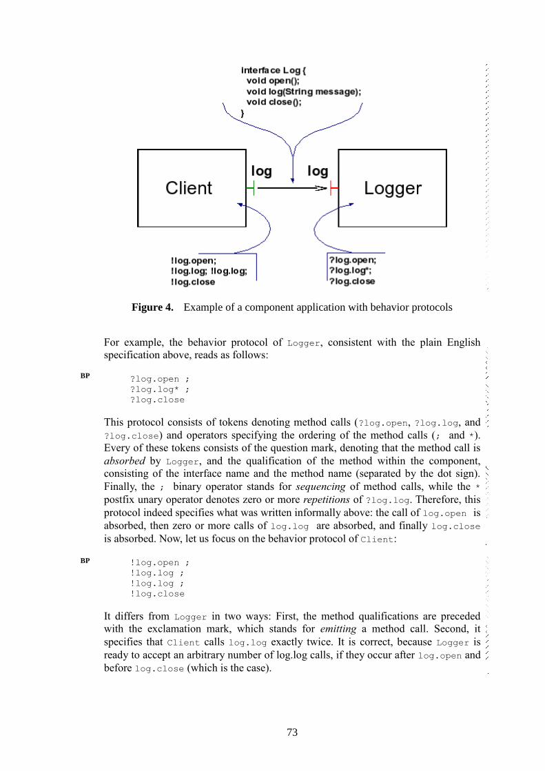
73
Figure 4. Example of a component application with behavior protocols
For example, the behavior protocol of Logger, consistent with the plain English
specification above, reads as follows:
?log.open ;
?log.log* ;
?log.close
This protocol consists of tokens denoting method calls (?log.open, ?log.log, and
?log.close) and operators specifying the ordering of the method calls (; and *).
Every of these tokens consists of the question mark, denoting that the method call is
absorbed by Logger, and the qualification of the method within the component,
consisting of the interface name and the method name (separated by the dot sign).
Finally, the ; binary operator stands for sequencing of method calls, while the *
postfix unary operator denotes zero or more repetitions of ?log.log. Therefore, this
protocol indeed specifies what was written informally above: the call of log.open is
absorbed, then zero or more calls of log.log are absorbed, and finally log.close
is absorbed. Now, let us focus on the behavior protocol of Client:
!log.open ;
!log.log ;
!log.log ;
!log.close
It differs from Logger in two ways: First, the method qualifications are preceded
with the exclamation mark, which stands for emitting a method call. Second, it
specifies that Client calls log.log exactly twice. It is correct, because Logger is
ready to accept an arbitrary number of log.log calls, if they occur after log.open and
before log.close (which is the case).
BP
BP

74
4.1.1 Events and Traces
Events are the keystone of behavior protocol semantics. Every event is atomic. We
define two types of events: requests and responses. Let m be the (fully qualified)
name of a method. Then, m^ (or m↑) stands for a request/call of m and m$ (or m↓)
stands for a response/return from m. Always, two components cooperate on an event:
one component emits the event and another component absorbs the event. To
distinguish between those two roles, we use the prefix ! for emitting and ? for
absorbing. If m is a method name, the symbols ?m^, ?m$, !m^, !m$ are called event
tokens. Recall Figure 4 from the beginning of Section 0. In the protocol of Client,
!log.log^ would stand for emitting the call of log.log, while ?log.log$ would
stand for absorbing the return from log.log. To specify that an event occurs as an
internal event of a component C (i.e., it results from a communication of C's
subcomponents), we use the # prefix. To provide a way to specify a request and the
corresponding response at once, we define abbreviations: if m is a (fully qualified)
name of a method, ?m is an abbreviation for the protocol (?m^ ; !m$) (the whole
method call from the point of view of the callee) and !m stands for (!m^ ; ?m$) (the
whole method call from the point of view of the caller). In fact, in the examples in
the Section 0 introduction, only these abbreviations were used to specify the
behavior, and usage of explicit requests and responses was not necessary.
We also define two more complex abbreviations: if P is an arbitrary protocol, ?m{P}
means that the call request of m is absorbed, and while m is processed, the component
behaves as specified by P; afterwards, the call response of m is emitted. In a similar
way, !m{P} means that P specifies the behavior of the caller between issuing the call
of m and receiving the response of m. The abbreviations not only serve as syntactic
sugar, allowing writing readable behavior protocols, but they also explicitly denote
pairing of events (requests and corresponding responses). In certain situations, such
information is essential for the behavior protocol checker. This is why for certain
types of interfaces, only an abbreviation can be used to specify the method call, and
the use of explicit event specification is forbidden (see Section 4.5.1).
A computation of a component application is formally described by a trace - a finite
sequence of event tokens. Every protocol specifies a set of traces. Recall the protocol
of Client from Figure 1.1:
!log.open ;
!log.log ;
!log.log ;
!log.close
It specifies a single trace:
<!log.open^, ?log.open$,
!log.log^, ?log.log$,
!log.log^, ?log.log$,
!log.close^, ?log.close$>
BP
BP
75
For Logger, the situation is more complex:
?log.open ;
?log.log* ;
?log.close
This protocol specifies an infinite number of traces, as it accepts arbitrary number of
calls to log.log.
We show the first three shortest traces specified by the protocol:
<?log.open^, !log.open$, ?log.close^, !log.close$>
<?log.open^, !log.open$, ?log.log^, !log.log$,
?log.close^, !log.close$>
<?log.open^, !log.open$, ?log.log^, !log.log$,
?log.log^, !log.log$, ?log.close^, !log.close$>
...
The set of all traces specified by a protocol P is denoted as L(P).
4.1.2 Behavior Protocol Basic Operators
For behavior protocols, the following basic operators are defined: sequencing
(denoted by ;), repetition (denoted by *), alternative (denoted by +), and-parallel
(denoted by |), and or-parallel (denoted by ||). We illustrate the meaning of the
operators (except the last one) on the following protocol of the Client component
from Figure 1.1:
!log.open ;
(
(!log.log | !log.log)
+
!log.log*
) ;
!log.close
Client, whose behavior is specified by this protocol, first calls log.open. Then, it
either calls log.log twice in parallel, or it calls log.log several times sequentially (or
it does not call log.log at all, as * stands for zero or more repetitions). At the end, it
calls log.close.
Or-parallel is defined as follows: if P and Q are protocols, (P || Q) stands for (P +
(P | Q) + Q).
4.1.3 Frame and Architecture Protocols
From the point of view of behavior, every component can be divided into two parts:
frame and architecture. The frame of a component C consists of all interfaces which
are provided or required by C to "outside world" (the components which are external
to C). The architecture of C consist of frames of C's direct subcomponents and
bindings between those frames (and also bindings between interfaces of C's
subcomponents and interfaces of C itself).
BP
BP
BP
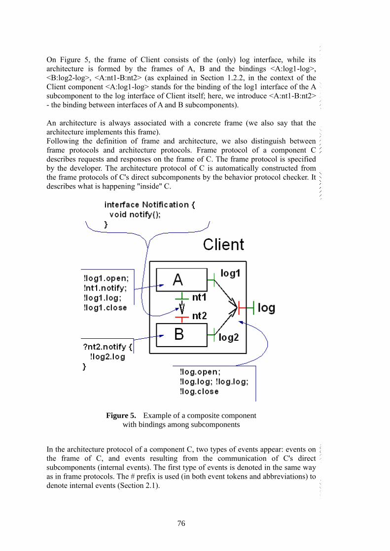
76
On Figure 5, the frame of Client consists of the (only) log interface, while its
architecture is formed by the frames of A, B and the bindings <A:log1-log>,
<B:log2-log>, <A:nt1-B:nt2> (as explained in Section 1.2.2, in the context of the
Client component <A:log1-log> stands for the binding of the log1 interface of the A
subcomponent to the log interface of Client itself; here, we introduce <A:nt1-B:nt2>
- the binding between interfaces of A and B subcomponents).
An architecture is always associated with a concrete frame (we also say that the
architecture implements this frame).
Following the definition of frame and architecture, we also distinguish between
frame protocols and architecture protocols. Frame protocol of a component C
describes requests and responses on the frame of C. The frame protocol is specified
by the developer. The architecture protocol of C is automatically constructed from
the frame protocols of C's direct subcomponents by the behavior protocol checker. It
describes what is happening "inside" C.
Figure 5. Example of a composite component
with bindings among subcomponents
In the architecture protocol of a component C, two types of events appear: events on
the frame of C, and events resulting from the communication of C's direct
subcomponents (internal events). The first type of events is denoted in the same way
as in frame protocols. The # prefix is used (in both event tokens and abbreviations) to
denote internal events (Section 2.1).
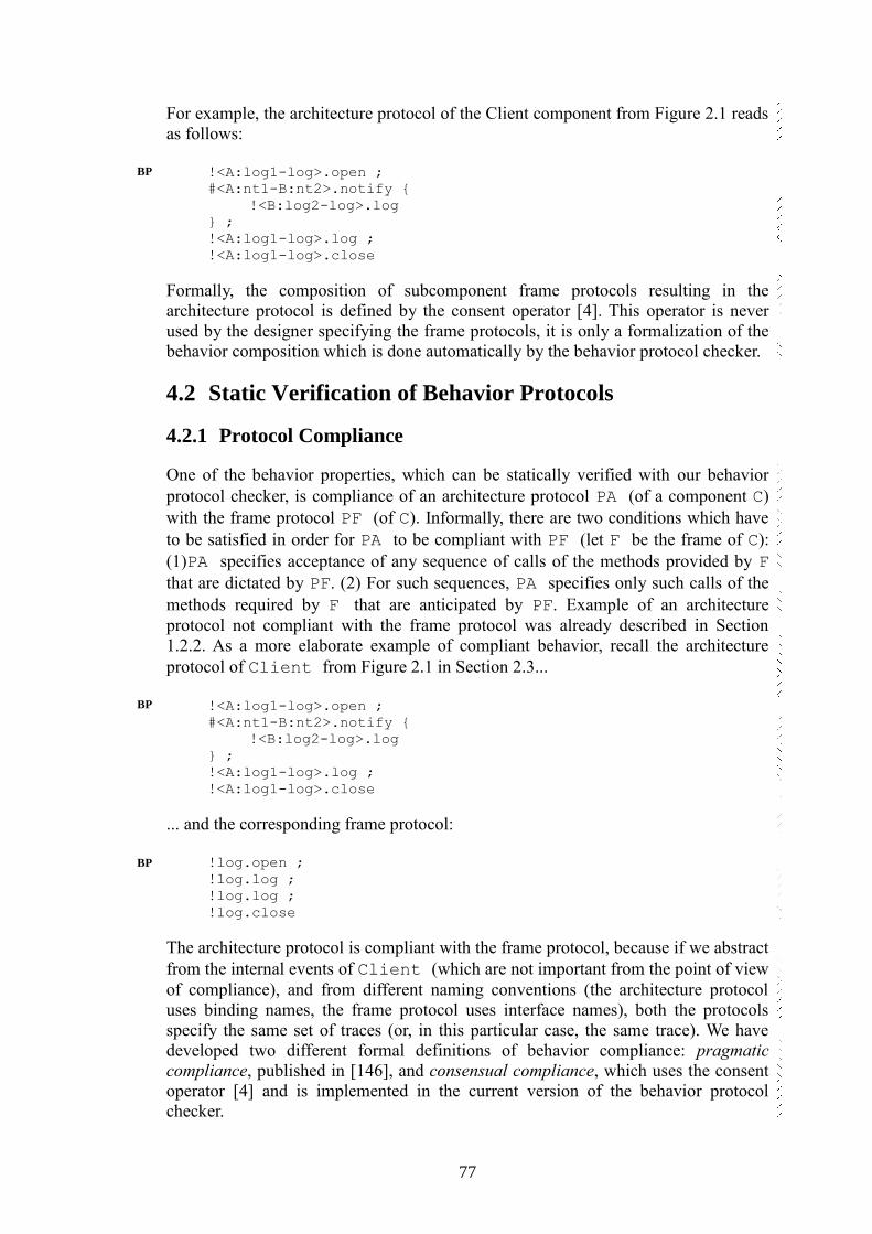
77
For example, the architecture protocol of the Client component from Figure 2.1 reads
as follows:
!<A:log1-log>.open ;
#<A:nt1-B:nt2>.notify {
!<B:log2-log>.log
} ;
!<A:log1-log>.log ;
!<A:log1-log>.close
Formally, the composition of subcomponent frame protocols resulting in the
architecture protocol is defined by the consent operator [4]. This operator is never
used by the designer specifying the frame protocols, it is only a formalization of the
behavior composition which is done automatically by the behavior protocol checker.
4.2 Static Verification of Behavior Protocols
4.2.1 Protocol Compliance
One of the behavior properties, which can be statically verified with our behavior
protocol checker, is compliance of an architecture protocol PA (of a component C)
with the frame protocol PF (of C). Informally, there are two conditions which have
to be satisfied in order for PA to be compliant with PF (let F be the frame of C):
(1)PA specifies acceptance of any sequence of calls of the methods provided by F
that are dictated by PF. (2) For such sequences, PA specifies only such calls of the
methods required by F that are anticipated by PF. Example of an architecture
protocol not compliant with the frame protocol was already described in Section
1.2.2. As a more elaborate example of compliant behavior, recall the architecture
protocol of Client from Figure 2.1 in Section 2.3...
!<A:log1-log>.open ;
#<A:nt1-B:nt2>.notify {
!<B:log2-log>.log
} ;
!<A:log1-log>.log ;
!<A:log1-log>.close
... and the corresponding frame protocol:
!log.open ;
!log.log ;
!log.log ;
!log.close
The architecture protocol is compliant with the frame protocol, because if we abstract
from the internal events of Client (which are not important from the point of view
of compliance), and from different naming conventions (the architecture protocol
uses binding names, the frame protocol uses interface names), both the protocols
specify the same set of traces (or, in this particular case, the same trace). We have
developed two different formal definitions of behavior compliance: pragmatic
compliance, published in [146], and consensual compliance, which uses the consent
operator [4] and is implemented in the current version of the behavior protocol
checker.
BP
BP
BP
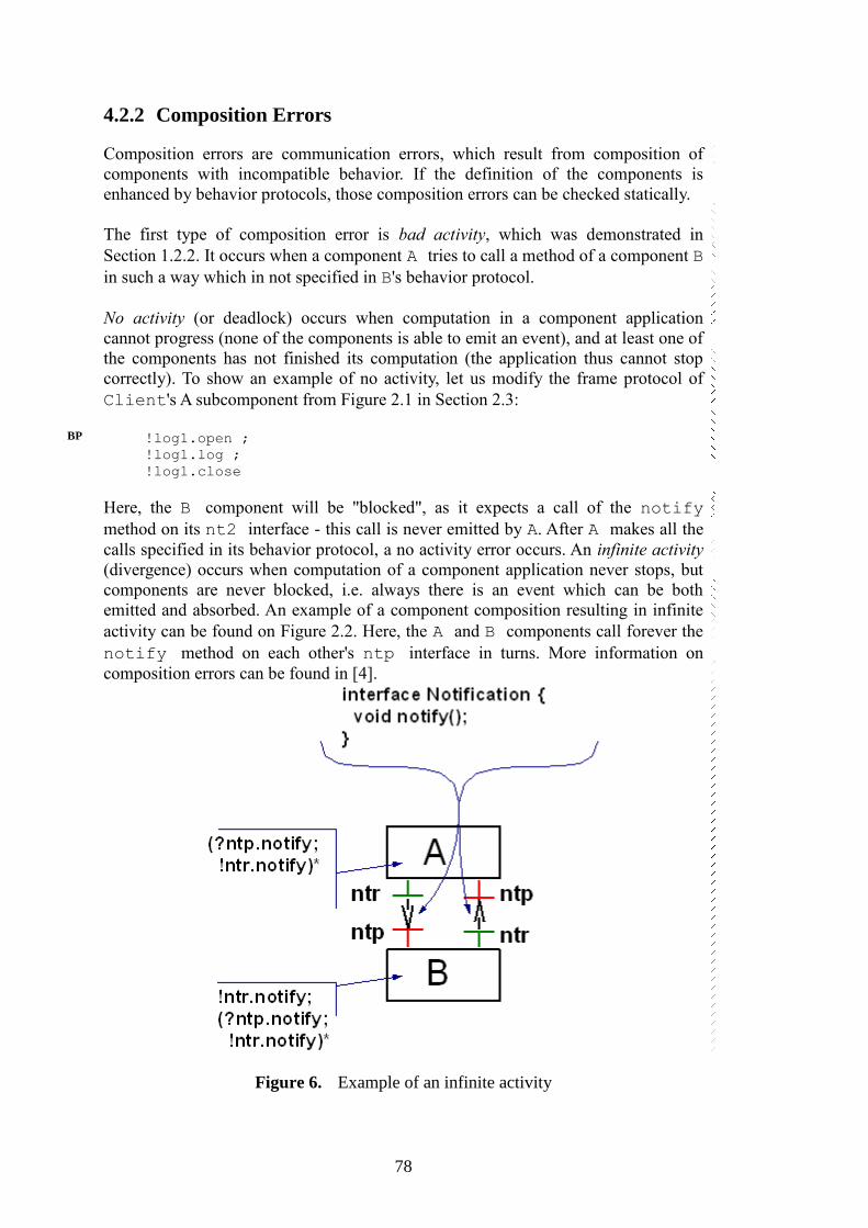
78
4.2.2 Composition Errors
Composition errors are communication errors, which result from composition of
components with incompatible behavior. If the definition of the components is
enhanced by behavior protocols, those composition errors can be checked statically.
The first type of composition error is bad activity, which was demonstrated in
Section 1.2.2. It occurs when a component A tries to call a method of a component B
in such a way which in not specified in B's behavior protocol.
No activity (or deadlock) occurs when computation in a component application
cannot progress (none of the components is able to emit an event), and at least one of
the components has not finished its computation (the application thus cannot stop
correctly). To show an example of no activity, let us modify the frame protocol of
Client's A subcomponent from Figure 2.1 in Section 2.3:
!log1.open ;
!log1.log ;
!log1.close
Here, the B component will be "blocked", as it expects a call of the notify
method on its nt2 interface - this call is never emitted by A. After A makes all the
calls specified in its behavior protocol, a no activity error occurs. An infinite activity
(divergence) occurs when computation of a component application never stops, but
components are never blocked, i.e. always there is an event which can be both
emitted and absorbed. An example of a component composition resulting in infinite
activity can be found on Figure 2.2. Here, the A and B components call forever the
notify method on each other's ntp interface in turns. More information on
composition errors can be found in [4].
Figure 6. Example of an infinite activity
BP
79
4.2.3 Incomplete Bindings
We say that a component architecture has incomplete bindings, if there exists an
interface (either provided or required), which does not participate in any binding (we
call such an interface an unbound interface). The existence of an unbound interface is
not necessarily a design error: this typically happens when the designer reuses a
component developed originally for different application and decides to utilize only a
part of the component's functionality. If the behavior of the components in the
architecture is specified using behavior protocols, it is possible to statically check
whether the incomplete bindings cause a problem.
An unbound provided interface can cause bad activity or no activity (Section 2.4.2).
On the other hand, an unbound required interface can cause a new type of
composition error: unbound requires error. Unbound requires error occurs when a
component tries to call a method on its required interface, which is unbound. An
example of a component application with one unbound required interface (the nt
interface of the A component) is shown on Figure 2.3. On the ch interface of A, the
a or the b method can be called. If b is called, A reacts by calling nt.notify.
As the B component calls only ch.a, the A:nt.notify method is never called
and the fact that A:nt is unbound does not cause any problem. On the other hand, if
the behavior protocol of B was (!ch.b*), it would result in an unbound requires
error. More information on incomplete bindings can be found in [5].
Figure 7. Example of incomplete bindings
4.3 Runtime Verification of Behavior Protocols
The run-time checker monitors the events on the external interfaces of a component
(the trace) and checks whether this trace is one of those specified by the frame

80
protocol of the component. If not, it is considered to be an error. The main reason for
using the run-time checker is verification of the composite components with dynamic
architectures (which cannot be verified statically). Also, run-time checking is an
alternative to static checking in the situations when the architecture of a (composite)
component is so complex that the static checker cannot be used. Last but not least,
run-time checker can be used to check the compliance of a primitive component
behavior with the frame protocol (this cannot be done using the static protocol
checker in principle, because there are no subcomponent frame protocols). We show
the functionality of the run-time checker on the example from Figure 1.1 in Section
1.2.1. The frame protocol of Client specifies that the log.log method has to
be called after log.open has been called. If log.close were called instead at
that moment, the run-time checker would detect an error. What exactly happens when
such an error is detected depends on the configuration of the run-time checker.
Typically, the error is reported and logged within the runtime-checking framework.
The runtime checking framework may throw an exception in the calling thread to
notify the application about the erroneous call, or the application may continue
without being affected. In either case, the run-time checking of the component
(whose frame protocol was violated) is stopped. It is not possible to continue run-
time checking of the component in this case, as the behavior protocols formal model
does not support "error recovery". The run-time checker also detects the violation of
the frame protocol caused by the component's environment (the "outer world"). For
example, if the frame protocol of Client were
!log.open;
!log.open;
!log.close
(i.e., to start by calling log.open twice) and Client behaved in compliance
with this protocol (so that no protocol violation would be detected by the run-time
checker for Client), error would be reported for Logger, as its protocol does not
allow to accept a call of the log.open method twice.
4.4 Code Analysis
The purpose of code analysis of a primitive component is to check whether the
component's behavior is bounded by its frame protocol, that means checking whether
the component can accept and emit method calls on its frame interfaces only in
sequences that are determined by its frame protocol. Main advantage of code analysis
over runtime checking is that all techniques of code analysis are exhaustive, i.e. they
check all the possible runs of the verified code. We decided to employ model
checking, which is one of the more popular techniques of software code analysis.
Model checking [47] is a formal method of verification of finite state systems. The
basic idea is that a model checker checks whether the model of a target system
satisfies the property expressed in some property specification language. The
checking is done by traversal of the state space that is generated from the model.
Some model checkers accept as input the model manually created by the user, while
others are able to automatically extract the model from the source code. However,
both approaches have severe drawbacks. Manual construction of the model is a
tedious and error-prone process. On the other hand, automated extraction of the
BP

81
model faces the problem that the model is an abstraction and, therefore, it may
represent behavior not possible in the original program. Consequently, a model
checker may then find errors that are not present in the program (i.e., false
negatives). Fortunately, there exist model checkers that work directly with the
implementation of a target system - Java Pathfinder is an example of such a model
checker.
Properties to be checked are usually expressed via temporal logic (CTL, LTL), or in
the form of assertions. Some model checkers are also able to check for a fixed set of
special properties (deadlocks, uncaught exceptions, etc).
The biggest problem of model checking with respect to practical use of this
technique is the size of the state space typical for software systems (the problem of
state explosion). However, decomposition of a software system into components
helps to mitigate the problem. A component usually generates smaller state space
than the entire system and, therefore, can be checked with fewer requirements on
space and time.
In our case, we use model checking to check whether a primitive component is
bounded by its frame protocol or not. And since most implementation of the Fractal
Component Model (used in our projects presented later) are Java-based (including
the reference implementation Julia), we decided to use the Java PathFinder model
checker (JPF) [133].

82
Chapter 5 CRE Case-study
The CRE case-study presented in this chapter was created as part of our CRE
(Component Reliability Extensions) project [2]. The project was done in cooperation
with France Telecom and the goal of the project itself can be summarized by a short
citation from [2]: “The purpose of this project is to extend the Fractal Component
model and its Julia implementation with support for Behavior Protocols”. The
following Section 5.1 presents a novel case study created in the CRE project to verify
the new techniques implemented into Julia and Fractal. Section 5.2 describes our
integration of Behavior Protocol checker into Fractal, Section 5.3 and Section 5.4
present problems identified in modeling the CRE case-study in the extended
Fractal/Julia, and propose solution to mitigate them.
5.1 The Case-study
In this section we present the case-study as engineered in the CRE project. As most
of the text is verbatim copied from the project’s results manual, we retained its
original wording – especially the case-study is referred to as “the demo” in the rest of
the text. The case-study was prepared with cooperation with the France Telecom to
reflect a typical application of one of its business domains. It was specially crafted in
a way to employ a diverse set of architectural features, so that we would be able to
stress test our modeling approaches to the edge.
The demo presents a prototype implementation of a payment system for public
Internet access on airports. It is designed so that clients of several air-carriers from
the same group (e.g. SkyTeam) can have access to the Internet. Clients access the
system via a wireless network (e.g. WiFi); before being able to establish
communication with the Internet, they have to authenticate themselves and/or pay for
the service. There are currently three different ways a client can gain access to the
Internet:
All clients that have a valid fly ticket for first class or business class have full
Internet access during the ticket validity period free of charge. For this access method
the fly ticket identification number is used during the client login as authentication
credentials in the system.
Any client that has a valid Frequent Flyer Card and has any valid fly ticket has also
full Internet access during the ticket validity period free of charge. The Frequent
Flyer Card identification number is used as credentials. The system checks that a
valid fly ticket exists for the card.
Any client of any air-carrier can prepay Internet access by a credit card. The clients
using this method will get a user name and a password that are valid for a certain
amount of time (e.g. 1 week or 1 month) and in this time period the prepaid time for
Internet access needs to be used up (else the remaining prepaid time will expire).
CREman
83
The client session (the client’s ability to communicate with Internet servers) starts
when the client authenticates using one of the previous methods and terminates when
one of the following events occurs:
The client disconnects from the wireless network – any prepaid time not used up
during the session being terminated can be used up in future sessions assuming the
client’s user name will not expire until then.
Client’s fly ticket becomes invalid or all of the client’s prepaid time is used up – the
session terminates immediately and the client can start a new prepaid session.
The key part of the system behavior will be implemented in Fractal components.
However, the clients will communicate with the system via JSP web pages that will
then call the Fractal components with appropriate requests. The demo environment is
divided into three areas/networks:
1. Airport WiFi – The public wireless network that clients connect to.
2. Airport LAN – All demo Fractal components run on computers in this
network. The communication between this network and the Airport WiFi is
separated by the Firewall that is controlled by the Firewall Fractal
component.
3. Internet – The part representing the outer world. It hosts central servers and
web services (e.g. credit card web services, air-carriers database servers) and
also the client communication goes there (if not blocked by the Firewall)
On the lowest level the client connections are managed by the DhcpServer Fractal
component. This component assigns IP addresses to new clients and notifies other
demo Fractal components when clients disconnect, so that their sessions can be
terminated. The DhcpServer component might also communicate with some sort of
wireless network access point, in order to get more accurate information about client
connection and disconnection events.
5.1.1 Demo Behavior
See the diagram of the whole demo in Appendix A.
Note: The numbered symbols like 2 , 3a , 3b or 3c reference the appropriate numbered
steps in the picture.
Initial state:
No clients connected
Any DHCP communication is allowed through the Firewall
All HTTP/HTTPS requests from clients are redirected to the airport’s
WebServer residing in the Airport LAN. All such requests are redirected to
the Login page, that all clients use to enter login credentials to open
connection to the Internet.
84
All other outgoing or incoming communication from/to clients is initially
blocked 0 by the Firewall service.
Event: A new client connects to the Airport WiFi network
1. The Client sends a DHCP request for an IP address 1 and the DhcpServer replies 1 assigning a new IP address to the Client (see section 2.1 for a detailed
description of DhpcServer composite component behavior). The Client then uses
this IP address for all communication with the system and during any access to
the Internet. The assigned IP address also serves as a unique client identifier.
2. The Client enters the Login page (by typing any URL in the web browser) 2
3. The Client then continues in one of the three possible ways depending on the
access method selected:
4. Free access using first class or business class fly ticket ID:
4.1. The Client fills the fly ticket ID in the login form
4.2. The Login page calls the Arbitrator:ILogin.LoginWithFlyTicketId(Id)
method with the fly ticket Id supplied by the Client 3a
4.3. The Arbitrator calls the FlyTicketDatabase:IFlyTicketAuth.CreateT
oken( FlyTicketId) method 4a to create the Token component
representing the “logged in” state of the Client
4.4. The FlyTicketDatabase:FlyTicketClassifier component then selects t
he appropriate fly ticket database component depending on the supplied fly
ticket ID and calls the IFlyTicketDb.GetTicketValidity(FlyTicketId)
method on it 5a (CsaDbConnection component is selected in the example).
4.5. The database component then uses any proprietary protocol to connect to the
air-carrier’s database server to get the requested information 6a
4.6. If the supplied FlyTicketId is valid then the associated fly ticket validity
time is passed back to the FlyTicketClassifier component 5a
4.7. The FlyTicketClassifier creates a new instance of the Token component 7a with the validity set to the time returned in the previous step. The Token
component instance will be created without the Token:CustomToken inner
component as it is not needed in this type of authentication.
4.8. Further steps are common for all three authentication methods (to continue
skip the specific steps for methods/steps 5 and 6).
5. Free access using the Frequent Flyer Card ID:
5.1. The Client fills the Frequent Flyer Card ID in the login form
5.2. The Login page calls the Arbitrator:ILogin.LoginWithFrequentFlyerId(Id)
method with the Frequent Flyer Card Id supplied by the Client 3b
85
5.3. The Arbitrator calls the CreateToken(FrequentFlyerId) method 4b on the
FrequentFlyerDatabase:IFreqFlyerAuth interface to create the Token
component representing the “logged in” state of the Client
5.4. The FrequentFlyerDatabase component then connects to the central database
of issued Frequent Flyer Cards 5b (“SkyTeam Frequent Flyer Database”) and
checks the FrequentFlyerId validity
5.5. If the supplied Frequent Flyer Card ID is valid then the
FlyTicketDatabase:IFlyTicketDb.GetTicketByFreqFlyerId( FrequentFlyerId)
method is called 6b to check if there exists any valid fly ticket bought with
the Frequent Flyer Card at any air-carrier’s office of the group
5.6. The FlyTicketDatabase:FlyTicketClassifier requests the same information
from all of the database connection providers by calling the
IFlyTicketDb:GetTicketByFreqFlyerId method on them 7b
5.7. Each of the database connection components then connects to its own air-
carrier’s database server 8b to retrieve list of all valid fly tickets bought using
the supplied FrequentFlyerId.
5.8. The FlyTicketClassifier gathers responses from all fly ticket databases 7b
and the resulting list of valid fly tickets (possibly empty) is retured back
from the FlyTicketDatabase:IFlyTicketDb. GetTicketByFreqFlyerId
(FrequentFlyerId) call 6b
5.9. If the resulting list of valid fly tickets is not empty the
FrequentFlyerDatabase selects one of the tickets that is currently valid and
calls the FlyTicketDatabase:IFlyTicketAuth.CreateToken(FlyTicketId)
method 9b to create a new instance of the Token component. The following
steps to create the Token component are similar to the most of the steps of
the a) authentication method:
5.10. The FlyTicketDatabase:FlyTicketClassifier component selects the
appropriate fly ticket database component depending on the supplied fly
ticket ID and calls the IFlyTicketDb.GetTicketValidity(FlyTicketId) method
on it 10b (AfDbConnection component is selected in the example).
5.11. The database component then uses any proprietary protocol to connect to
the air-carrier’s database server to get the requested information 11b
5.12. If the supplied FlyTicketId is valid then the associated fly ticket validity
time is passed back to the FlyTicketClassifier component 10b
5.13. The FlyTicketClassifier creates a new instance of the Token component 12b with the validity set to the time returned in the previous step. The Token
component instance will be created without the Token:CustomToken inner
component as it is not needed in this type of authentication.
5.14. The instance of the Token component 12b returned from the
FlyTicketDatabase:IFlyTicketAuth.CreateToken(FlyTicketId) method call 9b
is then returned back 4b to the Arbitrator component
86
5.15. Further steps are common for all three authentication methods (to continue
skip the specific steps for method/step 6).
6. Prepaid access
6.1. If the Client does not possess a user name and a passport to a prepaid access
account then such an account needs to be created first:
6.2. The Client fills his or her credit card number and the card expiration date
into the account creation form on the Login page. The Client also chooses
the amount of time that will be prepaid to his or her new account.
6.3. The Client selects an AccountId or a random AccoundId can be generated by
calling the AccountDatabase:IAccount. GenerateRandomAccoundId()
method.
6.4. The Client selects a password or a random password is generated by the
Login page
6.5. The Login page calls the AccountDatabase:IAccount.CreateAccount(
AccountId, Password) method 3c to create a new prepaid account for the
Client
6.6. The AccountDatabase creates a new account in the central database 4c . The
account will have default validity or timeout period associated with it (e.g. 1
week or 1 month as mentioned earlier) and will have no Internet access time
prepaid.
6.7. The Login page uses the AccoundId and other information supplied by the
Client to call the AccountDatabase:IAccount.RechargeAccount(AccountId,
CardId, CardExpirationDate, PrepaidTime) method 5c used to pay for more
time to access the Internet.
6.8. The AccountDatabase calls the CardCenter:ICardCenter.Withdraw(CardId,
CardExpirationTime, Amount) method 6c to withdraw the correct amount
(depending on the PrepaidTime) from the Client’s account.
6.9. The CardCenter component then selects the right credit card authorization
center (“VISA Card Center” in the example), checks the validity of the
requests and communicates with the card center 7c to process the request.
6.10. If the requested amount was successfully withdrawn from the Client’s
account the AccountDatabase enters the new prepaid time into the Client’s
account record in the central Account Database 8c and success is returned to
the Login page 5c .
6.11. The Client fills his or her account used id and password into the login form
on the Login page (these credentials are generated/selected during the
account creation)
6.12. The Login page calls the Arbitrator:ILogin.LoginWithAccountId(
AccountId, Password) method with the credentials supplied by the Client 9c
87
6.13. The Arbitrator calls the CreateToken(AccountId, Password) method 10c on
the AccountDatabase:IAccountAuth interface to create the Token component
representing the “loged in” state of the Client
6.14. The AccountDatabase component gets the prepaid time of the account
from the central Account Database 11c
6.15. The AccountDatabase creates a new instance of the Token component 12c
with its validity time set to the prepaid time from the previous step. The
Token component instance will contain the CustomToken subcomponent. If
the Client’s session terminates the CustomToken component is used to
communicate the amount of prepaid time already used up back to the
AccountDatabase via the IAccount:AdjustAccountPrepaidTime(AccountId,
SecurityCookie, TimeLeft) method 21 . The SecurityCookie is a random
string generated during creation of the Token component and it is passed by
the AccountDatabase component to the CustomToken component during its
construction. The CustomToken saves the SecurityCookie, so that it can use
it later to prove its connection to the AccountId specified in the
IAccount:AjustAccountPrepaidTime call.
The following steps are common for all three authentication methods:
7. Now the Arbitrator component already has a reference to a new instance of the
Token component returned either from the FlyTicketDatabase, the
FrequentFlyerDatabase or the AccountDatabase component, depending on the
authentication method selected. The Arbitrator adds this reference into its internal
table that maintains the bijection between Token component instances and
connected Clients (Clients’ IP addresses)
8. The Arbitrator calls the Firewall:IFirewall.DisablePortBlock(IpAddress) method 13 ( 8a or 13b or 13c )
9. The Firewall component uses a proprietary communication mechanism to
forward the request to the Firewall system service 14 . The Firewall service opens
all communication ports to/from the Client and stops redirecting all
HTTP/HTTPS communication from the Client to the airport’s WebServer 15 – Cancel port block . Until the session terminates the Client can access the Login page
only using a special URL (server address that was displayed on the Login page).
If the Client forgets the URL, he or she can simply disconnect from the wireless
network (this action will automatically terminate the current session) and
reconnect again, so that a new session is started and all Client requests are
redirected back to the Login page.
10. The Client has now full access to the Internet 16 until its session terminates (its
access Token becomes invalid or he or she disconnects from the Airport WiFi
network).
Event: A client disconnects from the Airport WiFi network 17 – Client disconnects :
1. If, after certain amount of time, the Client does not send the “Renew IP address”
DHCP request the DhcpServer:IpAddressManager component will deduce that

88
the Client has disconnected and will call the Abitrator:IDhcpCallback
:IpAddressInvalidated(IpAddress) method 18 (see section 2.1 for a more detailed
description of this process). This will start the process of terminating current
Client’s session
2. The Arbitrator calls the IToken.InvalidateAndSave() method on the right
Token component instance (based on the IP address passed in the
IpAddressInvalidated call and the IP address/Token instance mapping stored in
the internal table)
3. If the Token component instance contains the CustomToken subcomponent (i.e. if
the instance was created by the AccountDatabase:IAccountAuth.CreateToken
calls) the following steps will occur too:
4. The Token:ValidityChecker component calls the Token:CustomToken
.InvalidatingToken( TimeLeft) method 20 passing it the amount of time until the
Token should have become invalid.
5. The CustomToken calls the AccountDatabase:IAccount
.AdjustAccountPrepaidTime(AccountId, SecurityCookie, TimeLeft) method 21 to
update the amount of prepaid time left on the Client’s account.
6. The AccountDatabase updates the prepaid time in the central database 22 .
7. The Token:ValidityChecker component calls the Arbitrator:ITokenCallback
.TokenInvalidated(TokenId) method 23 . This signals the Arbitrator component
that the Token have become invalid and that the associated Client’s session
should be terminated.
8. The Arbitrator calls the Firewall:IFirewall.EnablePortBlock(IpAddress) 24
9. The Firewall component then communicates with the Firewall system service 25
so that all existing connections to or from the Client are closed and no new ones
are allowed (except for the DHCP communication) and that all HTTP/HTTPS
requests from the Client are again redirected to the Login page on the WebServer 26 .
10. The Client’s session is terminated and, from the point of view of the Client, the
system is in the same state as it was in the initial state.
11. Event: Client’s Token becomes invalid – i.e. Client’s fly ticket becomes
invalid or all of the prepaid time is used up:
12. The steps that will follow are similar to the steps following the previous event.
The only difference is that the session termination is not initiated by the
DhcpServer component, but by one of the Token components itself.
13. The Token:Timer component times out – i.e. Token validity has ended and it calls
the ValidityChecker:ITimerCallback.Timeout() method 19ß .
19α
89
If the Token component instance contains the CustomToken subcomponent (i.e. if the
instance was created by the AccountDatabase:IAccountAuth.CreateToken calls) the
following steps will occur too:
14. The Token:ValidityChecker component calls the Token:CustomToken
.InvalidatingToken(TimeLeft) method 20 passing the amount of time until the
Token should have become invalid.
15. The CustomToken calls the
AccountDatabase:IAccount.AjustAccountPrepaidTime( AccountId,
SecurityCookie, TimeLeft) method 21 to update the amount of prepaid time left on
Client’s account.
16. The AccountDatabase updates the prepaid time in the central database 22 .
17. The Token:ValidityChecker component calls the Arbitrator:ITokenCallback
.TokenInvalidated( TokenId) method 23 . This signals the Arbitrator component
that the Token have become invalid and that the associated Client’s session
should be terminated.
18. The Arbitrator calls the Firewall:IFirewall.EnablePortBlock(IpAddress) 24
19. The Firewall component then communicates with the Firewall system service 25
so that all existing connections to or from the Client are closed and no new ones
are allowed (except for the DHCP communication) and that all HTTP/HTTPS
requests from the Client are again redirected to the Login page on the WebServer 26 .
20. The Client’s session is terminated and, from the point of view of the Client, the
system is in the same state as it was in the initial state.
5.1.2 DhcpServer Component Description and Behavior
The DhcpServer component can behave in two different ways:
1. IP addresses for new clients are automatically generated (by a preconfigured
pattern – e.g. valid IP address range) by the DhcpServer component. In this
scenario the IP/MAC address mappings are stored in the TransientIpDb
database component only and IpAddressManager’s IIpMacPermanentDb
interface is not used at all (this implies that the
DhpcServer:IIpMacPermanentDb interface does not need to be bound in this
scenario). This scenario is used by the demo.
2. The second option is that the IP/MAC address mappings can be permanently
stored in an external database component (providing an IIpMacDb interface)
and the DhcpServer assigns IP addresses to new clients according to their
MAC address and the mapping stored in the database. As in the first scenario
the IP address/MAC address mapping is also temporarily stored in the
TransientIpDb component for the time the corresponding IP address is
actually assigned to the client. Calling the
DhcpServer:IManagement.UsePermanentIdDatabase method activates this
behavior.

90
Event: A new client connects to the Airport WiFi network
1. The Client sends a DHCP request 1 for an IP address. This request is accepted by
the DhcpServer:DhcpListener component.
2. The DhcpListener component calls the
IpAddressManager.RequestNewIpAddress method 1.1 .
3. The IpAddressManager component determines a IP address for the new client –
this action is different for each of the DhcpServer usage scenarios:
4. IpAddressManager tries to generate a new IP address and checks whether it has
been already assigned – by calling the IIpMacTransientDb.GetMacAddress 1.2
method. If the generated IP address is already used it will generate another one
and repeat the check.
5. IpAddressManager calls the IIpAddressPermanentDb.GetIpAddress method to
check if a mapping for client’s MAC address exists. If the mapping is not found
the IpAddressManager can try to generate an automatic IP address as in the
previous scenario.
6. The IP address with client’s MAC address is then added by the
IpAddressManager to the TransientIpDb database by calling it’s IIpMacDb.Add 1.3 method.
7. The assigned IP address is returned to the client via returning the
IDhcpListenerCallback.RequestNewIpAddress method call 1.1 from
IpAddressManager component back to the DhcpListener. The assigned IP address
is then used as a unique client identifier by the rest of the system.
8. The Client can enter the Login page 2 (by typing any URL in the web browser)
Event: A client disconnects from the Airport WiFi network 17 – Client disconnects :
The client disconnection event can occur, or be detected in one of the two ways:
1. If, after certain amount of time, the Client does not send the “Renew IP address”
DHCP request to the IpAddressManager component (via
DhcpListerner:IDhcpListernerCallback.RenewIpAddress method call) the present
timer will expire calling the IpAddressManager:TimerCallback.Timeout method.
2. The WiFi Access Point detects client’s disconnection from the WiFi network and
notifies the DhcpServer:DhcpListener component of that event. The
DhcpListerner will call the
IpAddressManager:IDhcpListenerCallback.ReleaseIpAddress method 17.1 .
2.1. The IpAddressManager will the remove the IP address/MAC address
mapping from the TransientIpDb database component by calling it’s
IIpMacTransientDb.Remove method 17.2 .
91
2.2. The IpAddressManager will notify the rest of the system of client
disconnection by calling the IDhcpCallback.IpAddressInvalidated 17.3
method.
2.3. That will lead into calling Abitrator:IDhcpCallback.IpAddressInvalidated
method 18 that will start the process of terminating current Client’s session.
5.2 BPC and Fractal Integration
One part of the CRE project was also to integrate the Behavior Protocol Checker
(BPC) and the Fractal component model – namely its Julia implementation for Java
platform. During the integration process we had to tackle many problems and
provide solution to many issues – details can be found in the original manual – here
in the following text we will present only an overview of the key problems we have
faced and the ones directly related to the goals of the thesis we will provide a more
detailed analysis.
To successfully finish the integration we had to introduce several assumptions about
the Fractal component model and also extend some of its basic features:
The Fractal component model specification is very flexible (and structured in several
conformance levels), consequently, many concrete component systems comply with
it. To make the integration of behavior protocols into Fractal possible, we take the
following additional assumptions:
(1) In Fractal, every component has internal and external interfaces. We suppose that
for every external interface there exists an internal interface of the same type (and
vice versa). In addition, an event on an external interface immediately causes the
complementary event on the corresponding internal interface, and these two events
happen atomically. In a similar way, an event on an internal interface immediately
causes the complementary event on the corresponding external interface (and the two
events happen atomically).
(2) Interfaces in Fractal are connected by bindings. We suppose that an event
occurring on an interface I causes immediately the complementary event on the
interface I is bound to, and the two events happen atomically, assuming I is bound to
exactly one interface. If I is bound to more interfaces, the events on those interfaces
do not have to happen atomically.
Next, as we associate a frame protocol with each component of an application, and
also some environment-related information with each primitive component of an
application. Thus, to enable the users to use Fractal ADL for describing the
architecture of Fractal applications, we had to extend the Fractal ADL syntax to
accommodate the frame protocol and environment declarations.
5.2.1 Interceptors
While extending Fractal and Julia with support for runtime checking of compliance
of component behavior with the specified protocol, we have encountered a number of
issues, some of which have required modifications to Julia. In this section, we
CREman
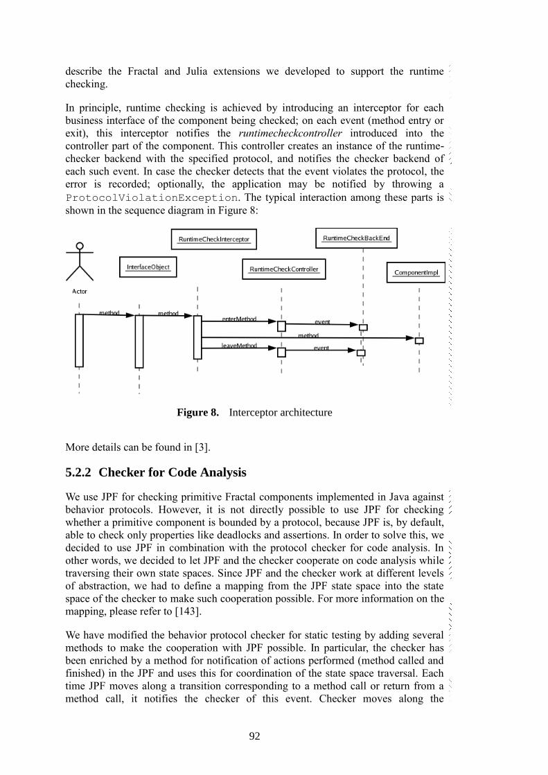
92
describe the Fractal and Julia extensions we developed to support the runtime
checking.
In principle, runtime checking is achieved by introducing an interceptor for each
business interface of the component being checked; on each event (method entry or
exit), this interceptor notifies the runtimecheckcontroller introduced into the
controller part of the component. This controller creates an instance of the runtime-
checker backend with the specified protocol, and notifies the checker backend of
each such event. In case the checker detects that the event violates the protocol, the
error is recorded; optionally, the application may be notified by throwing a
ProtocolViolationException. The typical interaction among these parts is
shown in the sequence diagram in Figure 8:
Figure 8. Interceptor architecture
More details can be found in [3].
5.2.2 Checker for Code Analysis
We use JPF for checking primitive Fractal components implemented in Java against
behavior protocols. However, it is not directly possible to use JPF for checking
whether a primitive component is bounded by a protocol, because JPF is, by default,
able to check only properties like deadlocks and assertions. In order to solve this, we
decided to use JPF in combination with the protocol checker for code analysis. In
other words, we decided to let JPF and the checker cooperate on code analysis while
traversing their own state spaces. Since JPF and the checker work at different levels
of abstraction, we had to define a mapping from the JPF state space into the state
space of the checker to make such cooperation possible. For more information on the
mapping, please refer to [143].
We have modified the behavior protocol checker for static testing by adding several
methods to make the cooperation with JPF possible. In particular, the checker has
been enriched by a method for notification of actions performed (method called and
finished) in the JPF and uses this for coordination of the state space traversal. Each
time JPF moves along a transition corresponding to a method call or return from a
method call, it notifies the checker of this event. Checker moves along the
93
corresponding transition in its own state space. Should not such a transition exist
within the checker's state space, an error is reported to the user and the
implementation is considered not to be bound by the protocol. To treat all the
combination of implementations and protocols correctly as well as to be able to
handle cycles, it is necessary to coordinate the traversal in the following way: Each
time JPF would backtrack within the state space because of being in an already
visited state it asks the checker for permission. Only in situations when both JPF and
the checker would backtrack at this point when executed on their own (i.e., if being
in an already visited state), backtracking is allowed. Hence, the bounding relation can
be checked correctly.
More detailed analysis of JPF application to the CRE project can be found in [3].
5.3 Modeling the CRE Demo
When modeling and implementing the demo application proposed in Section 5.1
using behavior protocols and Fractal component model, we ran into several problems
that needed to be solved. The following Section 5.3.1, 5.3.2, and Section 5.3.3, as
well as Section 5.4 are dedicated to describe all the problems identified. All of the
sections, with the exception of Section 5.3.1, also provide solutions to the problems
that were devised as part of the CRE project. The Section 5.3.1 describes the most
severe problem encountered (problem of modeling dynamic component
architectures) that we were unable to solve in the CRE project without considerably
changing the techniques available at that time. However later in Chapter 7 we
provide a final solution to this problem and in Section 7.5 we return back to this
case-study and remodel it with the newly introduced concepts and verify their ability
to solve the problem described below.
5.3.1 Token Component Dynamism
One of the key challenges in the CRE project was to model, implement and verify
correctness of the Token component from the case-study demo application. The basic
functionality of the Token component is simple – it represents state of a client
logged-in to the system, i.e. for each initiated session to the system there should exist
a single Token component instance representing it – and this is the problem. The
running application does not contain only a single Token instance, but multiple
Token instances can be present at runtime, moreover, they are dynamically created as
new clients arrive and dynamically destroyed as clients log out or disappear.
Fortunately in the Fractal component model this can be implemented without
problems as it supports dynamic component instantiation at runtime – the problem is
that any newly created components are represented only as references to them and
actually lay outside of applications architecture, and the component model runtime
loses control of their further evolution in the application (a problem tackled before in
Section 2.3.6). The application’s architecture the Fractal component model
understands is only static and represents a view on component relations at start of the
application – i.e. any further changes are not captured there.
As the behavior protocols are based on similar CBSE concepts, they also do support
only static architectures. In order to solve the Token problem (that leads to a dynamic
architecture), we had to “cheat” a bit and prepare a simplified, idealistic architecture
of the application. In the architecture the Token is represented with a single

94
component instance and also the behavior protocols for the static compositional
verification were prepared as if only a single Token component instance existed for
the whole application run time. It is obvious that by verifying correctness of
composition we have provided a weaker prove than is needed to verify the actual
application implementation – i.e. an abstraction of the application was used – while
this approach is common, the simplification used can hide common problems with
compatibility of the Arbitrator component and the Token component as it, for
example, does not force the Arbitrator component to correctly handle the real multi-
instance scenario (e.g. with proper synchronization).
Furthermore the behavior protocols designed for the static verification will not work
with the runtime verification or code analysis methods that encounter the real
components implementations that naturally exhibit behaviors not compatible with
their original behavior. In order to solve the problem we had to provide another more
generic variant of the protocols that would allow any method invocation traces that
were originally prohibited, but could occur at runtime if the tool sees only a sequence
of Arbitrator–Token method calls without the actual context (i.e. without the notion
of the actual Token instance the methods are intended for). Such a protocol for a
component that that would accept any method call of another component instance at
any time must be naturally very generic, and thus potentially hiding many more
errors from the verification tool.
Also the Token component instances can logically originate from different sources in
the architecture – either from the FlyTicketClassifier component,
FrequentFlyerDatabase component or from the AccountDatabase component. Each
of these Token creators needs to maintain a different set of data as part of the
Token’s state – it is represented by the optional CustomToken component in the
architecture. Unfortunately it further complicates the problem, as during the
verification process based on static architectures there are two pieces of information
missing: (a) the information about the Token instance identification, i.e. Token
instance current state in its contract described by its behavior protocol, (b)
information about the Token variant a method invocation is carried out against, thus
information about a behavior protocol variant describing the correct behavior of the
actual Token component instance. Again to cope with the problem the behavior
protocols had to be once again generalized to incorporate a combination of all the
possible behaviors of any optional extensions. While such approach does mitigate
false positives (i.e. correct components will not be marked as incorrect), it potentially
introduces more false negatives – i.e. a wrong variant of Arbitrator component
implementation can be successfully composed together with an inappropriate
implementation of Token component (one exhibiting a behavior the other does not
actually support).
5.3.2 Enhancing the Behavior Protocols
In order to formally describe the synchronization needed between the DhcpListener
component and clients of IManagement interface (which both inherently support
parallel invocation of incoming method calls) and the IpAddressManager component
(which supports only sequential invocation of methods on its interfaces – in order to
limit parallelism in the Arbitrator component, the IpAddressManager sends requests
to) we propose an enhancement of the behavior protocol with concept of atomic
actions.
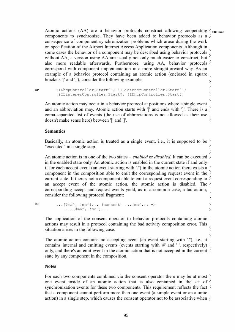
95
Atomic actions (AA) are a behavior protocols construct allowing cooperating
components to synchronize. They have been added to behavior protocols as a
consequence of component synchronization problems which arose during the work
on specification of the Airport Internet Access Application components. Although in
some cases the behavior of a component may be described using behavior protocols
without AA, a version using AA are usually not only much easier to construct, but
also more readable afterwards. Furthermore, using AA, behavior protocols
correspond with component implementation in a more straightforward way. As an
example of a behavior protocol containing an atomic action (enclosed in square
brackets '[' and ']'), consider the following example:
?IDhcpController.Start^ ; !IListenerController.Start^ ;
[?IListenerController.Start$, !IDhcpController.Start$]
An atomic action may occur in a behavior protocol at positions where a single event
and an abbreviation may. Atomic action starts with '[' and ends with ']'. There is a
coma-separated list of events (the use of abbreviations is not allowed as their use
doesn't make sense here) between '[' and ']'.
Semantics
Basically, an atomic action is treated as a single event, i.e., it is supposed to be
"executed" in a single step.
An atomic action is in one of the two states – enabled or disabled. It can be executed
in the enabled state only. An atomic action is enabled in the current state if and only
if for each accept event (an event starting with '?') in the atomic action there exists a
component in the composition able to emit the corresponding request event in the
current state. If there's not a component able to emit a request event corresponding to
an accept event of the atomic action, the atomic action is disabled. The
corresponding accept and request events yield, as in a common case, a tau action;
consider the following protocol fragment:
...[?ma^, !mc^]... (consent) ...!ma^... ->
...[#ma^, !mc^]...
The application of the consent operator to behavior protocols containing atomic
actions may result in a protocol containing the bad activity composition error. This
situation arises in the following case:
The atomic action contains no accepting event (an event starting with '?'), i.e., it
contains internal and emitting events (events starting with '#' and '!', respectively)
only, and there's an emit event in the atomic action that is not accepted in the current
state by any component in the composition.
Notes
For each two components combined via the consent operator there may be at most
one event inside of an atomic action that is also contained in the set of
synchronization events for these two components. This requirement reflects the fact
that a component cannot perform more than one event (a simple event or an atomic
action) in a single step, which causes the consent operator not to be associative when
BP
BP
CREman
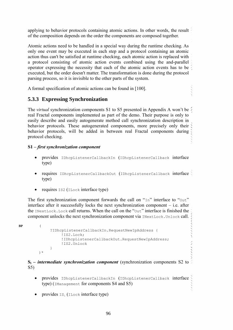
96
applying to behavior protocols containing atomic actions. In other words, the result
of the composition depends on the order the components are composed together.
Atomic actions need to be handled in a special way during the runtime checking. As
only one event may be executed in each step and a protocol containing an atomic
action thus can't be satisfied at runtime checking, each atomic action is replaced with
a protocol consisting of atomic action events combined using the and-parallel
operator expressing the necessity that each of the atomic action events has to be
executed, but the order doesn't matter. The transformation is done during the protocol
parsing process, so it is invisible to the other parts of the system.
A formal specification of atomic actions can be found in [100].
5.3.3 Expressing Synchronization
The virtual synchronization components S1 to S5 presented in Appendix A won’t be
real Fractal components implemented as part of the demo. Their purpose is only to
easily describe and easily autogenerate method call synchronization description in
behavior protocols. These autogenerated components, more precisely only their
behavior protocols, will be added in between real Fractal components during
protocol checking.
S1 – first synchronization component
provides IDhcpListenerCallbackIn (IDhcpListenerCallback interface
type)
requires IDhcpListenerCallbackOut (IDhcpListenerCallback interface
type)
requires IS2 (ILock interface type)
The first synchronization component forwards the call on “In” interface to “Out”
interface after it successfully locks the next synchronization component – i.e. after
the INextLock.Lock call returns. When the call on the “Out” interface is finished the
component unlocks the next synchronization component via INextLock.Unlock call.
(
?IDhcpListenerCallbackIn.RequestNewIpAddress {
!IS2.Lock;
!IDhcpListenerCallbackOut.RequestNewIpAddress;
!IS2.Unlock
}
)*
Si – intermediate synchronization component (synchronization components S2 to
S5)
provides IDhcpListenerCallbackIn (IDhcpListenerCallback interface
type) (IManagement for components S4 and S5)
provides ISi (ILock interface type)
BP

97
requires IDhcpListenerCallbackOut (IDhcpListenerCallback interface
type) (IManagement for components S4 and S5)
requires ISi+1 (ILock interface type)
Each of the intermediate synchronization component processes one call from
IDhcpListernerCallback (S2, S3) or IManagement (S4, S5) interfaces. If the
previous component tries to lock an intermediate component (via IPrevLock.Lock
call), it will try to lock the next component via INextLock.Lock method call. If the
component accepts call from the “In” interface either it locks the next
synchronization component and processes the call by calling the appropriate method
on the “Out” interface and then unlocks the next component; or, if it has been already
locked by the previous component, it will postpone the “Out” method call until it
accepts the IPrevLock.Unlock call. Then it calls the appropriate method on the
“Out” interface (note that the next synchronization component is still locked) and
only after this call returns it will unlock both the next component and itself (by
returning the IPrevLock.Unlock method call).
The following behavior protocol describes the S2 synchronization component.
Behavior protocols for S3 to S5 components are similar, only the
IDhcpListenerCallbackIn .RenewIpAddress and
IDhcpListenerCallbackOut.RenewIpAddress method calls are replaced by a
method name, that the synchronization component processes.
(
(
(
( ( ?IDhcpListenerCallbackIn.RenewIpAddress^;
!S3.Lock; !IDhcpListenerCallbackOut
.RenewIpAddress
) | ?S2.Lock^ )
+
( ( ( ?S2.Lock^; !S3.Lock) |
?IDhcpListenerCallbackIn.RenewIpAddress^ ) ;
!IDhcpListenerCallbackOut.RenewIpAddress )
) ;
!S2.Lock$; ?S2.Unlock^; !S3.Unlock; [!S2.Unlock$,
!IDhcpListenerCallbackIn.RenewIpAddress$]
)
+
(
?S2.Lock {!S3.Lock}; (
?IDhcpListenerCallbackIn.RenewIpAddress^ |
?S2.Unlock^ );
!IDhcpListenerCallbackOut.RenewIpAddress; !S3.Unlock;
[!S2.Unlock$, !IDhcpListenerCallbackIn
.RenewIpAddress$]
)
+
(
?S2.Lock {!S3.Lock}; ?S2.Unlock^; !S3.Unlock^; (
?IDhcpListenerCallbackIn.RenewIpAddress^ |
?S3.Unlock$ );
!S3.Lock; !IDhcpListenerCallbackOut.RenewIpAddress;
!S3.Unlock; [!S2.Unlock$,
!IDhcpListenerCallbackIn.RenewIpAddress$]
BP

98
)
+
(
?S2.Lock {!S3.Lock}; ?S2.Unlock {!S3.Unlock}
)
+
(
?IDhcpListenerCallbackIn.RenewIpAddress^; !S3.Lock;
!IDhcpListenerCallbackOut.RenewIpAddress;
!S3.Unlock^; ( ?S2.Lock^ | ?S3.Unlock$ );
!S3.Lock; !S2.Lock$; ?S2.Unlock^; !S3.Unlock;
[!S2.Unlock$, !IDhcpListenerCallbackIn
.RenewIpAddress$]
)
+
(
?IDhcpListenerCallbackIn.RenewIpAddress {!S3.Lock;
!IDhcpListenerCallbackOut.RenewIpAddress; !S3.Unlock}
)
)*
S5 – last synchronization component
provides IManagementIn (IManagement interface type)
provides IS5 (ILock interface type)
requires IManagementOut (IManagement interface type)
If the last synchronization component accepts the IManagementIn
.StopUsingPermanentIpAddresses method call it can immediately forward the call to
the “Out” interface (if it was not locked in the past). If it accepts the IPrevLock.Lock
call it will only postpone the “In” interface call until the IPrevLock.Unlock call
arrives. The behavior protocol follows:
(
(
( ?S5.Lock^ | (
?IManagementIn.StopUsingPermanentIpDatabase^;
!IManagementOut.StopUsingPermanentIpDatabase ) );
!S5.Lock$; ?S5.Unlock^; [!S5.Unlock$,
!IManagementIn.StopUsingPermanentIpDatabase$]
)
+
(
?S5.Lock; (
?IManagementIn.StopUsingPermanentIpDatabase^ |
?S5.Unlock^ );
!IManagementOut.StopUsingPermanentIpDatabase;
[!S5.Unlock$,
!IManagementIn.StopUsingPermanentIpDatabase$]
)
+
(
?S5.Lock; ?S5.Unlock
)
+
(
?IManagementIn.StopUsingPermanentIpDatabase
BP
99
{!IManagementOut.StopUsingPermanentIpDatabase}
)
)*
5.4 Dealing with Complex Error Traces
Behavior protocols [146] are a method of software component behavior
specification. They are used for behavior specification in the SOFA [161] (also in
SOFA 2 [40]) and the Fractal [34] component models. We employed behavior
protocols in several non-trivial case studies of component behavior specification,
comprising high number of components. This includes a non-trivial component-
based test bed application in a project funded by France Telecom aiming at
integration of behavior protocols into Fractal component model. One of the key
lessons learned has been that the error trace length problem is severe and has to be
addressed seriously. The goals of this paper are (i) to share with the reader the
experience gained during specifying behavior of a non-trivial component-based
application and show that the error trace length problem is really serious, and (ii) to
describe the techniques we designed to address this problem.
These goals are reflected in the rest of the Section 5.4 as follows: Section 5.4.1 and
5.4.2 illustrates how to use them for component behavior specification and
demonstrates the problem with the error trace length on a fragment of a non-trivial
application that will be used as a running example. In Section 5.4.3, as the key
contribution, the proposed techniques for addressing the error trace length and
interpretation problems are described. Section 5.4.4 contains an evaluation of the
proposed techniques while Section 9.1in related work summary chapter discusses
related work. Section 5.4.5 concludes the paper and suggests future research
direction.
5.4.1 Example: A Fragment of the Test Bed Application
In this section we describe in more detail a fragment of the demo application
described above. The application is a quite complex system allowing clients of
various air-carriers to access the Internet from airport lounges via local Wi-Fi
networks. The whole Wireless Internet Access application is composed of about 20
Fractal components. One of the key components is the DhcpServer composite
component (Figure 9). It communicates with system’s clients at the lowest level, i.e.
it is responsible for managing clients’ IP addresses, monitoring overall state of the
local wireless network and providing this information to the rest of the system. A
simplified version is presented in this section.
FACS
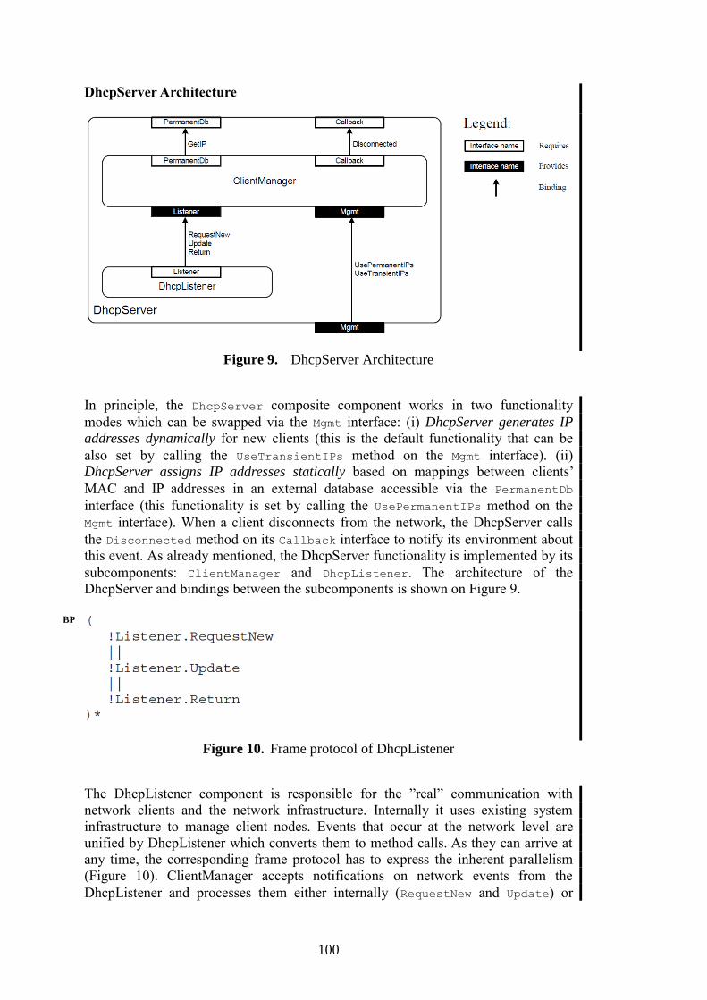
100
DhcpServer Architecture
Figure 9. DhcpServer Architecture
In principle, the DhcpServer composite component works in two functionality
modes which can be swapped via the Mgmt interface: (i) DhcpServer generates IP
addresses dynamically for new clients (this is the default functionality that can be
also set by calling the UseTransientIPs method on the Mgmt interface). (ii)
DhcpServer assigns IP addresses statically based on mappings between clients’
MAC and IP addresses in an external database accessible via the PermanentDb
interface (this functionality is set by calling the UsePermanentIPs method on the
Mgmt interface). When a client disconnects from the network, the DhcpServer calls
the Disconnected method on its Callback interface to notify its environment about
this event. As already mentioned, the DhcpServer functionality is implemented by its
subcomponents: ClientManager and DhcpListener. The architecture of the
DhcpServer and bindings between the subcomponents is shown on Figure 9.
Figure 10. Frame protocol of DhcpListener
The DhcpListener component is responsible for the ”real” communication with
network clients and the network infrastructure. Internally it uses existing system
infrastructure to manage client nodes. Events that occur at the network level are
unified by DhcpListener which converts them to method calls. As they can arrive at
any time, the corresponding frame protocol has to express the inherent parallelism
(Figure 10). ClientManager accepts notifications on network events from the
DhcpListener and processes them either internally (RequestNew and Update) or
BP

101
forwards them to DhcpServer’s environment (via Callback.Disconnected) as part
of Return processing. ClientManager’s behavior is expressed by its frame protocol
in Figure 11. The part A of the protocol represents the ”generate IP addresses
dynamically” functionality of ClientManager while the part B represents the ”assign
IP addresses statically” functionality. The parts A.1 and B.1 express the Client-
Manager’s ability to process DhcpListener’s notifications and also describe reactions
to them. The parts A.2 and B.2 capture ClientManager’s ability to detect client
disconnections internally, resulting in a call of Disconnected. The ClientManager’s
functionality mode swapping mechanism is reflected in the parts A.3 and B.3: At any
time, ClientManager can accept a method call requesting a mode change
(?Mgmt.UsePermanentIPs↑ or ?Mgmt .UseTransientIPs↑), but it does not
respond it immediately. Instead, it waits until the processing of all pending method
calls on the Listener interface is finished and then it issues the
!Mgmt.UsePermanentIPs↓ or the !Mgmt.UseTransientIPs↓ response. Then
ClientManager is again ready to accept further calls on the Listener interface and
respond to them according to its newly set functionality mode.
Figure 11. Frame protocol of ClientManager (The highlighted lines denote the
events forming the composition error described in Sect. 2.3.3)
DhcpServer Frame Protocol
The frame protocol of DhcpServer is shown in Figure 12. The interactions between
DhcpServer’s subcomponents are not visible in it. However, their communication
can trigger interaction with the environment of DhcpServer that is therefore visible in
its frame protocol. This is illustrated by the part C of the frame protocol in Figure 12:
the !Callback.Disconnected call can be invoked by the ClientManager
subcomponent either as a reaction to an accepted ?Listener.Return call or due to
its internal detection of client disconnection; however these two causes are
indistinguishable in the DhcpServer frame protocol. The part D of the protocol
expresses the DhpcServer’s ability to swap between its two modes.
BP

102
Figure 12. First version of the frame protocol of DhcpServer (Instead of +, the |
operator should have been used here as demonstrated by the error trace in Sect. 2.3.3)
5.4.2 Checking for Composition Errors and Compliance
The application developer that sets up a composite component (such as Dhcp-Server)
creates also its frame protocol, whereas the frame protocols of subcomponents
(ClientManager and DhcpListener) are created by their respective authors. It is the
developer’s responsibility to check first for composition errors (horizontal
compatibility) between subcomponents. The frame protocols ClientManager and
DhcpListener as presented above are compatible in this sense. It should be
emphasized that behavior incompatibility may occur even though the components are
connected via type-compatible interfaces.
The next step in a composite component’s development is to check for compliance
(vertical compatibility) of its frame protocol with its architecture protocol. During
the development of the first version of the DhpcServer component, the + operator
was used in its frame protocol (Figure 12). However, such a protocol was not
compliant with its architecture protocol. Using the behavior protocol checker, the
error was found and reported by an error trace (Figure 13).
BP
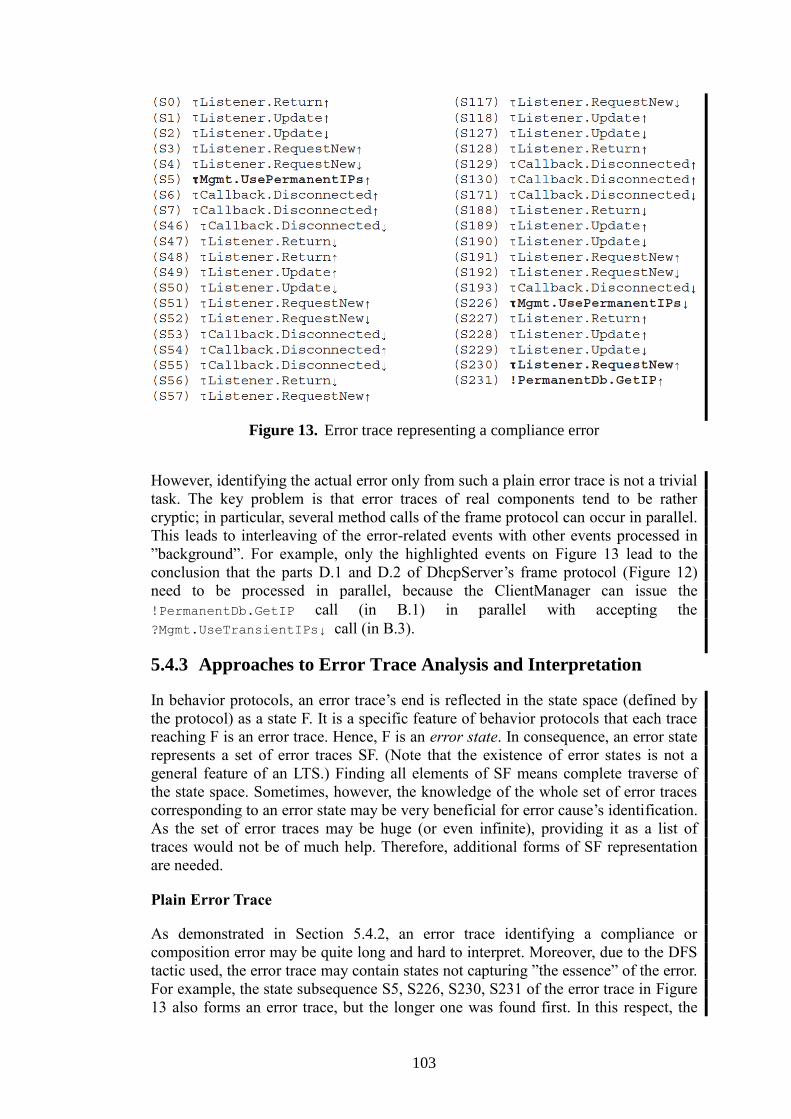
103
Figure 13. Error trace representing a compliance error
However, identifying the actual error only from such a plain error trace is not a trivial
task. The key problem is that error traces of real components tend to be rather
cryptic; in particular, several method calls of the frame protocol can occur in parallel.
This leads to interleaving of the error-related events with other events processed in
”background”. For example, only the highlighted events on Figure 13 lead to the
conclusion that the parts D.1 and D.2 of DhcpServer’s frame protocol (Figure 12)
need to be processed in parallel, because the ClientManager can issue the
!PermanentDb.GetIP call (in B.1) in parallel with accepting the
?Mgmt.UseTransientIPs↓ call (in B.3).
5.4.3 Approaches to Error Trace Analysis and Interpretation
In behavior protocols, an error trace’s end is reflected in the state space (defined by
the protocol) as a state F. It is a specific feature of behavior protocols that each trace
reaching F is an error trace. Hence, F is an error state. In consequence, an error state
represents a set of error traces SF. (Note that the existence of error states is not a
general feature of an LTS.) Finding all elements of SF means complete traverse of
the state space. Sometimes, however, the knowledge of the whole set of error traces
corresponding to an error state may be very beneficial for error cause’s identification.
As the set of error traces may be huge (or even infinite), providing it as a list of
traces would not be of much help. Therefore, additional forms of SF representation
are needed.
Plain Error Trace
As demonstrated in Section 5.4.2, an error trace identifying a compliance or
composition error may be quite long and hard to interpret. Moreover, due to the DFS
tactic used, the error trace may contain states not capturing ”the essence” of the error.
For example, the state subsequence S5, S226, S230, S231 of the error trace in Figure
13 also forms an error trace, but the longer one was found first. In this respect, the

104
other states are “not-important” ones. It is a challenge to filter out these “not-
important” states (to find a canonical representation of the error trace set associated
with an error state). One can imagine a filtering technique based on iterative re-
searching the state space, which would take advantage of the knowledge of the depth
at which the error was found.
State Space Visualization
One of the checking outputs we propose in order to make error interpretation easier
is state space visualization. Visualization is a graphical representation of the state
space associated with the protocol. For the state space related to Section 5.4.1
(DhcpServer architecture), this is illustrated on Figure 14 (only a fragment of the
state space is captured here for brevity). This helps find out what the problem cause
is by tracking the error trace in the state space. Apparently, state space size might be
a problem here — a state space having more than 1,000 states is hard to visualize.
Thus, visualizing only a part of the state space becomes a practical necessity. In this
perspective, capturing only the part containing the error state and its “neighborhood”
is a straightforward thought. We employed this idea with a very positive experience.
Such a result still provides useful information, detailed enough to identify where the
essence of an error is. Technically, our visualization outputs all the transitions leading
from a state on the error trace — this helps with finding correspondence with the
original protocol.
Figure 14. State space visualization — dashed lines represent longer paths omitted
due to the limited space of this paper. The state S231 is the error state F.
Protocol Annotation
Another way of representing an error state are annotated protocols. Consider a
composition of protocols P and Q via the consent operator. If the composition yields
a composition error in an error state S, the state S is represented by marks <HERE>
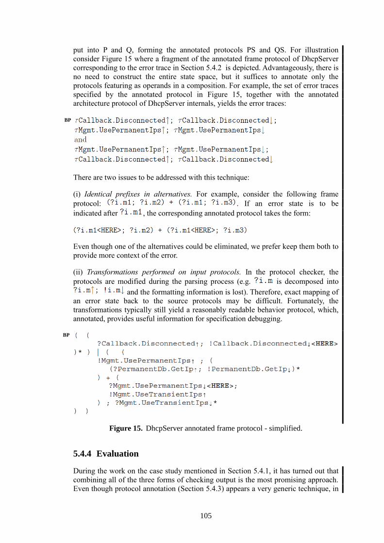
105
put into P and Q, forming the annotated protocols PS and QS. For illustration
consider Figure 15 where a fragment of the annotated frame protocol of DhcpServer
corresponding to the error trace in Section 5.4.2 is depicted. Advantageously, there is
no need to construct the entire state space, but it suffices to annotate only the
protocols featuring as operands in a composition. For example, the set of error traces
specified by the annotated protocol in Figure 15, together with the annotated
architecture protocol of DhcpServer internals, yields the error traces:
There are two issues to be addressed with this technique:
(i) Identical prefixes in alternatives. For example, consider the following frame
protocol: . If an error state is to be
indicated after , the corresponding annotated protocol takes the form:
Even though one of the alternatives could be eliminated, we prefer keep them both to
provide more context of the error.
(ii) Transformations performed on input protocols. In the protocol checker, the
protocols are modified during the parsing process (e.g. is decomposed into
and the formatting information is lost). Therefore, exact mapping of
an error state back to the source protocols may be difficult. Fortunately, the
transformations typically still yield a reasonably readable behavior protocol, which,
annotated, provides useful information for specification debugging.
Figure 15. DhcpServer annotated frame protocol - simplified.
5.4.4 Evaluation
During the work on the case study mentioned in Section 5.4.1, it has turned out that
combining all of the three forms of checking output is the most promising approach.
Even though protocol annotation (Section 5.4.3) appears a very generic technique, in
BP
BP
106
complex cases the other checking outputs have to be also provided, since tracking all
the path alternatives in an annotated complex protocol may be error-prone.
The most complex components of the case study have behavior protocols with up to
60 events; such behavior protocols generate a state space with hundreds of thousands
of states. The typical errors encountered during the development of such components
then generate error traces of about 100 states in length. However there were also
some error states that generated error traces with several hundreds of states. It then
took the developer about an hour (often even more) to identify the actual error in
case only a plain error trace was available. The checking output techniques presented
in Section 5.4.3 have been developed to improve debugging efficiency. During the
further development of our case study application, the developers used a combination
of these techniques and an average time to resolve a typical error shortened down to
one third or one fourth of the original time. As for the plain error trace checking
output, a problem is the existence of “local loops” in behavior of a component.
Typically, with respect to the other parts of the system, the actual number of local
loop traversals is of no significance in terms of error localization. These loops
lengthen the error trace, making it more complex and hard to analyze. Apparently, if
loops are nested, the situation is even worse. A desire is to eliminate those of “no
influence” on the rest of the system. This is a challenging problem - currently, only
the highest-level loops are identified and eliminated in an automated way. Annotated
protocols are very similar to the approach used in Bandera Toolset [155] and PREfast
[121] since they are based on emphasizing of the positions in the input protocols
where a composition error has been found. Unlike in Bandera and PREfast, in
behavior protocols the positions between two operations are highlighted to denote an
error state.
5.4.5 Conclusion and Future Work
During the work on the project (Chapter 5) it has turned out that, besides plain error
trace, additional checking outputs are needed for speeding up error detecting and
debugging process. Therefore, we introduced two more approaches: (i) state space
visualization, and (ii) annotated protocols. Using all the three methods in
combination was found most beneficial (locating an error was then more efficient).
Problems arise when checking the composition/compliance of several components
described by really complex behavior protocols. The large state space generated by
such a protocol causes that an error trace is typically very long and hard to interpret.
Still, in our view, this is worth to pursue since we believe that the components’
compatibility problem cannot be restricted to the syntactic/type compatibility of their
(bounded) interfaces [146], even though this could be checked with much smaller
effort and would avoid the problems discussed in this paper; in fact, we can hardly
imagine putting together a non-trivial component-based application of the size
mentioned in Section 5.4.1, if the compliance checks were based only on
syntactic/type compatibility of individual interfaces. Our future work is therefore
focused on improving the methods currently used by the behavior protocol checker;
in particular, a method for automated removing of unnecessary ”local loops” (Section
5.4.4) would further simplify the plain error trace checking output. As for state space
visualization, an automated method for detecting the ”important” part of the state
space (currently done by hand) is needed to simplify the resulting graphical
representation of an error trace. Similar to Bandera [155] and PREfast [121], the

107
possibility to dynamically indicate the correspondence between a particular position
in an error trace and the associated part of the protocol would perhaps further ease
and speed up the debugging process.
108
Chapter 6 CoCoME Case-study
In this chapter we present our approach and experience of modeling the CoCoME
case-study [82] in Fractal component model and its implementation in Fractal’s Julia
runtime and tool-chain. The CoCoME case-study was prepared for the CoCoME
modeling contest [151][55] that aimed at comparison of contemporary component-
oriented modeling approaches.
6.1 Modeling the CoCoME in Fractal
Employing Fractal in the CoCoME assignment revealed several issues that required
modifications of the architecture. These modifications are presented and justified in
Section 6.1.1 (Static view). Since behavior specification using Behavior Protocols is
supported by Fractal, each of the components of the Trading System was annotated
with its frame protocol. As CoCoME assignment does not include complete behavior
specification, these protocols are created based on the CoCoME UML specification
and the reference implementation and further described in Section 6.1.2 (Behavioral
view). Section 6.1.4 (Deployment view) presents deployment and distribution using
Fractal-specific means (FractalRMI and FractalADL). In Section 6.1.5
(Implementation view), we describe beside the basic Fractal implementation strategy
also the details related to performance evaluation and estimation. Additionally,
Section 6.1.3 presents behavior specification of two components featuring non-trivial
behavior (CashDeskApplication and CeshDeskBus) in more detail. Behavior
specification of the rest of the components can be found on the Fractal-CoCoME web
page [71].
6.1.1 Static View
As the architecture of the Trading System used in Fractal differs slightly from the
CoCoME assignment, this section presents the modified architecture and justifies the
modifications made. In general, there are two sorts of modifications: (i)
Modifications which are not directly related to Fractal and do not influence
complexity of the solution, but rather contribute to the clarity of the design and the
other views (in Sections 6.1.2 – 6.1.5). (ii) Modifications directly forced by specific
properties of Fractal. These modifications reveal strengths and limitations of Fractal
and therefore should be taken into account in the comparison between different
modeling approaches.
The (i) modifications include reorganization of the component hierarchy and explicit
partitioning of EventBus into two independent buses. All primitive components are
left unchanged, but the composed components GUI and Application located in the
Inventory component are substituted by components StoreApplication,
ReportingApplication (compare Figure 16 and Figure 18). The new components
more clearly encapsulate the logical units featuring orthogonal functionality, whereas
the old ones merely present a general three tier architecture. The StoreApplication
component encapsulates the store functionality as required by the CashDeskLine
CoCoME
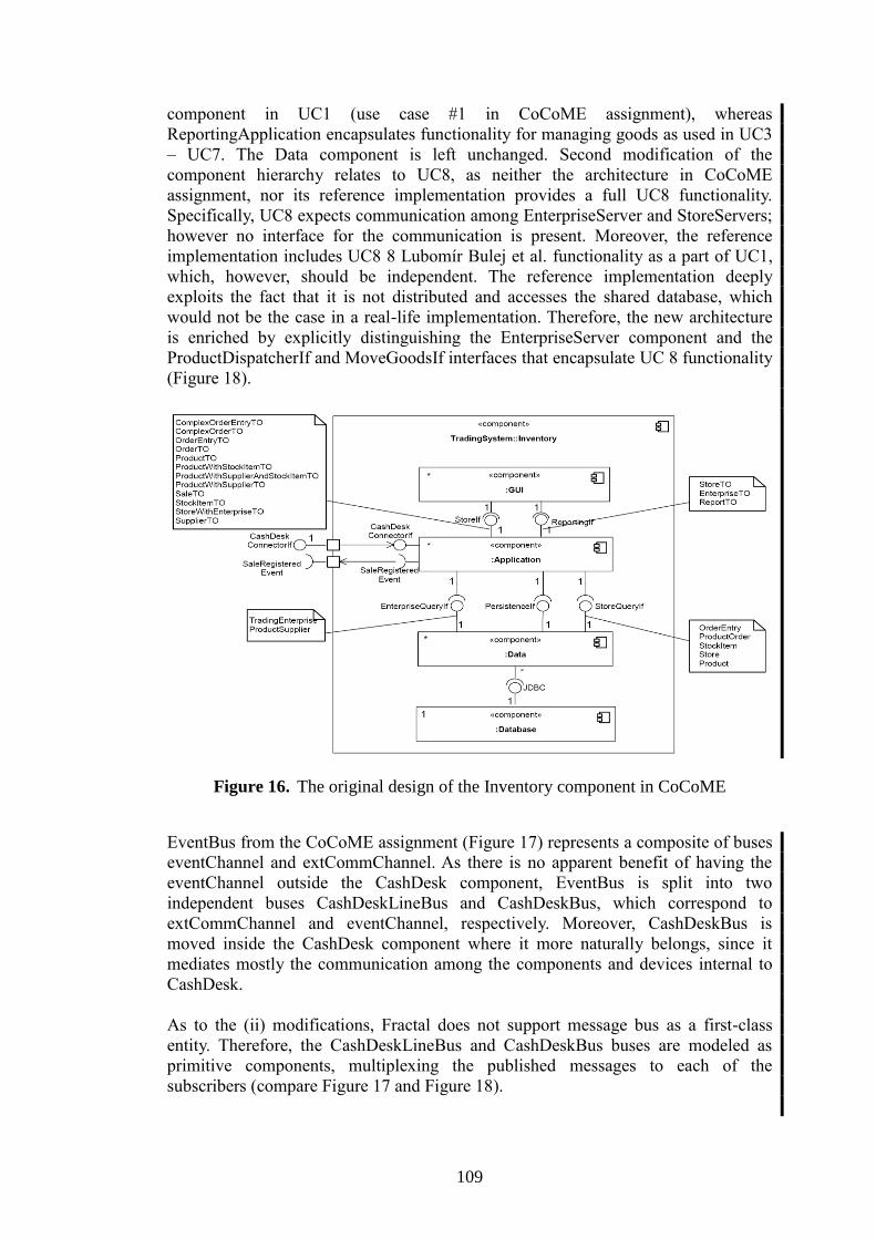
109
component in UC1 (use case #1 in CoCoME assignment), whereas
ReportingApplication encapsulates functionality for managing goods as used in UC3
– UC7. The Data component is left unchanged. Second modification of the
component hierarchy relates to UC8, as neither the architecture in CoCoME
assignment, nor its reference implementation provides a full UC8 functionality.
Specifically, UC8 expects communication among EnterpriseServer and StoreServers;
however no interface for the communication is present. Moreover, the reference
implementation includes UC8 8 Lubomír Bulej et al. functionality as a part of UC1,
which, however, should be independent. The reference implementation deeply
exploits the fact that it is not distributed and accesses the shared database, which
would not be the case in a real-life implementation. Therefore, the new architecture
is enriched by explicitly distinguishing the EnterpriseServer component and the
ProductDispatcherIf and MoveGoodsIf interfaces that encapsulate UC 8 functionality
(Figure 18).
Figure 16. The original design of the Inventory component in CoCoME
EventBus from the CoCoME assignment (Figure 17) represents a composite of buses
eventChannel and extCommChannel. As there is no apparent benefit of having the
eventChannel outside the CashDesk component, EventBus is split into two
independent buses CashDeskLineBus and CashDeskBus, which correspond to
extCommChannel and eventChannel, respectively. Moreover, CashDeskBus is
moved inside the CashDesk component where it more naturally belongs, since it
mediates mostly the communication among the components and devices internal to
CashDesk.
As to the (ii) modifications, Fractal does not support message bus as a first-class
entity. Therefore, the CashDeskLineBus and CashDeskBus buses are modeled as
primitive components, multiplexing the published messages to each of the
subscribers (compare Figure 17 and Figure 18).

110
Despite the modifications made, many parts of the original design and prototype
implementation are adopted even when “unrealistic”, such as the CardReader
component communicating with Bank through CashDeskApplication instead of
directly, which presents a security threat with PIN code interception possibility. In
order to share as much of the CoCoME assignment as possible, other parts of the
design such as the data model and the transfer objects are left unmodified. The
Fractal implementation is designed to use Hibernate and Derby database for
persistency as is the case with the prototype implementation.
Figure 17. The original design of the CashDeskLine component in CoCoME
6.1.2 Behavioral View – Modeling CoCoME in General
The behavior protocols describing application’s behavior are meant to be part of the
specification of the application. Created at the application design stage, they allow
developers to verify that the implementation is compliant with the design, or, in other
words, that it really implements the specification. However, as the behavior protocols
were not part of the specification of the CoCoME assignment, they had to be
recreated from the description provided in it.
The provided specification contains only sequence diagrams and use-cases, which do
not provide as precise and unambiguous specification of the application’s behavior as
it is required to formally verify the resulting implementation correctness (in order to
be sufficient, the specification would have to include more complete UML
description, like collaboration and activity diagrams or state machines). For this
reason, we had to use the reference implementation provided also as a part of the
specification and use both the UML descriptions and the reference implementation to
create the behavior protocols for the application. A problem has however arisen
during the behavior protocol development process – we found that the reference
implementation is not fully compliant with the CoCoME UML specification as
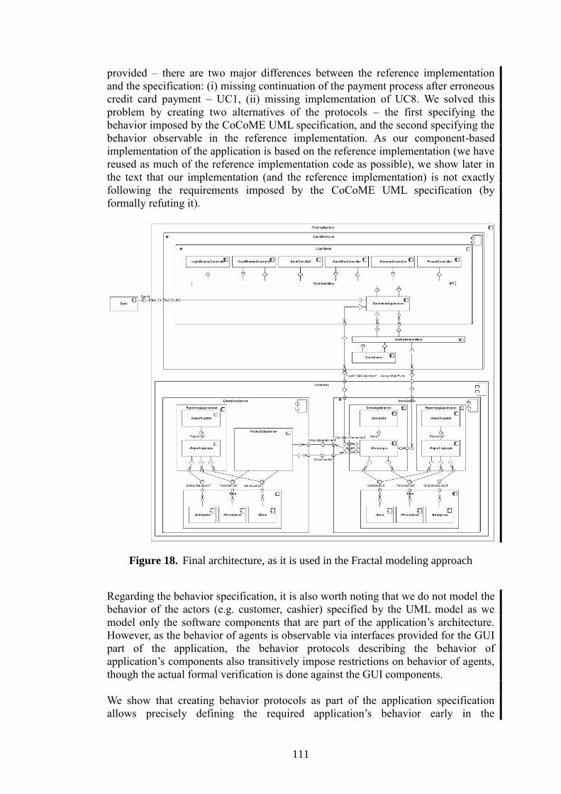
111
provided – there are two major differences between the reference implementation
and the specification: (i) missing continuation of the payment process after erroneous
credit card payment – UC1, (ii) missing implementation of UC8. We solved this
problem by creating two alternatives of the protocols – the first specifying the
behavior imposed by the CoCoME UML specification, and the second specifying the
behavior observable in the reference implementation. As our component-based
implementation of the application is based on the reference implementation (we have
reused as much of the reference implementation code as possible), we show later in
the text that our implementation (and the reference implementation) is not exactly
following the requirements imposed by the CoCoME UML specification (by
formally refuting it).
Figure 18. Final architecture, as it is used in the Fractal modeling approach
Regarding the behavior specification, it is also worth noting that we do not model the
behavior of the actors (e.g. customer, cashier) specified by the UML model as we
model only the software components that are part of the application’s architecture.
However, as the behavior of agents is observable via interfaces provided for the GUI
part of the application, the behavior protocols describing the behavior of
application’s components also transitively impose restrictions on behavior of agents,
though the actual formal verification is done against the GUI components.
We show that creating behavior protocols as part of the application specification
allows precisely defining the required application’s behavior early in the
112
development process (in the application design stage). Such specification then
provides not only the global view that is required to correctly create the application’s
architecture, but also a per component behavioral view that can serve as a precise
guide for developers of specific component implementations. Furthermore, the
specification can be used to formally verify that the implementation really complies
with the specification requirements and that all the application components (although
each might be implemented by a different developer) are compatible and together
provide the functionality (exposed by their behavior) required by the specification.
6.1.3 Behavioral View – Specification of Selected Components
This section is mostly focused on behavioral view of CoCoMe components. More
specifically, it assumes that the specification of component structure, interfaces, and
overall architecture is taken over from the CoCoMe assignment with the few
modification mentioned in Section 6.1.1. As emphasized in Section 6.1.2, the
behavior specification provided here is done in behavior protocols and stems from
the CoCoMe use cases and the component behavior encoded in the Java
implementation provided in the CoCoMe assignment. Since the behavior
specification of the whole application is too large to fit into space reserved for this
chapter, two “interesting” components (Cash-DeskApplication and CashDeskBus)
were chosen to demonstrate the capabilities of behavior protocols. Interested reader
may find the specification of other “interesting” components in the appendix and full
specification at [71].
Demonstrating the ordinary usage of this formalism, the behavior protocol of
CashDeskApplication describes the actual behavior of a cash desk. In principle, it
captures the state machine corresponding to the sale process. In contrast, the
behavior protocol of CashDeskBus illustrates the specific way of expressing mutual
exclusion.
Since both these protocols are non-trivial, their “uninteresting” fragments are omitted
in this section.
CashDeskApplication
The CashDeskApplication has application specific behavior – its frame protocol
reflects the state of the current sale. It indicates what actions a cash desk allows the
cashier to perform in a specific current sale state. The “interesting” parts of the
protocol take the following form.
(
# INITIALISED
(
?CashDeskApplicationHandler.onSaleStarted
);
# SALE_STARTED
(
?CashDeskApplicationHandler.onProductBarcodeScanned{
!CashDeskConnector.getProductWithStockItem;
!CashDeskApplicationDispatcher.sendProductBarcodeNotValid+
!CashDeskApplicationDispatcher.sendRunningTotalChanged
}
BP
113
)*; # <--- LOOP
?CashDeskApplicationHandler.onSaleFinished;
# SALE_FINISHED
(
?CashDeskApplicationHandler.onPaymentMode
);
# PAYING_BY_CASH
(
(
(
?CashDeskApplicationHandler.onCashAmountEntered
)*;
# On Enter
?CashDeskApplicationHandler.onCashAmountCompleted{
!CashDeskApplicationDispatcher
.sendChangeAmountCalculated
};
?CashDeskApplicationHandler.onCashBoxClosed{
!CashDeskApplicationDispatcher.sendSaleSuccess;
!CDLEventDispatcher.sendAccountSale;
!CDLEventDispatcher.sendSaleRegistered
}
)
)
)* | (
# Enable Express Mode
?CDLEventHandler.onExpressModeEnabled{
!CashDeskApplicationDispatcher.sendExpressModeEnabled
}
)* | (
# Disable Express Mode
?CashDeskApplicationHandler.onExpressModeDisabled
)*
To communicate with each of the buses CashDeskBus and CashDeskLineBus, the
component features a pair of interfaces (CashDeskApplicationHandler,
CashDeskApplicationDispatcher and CDLEventHandler, CDLEventDispatcher). The
interfaces contain a specific method for each event type that can occur on a bus. In
addition, the interface, CashDeskInterface serves to get the data from Inventory.
The protocol specifies three parallel activities. The first one is the sale process itself,
while the other two deal with cash desk mode switching. In the initial state, the sale
process activity is waiting for SaleStartedEvent on the CashDeskBus (?Cash-
DeskApplicationHandler.onSaleStarted). It denotes beginning of a new sale.
Then (; operator) BarcodeScannedEvent is accepted (?CashDeskApplication-
Handler.onProductBarcodeScanned) for each sale item. Repetition operator (*)
ensures that arbitrary finite number of events can be accepted. In reaction (the
expression enclosed in {}) to each BarcodeScannedEvent, the price is obtained from
Inventory. (!CashDeskConnector.getProductWithStockItem) . Depending on
the result, the rest of the CashDesk is informed about the change of total sale price
(!Cash-DeskApplicationDispatcher.sendRunningTotalChanged) or,
alternatively (+ operator), ProductBarcodeNotValidEvent is issued
(!CashDeskApplication-Dispatcher.sendProductBarcodeNotValid). When
SaleFinishedEvent is accepted (?CashDeskApplicationHandler
.onSaleFinished), the sale process reaches the payment phase which is specified
in similar manner. When one sale is finished, the sale process activity returns to the
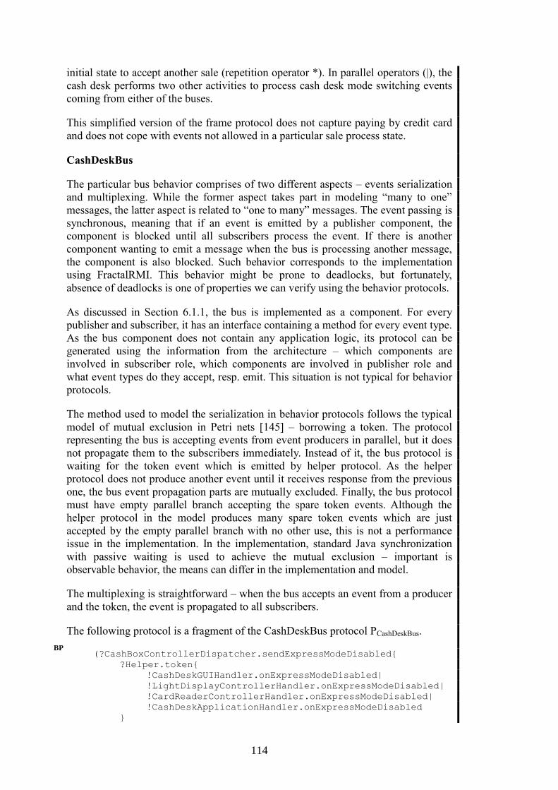
114
initial state to accept another sale (repetition operator *). In parallel operators (|), the
cash desk performs two other activities to process cash desk mode switching events
coming from either of the buses.
This simplified version of the frame protocol does not capture paying by credit card
and does not cope with events not allowed in a particular sale process state.
CashDeskBus
The particular bus behavior comprises of two different aspects – events serialization
and multiplexing. While the former aspect takes part in modeling “many to one”
messages, the latter aspect is related to “one to many” messages. The event passing is
synchronous, meaning that if an event is emitted by a publisher component, the
component is blocked until all subscribers process the event. If there is another
component wanting to emit a message when the bus is processing another message,
the component is also blocked. Such behavior corresponds to the implementation
using FractalRMI. This behavior might be prone to deadlocks, but fortunately,
absence of deadlocks is one of properties we can verify using the behavior protocols.
As discussed in Section 6.1.1, the bus is implemented as a component. For every
publisher and subscriber, it has an interface containing a method for every event type.
As the bus component does not contain any application logic, its protocol can be
generated using the information from the architecture – which components are
involved in subscriber role, which components are involved in publisher role and
what event types do they accept, resp. emit. This situation is not typical for behavior
protocols.
The method used to model the serialization in behavior protocols follows the typical
model of mutual exclusion in Petri nets [145] – borrowing a token. The protocol
representing the bus is accepting events from event producers in parallel, but it does
not propagate them to the subscribers immediately. Instead of it, the bus protocol is
waiting for the token event which is emitted by helper protocol. As the helper
protocol does not produce another event until it receives response from the previous
one, the bus event propagation parts are mutually excluded. Finally, the bus protocol
must have empty parallel branch accepting the spare token events. Although the
helper protocol in the model produces many spare token events which are just
accepted by the empty parallel branch with no other use, this is not a performance
issue in the implementation. In the implementation, standard Java synchronization
with passive waiting is used to achieve the mutual exclusion – important is
observable behavior, the means can differ in the implementation and model.
The multiplexing is straightforward – when the bus accepts an event from a producer
and the token, the event is propagated to all subscribers.
The following protocol is a fragment of the CashDeskBus protocol PCashDeskBus.
(?CashBoxControllerDispatcher.sendExpressModeDisabled{
?Helper.token{
!CashDeskGUIHandler.onExpressModeDisabled|
!LightDisplayControllerHandler.onExpressModeDisabled|
!CardReaderControllerHandler.onExpressModeDisabled|
!CashDeskApplicationHandler.onExpressModeDisabled
}
BP
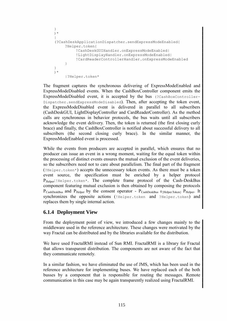
115
}
)*
|
(?CashDeskApplicationDispatcher.sendExpressModeEnabled{
?Helper.token{
!CashDeskGUIHandler.onExpressModeEnabled|
!LightDisplayHandler.onExpressModeEnabled|
!CardReaderControllerHandler.onExpressModeEnabled
}
}
)*
|?Helper.token*
The fragment captures the synchronous delivering of ExpressModeEnabled and
ExpressModeDisabled events. When the CashBoxController component emits the
ExpressModeDisabled event, it is accepted by the bus (?CashBoxController-
Dispatcher.sendExpressModeDisabled). Then, after accepting the token event,
the ExpressModeDisabled event is delivered in parallel to all subscribers
(CashDeskGUI, LightDisplayController and CardReaderController). As the method
calls are synchronous in behavior protocols, the bus waits until all subscribers
acknowledge the event delivery. Then, the token is returned (the first closing curly
brace) and finally, the CashBoxController is notified about successful delivery to all
subscribers (the second closing curly brace). In the similar manner, the
ExpressModeEnabled event is processed.
While the events from producers are accepted in parallel, which ensures that no
producer can issue an event in a wrong moment, waiting for the equal token within
the processing of distinct events ensures the mutual exclusion of the event deliveries,
so the subscribers need not to care about parallelism. The final part of the fragment
(?Helper.token*) accepts the unnecessary token events. As there must be a token
event source, the specification must be enriched by a helper protocol
PHelper:!Helper.token*. The complete frame protocol of the Cash-DeskBus
component featuring mutual exclusion is then obtained by composing the protocols
PCashDeskBus and PHelper by the consent operator - PCashDeskBus ∇{Helper.Token} PHelper. It
synchronizes the opposite actions (!Helper.token and ?Helper.token) and
replaces them by single internal action.
6.1.4 Deployment View
From the deployment point of view, we introduced a few changes mainly to the
middleware used in the reference architecture. These changes were motivated by the
way Fractal can be distributed and by the libraries available for the distribution.
We have used FractalRMI instead of Sun RMI. FractalRMI is a library for Fractal
that allows transparent distribution. The components are not aware of the fact that
they communicate remotely.
In a similar fashion, we have eliminated the use of JMS, which has been used in the
reference architecture for implementing buses. We have replaced each of the both
busses by a component that is responsible for routing the messages. Remote
communication in this case may be again transparently realized using FractalRMI.
116
The Fractal specification also lays out another way of solving distribution and
various communication styles. It defines so called composite bindings. Each
composite binding consists of a number of binding components. These components
are classical components from the Fractal point of view, their responsibilities are to
encapsulate or implement middleware. A significant help in implementing the
composite bindings is provided by the Dream framework, which implements Fractal
components that support construction of communication middleware with various
communication styles, including JMS.
Our choice of FractalRMI is transparent and requires no additional implementation
effort. We did not use the composite bindings and Dream also because Dream is still
under development; additionally, our solution brings no restrictions to the modeled
CoCoME example.
Another important aspect of deployment is the way deployment is planned and
performed. In our approach, we have put the information about deployment into
FractalADL. Each specified component is annotated with an element virtual-node
which states the deployment node to which the component is to be deployed. The
actual distribution is then realized via FractalRMI.
6.1.5 Implementation View
The Fractal implementation is based both on the Fractal architecture model of the
application and the provided reference implementation. We have created a
FractalADL model of the application architecture using the FractalGUI modeling
tool [73], taking into account the changes mentioned in Section 6.1.4. The resulting
model was then extended by hand to accommodate behavior protocol specification,
because it is not supported by the modeling tool.
To speed up and simplify the development, we have used a tool to create component
skeletons from the architecture model. More detailed description of the
transformation can be found in Sect. 4. The functional part of the application was
then adapted from the CoCoME reference implementation and integrated into the
generated component skeletons.
6.1.5.1 Testing the Implementation against Use-case Scenarios
To enable the testing of functional properties specified by behavior protocols,
FractalBPC allows monitoring communication on the interfaces of a component C
when the application is running. The runtime checker integrated in FractalBPC
automatically tests whether C communicates with other components in a way that is
allowed by C’s frame protocol. Any violation of the frame protocol by C or one of
the components communicating with C is reported.
In addition, the reference implementation of the trading system contains a small test
suite for testing the behavior of the implementation against the use case scenarios
described in the CoCoME assignment. The test suite, based on the jUnit [97]
framework, contains a number of tests which exercise operations prescribed by the
respective use cases and verify that the system responds accordingly.

117
As it is, however, the test suite from the reference implementation is unsuitable for
testing. The key issues are testing of crosscutting concerns, test design, and
insufficient automation.
The tests attempt to verify not only that the implementation functions correctly, but
also impose timing constraints on the executed operations. This makes the tests
unreliable, because two orthogonal aspects are tested at the same time. Combined
with rather immodest resource requirements of the application arising from the use of
“heavy-duty” middleware packages for database functionality, persistence, and
message-based communication, the application often fails to meet the test deadlines
on common desktop hardware, even though it functions correctly.
Moreover, the tests always expect to find the trading system in a specific state, which
is a very strong requirement. To accommodate it, all the applications comprising the
trading system are restarted and the database is reinitialized after each test run, which
adds extreme overhead to the testing process.
This is further exacerbated by insufficient automation of the testing infrastructure.
The trading system consists of a number of components, such as the enterprise server
and clients, store server and clients, database server, etc. Starting the trading system
is a long and complicated process, which can take several minutes in the best case,
and fail due to insufficient synchronization between parts of the system in the worst
case. Manual starting of the trading system, combined with the need for restarting the
system after each test run, makes the test suite in its present form unusable.
To enable testing in a reasonably small environment, we take the following steps to
eliminate or mitigate the key issues, leading to a considerable increase in the
reliability of the tests as well as reduced testing time:
We simplify the implementation of the trading system by eliminating the GUI
components, leaving just the business functionality, which allows the trading
system to be operated in headless mode.
We eliminate the validation of extra-functional properties from testing; timing
properties of the trading system are gathered at runtime by a monitoring
infrastructure. Validation of extra-functional system properties is independent
from functional testing and is based on the data obtained during monitoring.
We improve the testing infrastructure by automating the start of the trading
system. This required identifying essential and unnecessary code paths and
fixing synchronization issues between various parts of the system.
6.2 Tools and Results of Verification
Verification of an application consists of two steps. First step is checking the
protocols compliance. Protocols of all components used to implement a composite
component are checked against the frame protocol of the composite component.
Second step is checking whether the implementation of the primitive components
correspond to their protocols.
Compliance of the whole Trading System was checked using the dChecker [57] tool
with positive result. The dChecker tool is based on translation of the protocols into
minimized finite state machines. Then, composite state space is generated on the fly
118
to discover a potential bad activity error or deadlock. Moreover, in order to fight the
state explosion problem, dChecker supports both parallel and distributed verification,
so that the full computational power of multiprocessor and multicomputer systems is
exploited. For illustration, correctness of the whole architecture takes 192 seconds to
be verified on a 2xDualCore at 2.3GHz with 4GB RAM PC. Specifically, the
protocol of CashDeskApplication is translated into finite state machine consisting of
944 states. The composite state space of CashDesk features 398029 states and it takes
8 seconds to be verified (on the same PC).
Correspondence of the implementation of primitive components to their frame
protocols is verified by the Java PathFinder (JPF) model checker. Since JPF, by
default, checks only low level properties like deadlocks and uncaught exceptions, we
use JPF in combination with the behavior protocol checker (BPC) [144]. Component
environment is represented by a set of Java classes that are constructed in a
semiautomated way: (i) The EnvGen tool (Environment Generator for JPF) is used to
generate the classes according to the behavior specification of the environment via
the component’s inverted frame protocol, and (ii) the generated classes are manually
modified if the environment has to respect data-flow and the component's state in
order to behave correctly (original behavior protocols do not model data and
component's state explicitly).
By code checking implementation of the CashDeskApplication against the frame
protocol created according to the reference specification of UC1, we were able to
detect the inconsistency between the reference implementation and specification of
UC1 that is first mentioned in Sect 3.2. Detection of this inconsistency took 2
seconds on a 2xDualCore at 2.3GHz with 4 GB RAM PC. Code checking of the
implementation of CashDeskApplication against the frame protocol created
according to the reference implementation has not reported any error and took 14
seconds. Nevertheless, switching between the express and normal mode is not
checked, since the environment is not able to find whether the application is in the
express mode or not, and thus it does not know whether it can trigger payment by
credit card (forbidden in the express mode). Moreover, we also had to introduce the
CashAmountCompleted event into the frame protocol and implementation of
CashDeskApplication. This change was motivated by the need to explicitly denote
the moment when the cash amount is completely specified (originally, the
CashAmountEntered event with a specific value of its argument was used for this
purpose). Were the CashAmountCompleted event not added, the environment for
CashDeskApplication would exercise the component in such a way that a spurious
violation of its frame protocol would be reported by JPF.
As for run-time checking, the special version of BPC is used again. The difference is
that notification is not performed by JPF, but by runtime interceptors of method calls
on component’s external interfaces; moreover, no backtracking in BPC is needed
since only a single run of the application is checked.
When using the tools, however, the state explosion problem became an issue. Some
of the behavior protocols (namely CashDeskBus and Data) originally featured
prohibitively large state space. Thus, in order to fight the state explosion problem,
heuristics were employed. First, CashDeskBus protocol is separated into multiple
protocols (as if for multiple components), so that it can be represented by multiple

119
smaller finite state machines in contrast to a single unfeasibly large state machine.
Second, method calls inside behavior protocol of the Data component are explicitly
annotated by the thread number. This is again in order to the fight state explosion as
this makes the protocol more deterministic while preserving the same level of
parallelism. For these reasons, protocols on the CoCoME Fractal web page differ
from the protocols described in here, as they include also the heuristics.
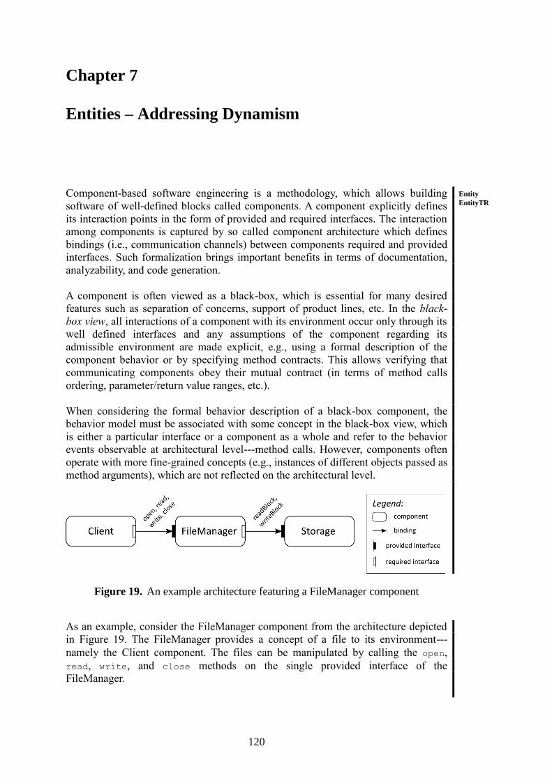
120
Chapter 7
Entities – Addressing Dynamism
Component-based software engineering is a methodology, which allows building
software of well-defined blocks called components. A component explicitly defines
its interaction points in the form of provided and required interfaces. The interaction
among components is captured by so called component architecture which defines
bindings (i.e., communication channels) between components required and provided
interfaces. Such formalization brings important benefits in terms of documentation,
analyzability, and code generation.
A component is often viewed as a black-box, which is essential for many desired
features such as separation of concerns, support of product lines, etc. In the black-
box view, all interactions of a component with its environment occur only through its
well defined interfaces and any assumptions of the component regarding its
admissible environment are made explicit, e.g., using a formal description of the
component behavior or by specifying method contracts. This allows verifying that
communicating components obey their mutual contract (in terms of method calls
ordering, parameter/return value ranges, etc.).
When considering the formal behavior description of a black-box component, the
behavior model must be associated with some concept in the black-box view, which
is either a particular interface or a component as a whole and refer to the behavior
events observable at architectural level---method calls. However, components often
operate with more fine-grained concepts (e.g., instances of different objects passed as
method arguments), which are not reflected on the architectural level.
Figure 19. An example architecture featuring a FileManager component
As an example, consider the FileManager component from the architecture depicted
in Figure 19. The FileManager provides a concept of a file to its environment---
namely the Client component. The files can be manipulated by calling the open,
read, write, and close methods on the single provided interface of the
FileManager.
Entity
EntityTR
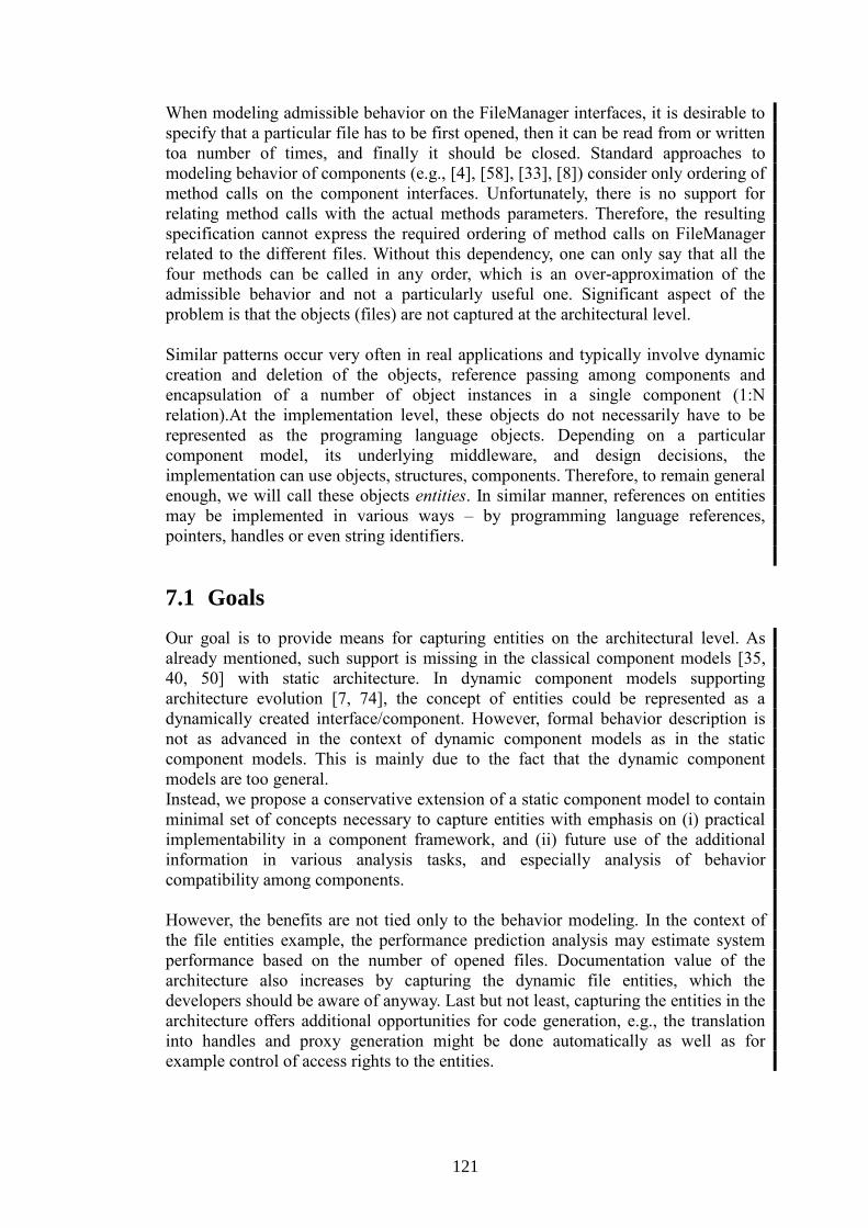
121
When modeling admissible behavior on the FileManager interfaces, it is desirable to
specify that a particular file has to be first opened, then it can be read from or written
toa number of times, and finally it should be closed. Standard approaches to
modeling behavior of components (e.g., [4], [58], [33], [8]) consider only ordering of
method calls on the component interfaces. Unfortunately, there is no support for
relating method calls with the actual methods parameters. Therefore, the resulting
specification cannot express the required ordering of method calls on FileManager
related to the different files. Without this dependency, one can only say that all the
four methods can be called in any order, which is an over-approximation of the
admissible behavior and not a particularly useful one. Significant aspect of the
problem is that the objects (files) are not captured at the architectural level.
Similar patterns occur very often in real applications and typically involve dynamic
creation and deletion of the objects, reference passing among components and
encapsulation of a number of object instances in a single component (1:N
relation).At the implementation level, these objects do not necessarily have to be
represented as the programing language objects. Depending on a particular
component model, its underlying middleware, and design decisions, the
implementation can use objects, structures, components. Therefore, to remain general
enough, we will call these objects entities. In similar manner, references on entities
may be implemented in various ways – by programming language references,
pointers, handles or even string identifiers.
7.1 Goals
Our goal is to provide means for capturing entities on the architectural level. As
already mentioned, such support is missing in the classical component models [35,
40, 50] with static architecture. In dynamic component models supporting
architecture evolution [7, 74], the concept of entities could be represented as a
dynamically created interface/component. However, formal behavior description is
not as advanced in the context of dynamic component models as in the static
component models. This is mainly due to the fact that the dynamic component
models are too general.
Instead, we propose a conservative extension of a static component model to contain
minimal set of concepts necessary to capture entities with emphasis on (i) practical
implementability in a component framework, and (ii) future use of the additional
information in various analysis tasks, and especially analysis of behavior
compatibility among components.
However, the benefits are not tied only to the behavior modeling. In the context of
the file entities example, the performance prediction analysis may estimate system
performance based on the number of opened files. Documentation value of the
architecture also increases by capturing the dynamic file entities, which the
developers should be aware of anyway. Last but not least, capturing the entities in the
architecture offers additional opportunities for code generation, e.g., the translation
into handles and proxy generation might be done automatically as well as for
example control of access rights to the entities.

122
7.2 Capturing Dynamic Entities in Architecture
In this section, different approaches to modeling entities are considered. In particular,
we use means of a static component models to capture a static snapshot of a system
involving entities – dynamic aspects are not modeled at this stage. The model
examples serve as a basis for our proposal. Here, we first consider what existing
concepts can represent entities. Later in Section 7.2, we propose extensions of these
concepts to capture the inherent dynamism of entities.
For the sake of completeness, we denote the model from Figure 19 as Solution A.
However, as already mentioned in introduction of this Chapter 7, this solution does
not reflect entities at all.
7.2.1 Solution B: Entities as Separate Components
Figure 20. Entities modeled as component instances
Let us consider a case where files are modeled as separate components. Such
architecture is depicted in Figure 20. In this case, the FileManager provides just the
open method which results in instantiation of a new File component which then
provides other methods related to individual files (read/write/close). When close
is invoked, the particular File component instance is destroyed.In this case,
individual files can be equipped with behavior description, performance information,
and various quality attributes needed for different kinds of analysis. Apparently,
since the application is evolving in time, the architecture in Figure 20 is just a
snapshot taken in a certain moment. For instance, if the figure was capturing the
structure at the beginning of the computation, there would be no File component
present.
123
7.2.2 Solution C: Entities as Separate Interfaces
Figure 21. Entities modeled as interfaces
In some cases, using a component to model every opened file may be a too fine
grained approach. The information kept for each file is not that large. In other
situations, there might be also complex relations among individual entities and sub-
components which should not be exposed to the rest of the architecture.
Figure 21 depicts a compromise solution where the files are modeled as separate
interfaces in the architecture. The FileManager component provides an interface
containing the open method. When it is invoked, a new interface representing the file
is instantiated at the boundary of FileManager (the opened file itself will be
represented by an internal component or object inside FileManager). In this case, the
additional information can be associated with the interface representing the file.
Notice that from the Client point of view the situation is the same as in Figure 20.
Similarly to the previous solution, the architecture evolves at runtime and the figure
is just a snapshot. Although the number of components remains the same (in the
black-box view of the FileManager component), interfaces and bindings are being
created and destroyed at runtime.
7.2.3 Requirements
The discussed approaches address entities in different ways – each with different
pros and cons. When the information related to individual entities is not interesting
for a developer, Solution A can be used. Since entities are not modeled at all, no
additional means to capture dynamism of entities are needed.
When the developer wants to take the advantage of modeling entities, Solution B and
Solution C are preferred, depending on the required granularity. From the solutions
presented, it is apparent that the existing component abstractions are sufficient for
capturing snapshots of the architecture involving entities. To go further and describe
also the way the entities evolve, certain kind of dynamism is required. To gain as
much as possible from modeling entities, the component model must provide a
consistent notion of dynamic entities from all points of view – describing evolution
(creation of new entities, relations among them), describing behavior of individual
components referencing individual entities, and also, the entities should be
identifiable in the component model runtime to allow monitoring, profiling, etc.
124
Before describing the proposed extension of the standard static component models by
the necessary dynamism, let us first summarize a set of requirements the extension
should fulfill.
R1: Be strong enough to support dynamism needed in Solution B and
Solution C. In particular, the extension must support dynamic component
instantiation, dynamic interface creation and dynamic bindings.
R2: Keep the architecture analyzable. The extension must be conservative in
terms of number of new concepts, their complexity, and expressive power.
The new concepts must be also consistent throughout the hierarchy of
components to allow a compositional analysis.
R3: Keep the documentation role of the architecture. The architecture must
capture all configurations achievable by the application structure at runtime.
The information should be separated from implementation details.
R4: Preserve established concepts of component models.
7.3 Runtime vs. Design Architecture
We will use the concept of components and interfaces provided by legacy component
models in two different roles: (1) to model the structure of the application as usual,
i.e. to capture the application in terms of functional blocks (components) and
communication among them (interfaces), (2) we will use the concept to model
entities and related communication.
First, let us distinguish design architecture from runtime architecture. The runtime
architecture reflects the structure of the application (including entities) in a particular
instant of time during the computation. Some of components and interfaces model
entities, but since it is just a snapshot no dynamism is considered and there is no need
to distinguish them from other components. The information in the runtime
architecture is the same as in legacy component models – static components
featuring interfaces connected by static bindings and entities are formally
indistinguishable from other concepts. On the other hand, the goal of the design
architecture is to cover all configurations the application structure can reach in terms
of number of existing entities, their location and established communication links.
The design architecture can be also thought of as a template for runtime
architectures.
When the dynamism of the file manager scenario is considered, certain parts of the
application remain the same during the computation. Those parts are captured in the
design architecture using components, interfaces, and bindings as usual. However,
some components are capable to instantiate new interfaces in a collection of
interfaces2, which are bound together by new bindings (e.g., a new file was opened).
Those interfaces and bindings can also disappear later (e.g., a file was closed).
Nevertheless, it is always known in advance what components are able to instantiate
new interfaces, what components are supposed to communicate with each other, and
2 Collection of interfaces is a group of interfaces of the same type. The number is varying during the computation.
Such concept is already present in some component models [35, 40].

125
what components represent dynamically created entities. What is not known in
advance and what is being under permanent change during the computation is the
number of interfaces, bindings, and components. Thus, instead of capturing the exact
numbers, we propose to capture in the design architecture the information known in
advance using new concepts of proto-bindings and proto-components as described
below:
Proto-binding defines a location in the architecture where the bindings can be
established. The proto-binding has two end-points and serves as a template of regular
bindings that can be established between the end-points at runtime. The proto-
binding end-point can be either a single interface or a collection of interfaces.
Proto-component represents a template of a component which may appear in the
runtime architecture at the certain place. The proto-component is connected to
interfaces of other components.
The concepts of proto-binding and proto-component allow enriching design
architecture by information about dynamically created components and interfaces.
The proposed degree of dynamism is designed with entities on mind.
Let us reconsider the Solution C (Figure 21), modeled using the proposed concepts.
In Figure 22, the design architecture of Solution C is depicted. While the interface for
opening files of FileManager is connected to Client by binding, interfaces for
individual files and related bindings are not captured since their number varies
during the computation. However, the corresponding collection interfaces are
connected by the proto-binding to identify places where dynamically created
bindings can be instantiated.
Figure 22. FileManager example - design architecture
The runtime architecture in Figure 23 captures the structure of Solution C at a certain
moment at runtime. Currently, there are two files provided by FileManager to Client.
Bindings between interfaces representing individual files are established with respect
to the proto-binding from the design architecture.

126
Figure 23. FileManager example - runtime architecture
The design architecture in Figure 22 does not state whether the FileManager
component is primitive or composite. If the component is primitive, the
implementation of the open method just creates a new interface instance which is
consequently bound to the interface of Client (illustrated by an example in the
introduction of Section 7.2.2). On the other hand, if the component is implemented
by composition of other components, dynamic entities can be represented by separate
components. In such case, proto-components are used (illustrated by an example in
Section 7.4.4).
7.4 Entity Based Reconfiguration Actions
In Section 7.3 the concept of proto-bindings was introduced. The goal of this section
is to define mechanisms controlling creation of bindings templated by proto-
bindings. The proposed mechanisms are specially designed to support the concept of
entities as introduced in Section 7.2 and fulfill all the requirements R1 to R4
established in Section 7.2.3. Our proposal is structured into two parts:
1) To meet the requirements R2 and R3, we propose that bindings templated by
proto-bindings should not be allowed to be created or destroyed arbitrarily.
Instead, these architectural changes should be triggered only by entity
references passed among components.
2) To capture the relationship between the data flow of entity references and the
supported architectural changes, we propose four basic reconfiguration
actions used to annotate component interfaces -- the reconfiguration actions,
defined as part of the design architecture, constrain where, when, and which
architectural changes can happen at runtime.
In order to show a simple example of a design architecture using the proposed
reconfiguration actions, a short overview of all four reconfiguration actions and their
properties follows (more details are provided later in section 7.4.2):
To meet the requirements R2 and R4, the reconfiguration actions should be defined
in a way that they can be triggered by the events visible to the component system.
For a typical component system, method calls are a common observable event,
therefore we allow any architectural changes defined by reconfiguration actions to be
triggered only as a reaction to a method call among components. All reconfiguration
actions are associated with an entity reference argument or return value of an
interface method and have another target interface or collection of interfaces
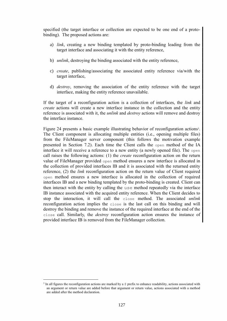
127
specified (the target interface or collection are expected to be one end of a proto-
binding). The proposed actions are:
a) link, creating a new binding templated by proto-binding leading from the
target interface and associating it with the entity reference,
b) unlink, destroying the binding associated with the entity reference,
c) create, publishing/associating the associated entity reference via/with the
target interface,
d) destroy, removing the association of the entity reference with the target
interface, making the entity reference unavailable.
If the target of a reconfiguration action is a collection of interfaces, the link and
create actions will create a new interface instance in the collection and the entity
reference is associated with it, the unlink and destroy actions will remove and destroy
the interface instance.
Figure 24 presents a basic example illustrating behavior of reconfiguration actions3.
The Client component is allocating multiple entities (i.e., opening multiple files)
from the FileManager server component (this follows the motivation example
presented in Section 7.2). Each time the Client calls the open method of the IA
interface it will receive a reference to a new entity (a newly opened file). The open
call raises the following actions: (1) the create reconfiguration action on the return
value of FileManager provided open method ensures a new interface is allocated in
the collection of provided interfaces IB and it is associated with the returned entity
reference, (2) the link reconfiguration action on the return value of Client required
open method ensures a new interface is allocated in the collection of required
interfaces IB and a new binding templated by the proto-binding is created. Client can
then interact with the entity by calling the use method repeatedly via the interface
IB instance associated with the acquired entity reference. When the Client decides to
stop the interaction, it will call the close method. The associated unlink
reconfiguration action implies the close is the last call on this binding and will
destroy the binding and remove the instance of the required interface at the end of the
close call. Similarly, the destroy reconfiguration action ensures the instance of
provided interface IB is removed from the FileManager collection.
3 In all figures the reconfiguration actions are marked by a @ prefix to enhance readability, actions associated with
an argument or return value are added before that argument or return value, actions associated with a method
are added after the method declaration.

128
Figure 24. Example – Client/FileManager
7.4.1 Entity References
All entity references representing entities have to originate from somewhere in the
component architecture. More precisely, the first component publishing the entity
reference in the architecture can be defined as an owner of the entity reference (and
the entity behind it). We aim to support two types of entity reference owners: (i) a
primitive component publishing an internal data structure or object, (ii) a
dynamically created component publishing references to its own interfaces -- these
are defined later in Section 7.4.4. The owner of an entity reference is known in the
architecture only at the exact level of nesting, where the owner resides. Everywhere
else in the architecture entity references fall into two groups at a certain level of
nesting:
1) Type A, no information about the entity reference is available to the
component system, thus it can be only passed to other components, but
cannot be used to establish any bindings,
2) Type B, the entity reference has been published via a reconfiguration action.
The interface used to publish the entity reference on such a component is then
defined as a local source; reconfiguration actions can be applied only to this
type of entity references.
If the owner component of an entity reference is known at a certain level of the
architecture the entity reference is supposed to be of type B and the local source is
defined to be the source interface of the owner. Entity references identifying the
same entity (originating from the same interface of the owner) can be of both types A
and B on different levels of nesting.
To simplify the description of architecture reconfiguration actions other criteria can
be used to further divide the entity references into two disjoint groups:
129
1) Entering references, i.e., entity references passed as input arguments of
methods in provided interfaces, or as output arguments and return value of
methods in required interfaces.
2) Leaving references, i.e., entity references returned as output arguments and
return value of methods in provided interfaces, or input arguments of methods
in required interfaces.
7.4.2 Basic Reconfiguration Actions
The goal of this section is to elaborate the four basic reconfiguration actions that
were introduced in the overview at the beginning of Section 7.4. To the general
properties of reconfiguration actions, the following should be added:
1) A reconfiguration action is always defined on an interface instance of a
particular component and not generally on an interface type. As illustrated by
examples in this section, a method of one interface type can have, and
typically will have, associated different reconfiguration actions in different
contexts (e.g., the difference in provided and required interface).
2) The actions can be associated not only with a direct argument of a method,
but also with a method itself. Then by stating an action is associated with a
method we mean the action is in fact associated with the “this” hidden
argument of the method, i.e., it influences the reference on which the methods
call occurs.
3) A reconfiguration action can be associated only with entity references that are
of type B in the given context, i.e., the local source (interface) of the entity
reference is known.
The section concludes with complete definitions of each of the four basic
reconfiguration actions:
a) link, creates new binding templated by a proto-binding leading from the target
interface of the action. The other end of the proto-binding has to be a local
source of the entity reference the link action is associated with. On composite
components, the link also makes the target interface the local source of the
entity reference for the immediate lower level of nesting inside the
component with the target interface, i.e., the target component. Thus, the link
action defines the entity reference to be of type B at the lower level of
nesting. If the link action is omitted in the method specification, the entity
reference would be only of type A in the lower level of nesting context, i.e.,
subcomponents would be only able to pass or store the reference, but would
not be able to create a binding using the link action and call methods on the
reference.
On entering references, the action executes when the entity reference is
received – i.e., during invocation of an incoming call with input references
and during return of an outgoing call with output references. Using the action
on leaving references makes sense only in the context of a caller – then the
action executes during the call invocation.
130
b) unlink, undefines the target interface as the local source of the associated
entity reference at the immediate lower level of nesting and removes the
binding from the target interface to the local source at the level of nesting the
target component resides.
On entering references, the action executes always at the end of a method call
– i.e., when returning from an incoming call or when an outgoing call returns.
The unlink action can be used in both caller and callee contexts on leaving
references and also executes when a method call ends. The unlink action can
be associated with method arguments, as well as methods themselves.
c) create, on primitive components, it prepares the associated entity reference
(directly representing the internal state of the component, e.g., an object
instance) to be sharable, plus defines the component as the owner of the
entity reference, implying the create action target interface becomes the local
source of the entity reference.
On composite components (that, if not dynamically created as defined in
Section 7.4.4, cannot own entity references), the create action creates a new
internal binding templated by proto-binding leading to local source of the
entity reference at the immediate lower level of nesting inside the target
component. Again, the target interface becomes the local source of the entity
reference at the level of nesting containing the target component.
Similarly, as the link action makes the associated entity reference type B in
the inner context of the target component, the create actions makes the entity
reference type B in the outer context of the target component, i.e., at the same
level of nesting the target component resides (component environment).
Without the create action the entity reference would be only of type A to the
component environment.
The action is valid only on leaving reference} and always executes at the time
the entity reference is being passed – i.e., in caller context, during the method
invocation and in callee context, during the method return.
d) destroy, undefines the target interface as the local source of the associated
entity reference and, on composite components, also removes the internal
binding leading to the internal local source of the entity reference.
The action, being an inverse to the create action, can be used only on entering
references and again executes as the reference is being received – i.e., in
caller context, during method return and, in callee context, during method
invocation. The destroy action can be associated with method arguments, as
well as methods themselves.
7.4.3 Examples of Basic Reconfiguration Actions
In this section, we present other typical examples of using different reconfiguration
actions at the level of design architecture to form a description of the allowed

131
architectural evolution. The first example was presented in the introduction of
Section 7.4.
The second example (Figure 25) shows the importance of timing of architectural
change denoted by each reconfiguration action. The example represents a common
pattern of passing a callback reference -- the entity reference is passed in opposite
direction than in the first example. The binding to Client's entity (the callback) will
be established at the beginning of the performWith method call, allowing the
Worker to call back to Client during the call. At the end of the originating call the
binding is destroyed again – so that the Worker is not allowed to call the Client out of
the specific window provided by Client via the performWith call.
Figure 25. Example – Callback
The third example (Figure 26) shows the behavior of reconfiguration actions in a
context of nested components (if we no longer look at the Client from Figure 24 as
on a black box) and also illustrates component ability to just pass the received entity
references without a need to create a binding to the originating component. An
important note is that making the Client a composite component does not change the
reconfiguration actions on its frame, but its behavior is refined by the reconfiguration
actions associated with its subcomponents. The Security component opens the
entities on Server, but does not use them directly (only passes them to the Worker
component). This way, no reconfiguration actions are needed on any of its methods.
On the other hand, the Worker component needs a binding to interact with Server
entities, so the link action is required on the method argument where it receives the
entity reference – i.e., on the performWith method. Similarly to the first example of
the whole Client frame, the unlink action is required on the close method. Worth
noting is also the inherent mechanism of partial building of bindings from Worker
component back to the Server component – the first half (between Client and Server)
will be created at the end of the open call, but the second half (between Worker and
Client frame) won't be created until the beginning of the performWith call. Should
the Server component be also composite, the same partial building would occur
inside it as the open method call returns up through Server hierarchy.
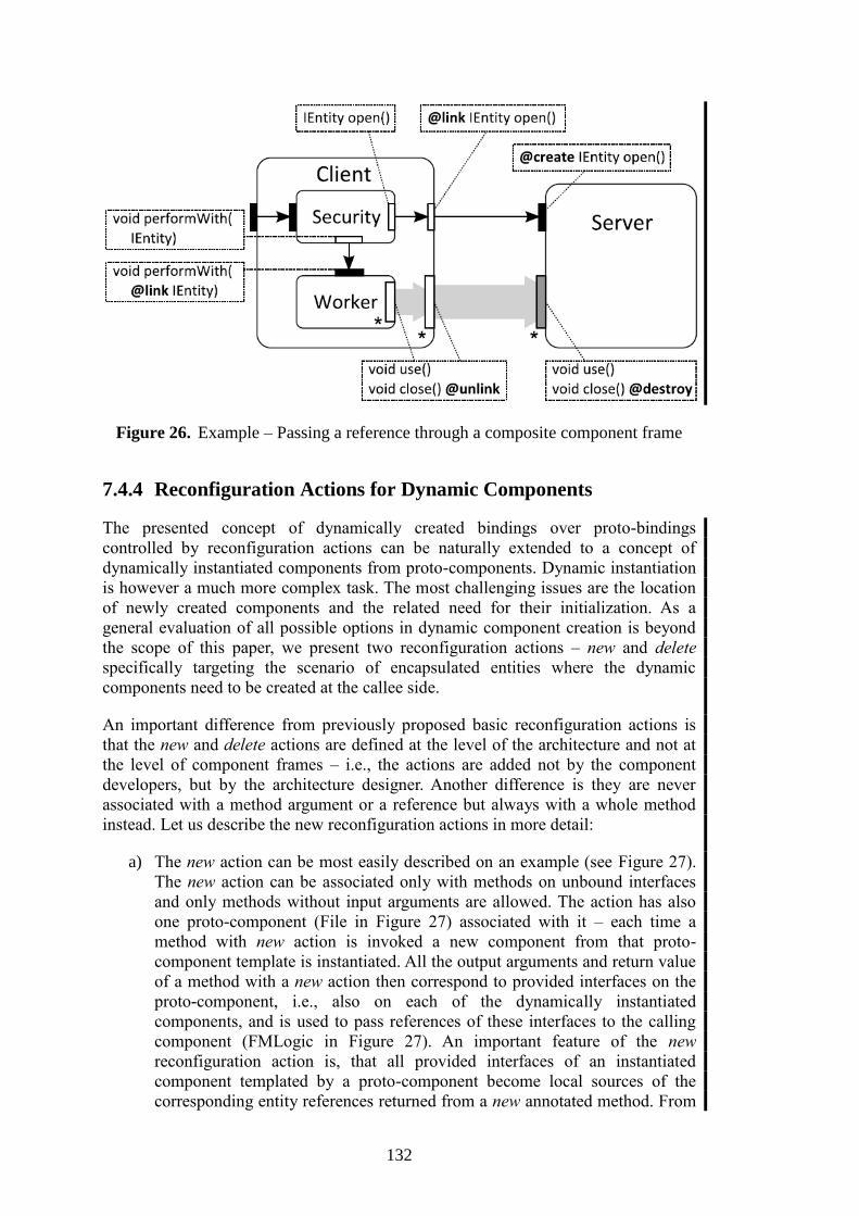
132
Figure 26. Example – Passing a reference through a composite component frame
7.4.4 Reconfiguration Actions for Dynamic Components
The presented concept of dynamically created bindings over proto-bindings
controlled by reconfiguration actions can be naturally extended to a concept of
dynamically instantiated components from proto-components. Dynamic instantiation
is however a much more complex task. The most challenging issues are the location
of newly created components and the related need for their initialization. As a
general evaluation of all possible options in dynamic component creation is beyond
the scope of this paper, we present two reconfiguration actions – new and delete
specifically targeting the scenario of encapsulated entities where the dynamic
components need to be created at the callee side.
An important difference from previously proposed basic reconfiguration actions is
that the new and delete actions are defined at the level of the architecture and not at
the level of component frames – i.e., the actions are added not by the component
developers, but by the architecture designer. Another difference is they are never
associated with a method argument or a reference but always with a whole method
instead. Let us describe the new reconfiguration actions in more detail:
a) The new action can be most easily described on an example (see Figure 27).
The new action can be associated only with methods on unbound interfaces
and only methods without input arguments are allowed. The action has also
one proto-component (File in Figure 27) associated with it – each time a
method with new action is invoked a new component from that proto-
component template is instantiated. All the output arguments and return value
of a method with a new action then correspond to provided interfaces on the
proto-component, i.e., also on each of the dynamically instantiated
components, and is used to pass references of these interfaces to the calling
component (FMLogic in Figure 27). An important feature of the new
reconfiguration action is, that all provided interfaces of an instantiated
component templated by a proto-component become local sources of the
corresponding entity references returned from a new annotated method. From
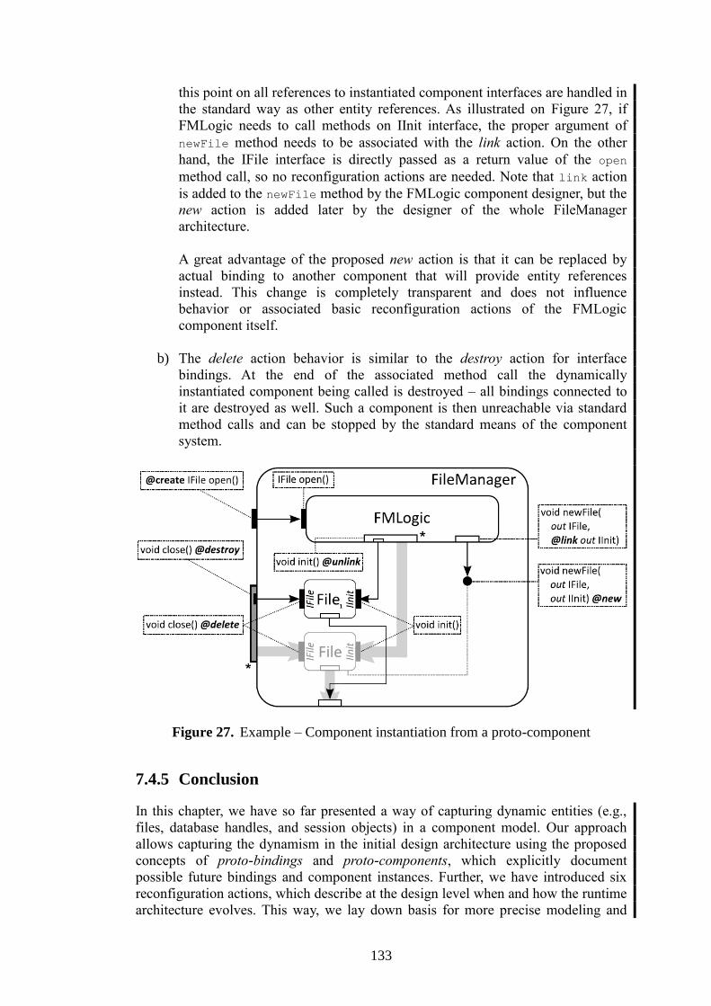
133
this point on all references to instantiated component interfaces are handled in
the standard way as other entity references. As illustrated on Figure 27, if
FMLogic needs to call methods on IInit interface, the proper argument of
newFile method needs to be associated with the link action. On the other
hand, the IFile interface is directly passed as a return value of the open
method call, so no reconfiguration actions are needed. Note that link action
is added to the newFile method by the FMLogic component designer, but the
new action is added later by the designer of the whole FileManager
architecture.
A great advantage of the proposed new action is that it can be replaced by
actual binding to another component that will provide entity references
instead. This change is completely transparent and does not influence
behavior or associated basic reconfiguration actions of the FMLogic
component itself.
b) The delete action behavior is similar to the destroy action for interface
bindings. At the end of the associated method call the dynamically
instantiated component being called is destroyed – all bindings connected to
it are destroyed as well. Such a component is then unreachable via standard
method calls and can be stopped by the standard means of the component
system.
Figure 27. Example – Component instantiation from a proto-component
7.4.5 Conclusion
In this chapter, we have so far presented a way of capturing dynamic entities (e.g.,
files, database handles, and session objects) in a component model. Our approach
allows capturing the dynamism in the initial design architecture using the proposed
concepts of proto-bindings and proto-components, which explicitly document
possible future bindings and component instances. Further, we have introduced six
reconfiguration actions, which describe at the design level when and how the runtime
architecture evolves. This way, we lay down basis for more precise modeling and

134
code generation, as we have also pointed out in this paper. The proposed approach
works seamlessly both for flat and hierarchical component models. As for the future
work, we plan to focus on adjusting our formalism for behavior modeling to reflect
the proposed approach and also to focus more on a general way of component
instantiation and initialization.
7.5 Evaluation – Enhancing the CRE Case-study Model
The goal of this section is to verify the concepts presented in this chapter so far and
to show there are viable to model complex component architectures. Target
application selected is the demo application from the CRE case-study – in Section
5.3.1 we have presented the problems in modeling the original Token component
using the existing CBSE concepts. In the original architecture (which was up to now
inherently static) the Token component had to be represented as a single instance,
whereas in the real application it would stand for a varying number of Token
instances that would be created and destroyed dynamically at runtime according to
needs of clients connecting to the application. Furthermore, there were multiple
points in the architecture where the Token component instances can originate from
(FlyTicketDatabase component – either directly or resent via FrequentFlyerDatabase
component; or AccountDatabase component) and each of the creators could provide
a slightly modified version of Token component (with or without CustomToken
inner component).
As the new architecture is intended to verify the dynamic entities concepts, the whole
CRE case-study application has not been modeled – the irrelevant parts have been
omitted from the architecture to keep it easily readable (so the figure illustrating it
can fit to a single page) – these are namely: Firewall and DhcpServer component, all
the services outside of the actual component architecture (remote services, clients,
web application, etc.), and the CardCenter and AccountDatabase components (while
these components play a similar role in the Token instantiation as the
FlyTicketDatabase and FrequentFlyerDatabase components do [that are modeled],
our solution with dynamic entities is designed in a consistent and generic way, and
the interconnection of AccountDatabase to the Arbitrator component would be the
same as for the FlyTicketDatabase and Arbitrator components, thus to further
simplify the architecture the AccountDatabase has been omitted as well). Also the
internal components of the FlyTicketDatabase component have been reduced to a
single representative, the AfDbConnection component. The architecture of the other
Connection components and their composition into the FlyTicketDatabase
component would be exactly the same as is the design of the AfDbConnection
component.
Furthermore the component interfaces were simplified to contain only methods
relevant to dynamic architectural changes for similar reasons. The following table
summarizes the symbols used in figures illustrating the architecture (note that
interface instances without annotation contain only methods that have no
reconfiguration actions associated with them or with any of their arguments or return
value):
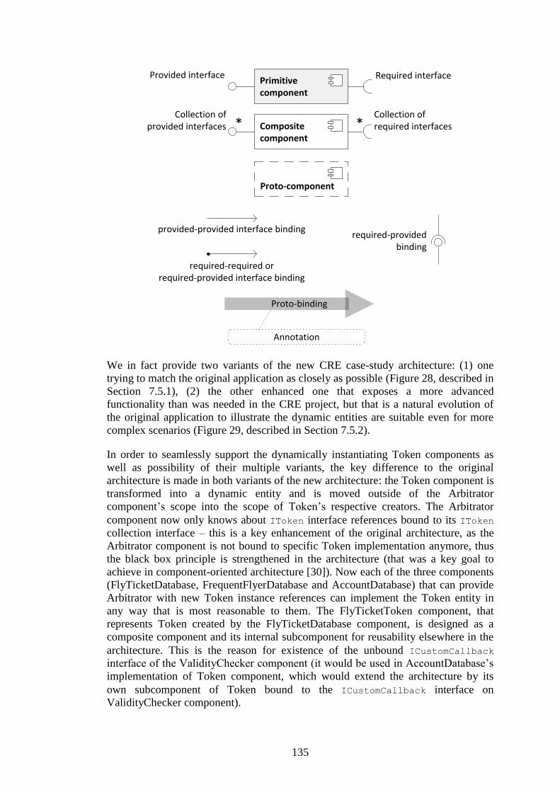
135
We in fact provide two variants of the new CRE case-study architecture: (1) one
trying to match the original application as closely as possible (Figure 28, described in
Section 7.5.1), (2) the other enhanced one that exposes a more advanced
functionality than was needed in the CRE project, but that is a natural evolution of
the original application to illustrate the dynamic entities are suitable even for more
complex scenarios (Figure 29, described in Section 7.5.2).
In order to seamlessly support the dynamically instantiating Token components as
well as possibility of their multiple variants, the key difference to the original
architecture is made in both variants of the new architecture: the Token component is
transformed into a dynamic entity and is moved outside of the Arbitrator
component’s scope into the scope of Token’s respective creators. The Arbitrator
component now only knows about IToken interface references bound to its IToken
collection interface – this is a key enhancement of the original architecture, as the
Arbitrator component is not bound to specific Token implementation anymore, thus
the black box principle is strengthened in the architecture (that was a key goal to
achieve in component-oriented architecture [30]). Now each of the three components
(FlyTicketDatabase, FrequentFlyerDatabase and AccountDatabase) that can provide
Arbitrator with new Token instance references can implement the Token entity in
any way that is most reasonable to them. The FlyTicketToken component, that
represents Token created by the FlyTicketDatabase component, is designed as a
composite component and its internal subcomponent for reusability elsewhere in the
architecture. This is the reason for existence of the unbound ICustomCallback
interface of the ValidityChecker component (it would be used in AccountDatabase’s
implementation of Token component, which would extend the architecture by its
own subcomponent of Token bound to the ICustomCallback interface on
ValidityChecker component).
Primitive component
Composite component
Proto-component
Provided interface Required interface
Collection ofprovided interfaces
Collection ofrequired interfaces
provided-provided interface binding
required-required orrequired-provided interface binding
Proto-binding
Annotation
required-providedbinding
* *

136
7.5.1 Basic Architecture with Entities
The basic architecture is depicted on Figure 28 – both Arbitrator and
FrequentFlyerDatabase are primitive components in the architecture, only the
FlyTicketDatabase is a composite component. It is designed to be generic, thus the
Token component is not instantiated directly by the FlyTicketDatabase, but the task
is forwarded to the AfDbConnection component. The process of creating a new
Token component based on fly ticket ID submitted by application’s client is initiated
by the Arbitrator component, that receives the client request. The whole process can
be divided into several steps:
1. The Arbitrator component creates callback object specific for the new
Token component to be created, and exposes it as an entity via its
ITokenCallback interface. The actual exposure is done by Arbitrator’s call
to IFlyTicketDb.CreateToken method on the FlyTicketDatabase
component due to the create reconfiguration action annotation on the
ITokenCallback argument. Note, that the Arbitator will hold one callback
object for each Token component it creates in this way and uses them as a
unique identifier to track request from Token components.
2. The FlyTicketClassifier (after choosing a correct component representing
the specific airline – AfDbConnection for Air France in the example) will
pass the request to the AfDbConnection component. The link annotation on
the ITokenCallback argument of CreateToken method will expose the
Arbitrator’s callback entity (object) reference to the internals of the
AfDbConnection component.
3. The requested token will be represented by a new instance of
FlyTicketToken component instantiated from the proto-component by
AfDbConnectionCore calling the NewToken method (annotations on both
ends of NewToken method ensure correct composition of the
FlyTicketToken component to its neighborhood). Before returning the
IToken (FlyTicketToken instance reference) reference back to components
at higher levels of nesting, the AfDbConnectionCore component will
initialize the FlyTicketToken via its ITokenInit configuration interface and
yield further communication with the token due to the destroy
reconfiguration action annotation on the SetTimeout method.
4. As the CreateToken method calls are finished at each level of nesting, the
FlyTicketToken instance reference (typed to IToken interface) will be
returned and, due to correct reconfiguration annotations on the
CreateToken return values, new binding is gradually build from the
FlyTicketToken component instance through the composite component
frames up to the Arbitrator’s IToken collection interface.
Note the FlyTicketClassifier component does not have any proto-binding linked to it,
as is does not need to communicate with the entity (component instance) behind
IToken interface returned from AfDbConnection.CreateToken call nor with the
Arbitrator’s callback entity referenced by ITokenCallback argument of its
CreateToken method. The FlyTicketClassifier simply passes the ITokenCallback

137
reference down to the lower levels of the architecture and the IToken reference up to
the higher levels as well. Everything else is managed by the annotations with right
reconfiguration actions.
Figure 28. Basic architecture of the CRE case-study with entities.
The FrequentFlyerDatabase component in Figure 28 is implemented in a similar way
the FlyTicketClassifier component is. As it only translates a frequent flyer ID into a
valid fly ticket ID, which it in turn uses to query the FlyTicketDatabase for a new
Token, it does not have to create its own Token instance. Thus it passes
Timer
ITimerCallback
ITimer
ValidityChecker
ITokenITokenCallback
ICustomCallback
FlyTicketToken
ITokenITokenCallback
ITokenInit ITokenInit
AfDbConnectionCore
IFlyTicketDb
AfDbConnection
IFlyTicketDbITokenCallback
IToken
SetTimeout(DateTime) @unlink
SetTimeout(DateTime) @destroy
InvalidateAndSave() @delete
@create IToken CreateToken( @link ITokenCallback)
void NewToken( @link ITokenCallback out IToken out ITokenInit) @new
void NewToken( ITokenCallback out IToken @link out ITokenInit)
Invalidated() @unlink
Invalidated() @unlink InvalidateAndSave() @destroy
FlyTicketClassifier
IFlyTicketDb
IFlyTicketDb
FlyTicketDatabase
ITokenCallback IToken
Arbitrator
IFlyTicketDb
IToken
ITokenCallback
IFreqFlyerAuth
FrequentFlyerDatabase
IFlyTicketDb
@link IToken CreateToken( @create ITokenCallback)
InvalidateAndSave() @unlink
Invalidated() @destroy
@link IToken CreateToken( @create ITokenCallback)
* *
* *
**
*
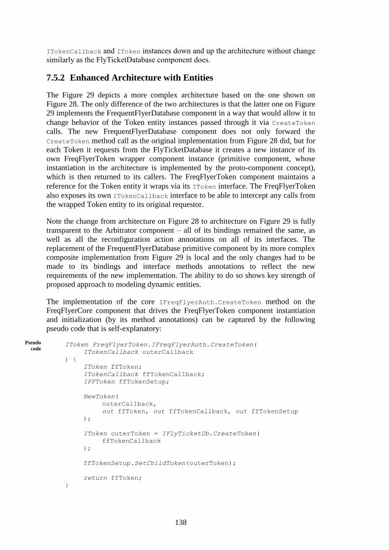
138
ITokenCallback and IToken instances down and up the architecture without change
similarly as the FlyTicketDatabase component does.
7.5.2 Enhanced Architecture with Entities
The Figure 29 depicts a more complex architecture based on the one shown on
Figure 28. The only difference of the two architectures is that the latter one on Figure
29 implements the FrequentFlyerDatabase component in a way that would allow it to
change behavior of the Token entity instances passed through it via CreateToken
calls. The new FrequentFlyerDatabase component does not only forward the
CreateToken method call as the original implementation from Figure 28 did, but for
each Token it requests from the FlyTicketDatabase it creates a new instance of its
own FreqFlyerToken wrapper component instance (primitive component, whose
instantiation in the architecture is implemented by the proto-component concept),
which is then returned to its callers. The FreqFlyerToken component maintains a
reference for the Token entity it wraps via its IToken interface. The FreqFlyerToken
also exposes its own ITokenCallback interface to be able to intercept any calls from
the wrapped Token entity to its original requestor.
Note the change from architecture on Figure 28 to architecture on Figure 29 is fully
transparent to the Arbitrator component – all of its bindings remained the same, as
well as all the reconfiguration action annotations on all of its interfaces. The
replacement of the FrequentFlyerDatabase primitive component by its more complex
composite implementation from Figure 29 is local and the only changes had to be
made to its bindings and interface methods annotations to reflect the new
requirements of the new implementation. The ability to do so shows key strength of
proposed approach to modeling dynamic entities.
The implementation of the core IFreqFlyerAuth.CreateToken method on the
FreqFlyerCore component that drives the FreqFlyerToken component instantiation
and initialization (by its method annotations) can be captured by the following
pseudo code that is self-explanatory:
IToken FreqFlyerToken.IFreqFlyerAuth.CreateToken(
ITokenCallback outerCallback
) {
IToken ffToken;
ITokenCallback ffTokenCallback;
IFFToken ffTokenSetup;
NewToken(
outerCallback,
out ffToken, out ffTokenCallback, out ffTokenSetup
);
IToken outerToken = IFlyTicketDb.CreateToken(
ffTokenCallback
);
ffTokenSetup.SetChildToken(outerToken);
return ffToken;
}
Pseudo
code
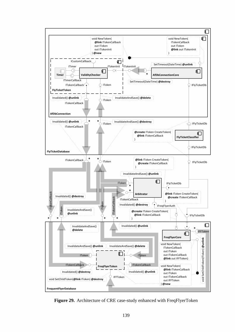
139
Figure 29. Architecture of CRE case-study enhanced with FreqFlyerToken
Timer
ITimerCallback
ITimer
ValidityChecker
ITokenITokenCallback
ICustomCallback
FlyTicketToken
ITokenITokenCallback
ITokenInit ITokenInit
AfDbConnectionCore
IFlyTicketDb
AfDbConnection
IFlyTicketDbITokenCallback
IToken
SetTimeout(DateTime) @unlink
SetTimeout(DateTime) @destroy
InvalidateAndSave() @delete
@create IToken CreateToken( @link ITokenCallback)
void NewToken( @link ITokenCallback out IToken out ITokenInit) @new
void NewToken( ITokenCallback out IToken @link out ITokenInit)
Invalidated() @unlink
Invalidated() @unlink InvalidateAndSave() @destroy
FlyTicketClassifier
IFlyTicketDb
IFlyTicketDb
FlyTicketDatabase
ITokenCallback IToken
Arbitrator
IFlyTicketDbIToken
ITokenCallback
IFreqFlyerAuth
IFlyTicketDb
@link IToken CreateToken( @create ITokenCallback)
InvalidateAndSave() @unlink
Invalidated() @destroy
@link IToken CreateToken( @create ITokenCallback)
FreqFlyerTokenITokenCallback
IToken IToken
ITokenCallback
@create IToken CreateToken( @link ITokenCallback)
FreqFlyerCore
FrequentFlyerDatabase
Invalidated() @unlink
InvalidateAndSave() @deleteInvalidateAndSave() @unlink
ITo
ken
Cal
lbac
k
ITo
ken
ITo
ken
Cal
lbac
k
ITo
ken
Invalidated() @unlinkInvalidateAndSave() @delete
InvalidateAndSave() @unlink
Invalidated() @destroy
Invalidated() @destroy
void NewToken( @link ITokenCallback out IToken out ITokenCallback out IFFToken) @new
void SetChildToken(@link IToken) @destroy
void NewToken( ITokenCallback out IToken out ITokenCallback @link out IFFToken)
IFFToken
IFFToken
void
Set
Ch
ildTo
ken
(ITo
ken
) @
un
link
* *
* *
**
* * * *
*
*

140
7.5.3 Summary
As shown is Section 7.5.1 and Section 7.5.2 above, our approach to capturing
dynamic architectural changes by concept of dynamic entities implemented via
concepts of proto-binding, proto-components and reconfiguration actions is viable
and can be successfully used to describe complex architectures in a consistent way. It
is a key success as to our best knowledge no previously known and implemented
approach is able to model the presented dynamic architecture of the CRE case-study
in a way to capture all information necessary for the reconfigurations both in the
design and runtime architectures (i.e. usable both for static and runtime application
analysis tools, as well as the component model runtime itself).
A final note on the subject is that the concept of dynamic entities and the four basic
reconfiguration actions were already successfully implemented in a real component
system. In [14] the SOFA 2 runtime has been extended with support for dynamic
entities as prove of concept implementation. It shows the proposed approach is viable
not only for modeling of complex applications, but also for their implementation in
hierarchical component models.
141
Chapter 8 Modeling Environment using DeSpec
In recent years, efforts to verify correctness of Windows kernel drivers [124] have
emerged as it is crucial for stability of the whole operating system. Microsoft itself
has developed several tools for driver verification including the latest Static Driver
Verifier model checker. The key to successful application of the model checking
approach in this area is a reasonable choice of the environment model. However, the
environment models used in current tools are too (1) non-deterministic, degrading
preciseness of the model checker reports, and (2) oversimplified, losing the ability to
check more specific kinds of properties of drivers. On the other hand, neither a
formal or readable specification usable for documentation purposes is provided by
these models. This paper targets these issues by introducing a new language for
formal specification and modeling of kernel drivers and their environment.
Please note that due to space limitations the paper presents only a small excerpt of
the language features. The full language specification, detailed elaboration of its
features and also a large sample specification of the Windows environment can be
found in [115].
8.1 Model Checking
Model checking technique is a formal verification method based on thorough
examination of a program model state space. The model reflects behavior of the
program related to the property being verified. It should ideally retain any part of the
software that might influence the property so that the verification is sound and
complete. On the other hand, the model should be as simple as possible since the
model checker has to explore all its possible states. The time and space requirements
for the verification are growing exponentially with respect to the number of
operations, threads and variables used in the model (the state explosion problem
[116]).
Usually, the goal is not to model check the system as a whole. Instead, the system is
split into two pieces – a particular component of interest (a module, also an open
system [172]) and the rest of the system (the module's environment). The
environment is considered correct and its provided and required interfaces are
defined by a specification. The verification tool is expected to extract a partial model
from the module's source code and complete it by including the environment's
behavior model according to the specification. The resulting model passed to the
model checker, captures the module's interaction with the environment relevant to a
set of properties being verified.
The process of model extraction from the program's source code is a difficult task as
the source code language itself can induce major problems. A C language extractor
needs to understand constructs like pointers, arrays, unions, reinterpreting type casts,
etc. Fortunately, even though some of these constructs in general allow the extractor
to build neither sound nor complete model of the program, results of the software
DeSpec
142
verification are still valuable. All the issues of the model extraction from the C
source code have already been presented in paper [114].
This paper focuses on a formal description of the environment that combines the
requirements on the module and modeling of the functionality provided by the
environment. Temporal logics (e.g. Linear Temporal Logic (LTL) [104]) are often
used for the former. They define how properties of the system should change in time
using predicates quantified over time variable. However, specifying properties of a
real application by means of plain temporal logic comes with a significant drawback.
The specification is not easy to comprehend for the most of driver programmers and
if a formula gets more complex neither for temporal logic experts.
Plain logic unreadability drives efforts to develop a higher-level language like
Bandera Temporal Logic Patterns [60]. Properties expressed in this language are
translated into the temporal logic formulae consumed by many existing verification
tools. The patterns allow writing frequently used temporal logic formulae in very
simple plain English sentences, e.g. “P is absent between Q and R” is representing
the following formula:
Though incomplete the patterns are sufficient to specify widely used properties.
Moreover, additional patterns can be added to the repertoire if needed.
Note:
In our work, we use Zing modeling language [10][119] as a basis for specification of
the environment behavior and also as the output language of the model extractor.
Zing language and Zing model checker have been developed by Microsoft Research
group. The choice was made due to Zing's rich modeling functionality and the state
of its current development (the preview implementation is available and works quite
well). However, most ideas behind this work are not dependent on the target
modeling language and can be applied to any other modeling language that provides
at least classes, methods, exceptions, non-deterministic choices, and threads. Another
modeling language meeting these criteria should be the new version of Bandera
Intermediate Representation (BIR) – a modeling language of Bogor model checking
framework [154].
8.2 Verification of Windows Drivers’ Correctness
Windows kernel drivers are relatively small libraries usually written in the C
language. They run in a privileged mode that enables them to work directly with
hardware. This introduces a high risk of damaging other parts of the kernel if a driver
contains an error. Hence the correctness of drivers is crucial for security and stability
of an operating system and drivers are common subject of software verification.
A driver can be seen as a component put into the environment comprising of the
kernel and other drivers. Since drivers usually communicate with each other only via
kernel function calls the inclusion of the other drivers into the environment is an

143
acceptable simplification. The verifier deals with the open system verification as the
source code of the Windows kernel is usually not available. And even if it was, it
would be virtually impossible to extract and verify the kernel model due to its
inherent complexity. Besides, drivers shouldn't depend on the exact behavior of the
private parts of the kernel as they can change version to version. Only the public
documented functionality should be relied on.
So the model extractor should only work with the kernel specification. However,
such specification is not currently available in a form that would be feasible to drive
the model extractor -- the only source of official documentation is the Driver
Development Kit (DDK) [123] provided by Microsoft, where the rules the drivers
should comply with are described in plain English and some important details are
stated vaguely or even missing entirely. It is a goal of our work to provide a language
for writing the specification and to apply it on significant parts of the kernel API.
Several tools that verify driver correctness have already been developed by Microsoft
itself. These include the Driver Verifier [120] tool for run-time driver verification, the
PREfast [121] static analysis tool based on local analysis of driver functions and
finally the Static Driver Verifier (SDV) [122] (still in development) based on
techniques of static analysis of the whole driver and model checking.
The Static Driver Verifier (SDV) models the kernel environment in C language
enriched with special functions and macros that handle non-determinism necessary
for emulating various execution paths. The rules the drivers can be verified against
are written in Specification Language for Interface Checking (SLIC) [18]. Expressing
a rule in the SLIC language inheres in writing pieces of C pseudo-code and defining
how the environment model should be instrumented by them. The resulting
instrumented code is converted to an abstract Boolean program which is passed to
the model checker. The very first Boolean program extracted from the instrumented
code abstracts from all local variables and replaces all conditions by non-
deterministic choices. Error traces are then discovered by the model checker and
confronted with the original program via symbolic execution. If an error trace
describes the execution that is actually infeasible, the Boolean program is refined to
be more specific with respect to the variables influencing the trace. The refined
program is passed back to the model checker. This process of error search and model
specialization repeats until there are no infeasible error traces found or a timeout
elapses.
The environment model and the SLIC language allows safety properties to be
checked with respect to operations performed sequentially on a single device object
(an object representing a device in the driver). SLIC rules are limited to safety
properties so it is not possible to encode all the rules defined in the DDK. The rules
are specified separately from kernel environment which makes them less
maintainable. Inability to model multi-threaded environment and simultaneous work
on more device objects also prevents from verification of some race conditions
commonly contained in faulty Windows drivers. In this work we introduce a solution
that does not have these shortcomings.
Contribution
The aim of this work is to make it possible to specify and model the kernel
environment in a formal yet comprehensible form, which could be used not only for
144
precise documentation of the kernel API but above all as an input for a model
extractor that produces verifiable concurrent models of the Windows drivers. For this
purpose, the paper introduces a new specification and modeling language called
Driver Environment Specification Language (abbreviated as DeSpec). As shown in
[115], the language is able to capture a significant subset of the rules imposed on
drivers by the DDK including those that are difficult or impossible to express in the
SLIC language and hence currently not verifiable by the SDV.
8.3 Windows Kernel Environment
The Windows kernel executive comprises of several components that manage
various system resources – the managers [162]. The managers provide services for
the other parts of the executive and for drivers. The I/O Manager, the Plug & Play
Manager, and the Power Manager are the ones that are most interesting for driver
verification as they do the majority of communication with drivers. Note, this work is
limited only to drivers following the Windows Driver Model (WDM) [138]. Such
drivers have to implement Plug & Play and power management features.
The I/O Manager loads and unloads drivers and issues I/O requests on them. The
drivers are directly controlled by the I/O Manager, which issues I/O requests in form
of I/O Request Packets (IRPs). If a driver can complete the request it fills in a place
in the packet reserved for output parameters and passes the packet back to the
manager. If it doesn't implement the required functionality it can pass the request to
an optional lower level driver – a hierarchy is being formed by such inter-driver
relationships. The other managers issue their requests and notifications to the drivers
through the I/O Manager. For example, the Plug & Play Manager keeps track of the
device state transitions (device removal, stopping, starting, etc.) and the Power
Manager monitors the power state of the machine (whether it is going to sleep,
awaking, etc.). Both managers notify the driver appropriately by sending it the
respective IRPs.
Each driver has to respond correctly to an arbitrary request and content of the packet.
It can return a result indicating an error, but it must never crash or damage other parts
of the kernel. The driver cannot make any assumptions about drivers above or below
it in the hierarchy. This requirement allows the verification tool to isolate the driver
and test it on arbitrary inputs and outputs from the I/O Manager and higher/lower
level drivers.
8.4 Driver Environment Specification Language
The Driver Environment Specification Language (DeSpec) is an object-oriented
specification and modeling language incorporating the majority of features of the
Zing modeling language [10] combined with design-by-contract elements inspired by
Spec# language [20], and Bandera Temporal Logic Patterns [60]. It is designed to
guide extraction of Zing models from source code of Windows kernel drivers.
DeSpec language allows modeling of I/O Manager's behavior to drivers, modeling of
kernel functions behavior and specifying constrains and rules that drivers should
obey when calling these functions. Models and abstractions can be defined in various
levels of detail, which, as one of the solutions fighting against the state space
145
explosion problem, enables the model extractor to infer the smallest available model
sufficient for the verification of a particular rule.
DeSpec language provides means for capturing basic elements of the interaction
between driver and its environment (i.e. global variables, functions and data
structures). It is designed as a bridge between constructs of the C language and their
models in the Zing language. In particular the models of pointers, function pointers,
unions and other constructs that are not directly expressible in the Zing language are
hidden behind the syntax of DeSpec language. This allows adjusting models for these
features without a need to rewrite the specifications. Apparently, some constructs
exploiting memory layout, such as reinterpreting casts or unions, cannot be modeled
in a feasible way. Therefore they are not directly expressible in the DeSpec language.
Fortunately, the driver as well as environment interface should be as platform
independent as possible and thus these constructs should be used rarely.
8.4.1 Structure of Specifications
The DeSpec language is similar to the C# language in its syntactical structure. Each
source file contains a list of declarations grouped to namespaces. Declarations
include classes, integer enumerations, integer ranges, method delegates and method
groups. A class declaration comprises of its members. Apart from fields and methods,
which are common for standard object-oriented languages, DeSpec classes can also
contain rules. A rule specifies constrains on fields and methods by means of temporal
logic patterns. This section briefly describes DeSpec namespaces, classes and rules.
Namespaces
A namespace defines a scope for abstractions of kernel functions and structures.
When the model extractor searches for an abstraction of a kernel function or a
structure used in the driver's source code it looks up a single namespace only. The
choice of the namespace depends on constrains to be verified. The default (global)
namespace describes a minimal model for kernel functions and structures. Other
namespaces usually refine the default model – making it more complex to enable
verification of a constraint not expressible by means of default model. Constraints
are embedded into the specification as method preconditions, postconditions, type
constrains, rules, etc. By choosing the constraint to verify, the containing namespace
is designated for being searched by the extractor. The ability to differentiate
specifications by level of details is important for reducing the size of the resulting
model.
Classes
Although Windows kernel is written in the C programming language its design is
object oriented. Usually, a structure representing an object within the kernel (e.g.
semaphore, mutex or device) is provided along with functions working with it. These
functions behave like methods of the structure (object) as they all take a pointer to
the structure as one of their parameters (the “this” reference). A notion of inheritance
is also present on several places. Inheritance is used for sharing data among
structures representing different yet related objects. The sharing technically inheres
in declaring common initial fields in the related structures.

146
These observations justify introduction of classes as main elements of the
specifications – the kernel structures provided to drivers are modeled in DeSpec as
classes. The functions bound to these structures are declared as class instance
methods. Functions not bound to any instance are mapped to static methods. The
formal parameter referring to the instance the method is working on is specified by
the instance keyword. The method (whether static or instance) abstracting a kernel
function has to have the same name as the kernel function and no other method in the
same namespace can have the same name (even though declared in another class).
This rule allows the model extractor to find a specification of a function whose call
has been observed in the source code. An example of a class specification follows:
Figure 30. DeSpec Example 1
In Example 1 (see Figure 30), the DEVICE_OBJECT class abstracts the structure of the
same name. Instances of the structure represent devices that drivers are working
with. Both IoAttachDevice and IoAttachDeviceToDeviceStack kernel functions attach
the device object to the top of the device objects chain. The immediate lower device
object, where the instance is attached to, is returned in the attachedTo output
DeSpec

147
argument and in the return value, respectively. The IoDetachDevice simply detaches
the immediate higher level device from this device object instance4.
The signature of a method abstracting a kernel function defines how parameters of
the function are treated within the specification. The placeholder token (a single
underscore) is used for arguments that are not important for the specification. The
models of IoAttach- functions do not care about the second parameter. When a
specification refers to the IoAttachDevice method, only one argument is stated in the
list of actual arguments. The instance argument is picked from the argument list out
before the method to denote the target instance using the dot notation. Arguments on
the positions of placeholders are also omitted in the actual argument list. Methods
declared in Example 1 (see Figure 30) are referred to as follows:
device.IoAttachDevice(out lower_device) device.IoAttachDeviceToDeviceStack() lower_device.IoDetachDevice() The out keyword specifies that the argument is an output argument and has to be
assigned within the method's body. The output argument is mapped to the C language
by an additional level of indirection. The C type of the argument is thus
DEVICE_OBJECT**. The ref keyword is also supported for marking arguments passed
in and out by reference. A possibly empty list of preconditions and postconditions
follows the signature. The syntax is similar to the one used in the Spec# language –
the conditions are introduced by requires and ensures keywords, respectively. The
condition is a Boolean expression with some limitations on the terms. The conditions
stated in Example 1 (see Figure 30) require the lowest level driver not to call the
IoAttach- functions. Pre- and postconditions are translated to assertions when the
Zing model of the method is generated.
The body defines a model of the method's behavior using Zing syntax enriched with
additional constructs that are translated to the Zing when the resulting model is
generated. In Example 1, extended forms of the Zing's choose operator are used.
Type NTSTATUS is an integer enumeration abstracting the kernel type of the same
name. The operator IsSuccessful determines whether a value is a successful value of
its type as recognized by the kernel.
The body can also be omitted at all if the modeled function does nothing that
influences the driver at the current level of abstraction and only its calls are
significant. If a kernel function returns some value to the caller (via a return value or
output parameters), throws an exception or has some side-effect the specification
method should have a body that models these operations.
Since a DeSpec class is usually an abstraction of a public kernel structure, it may
contain fields corresponding to the fields of the structure. Additional fields that do
not correspond to real fields might be necessary for storing auxiliary data used only
for the sole purpose of modeling. Such fields are marked by the synthetic keyword.
Similarly, synthetic methods and also synthetic classes can be defined in the
specification. In general, DeSpec distinguishes synthetic language elements from
4 Note the reverse roles of the device objects -- the higher level device object is attaching but the lower level
device object is detaching.
DeSpec
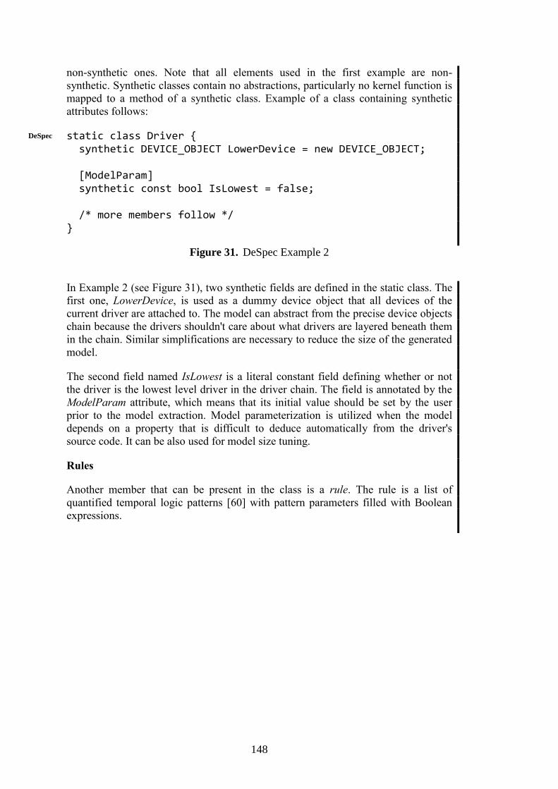
148
non-synthetic ones. Note that all elements used in the first example are non-
synthetic. Synthetic classes contain no abstractions, particularly no kernel function is
mapped to a method of a synthetic class. Example of a class containing synthetic
attributes follows:
static class Driver { synthetic DEVICE_OBJECT LowerDevice = new DEVICE_OBJECT; [ModelParam] synthetic const bool IsLowest = false; /* more members follow */ }
Figure 31. DeSpec Example 2
In Example 2 (see Figure 31), two synthetic fields are defined in the static class. The
first one, LowerDevice, is used as a dummy device object that all devices of the
current driver are attached to. The model can abstract from the precise device objects
chain because the drivers shouldn't care about what drivers are layered beneath them
in the chain. Similar simplifications are necessary to reduce the size of the generated
model.
The second field named IsLowest is a literal constant field defining whether or not
the driver is the lowest level driver in the driver chain. The field is annotated by the
ModelParam attribute, which means that its initial value should be set by the user
prior to the model extraction. Model parameterization is utilized when the model
depends on a property that is difficult to deduce automatically from the driver's
source code. It can be also used for model size tuning.
Rules
Another member that can be present in the class is a rule. The rule is a list of
quantified temporal logic patterns [60] with pattern parameters filled with Boolean
expressions.
DeSpec

149
class DEVICE_OBJECT { /* method declarations from Example 1 omitted */ static rule forall(DEVICE_OBJECT device) { _.IoAttachDevice(out device)::succeeded || (device === _.IoAttachDeviceToDeviceStack()) && device!=null } corresponds to { device.IoDetachDevice() } globally; }
Figure 32. DeSpec Example 3
The rule in Example 3 (see Figure 32) is a single pattern, however, in general, a rule
is a list of quantified temporal logic patterns separated by commas and ending by a
semicolon. The rule presented has the following meaning: “Each successfully
attached device is eventually detached and each device that is detached has
previously been successfully attached.” Rest of the section explains the patterns in
more detail. Each temporal logic pattern is formed by pattern keywords and pattern
expressions. The pattern used in Example 3 (see Figure 32) can be generalized to {P}
corresponds to {Q} globally, where {P} and {Q} are Boolean expressions. Each
pattern can be split into two parts: the property and the scope. In this case, the
property is {P} corresponds to {Q} and the scope is globally. A list of available
pattern properties follows:
Properties (i) to (vi) are defined in [60]. Properties (v) and (vi) are equivalent and it
depends on the situation which one is more appropriate to use. The property (vii) is
equivalent to a conjunction of properties (v) and (iv), i.e. to {Q} leads to {R} ˄ {Q}
precedes {R}. It has been introduced to the language since the combination is
frequently used in the kernel environment and it would be inconvenient to write the
two patterns separately. The available scopes are:
DeSpec

150
The meaning of each property and scope is obvious. Detailed definitions can be
found in [60] along with the equivalent LTL formulae. The LTL formula for Q-
corresponds-to-R pattern with the global scope is:
Temporal patterns can be quantified over value types or reference types. Patterns of
instance rules are implicitly quantified by a variable of the declaring type. Instance
rules can refer to that variable by using this keyword. This keyword can be omitted
when referring to the instance members of the type. Unlike Bandera specification
language [52], DeSpec allows quantifying over value types (i.e. integers, Boolean,
enumerations). Zing symbolic value types can be used for the implementation. The
reference type quantification may be implemented in the same way as in Bandera,
however more scalable implementation would be possible using Zing symbolic
reference types, which should be available in the next version of the Zing.
Figure 33. Source code event operators for methods. M stands for non-synthetic
methods, args stands for a list of arguments (possibly empty), and expr denotes an
expression.
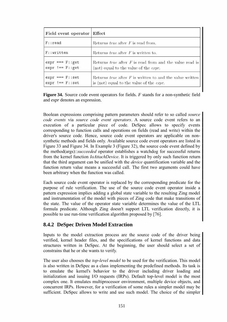
151
Figure 34. Source code event operators for fields. F stands for a non-synthetic field
and expr denotes an expression.
Boolean expressions comprising pattern parameters should refer to so called source
code events via source code event operators. A source code event refers to an
execution of a particular piece of code. DeSpec allows to specify events
corresponding to function calls and operations on fields (read and write) within the
driver's source code. Hence, source code event operators are applicable on non-
synthetic methods and fields only. Available source code event operators are listed in
Figure 33 and Figure 34. In Example 3 (Figure 32), the source code event defined by
the method(args)::succeeded operator establishes a watchdog for successful returns
from the kernel function IoAttachDevice. It is triggered by only such function return
that the third argument can be unified with the device quantification variable and the
function return value means a successful call. The first two arguments could have
been arbitrary when the function was called.
Each source code event operator is replaced by the corresponding predicate for the
purpose of rule verification. The use of the source code event operator inside a
pattern expression implies adding a global state variable to the resulting Zing model
and instrumentation of the model with pieces of Zing code that make transitions of
the state. The value of the operator state variable determines the value of the LTL
formula predicate. Although Zing doesn't support LTL verification directly, it is
possible to use run-time verification algorithm proposed by [76].
8.4.2 DeSpec Driven Model Extraction
Inputs to the model extraction process are the source code of the driver being
verified, kernel header files, and the specifications of kernel functions and data
structures written in DeSpec. At the beginning, the user should select a set of
constrains that he or she wants to verify.
The user also chooses the top-level model to be used for the verification. This model
is also written in DeSpec as a class implementing the predefined methods. Its task is
to emulate the kernel's behavior to the driver including driver loading and
initialization and issuing I/O requests (IRPs). Default top-level model is the most
complex one. It emulates multiprocessor environment, multiple device objects, and
concurrent IRPs. However, for a verification of some rules a simpler model may be
sufficient. DeSpec allows to write and use such model. The choice of the simpler
152
model may radically reduce the size of state space and make the verification faster
and sometimes even allow the verification to be completed in realistic time.
However, some errors may remain undiscovered.
Once the top-level model is chosen, the model extractor generates Zing model of the
driver (using its C source code and kernel headers) and combines it with the
environment model. Since the resulting model is too large to be verified, the slicing
[101][61] should take place retaining only those parts transitively referred to by the
top-level model and the constrains being verified. As a final result, a Zing model of
the driver and the related kernel functions and structures are output.
8.5 Conclusion and Future Work
This paper introduces the DeSpec language – a new specification and modeling
language designed to enable writing modular, readable, and well-arranged
specifications of the Windows kernel driver environment as well as formally, yet still
comprehensibly, capture rules imposed on drivers by the kernel and documented in
plain English in DDK.
Expressiveness and suitability of the language are demonstrated on a part of the
kernel functionality in [115]. This work also shows that the available documentation
of the kernel environment [123] is not sufficient for its formal specification without a
deeper understanding of the Windows kernel.
As the DeSpec language is intended to be utilized by model checking tools, it
addresses the main issue of this verification method – the state explosion problem.
The abstractions may vary in the level of detail chosen according to the properties
being verified. Complexity of the model can be further tuned by the user specified
model parameters. By setting these parameters, the user can influence how complex
the extracted model will be and what may it neglect. The user may also select a
subset of tested driver functionality by choosing an appropriate top-level model.
The possibility of verifying LTL formulae with finite trace semantics using assertions
only (see [76]) arises a question whether the use of temporal rules brings something
new beyond the use of explicit assertions. Although many rules may be equivalently
verified manually, i.e. by adding assertions (or method contracts) on the right places
in the functions' model code, the use of rules has some advantages. Several
advantages are implied by the locality. If entire “business logic” of the rule is written
on a single place it is easier maintainable, more readable, and the verification of the
rule can be easier (un)selected for verification. Besides, when the rule is more
complex it wouldn't be easy to manually keep track of all operations in the code that
influences the verified property. On the other hand, some rules are too complicated to
write or comprehend that it is better to implement them manually by explicit
assertions.
The ideas proposed by this paper are currently being implemented. The
implementation comprises of the DeSpec language analyzer and a model extractor
consuming C source code and producing a Zing model driven by DeSpec
specifications.
153
Chapter 9
Related Work
As the initial Chapter 1 to Chapter 3 of the thesis analyze the related work quite
extensively as an inherent part of the text and parts of motivations of the presented
papers also position themselves relative to the related work, in this chapter we
present only a rather short summary of related work not covered elsewhere in the
thesis.
9.1 Error Traces
In [78], the authors address the counterexample complexity and interpretation
problem by proposing a method for finding ”positives” and ”negatives” as sets of
related correct traces and error traces. An interesting approach is chosen in [102],
where the authors analyze the complexity of error explanation via constructing the
”closest” correct trace to a specific error trace. In [177], the authors describe an
algorithm (”delta debugging”) for finding a minimal test case identifying an error in
a program. This idea could be used to modify an error trace in order to find a ”close
enough” correct one. An optimization of the checking process is described in [17]
where multiple error traces are generated in a single checking run.
Static Driver Verifier (SDV) [122] is a tool used to verify correct behavior of WDM
(Windows Driver Model) [125] drivers. The driver’s source code in C and the model
written in SLIC (a part of the SLAM project [19][118]) are combined into a
”boolean” program that is maximally simplified and selected rules are checked. If a
rule is violated, an error trace of the program is generated and mapped back to the
driver’s C source code. Because WDM drivers are very complex, to make checking
feasible, both the Windows kernel model and the rules used in the SDV have to be
simplified. Thus the error traces generated by SDV are relatively short and easy to
interpret. And, since they contain also the states corresponding to traversing through
the kernel model, such parts are optionally hidden in the checking output. This
solution might be also applicable to our plain error traces (Section 5.4.3): The events
generated inside a method call could be grouped into the ”background” (Section
5.4.2). However, because it is not easy to identify the beginning and the end of a
single method call in error trace (especially when the i.m{...} shortcuts are not used),
employing this idea in the behavior protocol checker is not a trivial task.
As to the classical model checker SPIN [87][24], in case of violating of checking
property specified in LTL, Spin allows traversing the trace to the error state while
watching the variable values, process communication graph, and highlighted source
code. Sometimes the error trace length makes this approach very hard to use and
identification of the actual problem may be quite challenging. Although the
approaches to ease the interpretation of an error trace in SPIN work well in most
cases, its modeling language Promela [24] is not a suitable specifying software
FACS
154
components. Since such specification in Promela typically yields a large state space
impossible to traverse in a reasonable time.
As for other tools, Java PathFinder (JPF) [133], Bogor [154][153], BLAST [28][26],
SMV [159], Moped [127], and MAGIC [110] cope with counterexamples and all
provide them as error traces. Specifically, JPF, Bogor, BLAST, Moped, and MAGIC
print the sequence of steps leading to an error state annotated by a corresponding line
of the source code, while the SMV tool provides an error trace consisting of the input
file lines written in the SMV specification language. Moped is a similar to SDV in
the sense that it first translates the input program (in Java) into the language of LTL
in which the counterexamples are generated. They are then translated back to the
input language. The MAGIC tool checks behavior of a C program against a
specification described via an LTS. Besides an error trace, it can also generate
control flow graphs and LTSs using the dot tool of GraphViz package [77] (also used
by the behavior protocol checker). In all cases, but especially in the case of JPF, the
error trace may get quite complex and not easy to interpret.
9.2 Entities
Since the proposed extension influences many aspects of component-based
development, the related work ranges from formal verification methods through
description of architecture dynamism in component models and its support at runtime
to data modeling. To our best knowledge, there is no approach in the domain of
component-based systems that would tackle the problem of modeling dynamic
entities in a comprehensive fashion. However, there are works that solve some of the
aspects, though, often with different motivation.
9.2.1 Component Models with Support for Data Modeling
Although, the concept of data and data-flow modeling is well known and accepted in
different domains of software engineering, contemporary component models often
neglect this part of application design and do not provide any constructs of explicit
representation. Nevertheless, there are attempts to fill the gap.
In [106], the authors provide a formalization of data passing and data circulation
through a component-based application. The approach considers data as a part of a
component. The data can be accessed from other components, updated, and
transferred among components. The basic idea is to distinguish between control and
data flow. Dedicated data connectors manage access to data through a global shared
data space where data are created and shared. Although, the work tries to formalize
the area of component-based systems which is not deeply explored, we see the main
disadvantage in the shared data space where all data has to be stored and which can
cause a substantial overhead at runtime. Comparing to our approach, we preserve the
place where data are created.
Scade [103], Pin [83], PECOS [75], ProCom [158] propose a data-flow modeling
based on connecting components with input and output pins which represent required
and provided data. Such concept is typical for embedded systems where data are
produced by various sensors, processed by control components, and then they serve
as inputs for actuators. Such concept differs from our proposal where data are owned
by a particular component and just a data reference circulates in the application.
Entity
EntityTR
155
Providing persistency in component-based applications can be seen as a data
modeling approach [50], however this concept operates with the granularity of
components. However, we claim that it is not enough to represent typical application
data.
9.2.2 Behavior Specification and Verification
The need for associating properties directly with dynamic entities like a file is not
new. In the context of general code analysis, it has already been applied using
BLAST [26], SLAM [16]. The BLAST and SLAM model checkers allow inspecting
state space of a program in C for assertion violations. Moreover, there is additional
specification language that allows associating an additional (shadow) state with a C
structure and specifying allowed sequences of function calls using the structure.
Thus, it is possible to associate such shadow state with, e.g., the FILE structure in the
C library and restrict the correct usage patterns to those starting with a call to open
and ending with a call to close. Another way to associate design information with an
entity is using TraceMatches [29]. A TraceMatch is a negative specification, i.e., a set
of traces (of method calls on a Java object) that are considered erroneous. Absence of
such traces can be proved using either runtime checks (injected by AspectJ) or static
analysis (by extension of the Soot framework).
These approaches can be used to analyze properties associated with dynamic entities.
However, they expect availability of the source code and do not work
compositionally, which is a basic requirement in the software component context.
There are behavior specification formalisms specific to component systems.
However, majority does not consider dynamic entities at all (e.g., Interface
automata [58], COIN [33], Wright [8], BP [4]). In principle, π-calculus [126] and
some derived formalisms [44] have enough expressive power to describe this kind of
dynamism, but the encoding is not trivial and generally unrelated with the
implementation language.
9.2.3 Dynamic Reconfiguration of Architecture
Presently, dynamic architectures are quite well explored and several approaches to
modeling them exist. The surveys of dynamic software architectures [32][37] present
a categorization of different architecture evolution styles based on graphs [175][25],
process algebras [8][108][45], UML profiles [98][13], or various logic [64].
In contrast with our proposal, all described approaches applicable in the domain of
component-based systems focus on capturing general architecture reconfigurations
which manipulate with coarse-grained architecture artifacts like components,
bindings, interfaces, and connectors. However, we focus on describing dynamicity of
more fine-grained parts of component-based applications resulting from
implementation demands.
Certain contemporary component models also provide a capability of modeling
architecture evolution (ArchJava [7], ACME [74], Plastik [21]) or at least have some
support of architecture modification at runtime (Fractal [35]). However, they do not
provide smaller granularity of modeling than a component.
156
9.3 DeSpec
This work incorporates or relies on ideas and approaches of model checking
[47][116], model extraction [51][155], temporal logics [147][104][46], source code
static analysis and slicing [101][61], and Windows kernel driver environment
[162][138].
In particular, the Zing model checker [10], Bandera toolset (especially the Bogor
model checking framework [154][153]), Java PathFinder [133], and SPIN model
checker [87][24] are related tools devoted to the model checking. The SLAM project
[118] is addressing the static analysis and verification of the C programs, especially
the Windows kernel drivers. The beta version of Microsoft Static Driver Verifier
(SDV) tool [122] has been recently released as a result of efforts in this area. Since
this paper targets on Windows kernel drivers verification, the SDV is the closest
related work. The way how rules are specified in this tool limits its verification
power to safety properties. The environment model used by SDV is single-threaded,
preventing verification of some race conditions, and quite non-deterministic,
introducing additional false reports. It neither provides a specification of the kernel
functions that might be used as documentation. On the other hand, SDV is a
functional tool whose application in practice already led to discovering several errors
in Microsoft's own drivers.
Finding errors in drivers is not limited to the model checking technique. Microsoft
PREfast tool for drivers [121] performs static analysis of the source code and
searches for common error patterns. It can, for example, find memory leaks incurred
by missing function calls, dereferences of null pointers, buffer overruns, kernel
functions called on incorrect IRQL level, and so on. The analysis is function scoped
and hence it introduces false negatives and also restricts a set of errors it is able to
detect.
The Windows operating system also enables to check how drivers work in stress
conditions such as lack of memory, missing resources, lost packets, etc. In
cooperation with the kernel, Driver Verifier tool [120] emulates such conditions and
runs tests on the specified driver. The tool is able to detect many errors but it doesn't
do any static verification so many execution paths remain unchecked.
DeSpec
157
Chapter 10
Conclusion
10.1 Summary of Contribution
All the goals of the thesis have been successfully fulfilled and the contribution of the
thesis can be summarized as follows:
(a) Focusing on component models with runtime support we have introduced a
new system of categorization and description of component models (with key
distinction of role of component and additional categories of target platform,
component definition, unit of code deployment, support for explicit
provisions, support for explicit requirements and explicit support component
nesting).
(b) Based our proposed categorization system we have provided a short overview
of industry-supported component models and component-oriented
frameworks.
(c) We have analyzed the key features of hierarchical component models and
shown their key advantages for real-life software development. We have also
provided several motivational examples based on industrial experience and
articulated key desired properties of hierarchical component models.
(d) We have also identified a key weakness of current hierarchical CBSE
approaches – inability to model dynamic changes in component architecture.
(e) We have introduced a novel case-study from our CRE project and evaluated
Fractal hierarchical component model on CRE and CoCoME case-studies.
We have also provided several enhancements to the Fractal model
implementation as well as component composition verification techniques.
(f) We have provided the following contribution to the problems that hinder
industrial use of hierarchical component models:
Dealing with complex error traces inherent to behavior protocol
compliance verification.
Capturing dynamic architectural modification via the novel concept of
entities.
Capturing component environment behavior via introducing the novel
specification language DeSpec in support of compositional
verification.

158
Throughout the thesis we have already mentioned a number of open problems, which
we recall in following Section 10.2 that also provides a summary of proposed future
work.
10.2 Future Work – Key Open Problems and Research
Ideas
Even though the table of component models presented in Section 2.4 provides a well-
arranged overview and categorization according to the criteria proposed in Section
2.3, it is too brief to prevent any ambiguity in interpreting the evaluated CBSE
concepts with respect to each component model implementation details. Thus we
think a more detailed description of each of the component model and component-
oriented frameworks is needed. However the description still must be prepared in
context of the proposed categories – i.e. mainly the category terms and common
CBSE terms should be used uniformly to analyze implementation details of each of
the component models. We are currently preparing such a more detailed description
as our future work.
In Section 7.5 we have shown that the entities (proposed concepts of proto-bindings
and proto-components) are fully suitable to model architecture of component-based
applications similar to the one created as part of the CRE project. However, we
foresee that more complex requirements on the application’s architecture might arise
in future and the current proposal of proto-bindings would not be sufficient or well
suited. As an example, one can imagine an extension of the CRE demo application in
a way, the “Connection” components, that provide a mechanism to get airline
specific information in a unified way, would not be local to the CRE demo
application, but would be provided by the airline itself and as such be accessible
remotely. Should such a change be applied to the model with entities and proto-
bindings as presented in 7.5, it would imply the FlyTicketToken component will be
created also on a remote computer and all communication with it will cross the
computer boundary as well. However as all the required information is encapsulated
inside each of FlyTicketToken component instances, it would be more beneficial if
the component would be able to migrate itself closer to the actual client (the
Arbitrator component) – i.e. similar feature as the core SOFA 2 provides as a nested
factory pattern concept [85]. Our current implementation is SOFA 2 specific and
stands on its own, thus a natural future goal is to combine the SOFA 2 factories with
the general concepts of proto-bindings in future (the extension should be rather
straightforward by enhancing the notion of currently static reference owner on a
proto-binding context by an ability move in the architecture at runtime).
As described before the solution to dynamically evolving component architectures
(Chapter 7) provides a corner-stone for foreseen behavioral correctness verification
and performance prediction analysis techniques applied on applications with such
complex architectural needs. While the concepts of proto-bindings and proto-
components mark relevant points where the architecture can change and the
reconfiguration actions defined in Chapter 7 constrain the application to a reasonable
subset of reconfiguration changes possible, a general specification that would impose
a contract on the application has not been provided yet. Thus our next goal is to
provide a formal specification language (or an extension to an existing one, like

159
behavior protocols) to allow reasoning about the allowed orderings of
reconfiguration actions the architecture is annotated with.
An important problem currently not solved in dynamic entities is the behavior in case
of exceptions during application’s runtime. As it is considered on different level of
abstraction, than the key concepts of proto-bindings, proto-components and
reconfiguration actions, a solution to the problem has been intentionally omitted
from the core specification in Chapter 7. In fact, being an extension to a set of
allowed application behaviors the problem regarding runtime exceptions should be
solved together with (or as part of) the specification language for dynamic entities –
the goal proposed in the previous paragraph.
In evaluation of our proposed approach to modeling dynamic entities (Section 7.5)
we have shown architecture of the CRE case-study modeled using proto-bindings
and proto-components and annotated with reconfiguration actions. As this approach
incorporated more information than usual, the resulting architecture can become
quite large and complex. Thus, in order to apply a hierarchical component model like
Fractal or SOFA 2 in commercial development environment, the current
development tools should be enhanced to cope with entity related concepts and to
provide means to easily develop applications with complex dynamic architectures.
This includes not only visualization, editing and annotating of the architecture, but
also an extension to component model’s runtime to allow easy debugging of proto-
bindings (i.e. visualization of both design and runtime architectures).
We have also presented the problem of localization of suitable component
implementation based on a query describing the required functionality – i.e. the
application of the COTS principle to component-based applications in a way
component models are often believed to be used in future. While in Section 3.1.4 we
have shown the advantages of hierarchical component models with respect to formal
specification of component behavior and its verification can be used to solve the
problem mentioned, we have presented it only as an idea for future CBSE research
directions. Thus a next goal is to analyze the problem in more detail and to propose a
solution, ideally prepared in conjunction with a formal correctness verification
technique, so that any future components can have only a single unified formal
specification that can be used both for correctness verification and as a key in
compatibility searches. Any proposed approach should also fit into existing
performance prediction techniques in order to fit as many proposed hierarchical
component models desired properties as possible.
In Chapter 8 where we have introduced the DeSpec language and we have also stated
that in order to get a full working system for Windows driver verification the final
step has to be finished – a full implementation of a Zing model extraction tool from
component (driver) sources – one of our future goals. In the discussion in Section
3.2.6, we proposed another important goal: to use the DeSpec language and extractor
tools in context of generic component systems to provide a universal tool for formal
environment description usable also in regular application development.
160
References
1. ABB in Germany, http://www.abb.de/?siteLanguage=us
2. Adámek J., Bureš T., Coupaye T., Horn F., Ježek P., Kofroň J.,
Mencl V., Parízek P., Plášil F., Rivierre N.: Component Reliability
Extensions for Fractal Component Model project web site:
http://d3s.mff.cuni.cz/projects/formal_methods/ft/
3. Adámek J., Bureš T., Ježek P., Kofroň J., Mencl V., Parízek P.,
Plášil F.: Component Reliability Extensions for Fractal component model:
Architecture/Design manual and User manual:
http://fractal.ow2.org/fractalbpc/index.html
4. Adámek J., Plášil F.: Component Composition Errors and Update
Atomicity: Static Analysis, Journal of Software Maintenance and Evolution:
Research and Practice 17(5), 363–377, Sep 2005
5. Adámek J., Plášil F.: Partial Bindings of Components - any Harm?,
Presented at the SACT 2004 Workshop, Busan, Korea (held in conjunction
with the APSEC 2004 conference), and published in the Proceedings of
APSEC 2004, IEEE Computer Society, ISBN 0-7695-2245-9, pp. 632-639,
Nov 2004
6. Akerholm M., Carlson J., Fredriksson J., Hansson H., Hakansson J.,
Moller A., Pettersson P., Tivoli M.: The SAVE approach to component-
based development of vehicular systems, Journal of Systems and Software,
vol. 80, no. 5, pp. 655–667, May 2007
7. Aldrich J., Chambers C., Notkin D.: ArchJava: Connecting Software
Architecture to Implementation, International Conference on Software
Engineering, p. 187-196, ACM Press, 2002
8. Allen R., Garlan D.: A formal basis for architectural connection, ACM
Transactions on Software Engineering and Methodology, Volume 6,
Number 3, p. 213-249, ACM, 1997
9. Anderson R.: The End of DLL Hell, Microsoft Corporation,
http://msdn.microsoft.com/library/techart/dlldanger1.htm, archived at
http://web.archive.org/web/20010605023737/http://msdn.microsoft.com/libr
ary/techart/dlldanger1.htm, Jan 2000
10. Andrews T., Qadeer S., Rajamani S. K., Rehof J., Xie Y: Zing: A model
checker for concurrent software, Technical report, Microsoft Research,
2004
11. Android platform web site: http://source.android.com/
12. Avionics Reference Architectures, ESA Workshop on Avionics Data,
Control and Software Systems (ADCSS) 2007, ESA/ESTEC, Noordwijk,
The Netherlands, http://www.congrex.nl/07c38a/
13. Ayed D., Berbers Y.: UML profile for the design of a platform-independent
context-aware applications, MODDM '06: Proceedings of the 1st workshop
on MOdel Driven Development for Middleware (MODDM '06),
Melbourne, Australia, p. 1-5, ACM, 2006
14. Babka D.: Dynamic reconfiguration in SOFA 2 component system, Master
thesis, Charles University in Prague, Faculty of Mathematics and Physics,
Czech Republic, May 2011
161
15. Babka V., Tůma P.: Computer Memory: Why We Should Care What Is
Under The Hood, Invited Paper, To Appear in Post-conference proceedings
of MEMICS 2011, Springer LNCS 7119, ISBN 978-3-642-25928-9, Jan
2012
16. Ball T., Bounimova E., Cook B., Levin V., Lichtenberg J., McGarvey
C., Ondrusek B., Rajamani S. K., Ustuner A.: Thorough static analysis of
device drivers, SIGOPS Oper. Syst. Rev., Volume 40 Number 4, p. 73-85,
ACM, 2006
17. Ball T., Naik M., Rajamani S.: From symptom to cause: Localizing errors
in counterexample traces, Proceedings of POPL 2003, ACM, 2003
18. Ball T., Rajamani S. K.: SLIC: a Specification Language for Interface
Checking, Technical Report, MSR-TR-2001-21, Microsoft Research, 2002
19. Ball T., Rajamani S. K.: The SLAM Project: Debugging System Software
via Static Analysis, POPL 2002, ACM, Jan 2002
20. Barnett M., Leino K. R. M., Schulte W.: The Spec# Programming System
– An Overview, Microsoft Research, 2004
21. Batista T., Joolia A., Coulson G.: Managing Dynamic Reconfiguration in
Component-based Systems, EWSA 2005, p. 1-17, Springer, 2005
22. Baude F., Caromel D., Dalmasso C., Danelutto M., Getov V., Henrio L.,
Pérez C.: GCM: a grid extension to Fractal for autonomous distributed
components, Annals of Telecommunication, Volume 64, Numbers 1-2, 5-
24, DOI: 10.1007/s12243-008-0068-8, Springer, Jan-Feb 2009
23. Becker S., Koziolek H., Reussner R.: The Palladio component model for
model-driven performance prediction, Journal of Systems and Software,
Volume 82, Issue 1, Pages 3-22, ISSN 0164-1212,
10.1016/j.jss.2008.03.066, Jan 2009
24. Bell Labs: SPIN model checker, http://spinroot.com
25. Berry G., Boudol G.: The chemical abstract machine, POPL '90:
Proceedings of the 17th ACM SIGPLAN-SIGACT symposium on
Principles of programming languages, San Francisco, California, United
States, p. 81-94, ACM, 1990
26. Beyer D., Henzinger T. A., Jhala R., Majumdar R.: Checking Memory
Safety with Blast, Proceedings of the Eighth International Conference on
Fundamental Approaches to Software Engineering (FASE 2005),
Edinburgh, LNCS 3442, p. 2-18, Springer-Verlag, Berlin, Apr 2005
27. Blair G., Coupaye T., Stefani J.-B.: Component-based architecture: the
Fractal initiative, Annals of Telecommunication, Volume 64, Numbers 1-2,
1-4, DOI: 10.1007/s12243-009-0086-1, Springer, Jan-Feb 2009
28. BLAST tool web site – http://www-cad.eecs.berkeley.edu/~blast
(http://mtc.epfl.ch/software-tools/blast/index-epfl.php)
29. Bodden E., Hendren L. J., Lam P., Lhotak O., Naeem N. A.:
Collaborative Runtime Verification with Tracematches, RV, p. 22-37, 2007
30. Brada P.: A Look at Current Component Models from the Black-Box
Perspective, 35th Euromicro Conference on Software Engineering and
Advanced Applications 2009, SEAA '09, pp. 388-395, Aug 2009
31. Brada P.: Specification-Based Component Substitutability and Revision
Identification, Ph.D. Thesis, Charles University in Prague, Faculty of
Mathematics and Physics, Czech Republic, Aug 2003

162
32. Bradbury J. S., Cordy J. R., Dingel J., Wermelinger M.: A survey of self-
management in dynamic software architecture specifications, WOSS '04:
Proceedings of the 1st ACM SIGSOFT workshop on Self-managed systems,
Newport Beach, California, p. 28-33, ACM, 2004
33. Brim L., Černa I., Vareková P., Zimmerová B.: Component-interaction
automata as a verification-oriented component-based system specification,
SIGSOFT Softw. Eng. Notes, Volume 31, Number 2, p. 4, ACM, 2006
34. Bruneton E., Coupaye T., Leclercq M., Quéma V., Stefani J.-B.: An
Open Component Model and Its Support in Java . 7th International
Symposium on Component-Based Software Engineering (CBSE-7). LNCS
3054, pp. 7-22, May 2004.
35. Bruneton E., Coupaye T., Leclercq M., Quéma V., Stefani J.-B.: The
Fractal Component Model and Its Support in Java . Software Practice and
Experience, special issue on Experiences with Auto-adaptive and
Reconfigurable Systems. 36(11-12), 2006
36. Brunneton E., Coupaye T., Stefani J.B.: Recursive and Dynamic Software
Composition with Sharing, In proceedings of WCOP’02, Malaga, Spain,
June 2002
37. Bucchiarone A.: Dynamic Software Architectures for Global Computing
Systems, Ph.D. thesis at IMT Institute for Advanced Studies, Lucca, 2008
38. Bulej L., Bureš T., Coupaye T., Děcký M., Ježek P., Parízek P.,
Plášil F., Poch T., Rivierre N., Šerý O., Tůma P.: CoCoME in Fractal,
Chapter in The Common Component Modeling Example: Comparing
Software Component Models, Springer-Verlag, LNCS 5153, Aug 2008
39. Bulej L., Bureš T., Keznikl J., Koubková A., Podzimek A., Tůma P.:
Capturing Performance Assumptions using Stochastic Performance Logic,
In Proceedings of ICPE 2012, Boston, USA. ACM, ISBN 978-1-4503-
1202-8, pp. 311-322, Apr 2012
40. Bureš T., Hnětynka P., Plášil F.: SOFA 2.0: Balancing Advanced Features
in a Hierarchical Component Model, SERA 2006,
http://doi.ieeecomputersociety.org/10.1109/SERA.2006.62, 2006
41. Bureš T., Ježek P., Malohlava M., Poch T., Šerý O.: Fine-grained
Entities in Component Architectures, Tech. Report No. 2009/5, Dep. of SW
Engineering, Charles University in Prague, Jun 2009
42. Bureš T., Ježek P., Malohlava M., Poch T., Šerý O.: Strengthening
Component Architectures by Modeling Fine-grained Entities, accepted for
publication in proceedings of 37th Euromicro SEAA 2011, Oulu, Finland,
Aug 2011
43. Bureš T.: Generating Connectors for Homogeneous and Heterogeneous
Deployment, Ph.D. thesis, Charles University in Prague, Faculty of
Mathematics and Physics, Czech Republic, Sep 2006
44. Buscemi M. G., Montanari U.: CC-Pi: A Constraint-Based Language for
Specifying Service Level Agreements, Programming Languages and
Systems, 16th European Symposium on Programming, ESOP 2007, Lecture
Notes in Computer Science 4421, p. 18-32, Springer, 2007
45. Canal C., Pimentel E., Troya J. M.: Specification and Refinement of
Dynamic Software Architectures, WICSA1: Proceedings of the TC2 First
Working IFIP Conference on Software Architecture (WICSA1), p. 107-126,
Kluwer, B.V., 1999
163
46. Clarke E. M., Emerson E. A., Sistla A. P.: Automatic verification of finite-
state concurrent systems using temporal logic specifications, ACM
Transactions on Programming Languages & Systems, 244-263, 1986
47. Clarke E. M., Grumberg O., Peled D. A.: Model Checking, MIT Press,
2000
48. COM+ (Component Services): http://msdn.microsoft.com/en-
us/library/ms685978(v=VS.85).aspx
49. Component Object Model (COM): http://msdn.microsoft.com/en-
us/library/ms680573(v=VS.85).aspx
50. Corba Component Model Specification:
http://www.omg.org/technology/documents/formal/components.htm
51. Corbett J. C., Dwyer M. B., Hatcliff J., Laubach S., Pasareanu C. S.,
Robby, Zheng H.: Bandera: Extracting Finite-state Models from Java
Source Code, proceedings of the International Conference on Software
Engineering (ICSE), 2000
52. Corbett J. C., Dwyer M. B., Hatcliff J., Robby: Expressing Checkable
Properties of Dynamic Systems: The Bandera Specification Language,
International Journal on Software Tools for Technology Transfer (STTT),
ISSN: 1433-2779, Volume: 4, Issue: 1, pages 34-56, Oct 2002
53. Crnkovic I., Larsson M. (editors): Building Reliable Component-Based
Systems, Artech House, ISBN 1-58053-327-2, Jul 2002
54. Crnkovic I., Sentilles S., Vulgarakis A., Chaudron M.R.V.: A
Classification Framework for Software Component Models, Software
Engineering, IEEE Transactions on , vol.37, no.5, pp.593-615, Sep-Oct
2011
55. Dagstuhl Research Seminar: Modelling Contest: Common Component
Modelling Example (CoCoME) web site: http://www.cocome.org/
56. Dalvik VM (virtual machine) web site: http://code.google.com/p/dalvik/
57. dChecker tool web site:
http://d3s.mff.cuni.cz/projects/formal_methods/dchecker/
58. de Alfaro L., Henzinger T. A.: Interface automata, SIGSOFT Software
Eng. Notes, Volume 26, Number 5, p. 109-120, ACM, 2001
59. de Icaza M.: WinRT demystified: http://tirania.org/blog/archive/2011/Sep-
15.html
60. Dwyer M. B., Avrunin G. S., Corbett J. C.: Patterns in property
specifications for finite-state verification, in Proceedings of the 21st
international Conference on Software Engineering, 411-420, 1999
61. Dwyer M. B., Hatcliff J.: Slicing Software for Model Construction, Journal
of High-order and Symbolic Computation, 2000
62. Eclipse IDE web site: http://www.eclipse.org/
63. ECMA-335 Standard: Common Language Infrastructure (CLI), 5th
edition, http://www.ecma-international.org/publications/standards/Ecma-
335.htm, Dec 2010
64. Endler M., Wei J.: Programming generic dynamic reconfigurations for
distributed applications, Configurable Distributed Systems, 1992.,
International Workshop on, p 68-79, Mar, 1992
65. Enterprise JavaBeans (EJB) 3.1 specification:
http://jcp.org/aboutJava/communityprocess/final/jsr318/index.html
66. Equinox web site: http://www.eclipse.org/equinox/

164
67. ESA CORDET (Component Oriented Development Techniques)
project homepage: http://www.pnp-software.com/cordet/
68. ESA SAVOIR (Space Avionics Open Interface Architecture) initiative,
Avionics Reference Architectures, ESA Workshop on Avionics Data,
Control and Software Systems (ADCSS) 2011, ESA/ESTEC, Noordwijk,
The Netherlands,
http://www.congrex.nl/11c22/pages/standaard/page_2903.html?pid=2903&
page=Programme SAVOIR
69. Feljan J., Lednicki L., Maras J., Petricic A., Crnkovic I.: Classification
and Survey of Component Models, Technical Report MRTC report ISSN
1404-3041 ISRN MDH-MRTC-242/2009-1-SE,
http://www.mrtc.mdh.se/index.php?choice=publications&id=2099, Dec
2009
70. FESCA 2007: 4th International Workshop on Formal Foundations of
Embedded Software and Component-Based Software Architectures, Satellite
event of ETAPS, Braga, Portugal, Mar 2007
71. Fractal CoCoME web site: http://d3s.mff.cuni.cz/projects/cocome/fractal/
72. Fractal component model web site: http://fractal.ow2.org/
73. Fractal GUI web site: http://fractal.objectweb.org/fractalgui/
74. Garlan D., Monroe R. T., Wile D.: ACME: Architectural Description of
Component-Based Systems, Foundations of Component-Based Systems, p.
47-67, Cambridge University Press, New York, 2000
75. Genssler T., Christoph A., Winter M., Nierstrasz O., Ducasse S.,
Wuyts R., Arevalo G., Schonhage B., Muller P., Stich C.: Components
for Embedded Software: the PECOS Approach, Proceedings of the
CASES'02, New York, USA, ACM, 2002
76. Giannakopoulou D., Havelund K.: Runtime Analysis of Linear Temporal
Logic Specifications, RIACS Technical Report 01.21, 2001
77. GraphViz tool web site – http://www.graphviz.org/
(http://www.research.att.com/sw/tools/graphviz)
78. Groce A., Visser W.: What went wrong: Explaining counterexamples,
Proceedings of the SPIN Workshop on Model Checking of Software, LNCS
2648, Springer, 2003
79. Groovy programming language web site: http://groovy.codehaus.org/
80. Hamlet D.: Composing Software Components: A Software-testing
Perspective, Springer, Aug 2010
81. Heineman G. T., Councill W. T.: Component-based Software
Engineering: Putting the Pieces Together, Addison-Wesley, 2001
82. Herold S., Klus H., Welsch Y., Deiters C., Rausch A., Reussner R.,
Krogmann K., Koziolek H., Mirandola R., Hummel B., Meisinger M.,
Pfaller C.: CoCoME - The Common Component Modeling Example, in The
Common Component Modeling Example, Rausch A., Reussner R.,
Mirandola R., and Plášil F. (Eds.), Lecture Notes In Computer Science, Vol.
5153. Springer-Verlag, Berlin, Heidelberg 16-53, 2007
83. Hissam S., Ivers J., Plakosh D., Wallnau K. C.: Pin Component
Technology (V1.0) and Its C Interface, technical report at Software
Engineering Institute - Carnegie Mellon University, Pittsburgh, USA, 2005
84. Hnětynka P., Bureš T., Procházka M., Ward R., Hanzálek Z.: SOFA
High Integrity: Our Approach to SAVOIR, DASIA 2009, DAta Systems In
Aerospace, Istambul, Turkey, May 2009
165
85. Hnětynka P., Plášil F.: Dynamic Reconfiguration and Access to Services in
Hierarchical Component Models, Proceedings of CBSE 2006, Vasteras near
Stockholm, Sweden, LNCS 4063, ISBN 3-540-35628-2, ISSN 0302-9743,
pp. 352 - 359, (C) Springer-Verlag, June 2006
86. Hnětynka P., Tůma P.: Fighting Class Name Clashes in Java Component
Systems, Proceedings of JMLC 2003, Klagenfurt, Austria, Copyright (C)
Springer-Verlag, Berlin, LNCS2789, ISSN-0302-9743, pp. 106-109, Aug
2003
87. Holzmann G. J.: The SPIN Model Checker: Primer and Reference Manual,
Addison-Wesley Professional, 2003
88. Hošek P., Pop T., Bureš T., Hnětynka P., Malohlava M.: Comparison of
Component Frameworks for Real-time Embedded Systems, Proceedings of
CBSE 2010, Prague, Czech Republic, LNCS 6092, Springer, pp. 21-36,
ISSN 0302-9743, ISBN 978-3-642-13237-7, Jun 2010
89. ISO/IEC 23271:2012 Standard, Common Language Infrastructure (CLI),
http://standards.iso.org/ittf/PubliclyAvailableStandards/c058046_ISO_IEC_
23271_2012(E).zip, 2012
90. Java Archive (JAR) file specification,
http://docs.oracle.com/javase/7/docs/technotes/guides/jar/jar.html
91. Java Language and Virtual Machine Specifications web site:
http://docs.oracle.com/javase/specs/
92. Java Language Specification, Java SE 7 Edition,
http://docs.oracle.com/javase/specs/jls/se7/jls7.pdf
93. Java Virtual Machine Specification, Java SE 7 Edition,
http://docs.oracle.com/javase/specs/jvms/se7/jvms7.pdf
94. JavaBeans 1.01 specification:
http://www.oracle.com/technetwork/java/javase/documentation/spec-
136004.html
95. Ježek P., Bureš T., Hnětynka P.: Supporting Real-life Applications in
Hierarchical Component Systems, in proceedings of SERA 2009, Haikou,
China, Studies in Computational Intelligence (SCI), Springer, Dec 2009
96. Ježek P., Kofroň J., Plášil F.: Model Checking of Component Behavior
Specification: A Real Life Experience, in Electronic Notes in Theoretical
Computer Science, Vol. 160, pp. 197-210, Elsevier B.V., ISSN: 1571-0661,
Aug 2006
97. JUnit web site: http://www.junit.org/
98. Kacem M. H., Kacem A. H., Jmaiel M., Drira K.: Describing dynamic
software architectures using an extended UML model, SAC '06:
Proceedings of the 2006 ACM symposium on Applied computing, Dijon,
France, p. 1245-1249, ACM, 2006
99. Kofroň J., Adámek J., Bureš T., Ježek P., Mencl V., Parízek P., Plášil
F.: Checking Fractal Component Behavior Using Behavior Protocols,
presented at the 5th Fractal Workshop (part of ECOOP'06), July 3rd, 2006,
Nantes, France, Jul 2006
100. Kofroň J.: Enhancing Behavior Protocols with Atomic Actions, Tech.
Report No. 2005/8, Dep. of SW Engineering, Charles University, Prague,
Nov 2005
101. Krinke J.: Advanced Slicing of Sequential and Concurrent Programs, PhD
thesis, Fakultät Für Mathematik und Informatik, Universität Passau, 2003

166
102. Kumar N., Kumar V., Viswanathan M.: On the Complexity of Error
Explanation, VMCAI’05, ACM, 2005
103. Labbani O., Dekeyser J.-L., Boulet P.: Mode-Automata based
Methodology for Scade, Hybrid Systems: Computation and Control (HSCC
05), Zurich, Switzerland, Mar 2005
104. Lamport L.: “Sometime” is sometimes “not never” – on the temporal logic
of programs, in Proceedings of 7th ACM Symposium on Principles of
Programming Languages, pages 174-185, 1980
105. Larman C.: Applying UML and Patterns: An Introduction to Object-
Oriented Analysis and Design and Iterative Development, 3rd edition,
Prentice-Hall, Englewood Cliffs, 2004
106. Lau K.-K., Taweel F.: Data Encapsulation in Software Components, Proc.
10th Int. Symp. on Component-based Software Engineering, LNCS 4608, p.
1-16, Springer-Verlag, 2007
107. Lau K.-K., Wang Z.: Software Component Models, IEEE Transactions on
Software Engineering, 33(10):709–724, Oct 2007
108. Magee J., Dulay N., Eisenbach S., Kramer J.: Specifying Distributed
Software Architectures, Proc. 5th European Software Engineering Conf.
(ESEC 95), Sitges, Spain, Volume 989, p. 137-153, Springer-Verlag, Berlin,
1995
109. Magee J., Kramer J.: Dynamic Structure in Software Architectures, in
proceedings of FSE’4, San Francisco, USA, 1996
110. MAGIC tool web site – http://www-2.cs.cmu.edu/~chaki/magic
111. Managed Extensibility Framework (MEF) Overview:
http://mef.codeplex.com/wikipage?title=Overview&referringTitle=Home
112. Managed Extensibility Framework (MEF) web site:
http://mef.codeplex.com/
113. Matoušek T., Ježek P.: DeSpec: Modeling the Windows Driver
Environment, in proceedings of FESCA, ETAPS'07, Braga, Portugal,
ENTCS, Mar 2007
114. Matoušek T., Zavoral F.: Extracting Zing Models from C Source Code,
SOFSEM 2007
115. Matoušek T.: Model of the Windows Driver Environment, Master Thesis at
Department of Software Engineering, Charles University in Prague, 2005,
http://nenya.ms.mff.cuni.cz/publications/Matousek-thesis.pdf
116. McMillan K. L.: Symbolic model checking – an approach to the state
explosion problem, PhD thesis, SCS, Carnegie Mellon University, 1992
117. McMurty C., Mercuri M., Watling N., Winkler M.: Windows
Communication Foundation Unleashed, Sams Publishing, Mar 2007
118. Microsoft Research: SLAM project web site,
http://research.microsoft.com/slam
119. Microsoft Research: Zing Model Checker,
http://research.microsoft.com/en-us/projects/zing/
120. Microsoft: Driver Verifier tool web site,
http://www.microsoft.com/whdc/DevTools/tools/DrvVerifier.mspx
(http://msdn.microsoft.com/en-us/windows/hardware/gg487310.aspx)
121. Microsoft: PREfast tool web site:
http://www.microsoft.com/whdc/devtools/tools/PREfast.mspx
(http://msdn.microsoft.com/en-us/windows/hardware/gg487345.aspx)
167
122. Microsoft: Static Driver Verifier – Finding Driver Bugs at Compile-Time,
WHDC, http://www.microsoft.com/whdc/devtools/tools/sdv.mspx
123. Microsoft: Windows Driver Development Kit, WHDC,
http://www.microsoft.com/whdc/devtools/ddk/default.mspx
124. Microsoft: Windows Driver Foundation (Framework), WHDC,
http://www.microsoft.com/whdc/driver/wdf/default.mspx
(http://msdn.microsoft.com/en-us/windows/hardware/gg463268.aspx)
125. Microsoft: Windows Driver Model (WDM): Apr 2002,
http://msdn.microsoft.com/en-us/windows/hardware/gg463453
126. Milner R.: Communicating and Mobile Systems: the π-calculus, ISBN: 0-
521-64320-1, Cambridge University Press, 1999
127. Moped tool web site – http://www.fmi.uni-stuttgart.de/szs/tools/moped,
archived at
http://web.archive.org/web/20090505120655/http://www.fmi.uni-
stuttgart.de/szs/tools/moped/
128. MSDN Library: IComponent interface: http://msdn.microsoft.com/en-
us/library/system.componentmodel.icomponent.aspx
129. MSDN Library: Introduction to ActiveX Controls:
http://msdn.microsoft.com/en-us/library/aa751972(v=vs.85).aspx
130. MSDN Library: Silverlight: http://msdn.microsoft.com/en-
us/library/cc838158(v=vs.95).aspx
131. MSDN Library: Windows 8 Metro UI API: System.Ui.Xaml:
http://msdn.microsoft.com/en-
us/library/windows/apps/windows.ui.xaml.aspx
132. MSDN Library: Windows Presentation Foundation (WPF):
http://msdn.microsoft.com/en-us/library/ms754130.aspx
133. NASA Intelligent Systems Division: Java PathFinder (JPF) web site,
http://babelfish.arc.nasa.gov/trac/jpf
134. NASA/ESA Cassini-Huygens mission: ESA’s mission homepage:
http://www.esa.int/esaMI/Cassini-Huygens/
135. NetBeans and OSGi: NetBeans wiki:
http://wiki.netbeans.org/OSGiAndNetBeans
136. NetBeans IDE web site: http://netbeans.org/
137. OMG Unified Modeling Language (UML):
http://www.omg.org/spec/UML/2.4.1/
138. Oney W.: Programming the Microsoft Windows Driver Model, Microsoft
Press, 1999
139. OSGi Service Platform specification:
http://www.osgi.org/Specifications/HomePage
140. Outlý M., Pop T., Malohlava M., Bureš T.: Mode Change in Real-time
Component Systems - Suitable Form of Run-Time Variability in Resource
Constrained Environments, Tech. Report No. 2011/7, Dep. of Distributed
and Dependable Systems, Charles University in Prague, Sep 2011
141. Outlý M.: Mode Change in Real-time Component Systems, Master thesis,
Charles University in Prague, Faculty of Mathematics and Physics, Czech
Republic, Sep 2011
142. Papež M.: SOFAnet 2, Master thesis, Charles University in Prague, Faculty
of Mathematics and Physics, Czech Republic, May 2011
168
143. Parízek P., Plášil F., Kofroň J.: Model Checking of Software Components:
Making Java PathFinder Cooperate with Behavior Protocol Checker, Tech.
Report No. 2006/2, Dep. of SW Engineering, Charles University, Jan 2006
144. Parízek P., Plášil F., Kofroň J.: Model checking of Software Components:
Combining Java PathFinder and Behavior Protocol Model Checker,
Proceedings of 30th IEEE/NASA Sofrware Engineering Workshop (SEW-
30], IEEE Computer Society, pp. 133-141, Jan 2007
145. Petri C.A.: Communication with automata, DTIC Research Report
AD0630125, 1966
146. Plášil F., Višňovský S.: Behavior Protocols for Software Components,
IEEE Trans. Software Eng. 28(11), 1056-1076, 2002
147. Pnueli A.: The temporal logic of programs, in 18th IEEE Symposium on
Foundation of Computer Science, pages 46-57, 1977
148. Pop T., Plášil F., Outlý M., Malohlava M., Bureš T.: Property Networks
Allowing Oracle-based Mode-change Propagation in Hierarchical
Components, accepted for publication in proceedings of CBSE 2012, Apr
2012
149. Portland Pattern Repository: Component Definition:
http://c2.com/cgi/wiki?ComponentDefinition
150. Procházka M., Ward R., Tůma P., Hnětynka P., Adámek J.: A
Component-Oriented Framework for Spacecraft On-Board Software,
Proceedings of DASIA 2008, DAta Systems In Aerospace, Palma de
Mallorca, European Space Agency Report Nr. SP-665, ISBN 978-92-9221-
229-2, May 2008
151. Rausch A., Reussner R. H., Mirandola R., Plášil, F. (editors): Common
Component Modeling Example: Comparing Software Component Models,
Springer-Verlag, LNCS 5153, Aug 2008
152. Remeš V.: Migration and load-balancing in distributed hierarchical
component systems, Master thesis, Charles University in Prague, Faculty of
Mathematics and Physics, Czech Republic, Sep 2010
153. Robby, Dwyer M. B., Hatcliff J.: Bogor web site,
http://bogor.projects.cis.ksu.edu
154. Robby, Dwyer M. B., Hatcliff J.: Bogor: An Extensible and Highly
Modular Software Model Checking Framework, SIGSOFT Softw. Eng.
Notes 28, 5, 267-276, 2003
155. SAnToS laboratory: Bandera project web site,
http://bandera.projects.cis.ksu.edu
156. Scala Language Specifiction, 2.9,
http://cs.olemiss.edu/~hcc/csci581scala/notes/ScalaReference.pdf
157. Scala programming language web site: http://www.scala-lang.org/
158. Sentilles S., Vulgarakis A., Bureš T., Carlson J., Crnkovic I.: A
Component Model for Control-Intensive Distributed Embedded Systems,
CBSE 2008, p. 310-317, http://dx.doi.org/10.1007/978-3-540-87891-9_21,
2008
159. SMV tool web site – http://www-2.cs.cmu.edu/~modelcheck/smv.html
160. SOFA High Integrity (SOFA HI) web site: http://sofa.ow2.org/sofahi/
161. SOFA web site: http://sofa.ow2.org/sofa1/index.html
162. Solomon D. A., Russinovich M. E.: Inside Microsoft Windows 2000, Third
Edition, Microsoft Press, 2000
169
163. Spring Framework web site: http://www.springsource.org/spring-
framework
164. Spring.NET application framework web site:
http://www.springframework.net/
165. Szyperski C., Gruntz D., Murer S.: Component Software: Beyond Object-
Oriented Programming, 2nd
Edition, Addison-Wesley, 2002
166. Szyperski C., Pfister C.: Workshop on Component-Oriented Programming,
Summary, in Mühlhäuser M. (ed.): Special Issues in Object-Oriented
Programming, ECOOP’96 Workshop Reader, dpunkt Verlag, Heidelberg,
1997
167. Szyperski C.: Component Software: Beyond Object-Oriented
Programming, Addison-Wesley, 1997
168. ThoughtWorks Technology Radar – January 2011:
http://www.thoughtworks.com/sites/www.thoughtworks.com/files/files/thou
ghtworks-tech-radar-january-2011-US-color.pdf
169. University of Pennsylvania curriculum:
http://www.cis.upenn.edu/~val/EMTM600/11-ln01.ppt
170. University of Wisconsin curriculum:
http://www.uwplatt.edu/csse/courses/prev/s05/csse411/SE411_09_Compon
ent-Based%20Software%20Engineering.pdf
171. van Ommering R., van der Linden F., Kramer J., Magee J.: The Koala
Component Model for Consumer Electronics Software, IEEE Computer
33(3), 78–85, 2000
172. Vardi M. Y.: Verification of Open Systems, Lecture Notes in Computer
Science, Volume 1346/1997, Springer, 1997
173. Voas J.: COTS Software: the Economical Choice?, IEEE Software, Volume
15, Issue 2, 1998
174. w3schools.com OS Platform Statistics:
http://www.w3schools.com/browsers/browsers_os.asp
175. Wermelinger M., Lopes A., Fiadeiro J. L.: A graph based architectural
(Re)configuration language, SIGSOFT Softw. Eng. Notes, Volume 26,
Number 5, p. 21-32, ACM, 2001
176. WinRT preliminary documentation: Creating Windows Runtime
Components: http://msdn.microsoft.com/en-
us/library/windows/apps/hh441572(v=vs.110).aspx
177. Zeller A.: Isolating cause-effect chains for computer programs,
Proceedings of FSE 2002, ACM, 2002

170
Appendix A
Original Architecture of the CRE Case-study Demo
As the architecture of CRE case-study does not easily fit a single A4 sized page, it
has been separately printed on a single A3 sized sheet of paper that was freely
inserted into each copy of this thesis.
Note the numbers in the figure mark steps in application’s behavior – a detailed
description can be found in Section 5.1.
The figure of the original architecture has been verbatim copied from results of our
Component Reliability Extensions for Fractal component model project [2], only
minor formatting changes have been applied.