Hidraulica Caterpilar.pdf
24
Handout BASIC HYDRAULIC SYSTEMS SERVICE TRAINING
Transcript of Hidraulica Caterpilar.pdf
Handout
BASIC HYDRAULIC SYSTEMS
SERVICE TRAINING
TABLE OF CONTENTS
BASIC HYDRAULIC SYSTEMS...............................................................................................3
FLUID...........................................................................................................................................3
VALVES........................................................................................................................................5
HYDRAULIC PUMPS.................................................................................................................8Gear Pumps.............................................................................................................................9Gerotor Pumps ......................................................................................................................10Vane Pumps...........................................................................................................................11Piston Pumps.........................................................................................................................12
HYDRAULIC MOTORS ...........................................................................................................13
HYDRAULIC SYSTEMS..........................................................................................................14
HYDROSTATIC SYSTEMS......................................................................................................18
CONTROL SYSTEMS...............................................................................................................20
OTHER HYDRAULIC TERMS ................................................................................................22
June 2004 - 2 - Basic Hydraulic Systems
BASIC HYDRAULIC SYSTEMS
Purpose:
This handout covers the most common questions about Cat hydraulic systems. It will explain thedifferent hydraulic systems, components, and methods of operation.
Fluid
Oil
Oil is a light, viscous liquid used as a lubricant or for power transfer in a hydraulic system. Mostcommon oils are refined from naturally occurring crude oil. The properties of the oil can be changedeither in the refining process or by using additives. Like most other liquids, oil is a virtuallyincompressible substance. Therefore, it transmits power instantaneously in a hydraulic system. Theprimary functions of oil in a hydraulic system include:
• Power transmission
• Lubrication
• Sealing
• Cooling
Viscosity
Oil becomes thin as the temperature rises and thickens as the temperature lowers. If the viscosity ofthe oil is too low, the oil may leak past seals and joints. If the viscosity is too high, sluggish operationmay be the result and extra power is needed to push oil through the system. Viscosity of oil isexpressed by the Society of Automotive Engineers (SAE) numbers 5W, 10W, 20W, 30W, 40W, etc.The higher the viscosity number, the thicker the oil. Most hydraulic systems use 10W oil.
Petroleum Oil
Petroleum oil is the most common type of oil used in hydraulic systems. It is refined from naturallyoccurring crude oil found in the earth’s crust. It can maintain a constant volume under high pressure,compressing only 1% for every 2000 psi. The molecular chains of petroleum oil are random in length.This means that at extreme high or low temperatures, petroleum oil can break down in the system overa long range of time.
June 2004 - 3 - Basic Hydraulic Systems

Synthetic Oil
Synthetic oil is a lubricant that is manufactured without the use of crude oils for base stock. Theprocess of making synthetic oil involves chemical reactions with specific materials to produce acompound with planned and predictable properties. Synthetic oils are specifically blended with ahigher viscosity index than petroleum oils. Viscosity index is a measurement of a fluid’s change inthickness depending upon changes in the temperature. This enables synthetics to operate in extremeheat and cold better than petroleum oils. The molecular chains in synthetic oil are consistent in length,enabling a close estimate to be made about the properties of synthetic oil. Synthetic oils have nosignificant advantage in normal temperature ranges or at standard change intervals.
Biodegradable Oil
Biodegradable oil is a fluid based on biodegradable vegetable oil. It is recommended when hydraulicmachines have to operate in environmentally sensitive areas such as forests, parks, golf courses, lakes,and agriculture. If spilled, biodegradable oil is able to biodegrade and will not cause damage to thesoil, water, environment, or nature. The fluid properties of biodegradable oil are typically inferior tomost petroleum and synthetic based oils.
June 2004 - 4 - Basic Hydraulic Systems

VALVES
Directional Control Valve
A directional control valve directs the supply of oil to an actuator. A directional control valve consistsof a body with internal passages, which are connected and disconnected by a moveable valve spool.Inside of the valve is the valve spool. The valve spool consists of lands and grooves. The lands blockoil flow through the valve body, while the grooves allow oil to flow around the spool and through thevalve body. There are two basic types of directional control valves; open center valves and closedcenter valves.
June 2004 - 5 - Basic Hydraulic Systems

Open Center Valves
Open center valves permit oil to flow through the valve at all times. In NEUTRAL the open centerpassage allows oil to flow from the supply back to the tank at low pressure. When the valve is shifted,oil flows from supply to an actuator. The returning oil from the actuator flows back through the valveto the tank. The valve can be shifted in the opposite direction, allowing it to be supplied to theopposite side of the actuator.
Open center hydraulic systems are always supplying a relatively high flow. This enables the hydraulicsystem to quickly respond when the valve is shifted.
Advantage:
• Fast response
Disadvantage:
• Partial shift causes partial flow to the tank and the actuator, which generates more heat
• Control may not be as precise
• Typically requires a larger oil cooler
June 2004 - 6 - Basic Hydraulic Systems

Closed Center Valves
Closed center valves operate similar to open center valves, except in NEUTRAL. Closed center valvesblock the flow from the pump to the tank in NEUTRAL. When the valve is shifted oil flows only tothe actuator with a full or partial shift. When the valve is centered, flow through the valve stops.These valves are typically used with a variable displacement pump to provide flow on demand.
Advantage:
• Flow only to circuit activated
• Generates less heat than open center valves
• More precise flow control
Disadvantage:
• Requires high flow relief valve or variable displacement pump
• Slower response when activated
June 2004 - 7 - Basic Hydraulic Systems
HYDRAULIC PUMPS
Hydraulic pumps are used to create flow of the oil in a hydraulic system. Various designs are used forpumps including:
• Gear
• Vane
• Gerotor
• Piston
All pumps produce flow. Pressure is created as a result of system restriction.
June 2004 - 8 - Basic Hydraulic Systems

INLET OILOUTLET OIL
HOUSING
DRIVE GEAR
IDLER GEAR
HOUSING
OUTLET
RING GEAR
CRESCENT
DRIVE GEAR
INLET
Gear Pumps
A gear pump develops flow by carrying fluid between the gear teeth and the housing. There are twotypes: external and internal. External gear pumps have two gears in mesh fitted inside a housing.Internal gear pumps (A.K.A. crescent pumps) also use two gears, but one gear rotates inside the othergear.
Advantages:
• Simpler system
• Compact design
• Handles debris well
• Long life
• Low cost
Disadvantages:
• Fixed displacement
• Input speed must be increased to get more flow output
• High horsepower draw
Where Used:
• Engine oil pumps
• Transmission pumps
• Lower pressure hydraulic systems
June 2004 - 9 - Basic Hydraulic Systems

OUTERGEAR
INNERGEAR
Gerotor Pumps
A gerotor pump is similar to an internal pump except that the inner gear sets inside the outer gear, andthe outer gear turns slower than the inner gear on some designs. Other designs have a fixed outer gearand the inner gear walks around in the outer gear (Also known as a hand-metering unit).
Advantages:
• Compact design
• Low cost
Disadvantage:
• Fixed displacement
• Input speed must be increased to get more output
• Lower pressure range than other pumps
Where Used:
• Steering systems
• Some engine oil pumps
June 2004 - 10 - Basic Hydraulic Systems
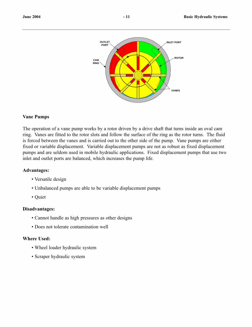
INLET PORT
ROTOR
OUTLETPORT
VANES
CAMRING
Vane Pumps
The operation of a vane pump works by a rotor driven by a drive shaft that turns inside an oval camring. Vanes are fitted to the rotor slots and follow the surface of the ring as the rotor turns. The fluidis forced between the vanes and is carried out to the other side of the pump. Vane pumps are eitherfixed or variable displacement. Variable displacement pumps are not as robust as fixed displacementpumps and are seldom used in mobile hydraulic applications. Fixed displacement pumps that use twoinlet and outlet ports are balanced, which increases the pump life.
Advantages:
• Versatile design
• Unbalanced pumps are able to be variable displacement pumps
• Quiet
Disadvantages:
• Cannot handle as high pressures as other designs
• Does not tolerate contamination well
Where Used:
• Wheel loader hydraulic system
• Scraper hydraulic system
June 2004 - 11 Basic Hydraulic Systems

CAM RING
CAM FOLLOWER
PISTON
VALVE
INTAKE
EXHAUST
FIXED DISPLACEMENT
INTAKE
EXHAUST
VARIABLE DISPLACEMENT
CONTROL LEVER
RETAININGPLATE
SWASHPLATE SWASH
PLATESLIPPER PISTON
BARRELASSEMBLY
DRIVESHAFT
Piston Pumps
Piston pumps operate by a piston reciprocating in a bore as the pump rotates. The piston draws fluid inas it retracts and expels fluid as it moves forward. Piston pumps can be either radial or axial, and bothstyles can be fixed or variable displacement. Fixed displacement axial piston pumps operate by using afixed position swashplate to control the output of the pistons. Variable displacement axial pistonpumps vary displacement by varying the angle of the swash plate. Radial piston pumps are typicallyvariable displacement and vary their displacement by moving a reaction ring to increase or decreasepiston travel.
Advantages:
• Capable of high speeds and high pressures
• Variable displacement capability
• Reduced horsepower draw
Disadvantages:
• More complex than vane or gear pumps
• Tightly machined surfaces demand clean hydraulic fluid
• High initial cost
• Does not tolerate contamination well
Where Used:
• Hydraulic Excavator hydraulic system
• Track Type Loader Hydrostatic drive system
• Backhoe Loader hydraulic system
June 2004 - 12 - Basic Hydraulic Systems

HYDRAULIC MOTORS
Hydraulic motors closely resemble hydraulic pumps in construction. They basically work the oppositeof a hydraulic pump. Instead of pushing on the fluid as the pump does, hydraulic motors are pushed bythe fluid and develop torque and continuous rotating motion. Hydraulic motors come in a variety ofconfigurations such as:
• Gear Motors – including external and internal gear
• Gerotor Motor
• Vane Motor
• Piston Motor – including axial and radial
June 2004 - 13 - Basic Hydraulic Systems

HYDRAULIC SYSTEMS
There are several different types of hydraulic systems. These systems differ primarily in the methodthat is used to control system flow and pressure.
Fixed Displacement System
A fixed displacement system is a simple hydraulic system where the output is proportional to the speedof the pump. Fixed displacement systems use a pump in which displacement cannot be altered. Thesepumps include gear, vane, fixed displacement piston, and gerotor.
Advantage:
• Simple system
• Low cost
• Responsive
Disadvantage:
• Inefficient
• Limited flow control
Where Used:
• Scraper hydraulic system
Load Sensing Hydraulic System
Load sensing hydraulic systems receive a signal from each implement circuit. The highest implementsignal pressure will control the output of the pump. In NEUTRAL there is no signal pressure and thepump is at standby. When an implement is activated, the signal pressure rises, causing the pump toincrease flow. The pump will increase flow based upon implement demand up to the capacity of thepump. When system demands exceed pump capacity, the function with the lowest pressure receivesthe most flow.
Advantages:
• Simple flow control
• Efficient
• Full hydraulic power on demand
• Reduced operator lever effort (for a single circuit)
• Improved fuel economy
June 2004 - 14 - Basic Hydraulic Systems
Disadvantage:
• Does not account for multiple function flow
• Complex signal network
• No operator sensation
Where Used:
• Backhoe loader hydraulic system
Pressure Compensation
Pressure compensation results in a constant implement speed for a given lever displacement. As theload on a non-compensated circuit varies, the speed of the cylinder will change due to the change in theload. With compensated circuits the implement speed stays the same. In other words, the circuit cycletime is the same with an empty bucket or with a fully loaded bucket. Pressure compensated controlvalves are typically part of a load sensing system.
Advantages:
• Simple flow control
• Efficient
• Full hydraulic power on demand
• Reduced operator lever effort for multiple, non-piloted circuit operation
• Accounts for multiple function flow in load sensing systems
Disadvantage:
• No proportional flow when flow demand exceeds maximum pump flow
• No operator sensation
Where Used:
• D5M and D6M Track-type Tractors
• D6R, D7R, D8R and D9R with Differential Steering
• D6R and D7R non-Differential Steering
• The loader control valves on Backhoe Loaders
June 2004 - 15 - Basic Hydraulic Systems
Proportional Priority Pressure Compensated (PPPC)
PPPC hydraulic systems operate similar to LSPC hydraulic systems except PPPC provides flow controlto each implement when the request by the operator exceeds the capacity of the pump. This systemallows the use of two different implements at the same time while controlling the flow of eachimplement automatically. For example, when an operator curls the bucket and the stick at the sametime and the flow needed exceeds the capacity of the pump, the system automatically slows down bothimplements proportionally.
Advantage:
• Implement proportional flow control
• Reduced operator lever effort
• Improved fuel economy
• Full power on demand
Disadvantage:
• Complex signal network
• Little operator feel
Where Used:
• Large Hydraulic Excavators (365/385)
• Wheel Hydraulic Excavators
• Motor Graders
• Telehandlers
June 2004 - 16 - Basic Hydraulic Systems

Negative Flow Control (NFC)
NFC hydraulic systems control pump output with a system flow signal instead of an implementpressure signal. An NFC system uses open center, parallel feed control valves. At standby, a portion ofthe pump oil flows through the open centers at the control valves. This oil is then supplied to anorifice. This orifice maintains a back pressure in the system, which regulates pump output. When oneor more of the control valves are shifted, this NFC signal will be reduced because flow through theopen center of the valve is being reduced. This causes the signal to the pump to decrease, and upstrokethe pump. NFC is a proportional signal, so less NFC pressure equals more pump output. This systemis primarily used in track type hydraulic excavators.
Advantage:
• Fast response
• Pump output based on flow demand
• Improved operator feel
• Simple control system
Disadvantage:
• Open center hydraulics cause heat
• Open center hydraulics have poor individual implement flow control
Where Used:
• Hydraulic Excavators (311-345)
June 2004 - 17 - Basic Hydraulic Systems1

HYDROSTATIC SYSTEMS
Hydrostatic systems take the mechanical rotary output of an engine or electric motor and convert it to ahydraulic source of power using a hydraulic pump. The hydraulic power is converted back tomechanical power using a hydraulic motor. This power can be used to drive a fan, transmission, pump,drive sprocket, wheel, or any other rotary device.
Open Loop Control
Open loop is the most basic form of hydrostatic hydraulic control. In this system the pump inlet oil iscompletely drawn from the hydraulic tank, the pump output is sent to drive the hydraulic motor, andthe return oil from the motor flows back to the tank.
Advantage:
• Works well for traveling at maximum speed.
Disadvantage:
• Does not compensate for changes in system
• Requires a large hydraulic reservoir
Where Used:
• Excavator travel system
• Excavator swing system
• Wheel Excavator travel system
Closed Loop Control
In a closed loop system, the return oil from the motor is sent directly to the pump inlet. Closed loopcompensates for load changes and friction, so that motions are more repeatable than with open loopsystems.
Advantage:
• Motions are more repeatable than with open loop systems
• Relatively small hydraulic reservoir
Disadvantage:
• Requires a charge pump to keep system full
• Requires some exchange of oil on the return side to dissipate heat from closed loop
June 2004 - 18 - Basic Hydraulic Systems

Where Used:
• Skid Steer Loaders
• D3G-D5G Track Type Tractors
• Large Track Loader
June 2004 - 19 - Basic Hydraulic Systems

CONTROL SYSTEMS
Control systems allow the operator to control the various functions of a machine while being stationedin the cab. Control systems can control the movement of the machine either manually or hydraulically.
Manual Controls
Manual controls refer to operator controls in the cab that are directly attached to the implement controlvalves by a mechanical linkage. When the mechanical linkage is moved by the operator, the valveinside the control valve assembly is shifted, which then moves the implement controlled by that valve.
Advantages:
• Provides the best operator feel
• Simpler system
Disadvantages:
• Higher operator fatigue
Pilot Controls
Pilot controls give the operator better control with less effort, which results in less operator fatigue.Pilot control valves send a low-pressure hydraulic signal from the control levers to the implementcontrol valve spools. The implement control spools control the flow of high-pressure oil. This allowsthe operator to easily move the levers to control pilot oil rather than moving a direct lever on thecontrol valve.
Advantages:
• Less operator fatigue
• Smaller operator controls
Disadvantage:
• Less operator feel
Electro-hydraulics
Electro-hydraulic control allows more accurate and faster control of machine implements. An electro-hydraulic system sensor or switch sends an electronic signal to an electro-hydraulic solenoid valve.The valve processes the information received electronically and outputs that information hydraulically.A good example would be traction control. A traction control system has a sensor on each wheel thatsenses wheel speed. When one wheel starts to spin, the sensor sends a signal to the electro-hydraulicvalve, which supplies fluid pressure to the brake on the slipping wheel.
June 2004 - 20 - Basic Hydraulic Systems
Advantage:
• Better control
Disadvantage:
• More complex control system
• No operator feel
Where Used:
• Transmission controls
• Telehandlers
June 2004 - 21 - Basic Hydraulic Systems

OTHER HYDRAULIC TERMS
Regeneration
Regeneration is a hydraulic circuit technique that takes hydraulic fluid from one end of the cylinder andcauses it flow to the other end of the cylinder to combine with the pump flow and increase speed of themovement, while decreasing the load on the system. Regeneration can also be referred to as the“Quick drop” function.
Advantage:
• Faster speeds
Disadvantage:
• More complex hydraulic system
Where Used:
• Hydraulic Excavators
• Track Type Tractors
• IT machines
• Backhoe Loaders with IT linkage
• Tractor Scrapers
Series Flow Hydraulic System
Series hydraulic flow supplies oil to the first control valve in the main control valve group. The valvesare open center directional control valves in the main control valve group, so the supply oil flowsthrough the first control valve to the second and so on before returning to the tank.
In a series directional control valve, when the valve is shifted the return oil from the circuit becomessupply oil to a circuit downstream. This feature allows multiple circuits to function at the same time.Currently, only a few machines are equipped with valves of this type and usually only for a singlecircuit for only one position of the directional spool. For example, this feature allows 953C-973CTrack Loaders to dump and raise the bucket at the same time.
June 2004 - 22 - Basic Hydraulic Systems1

Caterpillar uses interrupted series directional control valves rather than series directional control valves.When fully shifted, these valves direct return oil to the tank and not to a valve downstream. Thisaction prevents multiple valves from functioning at the same time. When a valve is only partiallyshifted, supply oil not used by the first activated valve is available for downstream valves. This featureprovides flow priority for one circuit over another. Some Caterpillar wheel loaders use this type ofsystem to allow tilt to have flow priority over the lift circuit. When the operator goes into the pile, hewill typically put the lift control lever into detent for full lift and then modulate the tilt control valve tomaximize the load in the bucket. With most of the flow going to the tilt valve the loader arms willmove slowly until the bucket is out of the pile, at which time the loader arms raise the bucket rapidly tothe maximum height in preparation for dumping the load into a haul truck.
Advantage:
• Can increase machine performance for some applications
Disadvantage:
• Multiple valve operation can be restricted
Where Used:
• 931-935 Traxcavator (series-type)
• 918F-928F Wheel Loaders (interrupted series-type)
• 924G-938G Wheel Loaders (interrupted series-type)
• 950G-972G Wheel Loaders (interrupted series-type)
• 933C-939C Track Loaders (tilt valve - Rackback and Dump)
• 953C-973C Track Loaders (tilt Valve - DUMP only)
Parallel Flow Hydraulic System
Parallel valves may be either open or closed center valves. Parallel hydraulic flow supplies oil to allvalves in the main control valve group at the same time. This allows each valve to receive flowregardless of the position of other valves. When two valves are fully activated simultaneously, the oilwill flow to the function that requires the least amount of pressure. No priority is given to any valve orfunction.
Advantage:
• Can operate two or more valves at once without flow loss to downstream valves
Disadvantage:
• The function that requires the lowest pressure will receive the most flow unless it is a PPPCsystem. Other circuits will operate slower.
June 2004 - 23 - Basic Hydraulic Systems
Where Used:
• Motor Graders• Telehandlers• Backhoe Loaders• D4H/D5H and D5M/D6M TTT• D3C-D5C Track-type Tractors• D3G-D5G Track-type Tractors• 902-908 Wheel Loader• 914G/IT14G Wheel Loader
Priority Flow Hydraulic System
Priority flow ensures that a function receives flow before flow is directed to other non-priorityfunctions. This is typically used for special work tools to ensure optimum operation, or tosteering/brake systems for safety reasons.
Advantage:
• Safety
• Critical circuits receive flow before all other circuits
Disadvantage:
• System is more complex
Where Used:
• Backhoe steering system
• Telehandler steering system
• Wheeled hydraulic excavator tool control, steering, and brake functions
June 2004 - 24 - Basic Hydraulic Systems