Hidden Winch Mount For 2011 Ford Super Duty Kit … · WARN 1 84314 Rev A0 INSTALLATION...
13
WARN 1 84314 Rev A0 INSTALLATION INSTRUCTIONS Hidden Winch Mount For 2011 Ford Super Duty Kit 84515 Your safety, and the safety of others, is very important. To help you make informed decisions about safety, we have provided installation and operating instructions and other information on labels and in this guide. This information alerts you to potential hazards that could hurt you or others. It is not possible to warn you about all potential hazards associated with this product, you must use your own good judgment. CARELESS INSTALLATION AND OPERATION CAN RESULT IN SERIOUS INJURY OR EQUIPMENT DAMAGE. READ AND UNDERSTAND ALL SAFETY PRECAUTIONS AND OPERATING INSTRUCTIONS BEFORE INSTALLING AND OPERATING THIS PRODUCT. This guide identifies potential hazards and has important safety messages that help you and others avoid personal injury or death. WARNING and CAUTION are signal words that identify the level of hazard. These signal words mean: WARNING signals a hazard that could cause serious injury or death, if you do not follow recommendations. CAUTION signals a hazard that may cause minor to moderate injury, if you do not follow recommendations. This guide uses NOTICE to call attention to important mechanical information, and Note: to emphasize general information worthy of special attention. WARNING INJURY HAZARD Failure to observe these instructions could lead to severe injury or death. Always use extreme caution when drilling on any vehicle. Make sure that all fuel lines, brake lines, electrical wires, and other objects are not punctured or damaged when/if drilling on the vehicle. Thoroughly inspect the area to be drilled (on both sides of material) prior to drilling, and relocate any objects that may be damaged. Failure to inspect the area to be drilled may result in vehicle damage, electrical shock, fire or personal injury. Always wear safety glasses when installing this kit. A drilling operation will cause flying material chips. Flying chips can cause eye injury. Always use extreme caution when cutting and trimming during fitting. Always remove jewelry and wear eye protection. Always insure components will remain secure and adequately supported during installation and operation. Always tighten all nuts and bolts securely, per the installation instructions. Always replace all worn or damaged parts before operating. Never operate this WARN product with damaged or missing parts. Notice Equipment Damage Always refer to the Operator’s Manual, supplied in the winch kit, for all wiring schematics and specific details on how to wire a WARN winch product to your vehicle. Read Operating Manual thoroughly.
Transcript of Hidden Winch Mount For 2011 Ford Super Duty Kit … · WARN 1 84314 Rev A0 INSTALLATION...

WARN 1 84314 Rev A0
INSTALLATION INSTRUCTIONS
Hidden Winch Mount
For 2011 Ford Super Duty
Kit 84515
Your safety, and the safety of others, is very important. To help you make informed decisions about safety, we have provided installation and operating instructions and other information on labels and in this guide. This information alerts you to potential hazards that could hurt you or others. It is not possible to warn you about all potential hazards associated with this product, you must use your own good judgment. CARELESS INSTALLATION AND OPERATION CAN RESULT IN SERIOUS INJURY OR EQUIPMENT DAMAGE. READ AND UNDERSTAND ALL SAFETY PRECAUTIONS AND OPERATING INSTRUCTIONS BEFORE INSTALLING AND OPERATING THIS PRODUCT. This guide identifies potential hazards and has important safety messages that help you and others avoid personal injury or death. WARNING and CAUTION are signal words that identify the level of hazard. These signal words mean:
WARNING signals a hazard that could cause serious injury or death, if you do not follow recommendations.
CAUTION signals a hazard that may cause minor to moderate injury, if you do not follow recommendations.
This guide uses NOTICE to call attention to important mechanical information, and Note: to emphasize general information
worthy of special attention.
WARNING
INJURY HAZARD
Failure to observe these instructions could lead to severe injury or death. � Always use extreme caution when drilling on any vehicle. Make sure that all fuel lines, brake lines, electrical wires, and other objects are
not punctured or damaged when/if drilling on the vehicle. Thoroughly inspect the area to be drilled (on both sides of material) prior to drilling, and relocate any objects that may be damaged. Failure to inspect the area to be drilled may result in vehicle damage, electrical shock, fire or personal injury.
� Always wear safety glasses when installing this kit. A drilling operation will cause flying material chips. Flying chips can cause eye injury. � Always use extreme caution when cutting and trimming during fitting. � Always remove jewelry and wear eye protection. � Always insure components will remain secure and adequately supported during installation and operation. � Always tighten all nuts and bolts securely, per the installation instructions. � Always replace all worn or damaged parts before operating. � Never operate this WARN product with damaged or missing parts.
Notice
Equipment Damage � Always refer to the Operator’s Manual, supplied in the winch kit, for all wiring schematics and
specific details on how to wire a WARN winch product to your vehicle.
Read Operating Manual thoroughly.

WARN 2 84314 Rev A0
This WARN Hidden Winch Mount is designed to handle WARN Large Frame Winches up to 16,500 lb capacity.
Before You Begin - Read and understand these Installation Instructions.
- Refer to Figure A to become familiar with the components and hardware in this kit.
PARTS LIST
TORQUE SPECIFICATIONS
BOLT SIZE TORQUE 3/8 inch 30 lb. ft (40.7 N-m)
7/16 inch 50 lb. ft. (67.8 N-m)
1/2 & 5/8 inch 75 lb. ft. (101.7 N-m)
Fig A - Bracket Installation Exploded View
PART NO. QUANTITY DESCRIPTION
84516 1 Winch Carrier
78313 1 LH Frame Extension
78314 1 RH Frame Extension
84488 1 M15000 Control Pack Bracket
78451 1 LH Bumper Brace Bracket
78453 1 RH Bumper Brace Bracket
84783 1 16.5Ti Control Pack Bracket
78864 1 License Plate Bracket
84511 1 Hardware Kit for Hidden Winch Kit

WARN 3 84314 Rev A0
Figure B - Winch Mount Installation Exploded View
Figure C- 16.5Ti Solenoid Pack Bracket
Figure D: Control Pack Bracket (All except 16.5Ti)

WARN 4 84314 Rev A0
Vehicle Disassembly
1. Disconnect the fog lamps if equipped.
2. Detach any other wires or cables that are connected to the bumper such as block heater cables. Remove and
discard the rubber air deflector flap if applicable.
3. Remove and discard the front license plate and bracket if equipped.
4. Remove the bolts attaching the bumper end brackets to the frame. The brackets should be left in place on the
bumper. See Figure 1
Figure 1: LH Bumper Bracket Bolt
5. Remove the (4) front mounting bolts (2 outboard of each tow loop) and remove the bumper. Place the bumper
face down on a protective surface. The bolts and nut plates will be reinstalled later. See Figure 2
Figure 2: LH Front Bumper Bolts
6. Remove the (3) bolts securing each tow loop/bumper bracket to the frame. Remove the tow loops. Note left
and right tow loops for later installation.
Skirt Kit Installation (optional): If you are installing the optional Skirt Kit you should do so now. Using
clamps as shown in the following pictures will ease assembly and improve alignment of all plastic skirt parts.
Remove Bumper Bolts
(2 per side)
Remove
Bumper
Bolts
WARN 5 84314 Rev A0
7. Remove OEM Bumper Tread Caps from top of bumper. Use fingers or pliers to squeeze retainer tabs and push
retainers through slots in bumper. Bumper cap treads will not be reinstalled.
Figure 3: Bumper Tread Caps
8. Place center skirt piece on bumper and install outer pine tree fasteners through holes and into slots in bumper.
Align the center piece to match the countour of the bumper and clamp in place.
Figure 4: Pine Tree Fastener Example.
9. Mark hole locations on skirt flange for holes shown in Figure 5.
Figure 5: Bumper Flange hole location. (Driver side shown)
Bumper Tread Caps
Pine Tree Fastener
Outer Fastener Hole (1 fastener each end)

WARN 6 84314 Rev A0
10. Remove pine tree fasteners and the center skirt piece (discard pine tree fasteners) and drill 5/16” holes
through each of the locations marked in step 9.
11. Reinstall the center skirt piece and install 5 pine tree fasteners through holes in front edge and into slots in
bumper. Press firmly to insure a tight fit. Align center skirt piece to match bumper contours.
Figure 6: Pine tree fastener locations.
12. Install 1/4” hardware in each hole. Use 1/4” flat washers on both sides of the holes. It is only necessary to
“snug” these fasteners. Over tightening will fracture the plastic Skirt.
Figure 7: ¼-20x3/4” Fastener. (Driver side shown)
13. Install the top bumper caps and hold in place with 2 pine tree fasteners each.
Figure 8: Top Cap Pine Tree Fastener installed.
14. Install clamps as shown in Figure 9 and align panels for best appearance and alignment.
Pine Tree Fasteners
Pine Tree Fasteners

WARN 7 84314 Rev A0
Figure 9: Clamp Top Cap to Center Skirt Piece.
15. Drill 5/16” holes through flanges of top cap and center piece.
16. Install 1/4” hardware in each hole. Use 1/4” flat washers on both sides of the holes. It is only necessary to
“snug” these fasteners. Over tightening will fracture the plastic Skirt.
Figure 10: Fasteners installed.
17. Drill two 1/4” holes through the flanges in the each end of the bumper. Holes should be about 3” to 4” apart
and be centered between the outer and inner edges of the flange.
18. Clamp bumper end caps onto the end of the bumper and align to match top caps for best appearance.
19. Mark bumper hole locations on end cap flange.
Figure 11: Mark End Cap hole locations from backside.
20. Remove end caps and drill 5/16” holes at locations marked in step 19.
21. Clamp bumper end caps back onto bumper end and align as in step 18.
22. Drill a 5/16” hole through top flange of each end cap and the flange of each top cap. See figure 12.
¼-20 Fasteners
Mark Hole Locations
WARN 8 84314 Rev A0
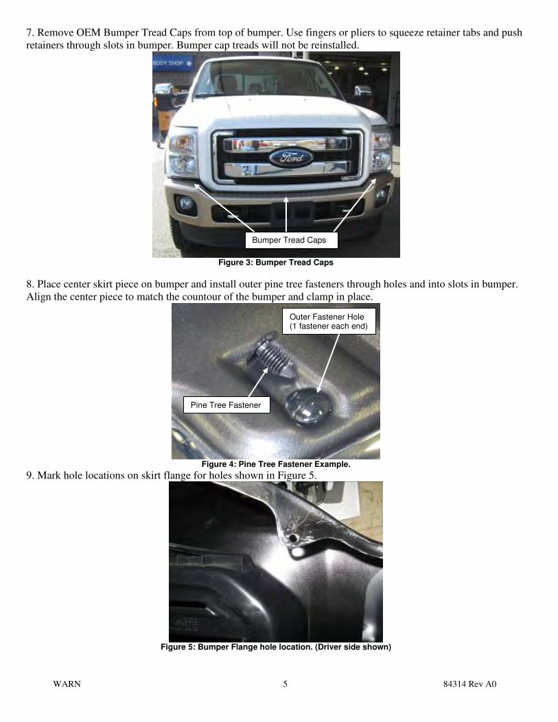
Figure 12: End Cap Installation. (Bumper flange holes not shown)
23. Install 1/4” hardware in each hole. Use 1/4” flat washers on both sides of the holes. It is only necessary to
“snug” these fasteners. Over tightening will fracture the plastic Skirt.
Hidden Winch Mount Installation
24. Hold each Frame Extension bracket in place on the frame. Install a 5/8 x 1 1/2” bolt with flat washer through
each of the rear holes into the slots in the side of the frame. Thread the bolts into special 5/8” nuts-with-handles
inside the frame. Do not tighten yet.
Figure 13: LH frame rail
25. Install a 1/2 x 1 1/2” bolt with flat washer through the front Frame Extension hole into the hole in the side of
the frame. Install a 1/2” nut, lock washer and flat washer inside the frame. Do not tighten yet.
26. Install (3) 1/2 x 2” bolts with flat washers through each Frame Extension into the tow loop holes in the top of
the frame. Install 1/2” flat washer, lock washers and nuts. Do not tighten yet.
NOTE: The frame holes are sized for metric fasteners. It may be necessary to enlarge some of these holes to fit a
1/2” bolt.
27. Install the remote extension cable onto carrier using 2 each #10-24x1” machine screws, washers, lock
washers and nuts. (See Figure B)
Insert 5/8” bolts
through Frame
Extension into
these slots
Hole location for Step 21.

WARN 9 84314 Rev A0
Figure 14: LH Frame Extension bolted in place
28. Install the winch in the carrier before installing the carrier onto the truck. Use care not to damage remote
extension cable when placing winch into carrier.
29. Place the winch in the Carrier and feed the wire rope through the opening in the front of the Winch Carrier.
30. Install the hardware, provided with the winch, in all six (6) winch mounting holes. The bottom front bolts
will be installed from inside the fairlead extension bracket. Tighten to the recommended torque. See Figure 15.
NOTE: Remove the control pack from the winch if it is installed. It will be remote mounted behind the
carrier.
Figure 15: LH Frame Extension bolted in place
31. With assistance hold the Winch Carrier in position and insert 7/16 x 1-1/4” bolts with flat washers through
the (4) slots in the Frame Extension and through the Winch Carrier holes. Install 7/16” lock washers and nuts on
passenger side. Install the bolts into the provided “V” nut plate on the driver side. The “handle” should point
upwards when installed correctly. Install 7/16” lock washers and nuts on the bottom bolt. Do not tighten yet.
NOTE: It is important to use the correct bolt lengths in these holes. Bolts longer than specified can
interfere with the winch motor and prevent proper winch alignment.
NOTE: If bolt contacts motor end cap add another washer under the bolt head until bolt no longer
contacts motor.
(3) ½ x 2” bolts
through original tow
loop holes in frame
LH frame
Extension
Original
tow loop
½ x 1-1/2” bolt
into frame
7/16 x 1 1/4” bolt
Fairlead Extension Bracket
WARN 10 84314 Rev A0
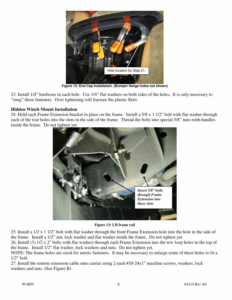
Figure 16: Winch Carrier installed.
32. Install a 7/16 x 1-1/4” bolt and flat washer through each slot located in the lower flange of the Winch Carrier
and through the slots in the Frame Extensions. Install 7/16” flat washers, lock washers and nuts. Do not tighten
yet.
Figure 17 LH Lower Carrier flange
33. Winch Carrier should be left bottomed on the bolts through the Frame Extensions and tighten the 7/16”
hardware to the recommended torque, starting with the side bolts and ending with the (4) Carrier lip bolts.
NOTE: Due to vehicle tolerances the clutch lever may contact the grille slightly in the engaged position.
The contact is minor and should be considered normal. If desired, a small amount of the grille may be cut
away to eliminate the contact.
34. Center the Winch Carrier and tighten the (6) 1/2” bolts installed in the tow loop holes, to the recommended
torque.
35. Tighten the (2) 1/2” frame bolts to recommended torque.
36. Tighten the (4) 5/8” frame bolts to the recommended torque.
“V” nut plate between
motor and carrier.
7/16 x 1 1/4” bolt
7/16 x 1 1/4” bolts

WARN 11 84314 Rev A0
37. Position the original tow loop/bumper brackets on top of the Frame Extensions. Make sure they are on the
correct sides. Install the (6) original tow loop bolts through the bottom of the Frame Extensions and into the tow
loops. Do not tighten yet. See Figure 14.
Figure 18:Fairlead Mounting Holes.
38. Attach the control pack bracket to the inside of the LH frame rail using the 5/8-11 x 1 ½” bolt, flat washer,
lock washer and nut. Insert the ½-13x 1 ½” bolt, flat washer, lock washer and nut. Do not tighten yet.
NOTE: The 16.5Ti uses the smaller of the two brackets. The larger bracket is for all other control packs.
Figure 19: Bracket installation.
39. Attach the control pack to the bracket. 16.5Ti is mounted using the slots in the cast aluminum housing and
(2) 7/16-14x1 ¼” cap screws, washers, lock washers and nuts. The other control packs are attached using the ¼”
fasteners protruding from the back. Remove the extra ¼” nut from each bolt and insert screws through the bracket
then reinstall the nuts. Adjust height of control pack and tighten all fasteners. NOTE: Leave a minimum ½”
clearance between the control pack and the bottom of radiator.
NOTE: The M12000 winch control pack will need to be opened and 1/4” x 1” bolts inserted through the
hole and slot in the center of the control pack backing plate. Attach the control pack using ¼” washers and
nuts. Adjust and tighten the fasteners then reinstall the cover.
Figure 20: Control pack and Bracket Installation. (16.5Ti shown)
Winch and fairlead
mounting holes
7/16 x 1 1/4” bolts
here
Auxiliary fairlead
mounting holes
5/8x1 ½ Bolt
1/2x1 ½ Bolt

WARN 12 84314 Rev A0
40. Reattach motor cables and route winch ground and power cable to battery area but do not connect to battery
until kit installation is complete. Attach the remote extension cable to the control pack remote plug in. Note:
Adjust the cable positions to remove kinks and twists in motor cables. Retighten motor cables and reinstall
boots over the motor terminals. 41. Place the bumper into position. Lift the bumper so the top bumper flange fits over the top winch mounting
bolts of the Winch Carrier. The bumper can then be rotated into place so the fairlead mounting surface extends
through the opening in the bumper.
NOTE: The Skirt is attached to the bumper so use caution when installing the bumper to avoid damaging
the skirt. Never attempt alone. Skirt parts can be removed if needed to ease installation but attaching
fasteners and aligning the pieces will be more difficult.
42. Install the (4) original front bumper bolts and nut plates through the bumper, ¼” spacer and tow/bumper
brackets. Center and level the bumper and tighten the hardware.
Figure 21: Bumper installed and leveled.
43. Install the (2) 7/16” button head cap screws through the holes in the skirt and into the top winch holes. The
fasteners should be “snugged”, do not torque, to avoid cracking and damaging the skirt..
Figure 22: RH Skirt Button Head Cap Screw Installed
7/16 Button Head
Cap Screw with
lock washer

WARN 13 84314 Rev A0
44. Install the Bumper Brace Brackets on the Frame Extension flange. Attach the factory bumper end brackets to
the Bumper Brace Brackets. Use the 3/8” hardware at both ends. Tighten to recommended torque. (See Figure
B for details)
Figure 23: Bumper Brace Installation
45. Feed the wire rope through the Fairlead and install it using the 7/16 x 1 1/4” bolts, lock and flat washers. If
you are installing a front license plate, place the License Plate Bracket provided between the Fairlead and the
Carrier before tightening the hardware. Tighten to the recommended torque. If the Fairlead has two mounting
slots per side, align the center slots to the bottom holes in the fairlead extension bracket. Install this type of
Fairlead with the second set of slots above the centered slots. The mounting hardware is included with this kit.
NOTE: Install fairlead with warning label on the top.
46. Reconnect the fog lamps. Install the license plate (if applicable) below the fairlead, on the bracket installed
earlier. Re-attach or secure any wires or cables previously disconnected. Attach winch power cables to battery
per instructions included with winch.
47. Use tie wraps to connect any excess wires or cables securely to the vehicle. Things to consider: Engine block
heater plug, power and ground cables and remote extension cable.
48. The mounting kit installation is complete. Refer to the Winch Operator’s Manual to complete the winch
installation.
Figure 23: Fairlead and bumper installed
WARNING
PERFORM REGULAR INSPECTIONS ON THE WINCH, WINCH MOUNT, AND RELATED
HARDWARE. NEVER OPERATE THE WINCH OR WINCH MOUNT WITH DAMAGED OR
MISSING PARTS. FAILURE TO FOLLOW THIS WARNING MAY CAUSE VEHICLE
DAMAGE AND OPERATOR INJURY OR DEATH.
3/8 Bolts, Washers, Lock Washers and nuts. (3 per side)