
hiad_2
15
Hypersonic Inflatable Aerodynamic Decelerator (HIAD) Technology Development Overview Stephen J. Hughes 1 , Dr. F. McNeil Cheatwood 2 , Dr. Anthony M. Calomino 3 , Henry S. Wright 4 , Mary Elizabeth Wusk 5 , and Monica F. Hughes 6 NASA Langley Research Center Email: [email protected], [email protected], [email protected], [email protected], [email protected] , Monica.F.Hughes @nasa.gov The successful flight of the Inflatable Reentry Vehicle Experiment (IRVE)-3 has further demonstrated the potential value of Hypersonic Inflatable Aerodynamic Decelerator (HIAD) technology. This technology development effort is funded by NASA’s Space Technology Mission Directorate (STMD) Game Changing Development Program (GCDP). This paper provides an overview of a multi-year HIAD technology development effort, detailing the projects completed to date and the additional testing planned for the future. The effort was divided into three areas: Flexible Systems Development (FSD), Mission Advanced Entry Concepts (AEC), and Flight Validation. FSD consists of a Flexible Thermal Protection Systems (FTPS) element, which is investigating high temperature materials, coatings, and additives for use in the bladder, insulator, and heat shield layers; and an Inflatable Structures (IS) element which includes manufacture and testing (laboratory and wind tunnel) of inflatable structures and their associated structural elements. AEC consists of the Mission Applications element developing concepts (including payload interfaces) for missions at multiple destinations for the purpose of demonstrating the benefits and need for the HIAD technology as well as the Next Generation Subsystems element. Ground test development has been pursued in parallel with the Flight Validation IRVE-3 flight test. A larger scale (6m diameter) HIAD inflatable structure was constructed and aerodynamically tested in the National Full-scale Aerodynamics Complex (NFAC) 40ft by 80ft test section along with a duplicate of the IRVE-3 3m article. Both the 6m and 3m articles were tested with instrumented aerodynamic covers which incorporated an array of pressure taps to capture surface pressure distribution to validate Computational Fluid Dynamics (CFD) model predictions of surface pressure distribution. The 3m article also had a duplicate IRVE-3 Thermal Protection System (TPS) to test in addition to testing with the Aerocover configuration. Both the Aerocovers and the TPS were populated with high contrast targets so that photogrammetric solutions of the loaded surface could be created. These solutions both refined the aerodynamic shape for CFD modeling and provided a deformed shape to validate structural Finite Element Analysis (FEA) models. Extensive aerothermal testing has been performed on the TPS candidates. This testing has been conducted in several facilities across the country. The majority of the testing has been conducted in the Boeing Large Core Arc Tunnel (LCAT). HIAD is continuing to mature testing methodology in this facility and is developing new test sample fixtures and control methodologies to improve understanding and quality of the environments to which the samples are subjected. Additional testing has been and continues to be performed in the 1 HIAD Chief Engineer, Systems Engineering Directorate (SED)/Mechanical Systems Branch, NASA LaRC/MS432 2 EDL Principle Investigator, Office of Chief Technologist, NASA LaRC/MS250 3 HIAD Associate Principle Investigator, Flexible Systems Development, SED/Atmospheric Flight and Entry Systems Branch, NASA LaRC/MS489 4 HIAD Deputy PI, SED/ Atmospheric Flight and Entry Systems Branch, NASA LaRC/MS489 5 HIAD Project Manager, Space Technology and Exploration Directorate (STED), NASA LaRC/MS494 6 HIAD Manager, Flexible System Development, STED, NASA LaRC/MS489
-
Upload
hrishikesh-joshi -
Category
Documents
-
view
26 -
download
3
description
hiad_2
Transcript of hiad_2

Hypersonic Inflatable Aerodynamic Decelerator (HIAD) Technology Development Overview
Stephen J. Hughes1, Dr. F. McNeil Cheatwood2, Dr. Anthony M. Calomino3, Henry S. Wright4,
Mary Elizabeth Wusk5, and Monica F. Hughes6 NASA Langley Research Center
Email: [email protected], [email protected], [email protected], [email protected], [email protected] , Monica.F.Hughes @nasa.gov
The successful flight of the Inflatable Reentry Vehicle Experiment (IRVE)-3 has further
demonstrated the potential value of Hypersonic Inflatable Aerodynamic Decelerator (HIAD) technology. This technology development effort is funded by NASA’s Space Technology Mission Directorate (STMD) Game Changing Development Program (GCDP). This paper provides an overview of a multi-year HIAD technology development effort, detailing the projects completed to date and the additional testing planned for the future.
The effort was divided into three areas: Flexible Systems Development (FSD), Mission Advanced Entry Concepts (AEC), and Flight Validation. FSD consists of a Flexible Thermal Protection Systems (FTPS) element, which is investigating high temperature materials, coatings, and additives for use in the bladder, insulator, and heat shield layers; and an Inflatable Structures (IS) element which includes manufacture and testing (laboratory and wind tunnel) of inflatable structures and their associated structural elements. AEC consists of the Mission Applications element developing concepts (including payload interfaces) for missions at multiple destinations for the purpose of demonstrating the benefits and need for the HIAD technology as well as the Next Generation Subsystems element.
Ground test development has been pursued in parallel with the Flight Validation IRVE-3 flight test. A larger scale (6m diameter) HIAD inflatable structure was constructed and aerodynamically tested in the National Full-scale Aerodynamics Complex (NFAC) 40ft by 80ft test section along with a duplicate of the IRVE-3 3m article. Both the 6m and 3m articles were tested with instrumented aerodynamic covers which incorporated an array of pressure taps to capture surface pressure distribution to validate Computational Fluid Dynamics (CFD) model predictions of surface pressure distribution. The 3m article also had a duplicate IRVE-3 Thermal Protection System (TPS) to test in addition to testing with the Aerocover configuration. Both the Aerocovers and the TPS were populated with high contrast targets so that photogrammetric solutions of the loaded surface could be created. These solutions both refined the aerodynamic shape for CFD modeling and provided a deformed shape to validate structural Finite Element Analysis (FEA) models.
Extensive aerothermal testing has been performed on the TPS candidates. This testing has been conducted in several facilities across the country. The majority of the testing has been conducted in the Boeing Large Core Arc Tunnel (LCAT). HIAD is continuing to mature testing methodology in this facility and is developing new test sample fixtures and control methodologies to improve understanding and quality of the environments to which the samples are subjected. Additional testing has been and continues to be performed in the
1 HIAD Chief Engineer, Systems Engineering Directorate (SED)/Mechanical Systems Branch, NASA LaRC/MS432 2 EDL Principle Investigator, Office of Chief Technologist, NASA LaRC/MS250 3 HIAD Associate Principle Investigator, Flexible Systems Development, SED/Atmospheric Flight and Entry Systems Branch, NASA LaRC/MS489 4 HIAD Deputy PI, SED/ Atmospheric Flight and Entry Systems Branch, NASA LaRC/MS489 5 HIAD Project Manager, Space Technology and Exploration Directorate (STED), NASA LaRC/MS494 6 HIAD Manager, Flexible System Development, STED, NASA LaRC/MS489

NASA LaRC 8ft High Temperature Tunnel, where samples up to 2ft by 2ft are being tested over representative underlying structures incorporating construction features such as sewn seams and through-thickness quilting.
With the successful completion to the IRVE-3 flight demonstration, mission planning efforts are ramping up on the development of the HIAD Earth Atmospheric Reenty Test (HEART) which will demonstrate a relevant scale vehicle in relevant environments via a large-scale aeroshell (~8.5m) entering at orbital velocity (~7km/sec) with an entry mass on the order of 4MT. Also, the Build to Print (BTP) hardware built as a risk mitigation for the IRVE-3 project to have a “spare” ready to go in the event of a launch vehicle delivery failure is now available for an additional sub-orbital flight experiment. Mission planning is underway to define a mission that can utilize this existing hardware and help the HIAD project further mature this technology.
Nomenclature 8ft HTT = NASA LaRC 8 Foot High Temperature Tunnel °C = centigrade ACS = Attitude Control System AEC = Advanced Entry Concepts AoA = Angle of Attack BET = Best Estimated Trajectory BBXI = Black Brant XI cg = center of gravity CFD = Computational Fluid Dynamics FEA = Finite Element Analysis FSD = Flexible Systems Development FTPS = Flexible Thermal Protection System HEART = HIAD Earth Atmospheric Reentry Test HIAD = Hypersonic Inflatable Aerodynamic Decelerator IAD = Inflatable Aerodynamic Decelerator IRVE = Inflatable Reentry Vehicle Experiment IS = Inflatable Structures LCAT = Boeing Large Core Arc Tunnel LEO = Low Earth Orbit m = meter MCR = Mission Concept Review MEDLI = Mars Science Laboratory Entry/Descent/Landing Instrumentation MPCV = Multi-Purpose Crew Module MT = Metric ton NFAC = National Full-scale Aerodynamics Complex NIACS = NSROC Inertial Attitude Control System NSROC = NASA Sounding Rocket Operations Contract OCT = Office of Chief Technologist PBM = Physics Based Model PCM = Pressurized Cargo Module SiC = Silicon Carbide SRI = Southern Research Institute TPS = Thermal Protection System UPWT = Unitary Plan Wind Tunnel WFF = Wallops Flight Facility

I. Introduction The successful flight of the Inflatable Reentry Vehicle Experiment (IRVE)-3 (reference 1) has further
demonstrated the potential value of Hypersonic Inflatable Aerodynamic Decelerator (HIAD) technology. This technology development effort is funded by NASA’s Space Technology Mission Directorate (STMD) Game Changing Development Program (GCDP). The HIAD technology development was divided into three areas: Flexible Systems Development (FSD), Advanced Entry Concepts, and Flight Validation (see figure 1). This paper provides an overview of a multi-year HIAD technology development effort, both the projects completed to date and the additional testing planned for the future.
Figure 1HIAD Project Organizational Structure
II. HIAD Project As stated earlier HIAD was divided into three areas: Flexible Systems Development (FSD),
Advanced Entry Concepts (AEC), and Flight Validation. FSD was divided into two elements a Flexible Thermal Protection System (FTPS) element and an Inflatable Structures (IS) element. The FTPS effort focuses on manufacturing processes for TPS materials and assemblies, material thermal response properties over the range of environments in which the materials have to operate, incorporating those material properties into a physics based model to predict the thermal response to the applied aerothermal heating environment, Computational Fluid Dynamics (CFD) simulation to determine the correct environment to apply in aerothermal heating facilities to replicate the design flight environment, and finally aerothermal performance testing to subject instrumented materials to the environments proving capabilities of the materials and providing data to verify the physics based response models. The IS effort focuses on manufacturing processes for IS materials and assemblies, material structural response properties over the range of environments in which the materials have to operate, incorporating those material properties into a Finite Element Analysis (FEA) to predict the load and deflection response to the applied environment, Computational Fluid Dynamics (CFD) simulation to determine the correct environment to apply to the structure to simulate the design flight environment, and finally performance

testing to subject instrumented inflatable structures to the environments proving capabilities of the materials and providing data to verify the FEA. The AEC effort is divided into the Mission Application Trade Studies and Next Generation Subsytems. Mission Apps is developing concepts (including payload interfaces) for missions at multiple destinations for the purpose of demonstrating the benefits and need for the HIAD technology. Next Gen is investigating methods for generating lift on blunted cones focusing on aerodynamic trim surfaces. Flight Validation efforts up until this point had been focused on the IRVE-3 flight and the associated data reduction. A flight spare unit of the IRVE-3 centerbody hardware, referred to as Build to Print (BTP), was built as a risk reduction to have hardware available in the event of an IRVE-3 launch vehicle failure. This unit is now available for a new mission and is being proposed as a new start mission to OCT, IRVE-4. Additional flight validation work has been performed in support of the HIAD Earth Atmospheric Reentry Test (HEART) a proposed HIAD which leverages the Orbital Sciences Cygnus Pressurized Cargo Module (PCM) as ballast as part of an entry demonstration flight test, resulting in achieving a TRL7 for HIAD entry technologies.
III. FSD - FTPS FTPS development1 has progressed significantly in the two years since the last ADS conference.
Thermal and structural property tests have been performed for many candidate materials over a range of temperatures and pressures at both Southern Research Institute (SRI) and in-house test facilities at NASA LaRC and GRC. TPS layups have been mechanically aged at SRI to determine if there is any problematic degradation in material response properties after being hard packed, environmentally cycled and deployed. Aerothermal tests have been performed on various candidate layups in many configurations. Testing has been performed on large 2ft by 2ft samples in the 8ft High Temperature Tunnel, a vitiated flow blow down facility at NASA LaRC, but the Boeing Large Core Arc Tunnel (LCAT) has become the workhorse aerothermal test facility for the HIAD project. A custom designed shear wedge fixture (See Figure 2) was developed and used for many material candidate layups at a range of test conditions. Difficulties getting the HIAD physics based thermal performance model predictions to match tested layup temperatures caused the project to re-evaluate the test approach. As a result, a decision was made to change to stagnation testing to help achieve model correlation by reducing the number of environment variables. A stagnation test fixture (see Figure 3) was designed based on the outer mold line of a test fixture extensively used at LCAT by the Mars Science Laboratory Entry/Descent/Landing Instrumentation (MEDLI) project. Stagnation testing revealed an issue with the heat flux distribution across the test sample surface in the new stagnation model holder. The outer sample plies were melting at the perimeter at fluxes previously survived in the shear fixture and laser heating tests. CFD modeling of the test setup indicated there was roughly a 25% rise in heat flux from the center of the sample to the sample perimeter in the current stagnation configuration. Working with the LCAT personnel the stagnation sample holder was redesigned (see Figure 4) and heat flux variation across the face of the sample was cut to approximately 10%. Additionally LCAT personnel, Matt Kardell and John Simms, developed the control to run heating profiles in the LCAT to match preliminary HEART design simulation trajectory heating profiles (see Figure 5). This capability was a significant improvement over the traditional square pulse heating approach because the FTPS materials respond much more favorably to realistic profile heating than to a square pulse. As a result of these two improvements, materials that would have been classified as incapable of sustaining a 40W/cm2 heat rate survive heating profiles with peak heating in excess of 50W/cm2. Finally, aerothermal testing of the full scale IRVE-3 nose assembly was performed in the JSC Test Position 2 arc jet (see Figure 6). Two build to print copies of the flight

nose TPS assembly were tested at heating rates far in excess of the IRVE-3 predicted peak flight heating rate as well as heat load. To address scalability concerns an FTPS was designed with the current baseline materials to be integrated with a 6m stacked torus inflatable structure and is currently under construction. An FTPS physics based thermal response model has been under development incorporating the material thermal properties as they are acquired in testing. Sufficient thermo-physical phenomena and property data are now incorporated in the model to demonstrate reasonable agreement between model ply temperature predictions and aerothermal testing data for the baseline FTPS layup.
Figure 4 LCAT Redesigned 4.5in Stagnation Fixture
Figure 2 LCAT Shear Fixture
Figure 3 LCAT 3.5in Stagnation Fixture

Future FTPS development will include aerothermal testing of the sample layups mechanically aged at SRI. Development will also continue on next generation materials. The most pressing material development is with the outer cloth. The latest trajectory simulation and CFD modeling of the HEART design mission are indicating the aerothermal heating environment may be in excess of what the baseline outer material, BF20, is capable of surviving. The replacement candidate, SiC, is an excellent aerothermal performer, but needs to increase technical maturity in the areas of manufacturing the base cloth, construction (stitching and joining) of the FTPS assembly, and mechanical durability to withstand the rigors of construction, packing, and deployment. Additionally, a sub scale 3m assembly of the next generation FTPS is planned for FY2014.
LCAT Run 2530 - 27 February 2013Arc Parameters
0
5
10
15
20
25
30
35
40
45
50
55
60
65
70
500 600 700 800 900 1000 1100
Time (sec.)
Hea
t Flu
x (W
/cm
^2)
0
1
2
3
4
5
6
7
8
9
10
11
12
13
14
Stag
natio
n Pr
essu
re (k
Pa),
Inte
grat
ed H
eat L
oad
(kJ/
cm^2
) & V
olts
q-stag q-stag target P-stag P-stag targetP&H Driver Volts Proportion Air Volts Badger Valve Volts Integrated Heat Load
11.74 kJ/cm^2
Figure 5 LCAT Profile Heat and Pressure Pulse
Figure 6 IRVE-3 Nose Assembly in JSC TP2

IV. FSD - IS
Figure 7 NFAC 40x80 Test Section with 6m HAID Test Article
The IS technical development has progressed as well in the two years since the last ADS conference. Uni-axial load testing at temperature has been conducted on all candidate materials and several potential next generation materials. 3m and 6m diameter IS assemblies have been manufactured and aerodynamically tested in the 40ftx80ft circuit of the National Fullscale Aerodynamics Complex (NFAC) at Ames Research Center (see Figure 7)2. Instrumentation has been developed to measure loads in the strap assemblies3 and a photogrammetric measurement system has been adapted for use with these high-drag blunt bodies in the NFAC 40x80 test section4. Extensive effort has been expended to reduce and post-process the photogrammetric data5 so that these data can be utilized to create deformed model geometry for CFD grid generation and for comparison to FEA predicted displacements. Data from the strap load cells have been used to help refine the structural model. The challenges of modeling the complexities of a stacked torus assembly have lead the project to take a step back and perform simple elemental testing in an effort to assure that the HIAD FEA can predict simpler single element tests. A series of straight air-beams with three different bias braid angles were manufactured in order to study the effect of braid angle on structural response as well as demonstrating that the project can verify that the FEA is accurately modeling the behavior of the constitutive elements. The straight beams will be used in 4-point bending and tension torsion testing. Additionally, several individual tori are being manufactured at three different major diameters with the same bias braid angle and axial cord strength to try and capture any effects of scaling. For one of the major diameters an additional test article is being constructed with a different bias braid angle and another test article is being constructed with lighter weight axial cord. The individual tori will be subjected to a radially inward (compressive) load and a combination of inward load and torsion. Again the effort is to verify the FEA accurately predicts the behavior of the element. New instrumentation is being developed for the elemental testing to make it possible to measure the strain in the axial cords during load testing. This instrumentation will allow the project to verify hypotheses about

how the level of axial cord load affects the structural response of the torus. The instrumentation being developed is elastomeric and has the possibility of being tolerant of packing and deployment, potentially making the instrumentation applicable for in-flight measurement.
Figure 9 Preliminary Design Elemental Test Article Toroid Compression/Torsion Fixture
IS has also continued to advance the temperature capability of the inflatable structure in an effort to reduce overall aeroshell system mass by reducing the quantity of TPS insulation required. The effort requires both a higher temperature capable fiber for the construction of the bias braid, axial cord, and suspension webbing as well as a higher temperature film for the inflatable bladder liner. IS has two leading fiber candidates, graphite and PBO. Load tests at temperature have been completed for identical construction webbing from the two candidate materials. The PBO webbing has roughly 70% reduction strength at 400C, but even with that reduction is more than adequate to carry the required loads. The graphite only experiences roughly a 20% reduction in load, but is below the required load capacity. Discussions are underway with the narrow goods weaver to attempt to improve the initial strength of the
Figure 8 Elemental Straight Beam Hydrostatic Test Article

graphite webbing to take advantage of the higher temperature capability of the fiber. The leading bladder liner candidate is an elastic polyimide film, Essar Stretch. The manufacturer reports use temperatures in excess of 400C and allowable elongation over 80%. High temperature testing of the Essar Stretch is currently underway at NASA LaRC in the structures lab. Tori with graphite axial cords and bias braid have been constructed (see Figure 10) to investigate the effects of packing and deployment on the graphite fiber, and these packing and deployment trials are in progress in the NASA LaRC structures lab. Currently, two more articles of the same shape and size are planned to be constructed: one with a PBO fiber construction and an elastomeric polyimide liner; and another with a graphite fiber construction and the same elastomeric polyimide liner.
Manufacturing process control is also being investigated by the IS project. The previous 6m and 3m NFAC test articles exhibited variation in load in straps that should have been identical during axisymmetric load testing. Manufacturing tolerances have a significant effect on strap preload. Procedures have been developed in an effort to reduce manufacturing variation. Those procedures are being applied to the construction of a new 6m inflatable structure that will be tested in an upcoming test series at NFAC 40x80. A larger portion of the model will be instrumented with the custom strap tension gauges and load pins during load testing to increase the sample set in an attempt to assure the load data being used for FEA model validation are a true representation of the strap loading and not statistical outliers. Strap load instrumentation is being incorporated in the manufacturing process as part of the attempt to improve process control and produce a more uniformly loaded assembly.
Another NFAC 40x80 test series is planned fiscal year 14. Plans for this series includes testing the new 6m structure with the accompanying FTPS manufactured from current baseline materials. Lessons learned from the previous NFAC test series will be incorporated into this new test series. Possible reconfiguration of the model support could reduce the model support flow interaction that created undesirable flow disturbances in the last test series. Addition instrumentation will provide better model coverage to help with FEA deflection and load prediction correlation.
V. Mission Application Trade Studies HIAD Mission Application Trade Studies were conducted in the past year to determine which
applications are suitable for incorporating a HIAD6,7. Hybrid Lunar Return evaluated the use of a HIAD in returning Multi-Purpose Crew Vehicle (MPCV) from a lunar mission via direct Earth entry. The term
Figure 10 Graphite Bias Braid and Axial Cord High Temperature Torus

hybrid is applied because the HIAD is not the primary heat shield, but rather used to augment the existing MPCV heat shield. Hybrid Mars Return evaluated a HIAD for returning MPCV from a Mars mission via direct Earth entry. Launch Asset Recovery evaluated employing a HIAD to recover launch vehicle assets. This particular study focused on 1st and 2nd stage recovery of a Falcon-9 launch vehicle. L2 Lagrange Point to Low Earth Orbit (LEO) Transfer evaluated a HIAD for transferring an MPCV from an L2 condition to a LEO orbit through aerocapture. Mars Fast Transit was the evaluation of a HIAD in the transfer of MPCV to low or high Earth orbits in a Mars fast transit scenario. Mars Aerocapture evaluated a HIAD performing aerocapture at Mars. Finally, Mars Southern Highlands was the evaluation of a HIAD for performing direct-entry at Mars with access to higher altitudes such as those associated with the Mars Southern Highlands region. Year 2 of HIAD Mission Applications is focusing on exploring additional mission classes, as well as verifying key Year 1 findings through more detailed design and analysis of specific reference missions.
VI. AEC – Next Generation Subsystem Next Gen has been concentrating on alternative lift effectors in particular Trim Tabs. In 2001Mars
Smart Lander (MSL) obtained data for limited number of trim tab shapes in Unitary Plan Wind Tunnel (UPWT). In April of 2012 Next Gen expanded the supersonic aerodynamic trim tab database with a new UPWT wind tunnel test series for a parametric blunt body model with trim tabs (see Figure 11).
VII. IRVE-3 IRVE-3 launched from the Wallops Flight Facility July 23rd, 2012 (see Figure 12). The vehicle had a
successful flight delivered to the proper trajectory completing all deployments and performing well from entry through all flight regimes. The mission successfully demonstrated use of a radial cg offset to generate a lift vector while employing a flexible inflatable aeroshell. A NSROC Inertial Attitude Control System (NIACS) was successful in controlling roll angle while the vehicle was endo-atmospheric9. After the flight a series of “bonus Maneuvers” were successfully executed to study transient response of vehicle trim angle of attack to a shifting cg location. Flight vehicle data captured exo-atmospheric after the cg offset shift was used to calculate the aeroshell/centerbody interface stiffness in the free-free condition
Figure 11Trim Tab Models in UPWT
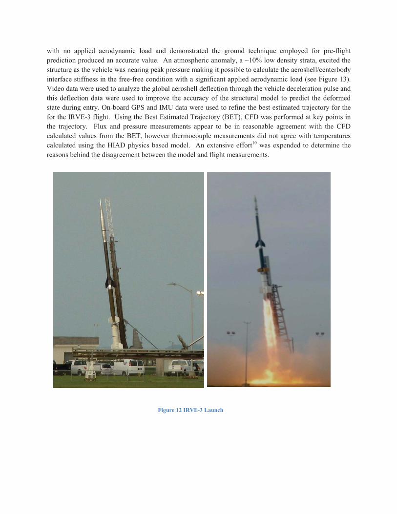
with no applied aerodynamic load and demonstrated the ground technique employed for pre-flight prediction produced an accurate value. An atmospheric anomaly, a ~10% low density strata, excited the structure as the vehicle was nearing peak pressure making it possible to calculate the aeroshell/centerbody interface stiffness in the free-free condition with a significant applied aerodynamic load (see Figure 13). Video data were used to analyze the global aeroshell deflection through the vehicle deceleration pulse and this deflection data were used to improve the accuracy of the structural model to predict the deformed state during entry. On-board GPS and IMU data were used to refine the best estimated trajectory for the for the IRVE-3 flight. Using the Best Estimated Trajectory (BET), CFD was performed at key points in the trajectory. Flux and pressure measurements appear to be in reasonable agreement with the CFD calculated values from the BET, however thermocouple measurements did not agree with temperatures calculated using the HIAD physics based model. An extensive effort10 was expended to determine the reasons behind the disagreement between the model and flight measurements.
Figure 12 IRVE-3 Launch

VIII. BTP/IRVE-4 A flight spare unit of the IRVE-3 centerbody hardware, referred to as Build to Print (BTP), was built
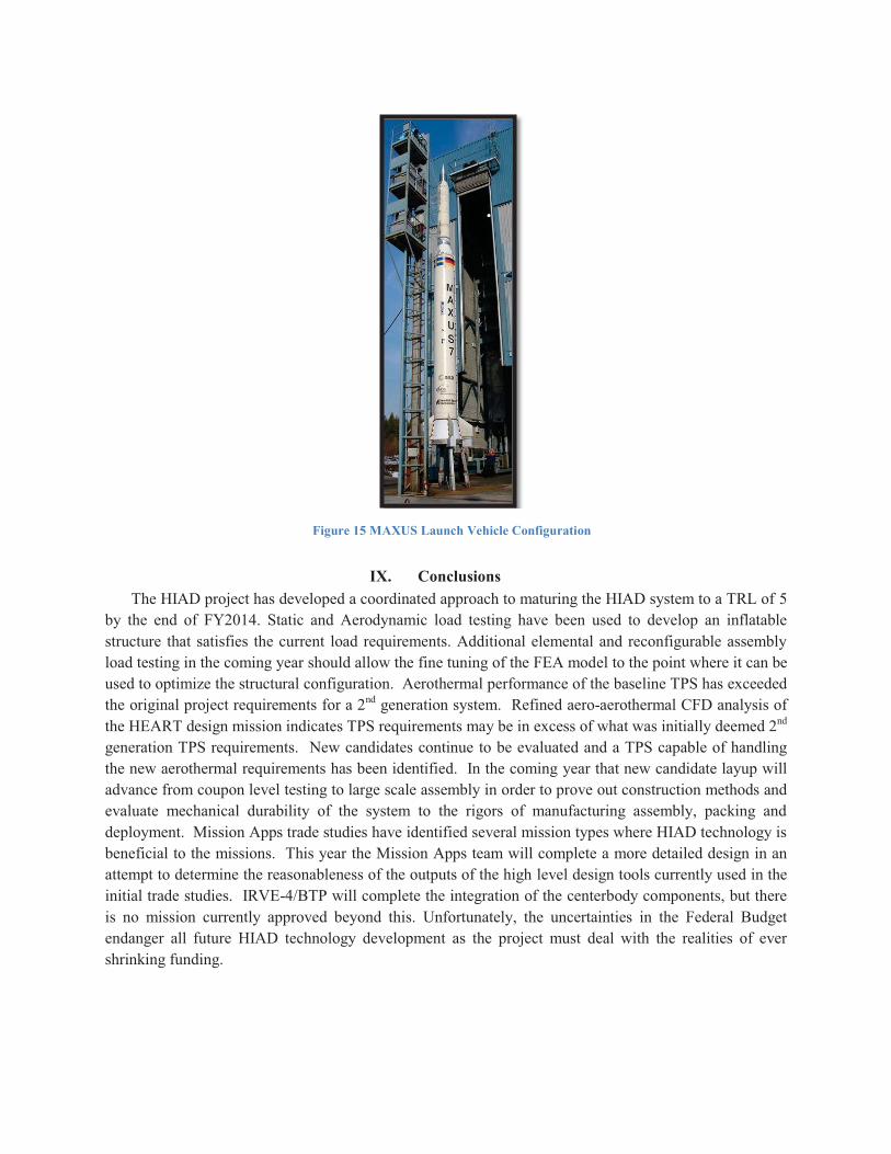
as a risk reduction to have hardware available in the event of a an IRVE-3 launch vehicle failure. With the successful flight of IRVE-3 the BTP unit is now available and is proposed to be used on a new start IRVE-4 mission to OCT. IRVE-3 flight thermocouple data exhibited significantly lower temperatures than were predicted using the environment calculated with the as flown BET and the HIAD developed physics based model. With significant effort, both modelling and aerothermal testing, a plausible explanation for the anomalous readings has been developed, but another flight data set, particularly for a flight with relatively close to the same peak heating rate but a significantly longer pulse, would demonstrate the hypothesis and remove uncertainty. WFF is currently in the process of acquiring 3 Castor IVB motors in an effort to increase the payload capacity of their sounding rocket suite. The Castor IVB has previously been utilized by the Swedish Space Corporation from 1991 through 2006 for the Maxus series of 7 microgravity sub orbital launches. The Maxus configuration (see Figure 15) consisted of a 22” payload shroud atop the Castor IVB, so the BTP hardware could launch with no outer mold line change. Preliminary simulation indicates using Castor IVB the BTP hardware could achieve a peak heating rate similar to IRVE-3 but with roughly twice the IRVE-3 duration (see Figure 14).
Figure 14 IRVE-4 Preliminary Estimation of Environments Achievable in Castor IVB
Data IRVE-3 800 lb 1000 lb3 m 4 m 5 m 3 m 4 m 5 m
30°E
ntry Max Heat Rate (W/cm2) 13.8 14.7 12.1 12.1 13.7 11.2 9.9
Heat Pulse (s) - Time to 0.1 W/cm2 35 59 54 54 59 54 52Total Heat Load (J/cm2) 188 326 258 258 310 245 210Max Deceleration (g) 19.7 12.7 12.7 12.7 12.2 12.2 12.3
40°E
ntry Max Heat Rate (W/cm2) 13.8 17.5 14.3 12.6 16.5 13.5 11.9
Heat Pulse (s) - Time to 0.1 W/cm2 35 47 44 42 48 44 42
Total Heat Load (J/cm2) 188 306 243 208 292 232 199
Max Deceleration (g) 19.7 16.7 16.6 16.7 16.2 16.1 16.1
Figure 13 IRVE-3 Atmospheric Low Density Anomaly
IX. Conclusions The HIAD project has developed a coordinated approach to maturing the HIAD system to a TRL of 5
by the end of FY2014. Static and Aerodynamic load testing have been used to develop an inflatable structure that satisfies the current load requirements. Additional elemental and reconfigurable assembly load testing in the coming year should allow the fine tuning of the FEA model to the point where it can be used to optimize the structural configuration. Aerothermal performance of the baseline TPS has exceeded the original project requirements for a 2nd generation system. Refined aero-aerothermal CFD analysis of the HEART design mission indicates TPS requirements may be in excess of what was initially deemed 2nd generation TPS requirements. New candidates continue to be evaluated and a TPS capable of handling the new aerothermal requirements has been identified. In the coming year that new candidate layup will advance from coupon level testing to large scale assembly in order to prove out construction methods and evaluate mechanical durability of the system to the rigors of manufacturing assembly, packing and deployment. Mission Apps trade studies have identified several mission types where HIAD technology is beneficial to the missions. This year the Mission Apps team will complete a more detailed design in an attempt to determine the reasonableness of the outputs of the high level design tools currently used in the initial trade studies. IRVE-4/BTP will complete the integration of the centerbody components, but there is no mission currently approved beyond this. Unfortunately, the uncertainties in the Federal Budget endanger all future HIAD technology development as the project must deal with the realities of ever shrinking funding.
Figure 15 MAXUS Launch Vehicle Configuration
References 1 Calomino, Anthony, “NASA HIAD Generation 1 Flexible Thermal Protection System Development and Flight
Performance”, 22nd AIAA Aerodynamic Decelerator Systems Conference, Daytona Beach, FL March 25-28, 2013. 2 Cassell, Alan, “Design and Execution of the Hypersonic Inflatable Aerodynamic Decelerator Large-Article Wind Tunnel
Experiment”, 22nd AIAA Aerodynamic Decelerator Systems Conference, Daytona Beach, FL March 25-28, 2013. 3 Swanson, Greg, “Tension Measurements of Hypersonic Inflatable Aerodynamic Decelerator Structural Straps under Static
and Dynamic Loading,” 22nd AIAA Aerodynamic Decelerator Systems Conference, Daytona Beach, FL March 25-28, 2013. 4 Laura Kushner, “Photogrammetry of a Hypersonic Inflatable Aerodynamic Decelerator in the NFAC”, 22nd AIAA
Aerodynamic Decelerator Systems Conference, Daytona Beach, FL March 25-28, 2013.
5 Kazemba, Cole “Determination of the Deformed Structural Shape of HIADs from Photogrammetric Wind Tunnel Data,” 22nd AIAA Aerodynamic Decelerator Systems Conference, Daytona Beach, FL March 25-28, 2013.
6 Bose, David, “The Hypersonic Inflatable Aerodynamic Decelerator (HIAD) Mission Applications Study”, 22nd AIAA Aerodynamic Decelerator Systems Conference, Daytona Beach, FL March 25-28, 2013.
7 Shidner, Jeremy, “HIAD Mission Applications”, IEEE Aerospace Conference, Big Sky, MT, March 2-9, 2013. 8 Aaron Olds, David Bose, “IRVE-3 Post-Flight Reconstruction”, 22nd AIAA Aerodynamic Decelerator Systems
Conference, Daytona Beach, FL March 25-28, 2013. 9 Valerie Gsell, Robert Dillman, “ACS Performance of IRVE-3”, AAS 36th Annual Guidance and Control Conference,
Breckenridge, CO Feb 13, 2013. 10 Bruce III, Walter, “Inflatable Reentry Vehicle Experiment 3 (IRVE-3) Comparison of Flexible TPS Flight and Analytical
Aerothermal Data”, 22nd AIAA Aerodynamic Decelerator Systems Conference, Daytona Beach, FL March 25-28, 2013.
Bibliography 1 Joseph A. Del Corso, Walter E. Bruce, III, Kaitlin A. Liles, and Stephen J. Hughes, “Thermal Analysis and Testing of Candidate Materials for PAIDAE Inflatable Aeroshell,” 21st AIAA Aerodynamic Decelerator Systems Conference, Dublin, Ireland May 23-26, 2011. 2 Stephen A. O’Keefe and David M. Bose, “IRVE-II Post-Flight Trajectory Reconstruction”, AIAA-2010-7515 AIAA Atmospheric Flight Mechanics Conference, Toronto, Ontario, Aug. 2-5, 2010. 3 Robert A. Dillman, Stephen J. Hughes, Richard J. Bodkin, David M. Bose, Joseph Del Corso, and F. McNeil Cheatwood: “Flight Performance of the Inflatable Reentry Vehicle Experiment II”, 7th International Planetary Probe Workshop, Barcelona, Spain, June 14–18, 2010. 4 O’Keefe, S. A., Bose, D. M., “IRVE-II Post-Flight Trajectory Reconstruction,” AIAA Atmospheric Flight Mechanics Conference, AIAA Paper 2010-7515, 200914 O’Keefe, S. A., Bose, D. M., “IRVE-II Post-Flight Trajectory Reconstruction,” AIAA Atmospheric Flight Mechanics Conference, AIAA Paper 2010-7515, 2009 5 Axdahl, E., Cruz, J. R., Schoenenberger, M. and Wilhite, A., “Flight Dynamics of an Aeroshell Using an Attached Inflatable Aerodynamic Decelerator,” AIAA Paper 2009-2963, 2009 6 Del Corso, J.A., Bruce, W.E., Liles, K.A., Hughes, S.J., “Thermal Analysis and Testing of Candidate Materials for PAIDAE Inflatable Aeroshell”, 20th AIAA Aerodynamic Decelerator Systems Conference, May 2009 7 Stephen J. Hughes, Joanne S. Ware, Joseph A. Del Corso, and Rafael A. Lugo “Deployable Aeroshell Flexible Thermal Protection System Testing”, 20th AIAA Aerodynamic Decelerator Systems Conference, May 2009 8 Player, Charles, “PAIDAE Thermal Protection System Testing Final Report – FY2008”, PAI-DAE-3.3-012, NASA Langley Research Center, 2008 9 Bruce III, Walter E., “Aeroassist Inflatable Reentry System (AIRS) Thermal Protection System (TPS) Thermal Analysis”, STSB-2006-002, February 2006 10 Michael C. Lindell, Stephen J. Hughes, Megan Dixon, and Cliff E. Willey, “Structural Analysis and Testing of the Inflatable Re-entry Vehicle Experiment (IRVE)”, AIAA-2006-1699 11 Starr, B. R., Bose, D. M., Thornblom, M., and Kilcoyne, D. "Inflatable Reentry Vehicle Experiment Flight Performance Simulations," 53rd JANNAF Propulsion Meeting, Monterey, CA, Dec. 5-8, 2005. 12 F. McNeil Cheatwood, James M. Corliss, Charles J. Player, Cliff E. Willey, and James Stein: “Inflatable Entry Systems Technologies for NASA Exploration’’, AIAA Paper 2005-6811, Space 2005 Conference, Long Beach, CA, August 30 – September 1, 2005. 13 Charles J. Player, Dr. F. McNeil Cheatwood, James Corliss: “Development of Inflatable Entry Systems Technologies’’, 3rd International Planetary Probe Workshop, Anavyssos, Greece, June 27 – July 1, 2005. 14 R. A. Dillman, F. M. Cheatwood, J. M. Corliss, S. J. Hughes: “Technology Developments for Atmospheric Entry Systems’’, 3rd International Planetary Probe Workshop, Anavyssos, Greece, June 27 - July 1, 2005.

15 Stephen J. Hughes, Robert A. Dillman, Brett R. Starr, Ryan A. Stephan, Michael C. Lindell, Charles J. Player, and F. McNeil Cheatwood: “Inflatable Re-entry Vehicle Experiment (IRVE) Design Overview’’, 18th AIAA Aerodynamic Decelerator Systems Technology Conference and Seminar, Munich, Germany, May 24-26, 2005. 16 Claude A. Graves, Carlos H. Westhelle, Christopher Madsen, Richard W. Powell, F. Neil Cheatwood, Charles J. Player, Juan R. Cruz, Alicia D. Cianciolo, Glen Brown, Chirold Epp: “Inflatable Aeroshells as an Alternative Aerodynamic Decelerator,” AAS Paper 05-062, 28th Annual AAS Guidance and Control Conference, Breckenridge, CO, February 5-9, 2005 17 M.C.A.M. van der List, L.D. van Vilet, H.M Sanders, P. van Put, J.W.E.C. Elst: “Applications for Solid Propellant Cool Gas Generator Technology”. 18 Bradford Engineering, Bradford Datasheet, Solid Propellant Cool Gas Generator – Revision: OCT 2009 19 Airborne Systems 85-1687 “Proposed Baseline Design Supersonic Inflatable Aerodynamic Decelerator (SIAD)”
Acknowledgments The authors would like to acknowledge, in addition to the other authors sited in references, the rest of the outstanding team across the country who, without their efforts, this technology development would not be possible. The list included here is long and yet even still there are likely to be people inadvertently left off the list. LaRC Team Lee Abston, Vincent P. Adams, Ruth M. Amundsen, Charles W. Antill, Katherine Barnstorff, Robert O. Betts, Richard J. Bodkin, Frank L. Boyer, Arthur T. Bradley, Amy Brewer, Timothy Cannella, Ellen B. Carpenter, Daniel J. Carey, Charles E. Cockrell, Michael Edward Coleman, Jim Corliss, David Hart Covington, Larry J. Cowen, Amanda Moore Cutright, Debra Dajon, Kamran Daryabeigi, Jesse M. Davis, John A. Dec, Joseph Anthony Del Corso, Kennedy Delgado, Robert A. Dillman, John M. DiNonno, Ceseley Dunbar, Anjie Lin Emmett, Walter C. Engelund, David Fahringer, Crystal J. Fenn, Todd Ferrante, Michael G. Fleck, Michael A. Flood, Rosemary C. Froehlich, Mark W. Frye, Shawn T. Gallagher, Wayne D. Geouge, David A. Gilman, Guillermo A. Gonzalez, Charlie Greenhalgh, Thomas A. Grepiotis, Marion E. Hales, E. Thomas Hall, Jason Hall, Wade T. Hall, Sean M. Hancock, Stephen F. Harvin, David A. Helton, Jeff A. Herath, George C. Hilton, Brian R. Hollis, Stephen J. Horan, Charles E. Jenkins, R. Keith Johnson, Leslie J. Johnson, Mark L.M Jones, David G. Kessler, Jeffrey R. Knutson, David R. Komar, Ashley M. Korzun, Shawn Krizan, Christopher A. Kuhl, Prasad Kutty, Robert Kyle, Laura A. Leybold, Michael C. Lindell, Justin D. Littell, Christopher Micha Little, Daniel Litton, Jeff Massie, Johnny C. Mau, Ali Reza Mazaheri, David Alan Mclain, Nathaniel J. Mesick, Nathanael A. Miller, Gene S. Monroe, Aaron L. Morris, Lee Noble, Daniel R. Norfolk, Kevin O'Neal, Patricia Y. Oneal, James K. Parkinson, Eric Personne, Carrie Rhoades, Chad E. Rice, Shann Julie Rufer, Jamshid A. Samareh, Brian M. Saulman, Bethany A. Schiller, Mark Schoenenberger, Robert C. Scott, Willis J. Scott, Ray Seals, Paul Siemers Scott C. Splinter, Justin D. Templeton, John E. Theisinger, Steven A. Tobin, Dominic R. Trombetta, Robin D. Tutterow, John W. Van Norman, Nicholas Anthony Vitullo, Carl J. Voglewede, Joseph Paul White, Richard D. Winning, Richard G. Winski, A. J. Wise, Charles J.Wittkopp, Timothy Wood Airborn Systems Team Glen Brown, David Jurewicz, Brian Gilles, Paul Anderson, Mike Quinn, Allen Lowery, Ben Tutt, Christopher Kelley, Leo Lichodziejewski, Jackson Bond Enterprises WFF Team Ernest L. Bowden, James K. Diehl, Keith Foster, Valerie Gsell, James R. Hoffman, Eric C. Johnson, David T. Kilcoyne, David J. Krause, Giovanni Rosanova, Jay Scott, Walter V. Suplick, Eric P. Taylor, John Valliant, Ricky L. Weaver, Libby West, Timothy R. Wilson, ARC Team Jeffrey D. Brown, Cole D Kazemba, Carl E. Kruger, Bernard Laub, Bill Thomas Quach, Marc D. Rezin, NFAC Team Patrick W. Goulding, Stephen Juhyung Lee, and all of the NFAC facility operators DFRC Team Tony Chen, Larry D. Hudson, Matthew R. Moholt, Anthony Piazza GRC Team Eric H. Baker, Frederick W. Dynys, Frances I. Hurwitz, Maryann Meador, Roy M. Sullivan, Stephanie L. Vivod, JSC Team Christopher J. Cerimele, Steven Del Papa, Ronald K. Lewis, Stephen W. Miller, Ronald R. Sostaric, Susan J. Stachowiak, Carlie H. Zumwalt, Boeing LCAT Team Greg Bass, Matthew P. Kardell, John R. Simms


