Hi-lume 1% EcoSystem / 3-Wire L3D Driver...
40
SPECIFICATION SUBMITTAL Page Job Name: Job Number: Model Numbers: LED Dimming Driver Hi-lume 1% EcoSystem / 3-Wire L3D Architectural Dimming 369325k 1 09.29.16 Hi-lume 1% EcoSystem / 3-Wire L3D Driver Overview Hi-lume 1% EcoSystem / 3-Wire Driver is a high-performance LED driver that provides smooth, continuous 1% dimming for virtually any LED fixture, whether it requires constant-current or constant-voltage. It is the most versatile LED driver offered today due to its compatibility with a wide variety of LED arrays, multiple form factors, and numerous control options. Features • Continuous, flicker-free dimming from 100% to 1%. • Compatible with Energi Savr Node unit with EcoSystem, GRAFIK Eye QS control unit, PowPak dimming module with EcoSystem, and Quantum systems, allowing for integration into a planned or existing EcoSystem lighting control solution. Please see Compatible Controls chart or contact Lutron for details regarding compatible controls. • Standard 3-wire, line-voltage phase-control technology for consistent dimming performance and compatibility with all Lutron 3-wire fluorescent controls. • QwikFig compatible. For more information please refer to Lutron P/N 367-2533 (K and M case only). • Line voltage miswire protection on EcoSystem control inputs. • 100% performance tested at factory. • A rated lifetime of 50,000 hours @: – t c = 149 °F (65 °C) for 40 W drivers – t c = 158 °F (70 °C) for 50 W drivers • UL recognized and listed options for United States and Canada. • NOM certified option for Mexico. • Type TL Rated. • FCC Part 15 compliant for commercial applications at 120 V ~ or 277 V ~. • Pulse Width Modulation (PWM) or Constant-Current Reduction (CCR) dimming methods available. See Application Note #360 for details. • RoHS Compliant. • For more information please go to: www.lutron.com/hilume1led Case type K 3.00 in (76 mm) W x 1.00 in (25 mm) H x 4.90 in (124 mm) L Case type M 1.18 in (30 mm) W x 1.00 in (25 mm) H x 14.25 in (362 mm) L The Hi-lume 1% EcoSystem / 3-Wire family of drivers includes models which operate at a maximum power of 40 W or less as well as models which can operate up to 50 W. • 40 W or less models – output ranges A-M and X-Z • 50 W models – output ranges N and W (K-case only) For a description of the output ranges please see following pages. Case type KL K-case mounted on a 4.00 in (102 mm) W x 1.50 in (38 mm) H x 4.00 in (102 mm) L junction box to provide wiring compartment
-
Upload
trankhuong -
Category
Documents
-
view
227 -
download
2
Transcript of Hi-lume 1% EcoSystem / 3-Wire L3D Driver...

SPECIF ICAT ION SUBMITTAL Page
Job Name:
Job Number:
Model Numbers:
LED Dimming Driver Hi-lume 1% EcoSystem / 3-Wire L3D Architectural Dimming
369325k 1 09.29.16
Hi-lume 1% EcoSystem / 3-Wire L3D Driver Overview
Hi-lume 1% EcoSystem / 3-Wire Driver is a
high-performance LED driver that provides smooth,
continuous 1% dimming for virtually any LED fixture,
whether it requires constant-current or constant-voltage.
It is the most versatile LED driver offered today due to its
compatibility with a wide variety of LED arrays, multiple
form factors, and numerous control options.
Features
• Continuous, flicker-free dimming from 100% to 1%.
• Compatible with Energi Savr Node unit with EcoSystem,
GRAFIK Eye QS control unit, PowPak dimming module
with EcoSystem, and Quantum systems, allowing for
integration into a planned or existing EcoSystem lighting
control solution. Please see Compatible Controls
chart or contact Lutron for details regarding compatible
controls.
• Standard 3-wire, line-voltage phase-control technology for
consistent dimming performance and compatibility with all
Lutron 3-wire fluorescent controls.
• QwikFig compatible. For more information please refer to
Lutron P/N 367-2533 (K and M case only).
• Line voltage miswire protection on EcoSystem control
inputs.
• 100% performance tested at factory.
• A rated lifetime of 50,000 hours @:
– tc = 149 °F (65 °C) for 40 W drivers
– tc = 158 °F (70 °C) for 50 W drivers
• UL recognized and listed options for United States and
Canada.
• NOM certified option for Mexico.
• Type TL Rated.
• FCC Part 15 compliant for commercial applications
at 120 V ~ or 277 V ~.
• Pulse Width Modulation (PWM) or Constant-Current
Reduction (CCR) dimming methods available. See
Application Note #360 for details.
• RoHS Compliant.
• For more information please go to:
www.lutron.com/hilume1led
Case type K3.00 in (76 mm) W x 1.00 in (25 mm) H x 4.90 in (124 mm) L
Case type M1.18 in (30 mm) W x 1.00 in (25 mm) H x 14.25 in (362 mm) L
The Hi-lume 1% EcoSystem / 3-Wire family of drivers
includes models which operate at a maximum power
of 40 W or less as well as models which can operate
up to 50 W.
• 40 W or less models – output ranges A-M and X-Z
• 50 W models – output ranges N and W (K-case only)
For a description of the output ranges please see
following pages.
Case type KLK-case mounted on a 4.00 in (102 mm) W x 1.50 in (38 mm) H
x 4.00 in (102 mm) L junction box to provide wiring
compartment
SPECIF ICAT ION SUBMITTAL Page
Job Name:
Job Number:
Model Numbers:
LED Dimming Driver Hi-lume 1% EcoSystem / 3-Wire L3D Architectural Dimming
369325k 2 09.29.16
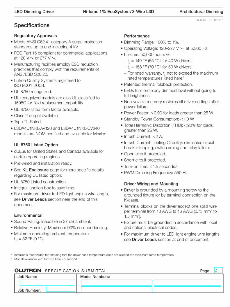
Specifications
Regulatory Approvals• Meets ANSI C62.41 category A surge protection
standards up to and including 4 kV.
• FCC Part 15 compliant for commercial applications
at 120 V ~ or 277 V ~.
• Manufacturing facilities employ ESD reduction
practices that comply with the requirements of
ANSI/ESD S20.20.
• Lutron Quality Systems registered to
ISO 9001.2008.
• UL 8750 recognized.
• UL recognized models are also UL classified to
1598C for field replacement capability
• UL 8750 listed form factor available.
• Class 2 output available.
• Type TL Rated.
• L3DA4U1NKL-AV120 and L3DA4U1NKL-CV240
models are NOM certified and available for Mexico.
UL 8750 Listed Option
• cULus for United States and Canada available for
certain operating regions.
• Pre-wired and installation ready.
• See KL Enclosure page for more specific details
regarding UL listed option.
• UL 8750 Listed construction.
• Integral junction box to save time.
• For maximum driver-to-LED light engine wire length,
see Driver Leads section near the end of this
document.
Environmental• Sound Rating: Inaudible in 27 dB ambient.
• Relative Humidity: Maximum 90% non-condensing.
• Minimum operating ambient temperature
ta = 32 °F (0 °C).
Performance• Dimming Range: 100% to 1%.
• Operating Voltage: 120–277 V ~ at 50/60 Hz.
• Lifetime: 50,000 hours @:
– tc = 149 °F (65 °C)1 for 40 W drivers.
– tc = 158 °F (70 °C)1 for 50 W drivers.
– For rated warranty, tc not to exceed the maximum
rated temperatures listed here.1
• Patented thermal foldback protection.
• LEDs turn on to any dimmed level without going to
full brightness.
• Non-volatile memory restores all driver settings after
power failure.
• Power Factor: > 0.90 for loads greater than 25 W
• Standby Power Consumption: < 1.0 W
• Total Harmonic Distortion (THD): < 20% for loads
greater than 25 W.
• Inrush Current: < 2 A.
• Inrush Current Limiting Circuitry: eliminates circuit
breaker tripping, switch arcing and relay failure.
• Open circuit protected.
• Short circuit protected.
• Turn-on time: ≤ 1.5 seconds.2
• PWM Dimming Frequency: 550 Hz.
Driver Wiring and Mounting• Driver is grounded by a mounting screw to the
grounded fixture (or by terminal connection on the
K-case).
• Terminal blocks on the driver accept one solid wire
per terminal from 18 AWG to 16 AWG (0.75 mm2 to
1.5 mm2).
• Fixture must be grounded in accordance with local
and national electrical codes.
• For maximum driver to LED light engine wire lengths
see Driver Leads section at end of document.
1 Installer is responsible for ensuring that the driver case temperature does not exceed the maximum rated temperature.2 Models available with turn-on time ≤ 1 second.

SPECIF ICAT ION SUBMITTAL Page
Job Name:
Job Number:
Model Numbers:
LED Dimming Driver Hi-lume 1% EcoSystem / 3-Wire L3D Architectural Dimming
369325k 3 09.29.16
How to Build a Model Number: Hi-lume 1% EcoSystem / 3-Wire
L 3 D A _ U 1 _ _ _ - _ _ _ _ _ Example: L3DA4U1UKS-HC070For further assistance selecting your model
number, contact our LED Center of Excellence
at 1.877.346.5338 or [email protected]
Case Size:K = Compact
M = Stick
Current Level (for Constant-Current):020 = 0.20 A; 021 = 0.21 A . . . 070 = 0.70 A . . . 210 = 2.10 A
Voltage Level (for Constant-Voltage):100 = 10.0 V; 105 = 10.5 V . . . 600 = 60.0 V
40 W Drivers
Class 2 Constant-Voltage
A = 10.0 V–12.0 V*
B = 12.5 V–20.0 V **
C = 20.5 V–24.0 V **
D = 24.5 V–38.0 V **
Isolated Non-Class 2
Constant-Voltage
X = 38.5 V–60.0 V **
Class 2 Constant-Current
E = 0.20 A–0.50 A 30 V–54 V
F = 0.51 A–1.00 A 30 V–54 V **
G = 0.20 A–0.70 A 8 V–20 V
H = 0.20 A–0.70 A 15 V–38 V
I = 0.71 A–1.05 A 8 V–20 V
J = 0.71 A–1.05 A 15 V–38 V
K = 1.06 A–1.50 A 8 V–20 V
L = 1.06 A–1.50 A 15 V–38 V **
M = 1.51 A–2.10 A 8 V–19.9 V **
Isolated Non-Class 2
Constant-Current
Y = 0.20 A–0.50 A 30 V–60 V
Z = 0.51 A–1.00 A 30 V–60 V **
50 W Drivers
Class 2 Constant-Current
N = 0.71 A–1.05 A 35 V–54 V* *
Isolated Non-Class 2
Constant-Current
W = 0.71 A–1.05 A 35 V–60 V **
* 3.33 A maximum.
** Output parameter is power-limited for
these output ranges. Consult detailed
specifications on the following pages for
each range.
LED Load Output Range (see the following pages for more detail):
Maximum Power:4 = 40 W
maximum5 = 50 W
maximum (K-case only)
Case Style:S = Studded (K case only)
N = Non-Studded
L = UL Listed (K case only)
Certification:U = UL / cULus Listed
N = NOM Certified
Driver Output:C = Constant-current driver with pulse width
modulation (PWM) dimming
A = Constant-current driver with constant-current
reduction (CCR) dimming
V = Constant-voltage driver with pulse width
modulation (PWM) dimming

SPECIF ICAT ION SUBMITTAL Page
Job Name:
Job Number:
Model Numbers:
LED Dimming Driver Hi-lume 1% EcoSystem / 3-Wire L3D Architectural Dimming
369325k 4 09.29.16
How to Build a Bulk Model Number (For use with Lutron QwikFig technology): Hi-lume 1% EcoSystem / 3-Wire
40 W Drivers
L3DA4U1U _ _ - _ _ BLK
Case Size:
K = Compact
M = Stick
K-case and M-case
1A = Covers “LED Load Output Range” Y and Z
2A = Covers “LED Load Output Range” M
3A = Covers “LED Load Output Range” E and F (CCR dimming only)
K-case only
2G = Covers “LED Load Output Range” G
2H = Covers “LED Load Output Range” H
2R= Covers “LED Load Output Range” I and K
2S= Covers “LED Load Output Range” J and L
M-case only
2B = Covers “LED Load Output Range” H, J, and L
2C = Covers “LED Load Output Range” G, I, and K
Bulk Models:Coverage based on “LED Load Output Range” from standard non-configurable models shown in the How to Build a Model Number section.Example Standard model number: L3DA4U1UKS-HC070 has LED load output range = H
Case Style: 1
S = Studded
(K-case only)
N = Non-Studded
(All M-case models)
50 W Drivers
L3DA5U1UK _ - _ _ BLK
Case Style:
S = Studded
N = Non-Studded 1B = Covers “LED Load Output Range” W
3B = Covers “LED Load Output Range” N (CCR dimming only)
Note: Only the model numbers falling into the structure listed above can be configured with QwikFig. Standard
model numbers configured at Lutron will not be capable of being reconfigured at another facility.1 QwikFig bulk drivers are only available as UL recognized.

SPECIF ICAT ION SUBMITTAL Page
Job Name:
Job Number:
Model Numbers:
LED Dimming Driver Hi-lume 1% EcoSystem / 3-Wire L3D Architectural Dimming
369325k 5 09.29.16
45
Ou
tpu
t P
ow
er (
W)
40
Output Power vs. Output Voltage
0 10 12 20 30 40 50 60
Output Voltage (V)
35
30
25
20
15
10
5
0
“A” Output Range, Voltage Driver Models
A
Voltage Driver Operation Range:
Typical Performance Specifications:
Parameter 120 V~ 240 V~ 277 V~ Test Conditions
Input Current 390 mA 210 mA 170 mA ta = 25 °C,
12.0 V 40 W load,
Maximum Light Output,
K-case
Power Factor 0.99 0.97 0.95
THD 14% 17% 16%
Driver Efficiency 81% 83% 83%
Ou
tpu
t C
urr
ent
(A)
3.5
Output Current vs. Output Voltage
0 10 12 20 30 40 50 60
Output Voltage (V)
3.3
3.0
2.5
2.0
1.5
1.0
0.5
0
A
Effi
cien
cy (%
)
85
Driver Efficiency vs. Output Power at 277 V~
0 10 15 20 25 30 35 40
Output Power (W)
80
75
70
65
60
Effi
cien
cy (%
)
90
Driver Efficiency vs. Output Power at 120 V~
5 10 15 20 25 30 35 40
Output Power (W)
85
80
75
70
65
60
90
5 W Min.
3.3 A Max.
10.0 V 12.0 V
10.0 V12.0 V
Driver Type Output Dimming Method
Output Voltage Output Current
Output Power
Standards Recognition
KL Case Option Standards Recognition for KL Case
Constant-Voltage
Driver (Class 2)
Pulse Width Modulation
(PWM)10.0–12.0 V PWM 0.42–3.3 A 5–40 W Yes

SPECIF ICAT ION SUBMITTAL Page
Job Name:
Job Number:
Model Numbers:
LED Dimming Driver Hi-lume 1% EcoSystem / 3-Wire L3D Architectural Dimming
369325k 6 09.29.16
Effi
cien
cy (%
)
85
Driver Efficiency vs. Output Power at 277 V~
0 10 15 20 25 30 35 40
Output Power (W)
80
75
70
65
60
Effi
cien
cy (%
)
90
Driver Efficiency vs. Output Power at 120 V~
5 10 15 20 25 30 35 40
Output Power (W)
85
80
75
70
65
60
45
Ou
tpu
t P
ow
er (
W)
40
Output Power vs. Output Voltage
0 10 12.5 20 30 40 50 60
Output Voltage (V)
35
30
25
20
15
10
5
0
Ou
tpu
t C
urr
ent
(A)
3.5
Output Current vs. Output Voltage
0 10 12.5 20 30 40 50 60
Output Voltage (V)
3.0
2.5
2.0
1.5
1.0
0.5
0
“B” Output Range, Voltage Driver Models
B
Voltage Driver Operation Range:
Typical Performance Specifications:
Parameter 120 V~ 240 V~ 277 V~ Test Conditions
Input Current 390 mA 200 mA 170 mA ta = 25 °C,
20.0 V 40 W load,
Maximum Light Output,
K-case
Power Factor 0.99 0.98 0.97
THD 10% 8% 9%
Driver Efficiency 85% 86% 87%
B
90
5 W Min.
12.5 V
18.0 V
40 W Max.
20.0 V
12.5 V
18.0 V
20.0 V
Driver Type Output Dimming Method
Output Voltage Output Current
Output Power
Standards Recognition
KL Case Option Standards Recognition for KL Case
Constant-Voltage
Driver (Class 2)
Pulse Width Modulation
(PWM)12.5–20.0 V PWM 0.25–3.2 A 5–40 W Yes

SPECIF ICAT ION SUBMITTAL Page
Job Name:
Job Number:
Model Numbers:
LED Dimming Driver Hi-lume 1% EcoSystem / 3-Wire L3D Architectural Dimming
369325k 7 09.29.16E
ffici
ency
(%)
90
Driver Efficiency vs. Output Power at 120 V~
5 10 15 20 25 30 35 40
Output Power (W)
85
80
75
70
65
60
45
Ou
tpu
t P
ow
er (
W)
40
Output Power vs. Output Voltage
0 10 20.5 24 30 40 50 60
Output Voltage (V)
35
30
25
20
15
10
5
0
Ou
tpu
t C
urr
ent
(A)
3.5
Output Current vs. Output Voltage
0 10 20.5 24 30 40 50 60
Output Voltage (V)
3.0
2.5
2.0
1.5
1.0
0.5
0
“C” Output Range, Voltage Driver Models
C
Voltage Driver Operation Range:
Typical Performance Specifications:
Parameter 120 V~ 240 V~ 277 V~ Test Conditions
Input Current 370 mA 190 mA 170 mA ta = 25 °C,
24.0 V 40 W load,
Maximum Light Output,
K-case
Power Factor 0.99 0.97 0.96
THD 10% 10% 12%
Driver Efficiency 86% 87% 88%
C
Effi
cien
cy (%
)
85
Driver Efficiency vs. Output Power at 277 V~
0 10 15 20 25 30 35 40
Output Power (W)
80
75
70
65
60
90
5 W Min.
20.5 V
40 W Max.
24.0 V
20.5 V
24.0 V
Driver Type Output Dimming Method
Output Voltage Output Current
Output Power
Standards Recognition
KL Case Option Standards Recognition for KL Case
Constant-Voltage
Driver (Class 2)
Pulse Width Modulation
(PWM)20.5–24.0 V PWM 0.21–1.95 A 5–40 W Yes

SPECIF ICAT ION SUBMITTAL Page
Job Name:
Job Number:
Model Numbers:
LED Dimming Driver Hi-lume 1% EcoSystem / 3-Wire L3D Architectural Dimming
369325k 8 09.29.16E
ffici
ency
(%)
90
Driver Efficiency vs. Output Power at 120 V~
5 10 15 20 25 30 35 40
Output Power (W)
85
80
75
70
65
60
Effi
cien
cy (%
)
85
Driver Efficiency vs. Output Power at 277 V~
0 10 15 20 25 30 35 40
Output Power (W)
80
75
70
65
60
90
45
Ou
tpu
t P
ow
er (
W)
40
Output Power vs. Output Voltage
0 10 20 24.5 30 38 40 50 60
Output Voltage (V)
35
30
25
20
15
10
5
0
Ou
tpu
t C
urr
ent
(A)
3.5
Output Current vs. Output Voltage
0 10 20 24.5 30 38 40 50 60
Output Voltage (V)
3.0
2.5
2.0
1.5
1.0
0.5
0
“D” Output Range, Voltage Driver Models
D
Voltage Driver Operation Range:
Typical Performance Specifications:
Parameter 120 V~ 240 V~ 277 V~ Test Conditions
Input Current 370 mA 190 mA 170 mA ta = 25 °C,
38.0 V 40 W load,
Maximum Light Output,
K-case
Power Factor 0.99 0.98 0.98
THD 6% 9% 11%
Driver Efficiency 87% 88% 88%
D
5 W Min.
24.5 V
40 W Max.
36.0 V 38.0 V
24.5 V
36.0 V
38.0 V
Driver Type Output Dimming Method
Output Voltage Output Current
Output Power
Standards Recognition
KL Case Option Standards Recognition for KL Case
Constant-Voltage
Driver (Class 2)
Pulse Width Modulation
(PWM)24.5–38.0 V PWM 0.13–1.63 A 5–40 W Yes

SPECIF ICAT ION SUBMITTAL Page
Job Name:
Job Number:
Model Numbers:
LED Dimming Driver Hi-lume 1% EcoSystem / 3-Wire L3D Architectural Dimming
369325k 9 09.29.16E
ffici
ency
(%)
90
Driver Efficiency vs. Output Power at 120 V~
6 9 12 15 18 21 24 27
Output Power (W)
85
80
75
70
65
60
Effi
cien
cy (%
)
85
Driver Efficiency vs. Output Power at 277 V~
6 9 12 15 18 21 24 27
Output Power (W)
80
75
70
65
60
90
45
Ou
tpu
t P
ow
er (
W)
40
Output Power vs. Output Current
0 0.20 0.35 0.50 0.70 1.05 1.40 1.75 2.10
Output Current (A)
35
30
25
20
15
10
5
0
Ou
tpu
t V
olt
age
(V)
60
Output Voltage vs. Output Current
0 0.20 0.35 0.50 0.70 1.05 1.40 1.75 2.10
Output Current (A)
54
50
30
20
10
0
“E” Output Range, Current Driver Models
E
Current Driver Operation Range:
Typical Performance Specifications:
Parameter 120 V~ 240 V~ 277 V~ Test Conditions
Input Current 260 mA 140 mA 110 mA ta = 25 °C,
0.50 A 27 W load,
Maximum Light Output,
K-case
Power Factor 0.99 0.98 0.96
THD 10% 10% 12%
Driver Efficiency 85% 85% 85%
When using QwikFig technology, these models can be built from the following bulk units: K-case - L3DA4U1UKx-3ABLK *; M-case - L3DA4U1UMN-3ABLK* x = studded (S) or non-studded (N)
E
40
30 V Min.
0.20 A
54 V Max.
0.35 A
0.50 A
0.20 A
0.35 A
0.50 A
Driver Type Output Dimming Method
Output Voltage
Output Current
Output Power
Standards Recognition KL Case Option
Standards Recognition for KL Case
Constant-Current
Driver (Class 2)
Constant-Current
Reduction (CCR)30–54 V- 0.20–0.50 A 6–27 W
Type TL 83 º / 66 ºC - K-case
Type TL 90 º / 72 ºC - M-case
Yes
SPECIF ICAT ION SUBMITTAL Page
Job Name:
Job Number:
Model Numbers:
LED Dimming Driver Hi-lume 1% EcoSystem / 3-Wire L3D Architectural Dimming
369325k 10 09.29.16O
utp
ut
Vo
ltag
e (V
)
60
Output Voltage vs. Output Current
0 0.35 0.51 0.70 1.00 1.40 1.75 2.10
Output Current (A)
54
50
30
20
10
0
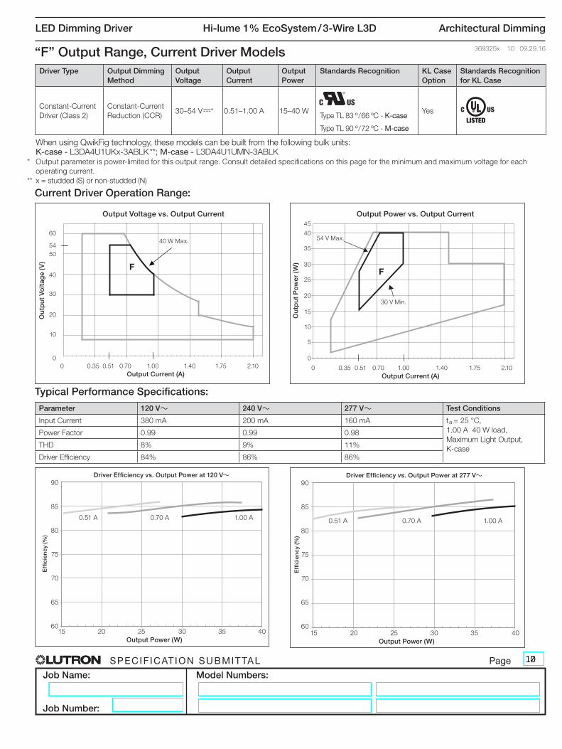
When using QwikFig technology, these models can be built from the following bulk units: K-case - L3DA4U1UKx-3ABLK **; M-case - L3DA4U1UMN-3ABLK* Output parameter is power-limited for this output range. Consult detailed specifications on this page for the minimum and maximum voltage for each
operating current.
** x = studded (S) or non-studded (N)
“F” Output Range, Current Driver Models
F
Current Driver Operation Range:
Typical Performance Specifications:
Parameter 120 V~ 240 V~ 277 V~ Test Conditions
Input Current 380 mA 200 mA 160 mA ta = 25 °C,
1.00 A 40 W load,
Maximum Light Output,
K-case
Power Factor 0.99 0.99 0.98
THD 8% 9% 11%
Driver Efficiency 84% 86% 86%
Effi
cien
cy (%
)
90
85
80
75
70
65
60
Driver Efficiency vs. Output Power at 120 V~
15 20 25 30 35 40
Output Power (W)
0.70 A 1.00 A0.51 A
Effi
cien
cy (%
)
90
85
80
75
70
65
60
Driver Efficiency vs. Output Power at 277 V~
15 20 25 30 35 40
Output Power (W)
0.70 A 1.00 A0.51 A
F
45
Ou
tpu
t P
ow
er (
W)
40
Output Power vs. Output Current
0 0.35 0.51 0.70 1.00 1.40 1.75 2.10
Output Current (A)
35
30
25
20
15
10
5
0
40
30 V Min.
54 V Max.40 W Max.
Driver Type Output Dimming Method
Output Voltage
Output Current
Output Power
Standards Recognition KL Case Option
Standards Recognition for KL Case
Constant-Current
Driver (Class 2)
Constant-Current
Reduction (CCR)30–54 V-* 0.51–1.00 A 15–40 W
Type TL 83 º / 66 ºC - K-case
Type TL 90 º / 72 ºC - M-case
Yes
SPECIF ICAT ION SUBMITTAL Page
Job Name:
Job Number:
Model Numbers:
LED Dimming Driver Hi-lume 1% EcoSystem / 3-Wire L3D Architectural Dimming
369325k 11 09.29.16O
utp
ut
Vo
ltag
e (V
)
60
Output Voltage vs. Output Current
0 0.20 0.35 0.70 1.05 1.40 1.75 2.10
Output Current (A)
8
50
30
20
10
0
40
Ou
tpu
t P
ow
er (
W)
40
Output Power vs. Output Current
0 0.20 0.35 0.70 1.05 1.40 1.75 2.10
Output Current (A)
35
30
25
20
15
10
5
0
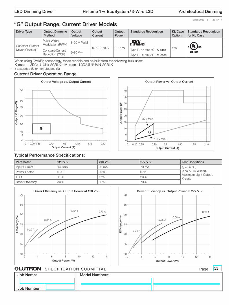
When using QwikFig technology, these models can be built from the following bulk units: K-case - L3DA4U1UKx-2GBLK *; M-case - L3DA4U1UMN-2CBLK* x = studded (S) or non-studded (N)
“G” Output Range, Current Driver Models
G
Current Driver Operation Range:
Typical Performance Specifications:
Parameter 120 V~ 240 V~ 277 V~ Test Conditions
Input Current 140 mA 90 mA 70 mA ta = 25 °C,
0.70 A 14 W load,
Maximum Light Output,
K-case
Power Factor 0.99 0.89 0.85
THD 11% 16% 20%
Driver Efficiency 80% 80% 79%
G
Effi
cien
cy (%
)
90
Driver Efficiency vs. Output Power at 120 V~
2 4 6 8 10 12 14
Output Power (W)
85
80
75
70
65
60
Effi
cien
cy (%
)
85
Driver Efficiency vs. Output Power at 277 V~
2 4 6 8 10 12 14
Output Power (W)
80
75
70
65
60
90
8 V Min.
0.20 A
20 V Max.
0.35 A
0.50 A 0.70 A
0.20 A
0.35 A0.50 A
0.70 A
Driver Type Output Dimming Method
Output Voltage
Output Current
Output Power
Standards Recognition KL Case Option
Standards Recognition for KL Case
Constant-Current
Driver (Class 2)
Pulse Width
Modulation (PWM)8–20 V PWM
0.20–0.70 A 2–14 WType TL 87 º / 55 ºC - K-case
Type TL 89 º / 68 ºC - M-case
YesConstant-Current
Reduction (CCR)8–20 V-
SPECIF ICAT ION SUBMITTAL Page
Job Name:
Job Number:
Model Numbers:
LED Dimming Driver Hi-lume 1% EcoSystem / 3-Wire L3D Architectural Dimming
369325k 12 09.29.16E
ffici
ency
(%)
90
Driver Efficiency vs. Output Power at 120 V~
3 8 13 18 23
Output Power (W)
85
80
75
70
65
60
Ou
tpu
t P
ow
er (
W)
40
Output Power vs. Output Current
0 0.20 0.35 0.70 1.05 1.40 1.75 2.10
Output Current (A)
35
30
25
20
15
10
5
0
Ou
tpu
t V
olt
age
(V)
60
Output Voltage vs. Output Current
0 0.20 0.35 0.70 1.05 1.40 1.75 2.10
Output Current (A)
15
50
30
20
10
0
40
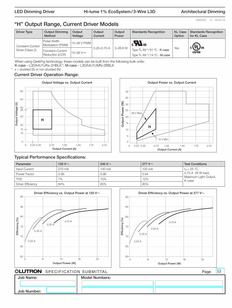
When using QwikFig technology, these models can be built from the following bulk units: K-case - L3DA4U1UKx-2HBLK *; M-case - L3DA4U1UMN-2BBLK* x = studded (S) or non-studded (N)
“H” Output Range, Current Driver Models
H
Current Driver Operation Range:
Typical Performance Specifications:
Parameter 120 V~ 240 V~ 277 V~ Test Conditions
Input Current 270 mA 140 mA 120 mA ta = 25 °C,
0.70 A 26 W load,
Maximum Light Output,
K-case
Power Factor 0.99 0.96 0.94
THD 7% 10% 12%
Driver Efficiency 84% 85% 85%
H
38
Effi
cien
cy (%
)
85
Driver Efficiency vs. Output Power at 277 V~
3 8 13 18 23
Output Power (W)
80
75
70
65
60
90
15 V Min.
0.20 A
38 V Max.
0.35 A
0.50 A
0.70 A
0.20 A
0.35 A
0.50 A
0.70 A
Driver Type Output Dimming Method
Output Voltage
Output Current
Output Power
Standards Recognition KL Case Option
Standards Recognition for KL Case
Constant-Current
Driver (Class 2)
Pulse Width
Modulation (PWM)15–38 V PWM
0.20–0.70 A 3–26.6 WType TL 89 º / 61 ºC - K-case
Type TL 89 º / 74 ºC - M-case
YesConstant-Current
Reduction (CCR)15–38 V-

SPECIF ICAT ION SUBMITTAL Page
Job Name:
Job Number:
Model Numbers:
LED Dimming Driver Hi-lume 1% EcoSystem / 3-Wire L3D Architectural Dimming
369325k 13 09.29.16
Effi
cien
cy (%
)
85
Driver Efficiency vs. Output Power at 277 V~
6 9 12 15 18 21
Output Power (W)
80
75
70
65
60
90
When using QwikFig technology, these models can be built from the following bulk units: K-case - L3DA4U1UKx-2RBLK *; M-case - L3DA4U1UMN-2CBLK* x = studded (S) or non-studded (N)
“I” Output Range, Current Driver Models
I
Current Driver Operation Range:
Typical Performance Specifications:
Parameter 120 V~ 240 V~ 277 V~ Test Conditions
Input Current 210 mA 120 mA 100 mA ta = 25 °C,
1.05 A 21 W load,
Maximum Light Output,
K-case
Power Factor 0.98 0.94 0.92
THD 15% 13% 14%
Driver Efficiency 82% 81% 81%
I
Ou
tpu
t P
ow
er (
W)
40
Output Power vs. Output Current
0 0.20 0.35 0.70 1.05 1.40 1.75 2.10
Output Current (A)
35
30
25
20
15
10
5
0
Ou
tpu
t V
olt
age
(V)
60
Output Voltage vs. Output Current
0 0.35 0.70 1.05 1.40 1.75 2.10
Output Current (A)
8
50
30
20
10
0
40
Effi
cien
cy (%
)
90
Driver Efficiency vs. Output Power at 120 V~
6 9 12 15 18 21
Output Power (W)
85
80
75
70
65
60
8 V Min.
20 V Max.
0.71 A 1.05 A 0.71 A 1.05 A
Driver Type Output Dimming Method
Output Voltage
Output Current
Output Power
Standards Recognition KL Case Option
Standards Recognition for KL Case
Constant-Current
Driver (Class 2)
Pulse Width
Modulation (PWM)8–20 V PWM
0.71–1.05 A 6–21 WType TL 86 º / 63 ºC - K-case
Type TL 89 º / 68 ºC - M-case
YesConstant-Current
Reduction (CCR)8–20 V-

SPECIF ICAT ION SUBMITTAL Page
Job Name:
Job Number:
Model Numbers:
LED Dimming Driver Hi-lume 1% EcoSystem / 3-Wire L3D Architectural Dimming
369325k 14 09.29.16E
ffici
ency
(%)
90
Driver Efficiency vs. Output Power at 120 V~
10 15 20 25 30 35 40
Output Power (W)
85
80
75
70
65
60
When using QwikFig technology, these models can be built from the following bulk units: K-case - L3DA4U1UKx-2SBLK *; M-case - L3DA4U1UMN-2BBLK* x = studded (S) or non-studded (N)
“J” Output Range, Current Driver Models
J
Current Driver Operation Range:
Typical Performance Specifications:
Parameter 120 V~ 240 V~ 277 V~ Test Conditions
Input Current 390 mA 200 mA 170 mA ta = 25 °C,
1.05 A 40 W load,
Maximum Light Output,
K-case
Power Factor 0.99 0.98 0.97
THD 6% 9% 10%
Driver Efficiency 85% 86% 86%
J
Ou
tpu
t P
ow
er (
W)
40
Output Power vs. Output Current
0 0.35 0.70 1.05 1.40 1.75 2.10
Output Current (A)
35
30
25
20
15
10
5
0
Ou
tpu
t V
olt
age
(V)
60
Output Voltage vs. Output Current
0 0.35 0.70 1.05 1.40 1.75 2.10
Output Current (A)
38
50
30
20
10
0
40
15
Effi
cien
cy (%
)
85
Driver Efficiency vs. Output Power at 277 V~
10 15 20 25 30 35 40
Output Power (W)
80
75
70
65
60
90
15 V Min.
38 V Max.
0.71 A 1.05 A 0.71 A 1.05 A
Driver Type Output Dimming Method
Output Voltage
Output Current
Output Power
Standards Recognition KL Case Option
Standards Recognition for KL Case
Constant-Current
Driver (Class 2)
Pulse Width
Modulation (PWM)15–38 V PWM
0.71–1.05 A 11–40 WType TL 86 º / 69 ºC - K-case
Type TL 89 º / 74 ºC - M-case
YesConstant-Current
Reduction (CCR)15–38 V-

SPECIF ICAT ION SUBMITTAL Page
Job Name:
Job Number:
Model Numbers:
LED Dimming Driver Hi-lume 1% EcoSystem / 3-Wire L3D Architectural Dimming
369325k 15 09.29.16
Effi
cien
cy (%
)
85
Driver Efficiency vs. Output Power at 277 V~
9 11 13 15 17 19 21 23 25 27 29
Output Power (W)
80
75
70
65
60
90
When using QwikFig technology, these models can be built from the following bulk units: K-case - L3DA4U1UKx-2RBLK *; M-case - L3DA4U1UMN-2CBLK* x = studded (S) or non-studded (N)
“K” Output Range, Current Driver Models
K
Current Driver Operation Range:
Typical Performance Specifications:
Parameter 120 V~ 240 V~ 277 V~ Test Conditions
Input Current 310 mA 160 mA 130 mA ta = 25 °C,
1.50 A 30 W load,
Maximum Light Output,
K-case
Power Factor 0.99 0.96 0.94
THD 15% 17% 15%
Driver Efficiency 81% 83% 82%
KO
utp
ut
Po
wer
(W
)
40
Output Power vs. Output Current
0 0.35 0.70 1.05 1.40 1.50 1.75 2.10
Output Current (A)
35
30
25
20
15
10
5
0
Ou
tpu
t V
olt
age
(V)
60
Output Voltage vs. Output Current
0 0.35 0.70 1.05 1.40 1.50 1.75 2.10
Output Current (A)
8
50
30
20
10
0
40
Effi
cien
cy (%
)
90
Driver Efficiency vs. Output Power at 120 V~
9 11 13 15 17 19 21 23 25 27 29
Output Power (W)
85
80
75
70
65
60
8 V Min.
20 V Max.
1.20 A1.06 A 1.20 A1.06 A1.50 A 1.50 A
Driver Type Output Dimming Method
Output Voltage
Output Current
Output Power
Standards Recognition KL Case Option
Standards Recognition for KL Case
Constant-Current
Driver (Class 2)
Pulse Width
Modulation (PWM)8–20 V PWM
1.06–1.50 A 9–30 WType TL 86 º / 63 ºC - K-case
Type TL 89 º / 68 ºC - M-case
YesConstant-Current
Reduction (CCR)8–20 V-

SPECIF ICAT ION SUBMITTAL Page
Job Name:
Job Number:
Model Numbers:
LED Dimming Driver Hi-lume 1% EcoSystem / 3-Wire L3D Architectural Dimming
369325k 16 09.29.16E
ffici
ency
(%)
90
Driver Efficiency vs. Output Power at 120 V~
16 19 22 25 28 31 34 37 40
Output Power (W)
85
80
75
70
65
60
Effi
cien
cy (%
)
85
Driver Efficiency vs. Output Power at 277 V~
16 19 22 25 28 31 34 37 40
Output Power (W)
80
75
70
65
60
90
Ou
tpu
t P
ow
er (
W)
40
Output Power vs. Output Current
0 0.35 0.70 1.05 1.40 1.50 1.75 2.10
Output Current (A)
35
30
25
20
15
10
5
0
Ou
tpu
t V
olt
age
(V)
60
Output Voltage vs. Output Current
0 0.35 0.70 1.06 1.40 1.50 1.75 2.10
Output Current (A)
15
50
30
20
10
0
40
When using QwikFig technology, these models can be built from the following bulk units: K-case - L3DA4U1UKx-2SBLK* *; M-case - L3DA4U1UMN-2BBLK* Output parameter is power-limited for this output range. Consult detailed specifications on this page for the minimum and maximum voltage for each
operating current.
** x = studded (S) or non-studded (N)
“L” Output Range, Current Driver Models
L
Current Driver Operation Range:
Typical Performance Specifications:
Parameter 120 V~ 240 V~ 277 V~ Test Conditions
Input Current 390 mA 200 mA 180 mA ta = 25 °C,
1.50 A 40 W load,
Maximum Light Output,
K-case
Power Factor 0.99 0.97 0.96
THD 9% 13% 12%
Driver Efficiency 83% 85% 85%
L
15 V Min.
40 W Max.
1.20 A1.06 A
1.20 A1.06 A
1.50 A1.50 A
Driver Type Output Dimming Method
Output Voltage
Output Current
Output Power
Standards Recognition KL Case Option
Standards Recognition for KL Case
Constant-Current
Driver (Class 2)
Pulse Width
Modulation (PWM)15–38 V PWM
1.06–1.50 A 16–40 WType TL 86 º / 69 ºC - K-case
Type TL 89 º / 74 ºC - M-case
YesConstant-Current
Reduction (CCR)15–38 V-*
SPECIF ICAT ION SUBMITTAL Page
Job Name:
Job Number:
Model Numbers:
LED Dimming Driver Hi-lume 1% EcoSystem / 3-Wire L3D Architectural Dimming
369325k 17 09.29.16E
ffici
ency
(%)
90
Driver Efficiency vs. Output Power at 120 V~
12 14 16 18 20 22 24 26 28 30
Output Power (W)
85
80
75
70
65
60
Effi
cien
cy (%
)
85
Driver Efficiency vs. Output Power at 277 V~
12 14 16 18 20 22 24 26 28 30
Output Power (W)
80
75
70
65
60
90
Ou
tpu
t P
ow
er (
W)
40
Output Power vs. Output Current
0 0.35 0.70 1.05 1.40 1.51 1.75 2.10
Output Current (A)
35
30
25
20
15
10
5
0
Ou
tpu
t V
olt
age
(V)
60
Output Voltage vs. Output Current
0 0.35 0.70 1.06 1.40 1.51 1.75 2.10
Output Current (A)
8
50
30
20
10
0
40
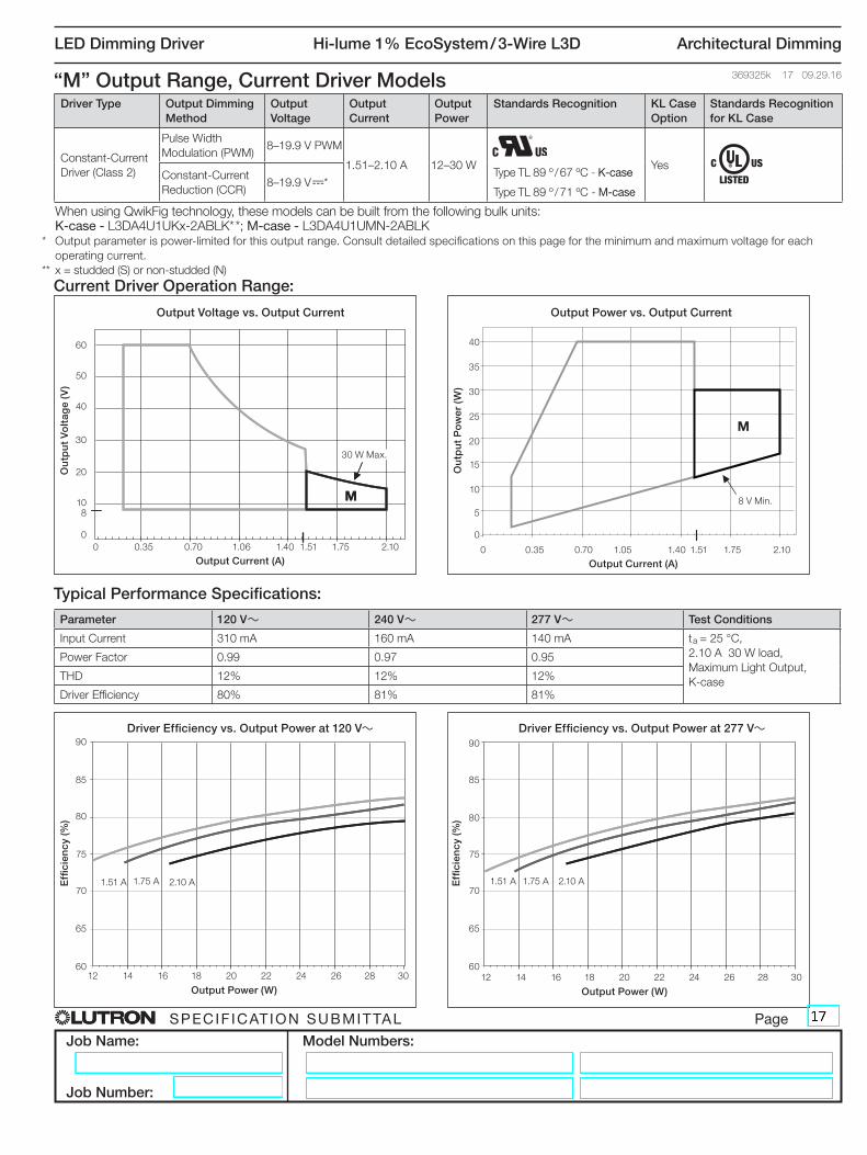
M
When using QwikFig technology, these models can be built from the following bulk units: K-case - L3DA4U1UKx-2ABLK* *; M-case - L3DA4U1UMN-2ABLK* Output parameter is power-limited for this output range. Consult detailed specifications on this page for the minimum and maximum voltage for each
operating current.
** x = studded (S) or non-studded (N)
“M” Output Range, Current Driver Models
M
Current Driver Operation Range:
Typical Performance Specifications:
Parameter 120 V~ 240 V~ 277 V~ Test Conditions
Input Current 310 mA 160 mA 140 mA ta = 25 °C,
2.10 A 30 W load,
Maximum Light Output,
K-case
Power Factor 0.99 0.97 0.95
THD 12% 12% 12%
Driver Efficiency 80% 81% 81%
M
8 V Min.
30 W Max.
1.75 A1.51 A 1.75 A1.51 A2.10 A 2.10 A
Driver Type Output Dimming Method
Output Voltage
Output Current
Output Power
Standards Recognition KL Case Option
Standards Recognition for KL Case
Constant-Current
Driver (Class 2)
Pulse Width
Modulation (PWM)8–19.9 V PWM
1.51–2.10 A 12–30 WType TL 89 º / 67 ºC - K-case
Type TL 89 º / 71 ºC - M-case
YesConstant-Current
Reduction (CCR)8–19.9 V-*

SPECIF ICAT ION SUBMITTAL Page
Job Name:
Job Number:
Model Numbers:
LED Dimming Driver Hi-lume 1% EcoSystem / 3-Wire L3D Architectural Dimming
369325k 18 09.29.16E
ffici
ency
(%)
90
Driver Efficiency vs. Output Power at 120 V~
25 30 35 40 45 50
Output Power (W)
85
80
75
70
65
60
“N” Output Range, Current Driver Models
N
Current Driver Operation Range:
Typical Performance Specifications:
Parameter 120 V~ 240 V~ 277 V~ Test Conditions
Input Current 510 mA 255 mA 220 mA ta = 25 °C,
1.05 A 53 W load,
Maximum Light Output,
K-case
Power Factor 1.00 0.99 0.99
THD 12% 10% 10%
Driver Efficiency 83% 84% 85%
When using QwikFig technology, these models can be built from the following bulk unit: K-case - L3DA5U1UKx-3BBLK *** Output parameter is power-limited for this output range. Consult detailed specifications on this page for the minimum and maximum voltage for each
operating current.
** x = studded (S) or non-studded (N)
N
Ou
tpu
t V
olt
age
(V)
60
Output Voltage vs. Output Current
0 0.35 0.70 1.06 1.40 1.50 1.75 2.10
Output Current (A)
15
50
30
20
10
0
40
Ou
tpu
t P
ow
er (
W)
60
Output Power vs. Output Current
0 0.35 0.70 1.05 1.40 1.50 1.75 2.10
Output Current (A)
55
50
45
40
35
30
25
0
20
15
10
5
Effi
cien
cy (%
)
85
Driver Efficiency vs. Output Power at 277 V~
25 30 35 40 45 50
Output Power (W)
80
75
70
65
60
90
35 V Min.
53 W Max.
0.98 A
0.71 A
0.98 A
0.71 A1.05 A
1.05 A
54 V
53 W Max.
Driver Type Output Dimming Method Output Voltage
Output Current
Output Power
Standards Recognition KL Case Option
Constant-Current Driver
(Class 2)
Constant-Current Reduction
(CCR)35–54 V-* 0.71–1.05 A 25–53 W No
Type TL 87 º / 71 ºC - K-case

SPECIF ICAT ION SUBMITTAL Page
Job Name:
Job Number:
Model Numbers:
LED Dimming Driver Hi-lume 1% EcoSystem / 3-Wire L3D Architectural Dimming
369325k 19 09.29.16
Effi
cien
cy (%
)
85
Driver Efficiency vs. Output Power at 277 V~
25 30 35 40 45 50 53
Output Power (W)
80
75
70
65
60
90
“W” Output Range, Current Driver Models
W
Current Driver Operation Range:
Typical Performance Specifications:
Parameter 120 V~ 240 V~ 277 V~ Test Conditions
Input Current 510 mA 255 mA 220 mA ta = 25 °C,
1.05 A 53 W load,
Maximum Light Output,
K-case
Power Factor 1.00 0.99 0.99
THD 12% 10% 10%
Driver Efficiency 83% 84% 85%
When using QwikFig technology, these models can be built from the following bulk unit: K-case - L3DA5U1UKx-1BBLK *** Output parameter is power-limited for this output range. Consult detailed specifications on this page for the minimum and maximum voltage for each
operating current.
** x = studded (S) or non-studded (N)
W
Ou
tpu
t V
olt
age
(V)
60
Output Voltage vs. Output Current
0 0.35 0.70 1.06 1.40 1.50 1.75 2.10
Output Current (A)
15
50
30
20
10
0
40
Ou
tpu
t P
ow
er (
W)
60
Output Power vs. Output Current
0 0.35 0.70 1.06 1.40 1.50 1.75 2.10
Output Current (A)
55
50
45
40
35
30
25
0
20
15
10
5
Effi
cien
cy (%
)
90
Driver Efficiency vs. Output Power at 120 V~
25 30 35 40 45 50 53
Output Power (W)
85
80
75
70
65
60
35 V Min.
53 W Max.
0.88 A0.71 A 0.88 A0.71 A1.05 A
1.05 A
60 V
53 W Max.
Driver Type Output Dimming Method Output Voltage
Output Current
Output Power
Standards Recognition KL Case Option
Constant-Current Driver
(Isolated, Non-Class 2)
Pulse Width Modulation
(PWM)35–60 V PWM*
0.71–1.05 A 25–53 W NoConstant-Current Reduction
(CCR)35–60 V-*
Type TL 85 º / 71 ºC - K-case

SPECIF ICAT ION SUBMITTAL Page
Job Name:
Job Number:
Model Numbers:
LED Dimming Driver Hi-lume 1% EcoSystem / 3-Wire L3D Architectural Dimming
369325k 20 09.29.16E
ffici
ency
(%)
90
Driver Efficiency vs. Output Power at 120 V~
5 10 15 20 25 30 35 40
Output Power (W)
85
80
75
70
65
60
“X” Output Range, Voltage Driver Models
X
Voltage Driver Operation Range:
Typical Performance Specifications:
Parameter 120 V~ 240 V~ 277 V~ Test Conditions
Input Current 380 mA 190 mA 170 mA ta = 25 °C,
60.0 V 40 W load,
Maximum Light Output,
K-case
Power Factor 0.99 0.99 0.98
THD 7% 6% 8%
Driver Efficiency 88% 89% 89%
X
Ou
tpu
t C
urr
ent
(A)
3.5
Output Current vs. Output Voltage
0 10 20 30 38.5 40 50 60
Output Voltage (V)
1.0
3.0
2.0
1.5
0.5
0
2.5
Ou
tpu
t P
ow
er (
W)
Output Power vs. Output Voltage
0 10 20 30 38.5 40 50 60
Output Voltage (V)
40
35
30
25
20
0
15
10
5E
ffici
ency
(%)
85
Driver Efficiency vs. Output Power at 277 V~
5 10 15 20 25 30 35 40
Output Power (W)
80
75
70
65
60
90
40 W Max.
48.0 V
38.5 V
60.0 V
38.5 V
60.0 V
48.0 V
5 W Min.
Driver Type Output Dimming Method Output Voltage Output Current
Output Power
Standards Recognition
KL Case Option
Constant-Voltage Driver
(Isolated, Non-Class 2)
Pulse Width Modulation
(PWM)38.5 – 60.0 V PWM 0.08–1.04 A 5–40 W No
SPECIF ICAT ION SUBMITTAL Page
Job Name:
Job Number:
Model Numbers:
LED Dimming Driver Hi-lume 1% EcoSystem / 3-Wire L3D Architectural Dimming
369325k 21 09.29.16
Effi
cien
cy (%
)
85
Driver Efficiency vs. Output Power at 277 V~
6 9 12 15 18 21 24 27 30
Output Power (W)
80
75
70
65
60
90
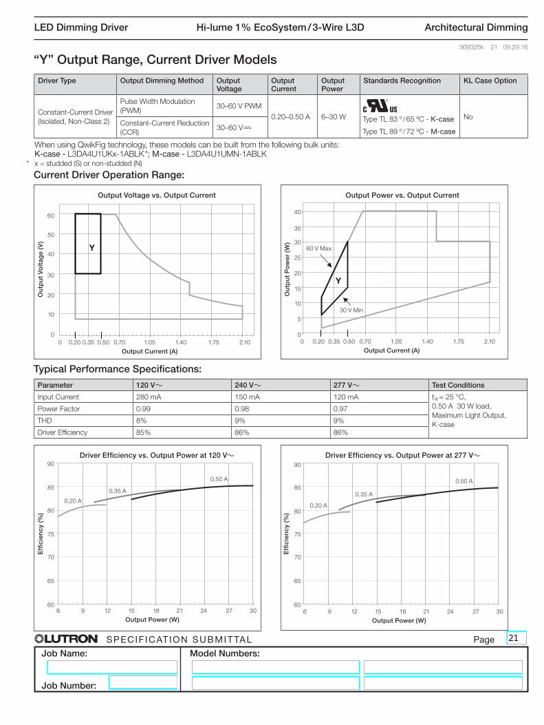
When using QwikFig technology, these models can be built from the following bulk units: K-case - L3DA4U1UKx-1ABLK *; M-case - L3DA4U1UMN-1ABLK* x = studded (S) or non-studded (N)
“Y” Output Range, Current Driver Models
Y
Current Driver Operation Range:
Typical Performance Specifications:
Parameter 120 V~ 240 V~ 277 V~ Test Conditions
Input Current 280 mA 150 mA 120 mA ta = 25 °C,
0.50 A 30 W load,
Maximum Light Output,
K-case
Power Factor 0.99 0.98 0.97
THD 8% 9% 9%
Driver Efficiency 85% 86% 86%
YO
utp
ut
Po
wer
(W
)
Output Power vs. Output Current
0 0.20 0.35 0.50 0.70 1.05 1.40 1.75 2.10
Output Current (A)
40
35
30
25
20
0
15
10
5
Ou
tpu
t V
olt
age
(V)
60
Output Voltage vs. Output Current
0 0.20 0.35 0.50 0.70 1.05 1.40 1.75 2.10
Output Current (A)
50
30
20
10
0
40
Effi
cien
cy (%
)
90
Driver Efficiency vs. Output Power at 120 V~
6 9 12 15 18 21 24 27 30
Output Power (W)
85
80
75
70
65
60
60 V Max.
0.35 A
0.20 A
0.50 A
0.20 A
0.50 A
0.35 A
30 V Min.
Driver Type Output Dimming Method Output Voltage
Output Current
Output Power
Standards Recognition KL Case Option
Constant-Current Driver
(Isolated, Non-Class 2)
Pulse Width Modulation
(PWM)30–60 V PWM
0.20–0.50 A 6–30 W NoConstant-Current Reduction
(CCR)30–60 V-
Type TL 83 º / 65 ºC - K-case
Type TL 89 º / 72 ºC - M-case
SPECIF ICAT ION SUBMITTAL Page
Job Name:
Job Number:
Model Numbers:
LED Dimming Driver Hi-lume 1% EcoSystem / 3-Wire L3D Architectural Dimming
369325k 22 09.29.16
Effi
cien
cy (%
)
85
Driver Efficiency vs. Output Power at 277 V~
6 9 12 15 18 21
Output Power (W)
80
75
70
65
60
90
Ou
tpu
t P
ow
er (
W)
Output Power vs. Output Current
0 0.35 0.51 0.70 1.00 1.40 1.75 2.10
Output Current (A)
40
35
30
25
20
0
15
10
5
Ou
tpu
t V
olt
age
(V)
60
Output Voltage vs. Output Current
0 0.35 0.51 0.70 1.00 1.40 1.75 2.10
Output Current (A)
50
30
20
10
0
40
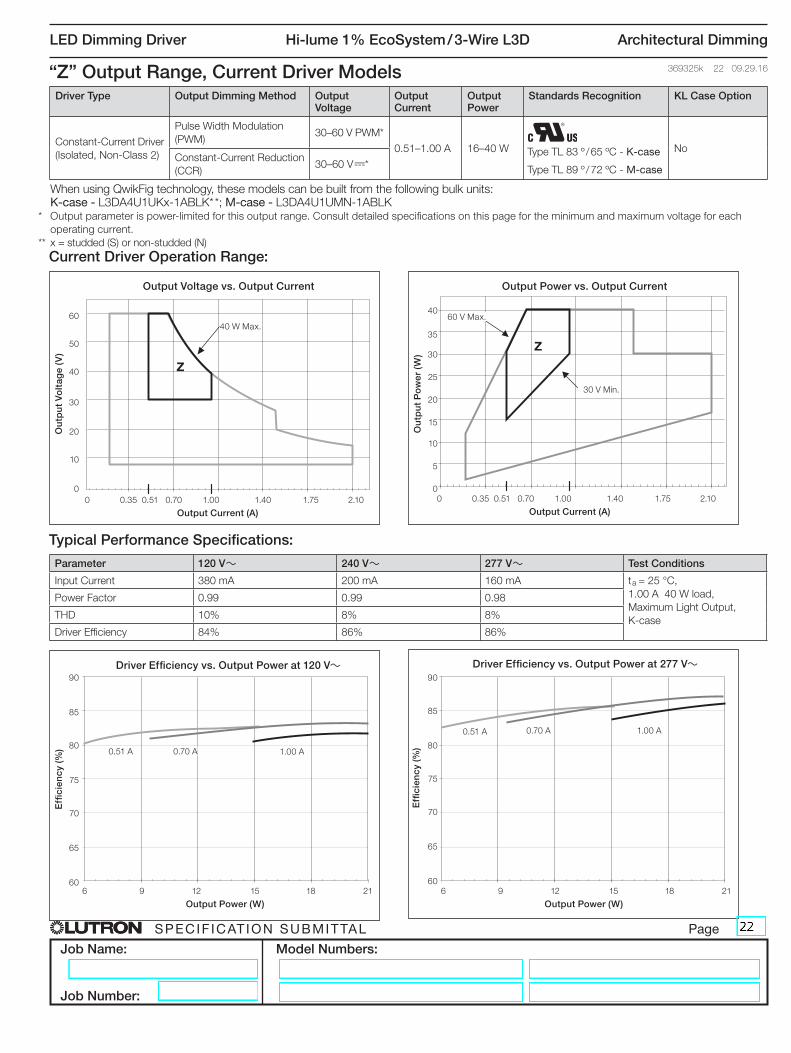
When using QwikFig technology, these models can be built from the following bulk units: K-case - L3DA4U1UKx-1ABLK* *; M-case - L3DA4U1UMN-1ABLK* Output parameter is power-limited for this output range. Consult detailed specifications on this page for the minimum and maximum voltage for each
operating current.
** x = studded (S) or non-studded (N)
“Z” Output Range, Current Driver Models
Z
Current Driver Operation Range:
Typical Performance Specifications:
Parameter 120 V~ 240 V~ 277 V~ Test Conditions
Input Current 380 mA 200 mA 160 mA ta = 25 °C,
1.00 A 40 W load,
Maximum Light Output,
K-case
Power Factor 0.99 0.99 0.98
THD 10% 8% 8%
Driver Efficiency 84% 86% 86%
Z
Effi
cien
cy (%
)
90
Driver Efficiency vs. Output Power at 120 V~
6 9 12 15 18 21
Output Power (W)
85
80
75
70
65
60
60 V Max.
0.70 A0.51 A
1.00 A0.51 A
1.00 A
0.70 A
30 V Min.
40 W Max.
Driver Type Output Dimming Method Output Voltage
Output Current
Output Power
Standards Recognition KL Case Option
Constant-Current Driver
(Isolated, Non-Class 2)
Pulse Width Modulation
(PWM)30–60 V PWM*
0.51–1.00 A 16–40 W NoConstant-Current Reduction
(CCR)30–60 V-*
Type TL 83 º / 65 ºC - K-case
Type TL 89 º / 72 ºC - M-case

SPECIF ICAT ION SUBMITTAL Page
Job Name:
Job Number:
Model Numbers:
LED Dimming Driver Hi-lume 1% EcoSystem / 3-Wire L3D Architectural Dimming
369325k 23 09.29.16
Bulk Model Driver Type Output Dimming Method Output Voltage Output Current Output Power Standards Recognition
3ABLKConstant-Current Driver
(Class 2)
Constant-Current Reduction
(CCR) 30–54 V- 0.20–1.00 A 6–40 W
Type TL 83 º / 66 ºC
Bulk Model Coverage - K-Case Model NumbersFor use with Lutron QwikFig technology
3ABLK Operation Range:
E
F
Ou
tpu
t P
ow
er (
W)
45
LED Load Output Range: Constant-Current Drivers E and F
0 0.20 0.35 0.50 0.70 1.00 1.05 1.40 1.75 2.10
Output Current (A)
40
35
30
25
20
15
10
5
0
3A = Covers “LED Load
Output Range” E and F
(CCR dimming only)54 V
Maximum
30 V
Minimum
SPECIF ICAT ION SUBMITTAL Page
Job Name:
Job Number:
Model Numbers:
LED Dimming Driver Hi-lume 1% EcoSystem / 3-Wire L3D Architectural Dimming
369325k 24 09.29.16
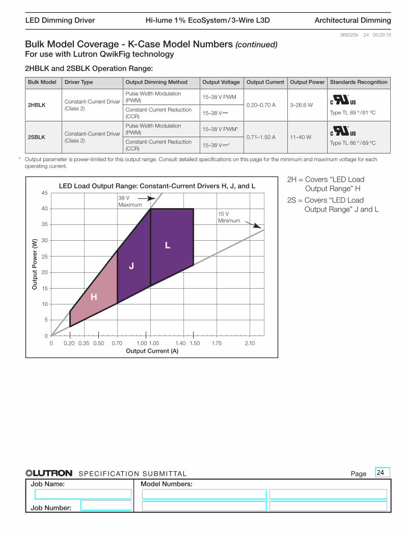
Bulk Model Coverage - K-Case Model Numbers (continued)For use with Lutron QwikFig technology
H
J
L
2HBLK and 2SBLK Operation Range:
Ou
tpu
t P
ow
er (
W)
45
LED Load Output Range: Constant-Current Drivers H, J, and L
40
35
30
25
20
15
10
5
0
Bulk Model Driver Type Output Dimming Method Output Voltage Output Current Output Power Standards Recognition
2HBLKConstant-Current Driver
(Class 2)
Pulse Width Modulation
(PWM)15–38 V PWM
0.20–0.70 A 3–26.6 W
Type TL 89 º / 61 ºC Constant-Current Reduction
(CCR) 15–38 V-
2SBLKConstant-Current Driver
(Class 2)
Pulse Width Modulation
(PWM)15–38 V PWM*
0.71–1.50 A 11–40 WType TL 86 º / 69 ºC Constant-Current Reduction
(CCR) 15–38 V-*
2H = Covers “LED Load
Output Range” H
2S = Covers “LED Load
Output Range” J and L
38 V
Maximum
15 V
Minimum
0 0.20 0.35 0.50 0.70 1.00 1.05 1.40 1.50 1.75 2.10
Output Current (A)
* Output parameter is power-limited for this output range. Consult detailed specifications on this page for the minimum and maximum voltage for each
operating current.

SPECIF ICAT ION SUBMITTAL Page
Job Name:
Job Number:
Model Numbers:
LED Dimming Driver Hi-lume 1% EcoSystem / 3-Wire L3D Architectural Dimming
369325k 25 09.29.16
Bulk Model Coverage - K-Case Model Numbers (continued)For use with Lutron QwikFig technology
2GBLK, 2RBLK, and 2ABLK Operation Range:
G
I
K
M
Ou
tpu
t P
ow
er (
W)
45
LED Load Output Range: Constant-Current Drivers G, I, K, and M
0 0.20 0.35 0.50 0.70 1.00 1.05 1.40 1.50 1.75 2.10
Output Current (A)
40
35
30
25
20
15
10
5
0
Bulk Model Driver Type Output Dimming Method Output Voltage Output Current Output Power Standards Recognition
2GBLKConstant-Current Driver
(Class 2)
Pulse Width Modulation
(PWM)8–20 V PWM
0.20–0.70 A 2–14 W
Type TL 87 º / 55 ºC Constant-Current Reduction
(CCR) 8–20 V-
2RBLKConstant-Current Driver
(Class 2)
Pulse Width Modulation
(PWM)8–20 V PWM
0.71–1.50 A 6–30 WType TL 86 º / 63 ºC Constant-Current Reduction
(CCR) 8–20 V-
2ABLKConstant-Current Driver
(Class 2)
Pulse Width Modulation
(PWM)8–19.9 V PWM*
1.51–2.10 A 12–30 W
Type TL 89 º / 67 ºC Constant-Current Reduction
(CCR) 8–19.9 V-*
2G = Covers “LED Load
Output Range” G
2R = Covers “LED Load
Output Range” I and K
2A = Covers “LED Load
Output Range” M
20 V
Maximum
8 V
Minimum
* Output parameter is power-limited for this output range. Consult detailed specifications on this page for the minimum and maximum voltage for each
operating current.

SPECIF ICAT ION SUBMITTAL Page
Job Name:
Job Number:
Model Numbers:
LED Dimming Driver Hi-lume 1% EcoSystem / 3-Wire L3D Architectural Dimming
369325k 26 09.29.16
1ABLK Operation Range:
Bulk Model Coverage - K-Case Model Numbers (continued)For use with Lutron QwikFig technology
YK
M
Z
Ou
tpu
t P
ow
er (
W)
45
LED Load Output Range: Constant-Current Drivers Y and Z
0 0.20 0.35 0.50 0.70 1.00 1.05 1.40 1.50 1.75 2.10
Output Current (A)
40
35
30
25
20
15
10
5
0
Bulk Model Driver Type Output Dimming Method Output Voltage Output Current Output Power Standards Recognition
1ABLKConstant-Current Driver
(Isolated, Non-Class 2)
Pulse Width Modulation
(PWM)30–60 V PWM*
0.20–1.00 A 6–40 W
Type TL 83 º / 65 ºC Constant-Current Reduction
(CCR) 30–60 V-*
1A = Covers “LED Load
Output Range” Y and Z
60 V
Maximum
30 V
Minimum
* Output parameter is power-limited for this output range. Consult detailed specifications on this page for the minimum and maximum voltage for each
operating current.

SPECIF ICAT ION SUBMITTAL Page
Job Name:
Job Number:
Model Numbers:
LED Dimming Driver Hi-lume 1% EcoSystem / 3-Wire L3D Architectural Dimming
369325k 27 09.29.16
Bulk Model Coverage - K-Case Model Numbers (continued)For use with Lutron QwikFig technology
3BBLK Operation Range:
Bulk Model Driver Type Output Dimming Method Output Voltage Output Current Output Power Standards Recognition
3BBLKConstant-Current Driver
(Class 2)
Constant-Current Reduction
(CCR) 35–54 V-* 0.71–1.05 A 25 –53 W
Type TL 87 º / 71 ºC
I
K
M
N
Ou
tpu
t P
ow
er (
W)
60
LED Load Output Range: Constant-Current Driver N
0 0.35 0.70 1.05 1.40 1.50 1.75 2.10
Output Current (A)
55
50
45
40
35
30
15
5
0
25
20
10
3B = Covers “LED Load
Output Range” N
54 V
Maximum
35 V
Minimum
53 W
Maximum
* Output parameter is power-limited for this output range. Consult detailed specifications on this page for the minimum and maximum voltage for each
operating current.
SPECIF ICAT ION SUBMITTAL Page
Job Name:
Job Number:
Model Numbers:
LED Dimming Driver Hi-lume 1% EcoSystem / 3-Wire L3D Architectural Dimming
369325k 28 09.29.16
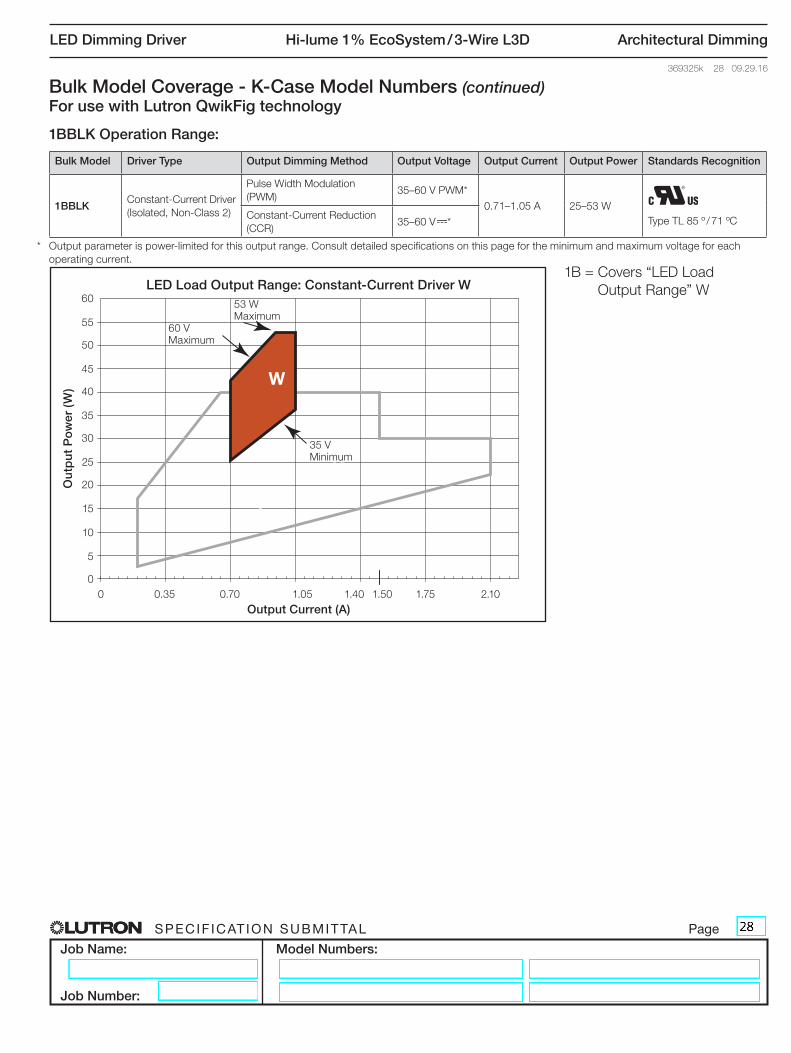
1BBLK Operation Range:
I
K
M
W
Ou
tpu
t P
ow
er (
W)
LED Load Output Range: Constant-Current Driver W
0 0.35 0.70 1.05 1.40 1.50 1.75 2.10
Output Current (A)
Bulk Model Driver Type Output Dimming Method Output Voltage Output Current Output Power Standards Recognition
1BBLKConstant-Current Driver
(Isolated, Non-Class 2)
Pulse Width Modulation
(PWM)35–60 V PWM*
0.71–1.05 A 25–53 W
Type TL 85 º / 71 ºC Constant-Current Reduction
(CCR) 35–60 V-*
Bulk Model Coverage - K-Case Model Numbers (continued)For use with Lutron QwikFig technology
1B = Covers “LED Load
Output Range” W
60 V
Maximum
35 V
Minimum
53 W
Maximum
* Output parameter is power-limited for this output range. Consult detailed specifications on this page for the minimum and maximum voltage for each
operating current.
60
55
50
45
40
35
30
15
5
0
25
20
10

SPECIF ICAT ION SUBMITTAL Page
Job Name:
Job Number:
Model Numbers:
LED Dimming Driver Hi-lume 1% EcoSystem / 3-Wire L3D Architectural Dimming
369325k 29 09.29.16
Bulk Model Coverage - M-Case Model NumbersFor use with Lutron QwikFig technology
3ABLK Operation Range:
Bulk Model Driver Type Output Dimming Method Output Voltage Output Current Output Power Standards Recognition
3ABLKConstant-Current Driver
(Class 2)
Constant-Current Reduction
(CCR) 30–54 V-* 0.20–1.00 A 6–40 W
Type TL 90 º / 72 ºC
3A = Covers “LED Load
Output Range” E and F
(CCR dimming only)
E
F
Ou
tpu
t P
ow
er (
W)
45
LED Load Output Range: Constant-Current Drivers E and F
0 0.20 0.35 0.50 0.70 1.00 1.05 1.40 1.75 2.10
Output Current (A)
40
35
30
25
20
15
10
5
0
54 V
Maximum
30 V
Minimum
* Output parameter is power-limited for this output range. Consult detailed specifications on this page for the minimum and maximum voltage for each
operating current.

SPECIF ICAT ION SUBMITTAL Page
Job Name:
Job Number:
Model Numbers:
LED Dimming Driver Hi-lume 1% EcoSystem / 3-Wire L3D Architectural Dimming
369325k 30 09.29.16
2BBLK Operation Range:
Bulk Model Coverage - M-Case Model Numbers (continued)For use with Lutron QwikFig technology
Bulk Model Driver Type Output Dimming Method Output Voltage Output Current Output Power Standards Recognition
2BBLKConstant-Current Driver
(Class 2)
Pulse Width Modulation
(PWM)15–38 V PWM*
0.20–1.50 A 3–40 W
Type TL 89 º / 74 ºC Constant-Current Reduction
(CCR) 15–38 V-*
H
J
L
Ou
tpu
t P
ow
er (
W)
45
LED Load Output Range: Constant-Current Drivers H, J, and L
0 0.20 0.35 0.50 0.70 1.00 1.05 1.40 1.50 1.75 2.10
Output Current (A)
40
35
30
25
20
15
10
5
0
2B = Covers “LED Load
Output Range” H, J,
and L38 V
Maximum
15 V
Minimum
* Output parameter is power-limited for this output range. Consult detailed specifications on this page for the minimum and maximum voltage for each
operating current.

SPECIF ICAT ION SUBMITTAL Page
Job Name:
Job Number:
Model Numbers:
LED Dimming Driver Hi-lume 1% EcoSystem / 3-Wire L3D Architectural Dimming
369325k 31 09.29.16
Bulk Model Coverage - M-Case Model Numbers (continued)For use with Lutron QwikFig technology
2CBLK and 2ABLK Operation Range:
G
I
K
M
Ou
tpu
t P
ow
er (
W)
45
LED Load Output Range: Constant-Current Drivers H, J, and L
0 0.20 0.35 0.50 0.70 1.00 1.05 1.40 1.50 1.75 2.10
Output Current (A)
40
35
30
25
20
15
10
5
0
Bulk Model Driver Type Output Dimming Method Output Voltage Output Current Output Power Standards Recognition
2CBLKConstant-Current Driver
(Class 2)
Pulse Width Modulation
(PWM)8–20 V PWM
0.20–1.50 A 2–30 W
Type TL 89 º / 68 ºC Constant-Current Reduction
(CCR) 8–20 V-
2ABLKConstant-Current Driver
(Class 2)
Pulse Width Modulation
(PWM)8–19.9 V PWM*
1.51–2.10 A 12–30 WType TL 89 º / 71 ºC Constant-Current Reduction
(CCR) 8–19.9 V-*
2C = Covers “LED Load Output
Range” G, I, and K
2A = Covers “LED Load
Output Range” M
20 V
Maximum
8 V
Minimum
* Output parameter is power-limited for this output range. Consult detailed specifications on this page for the minimum and maximum voltage for each
operating current.

SPECIF ICAT ION SUBMITTAL Page
Job Name:
Job Number:
Model Numbers:
LED Dimming Driver Hi-lume 1% EcoSystem / 3-Wire L3D Architectural Dimming
369325k 32 09.29.16
1ABLK Operation Range:
Bulk Model Coverage - M-Case Model Numbers (continued)For use with Lutron QwikFig technology
Bulk Model Driver Type Output Dimming Method Output Voltage Output Current Output Power Standards Recognition
1ABLKConstant-Current Driver
(Isolated, Non-Class 2)
Pulse Width Modulation
(PWM)30–60 V PWM*
0.20–1.00 A 6–40 W
Type TL 89 º / 72 ºC Constant-Current Reduction
(CCR) 30–60 V-*
YK
M
Z
Ou
tpu
t P
ow
er (
W)
45
LED Load Output Range: Constant-Current Drivers Y and Z
0 0.20 0.35 0.50 0.70 1.00 1.05 1.40 1.50 1.75 2.10
Output Current (A)
40
35
30
25
20
15
10
5
0
1A = Covers “LED Load
Output Range” Y and Z
60 V
Maximum
30 V
Minimum
* Output parameter is power-limited for this output range. Consult detailed specifications on this page for the minimum and maximum voltage for each
operating current.
SPECIF ICAT ION SUBMITTAL Page
Job Name:
Job Number:
Model Numbers:
LED Dimming Driver Hi-lume 1% EcoSystem / 3-Wire L3D Architectural Dimming
369325k 33 09.29.16
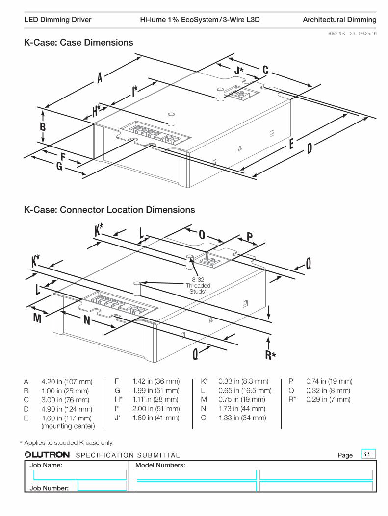
K-Case: Case Dimensions
K-Case: Connector Location Dimensions
B
FG
J* C
H*
A
E D
I*
M N
O P
R*
K*
Q
L
K*
Q
L
A 4.20 in (107 mm)
B 1.00 in (25 mm)
C 3.00 in (76 mm)
D 4.90 in (124 mm)
E 4.60 in (117 mm) (mounting center)
F 1.42 in (36 mm)
G 1.99 in (51 mm)
H* 1.11 in (28 mm)
I* 2.00 in (51 mm)
J* 1.60 in (41 mm)
K* 0.33 in (8.3 mm)
L 0.65 in (16.5 mm)
M 0.75 in (19 mm)
N 1.73 in (44 mm)
O 1.33 in (34 mm)
P 0.74 in (19 mm)
Q 0.32 in (8 mm)
R* 0.29 in (7 mm)
* Applies to studded K-case only.
8-32 Threaded
Studs*

SPECIF ICAT ION SUBMITTAL Page
Job Name:
Job Number:
Model Numbers:
LED Dimming Driver Hi-lume 1% EcoSystem / 3-Wire L3D Architectural Dimming
369325k 34 09.29.16
D
C
B A
M-Case: Case Dimensions
A 14.125 in (359 mm)
B 13.68 in (347 mm) (mounting center)
C 1.18 in (30 mm)
D 1.00 in (25 mm)
K-Case: Side Entry Connector Location Dimensions (Non-Studded)
S
UV
TS 1.38 in (35 mm)
T 0.64 in (16 mm)
U 0.88 in (22 mm)
V 1.53 in (39 mm)
SPECIF ICAT ION SUBMITTAL Page
Job Name:
Job Number:
Model Numbers:
LED Dimming Driver Hi-lume 1% EcoSystem / 3-Wire L3D Architectural Dimming
369325k 35 09.29.16
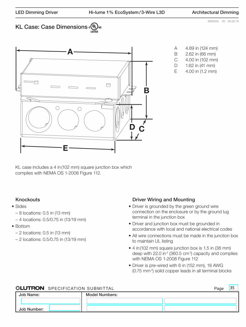
KL Case: Case Dimensions
KL case includes a 4 in (102 mm) square junction box which
complies with NEMA OS 1-2008 Figure 112.
A
B
CD
E
A 4.89 in (124 mm)
B 2.62 in (66 mm)
C 4.00 in (102 mm)
D 1.62 in (41 mm)
E 4.00 in (1.2 mm)
Knockouts• Sides
– 8 locations: 0.5 in (13 mm)
– 4 locations: 0.5/0.75 in (13/19 mm)
• Bottom
– 2 locations: 0.5 in (13 mm)
– 2 locations: 0.5/0.75 in (13/19 mm)
Driver Wiring and Mounting• Driver is grounded by the green ground wire
connection on the enclosure or by the ground lug
terminal in the junction box
• Driver and junction box must be grounded in
accordance with local and national electrical codes
• All wire connections must be made in the junction box
to maintain UL listing
• 4 in (102 mm) square junction box is 1.5 in (38 mm)
deep with 22.0 in 3 (360.5 cm 3) capacity and complies
with NEMA OS 1-2008 Figure 112
• Driver is pre-wired with 6 in (152 mm), 18 AWG
(0.75 mm 2) solid copper leads in all terminal blocks
SPECIF ICAT ION SUBMITTAL Page
Job Name:
Job Number:
Model Numbers:
LED Dimming Driver Hi-lume 1% EcoSystem / 3-Wire L3D Architectural Dimming
369325k 36 09.29.16
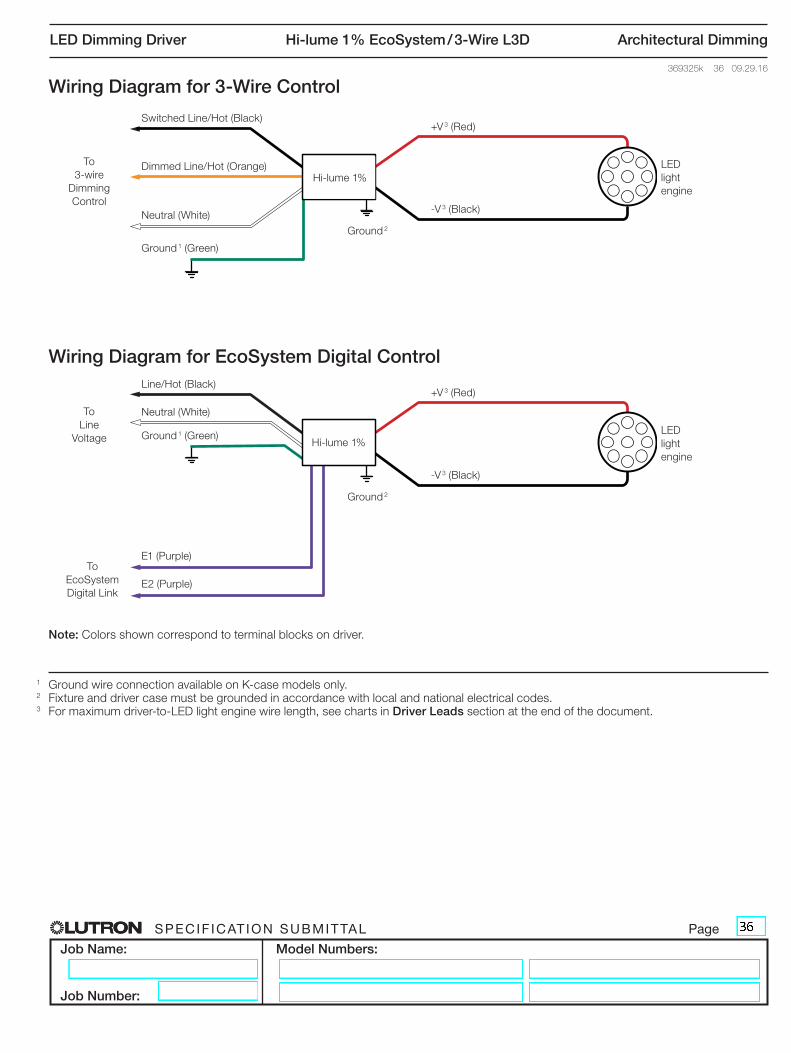
Wiring Diagram for 3-Wire Control
Wiring Diagram for EcoSystem Digital Control
1 Ground wire connection available on K-case models only. 2 Fixture and driver case must be grounded in accordance with local and national electrical codes. 3 For maximum driver-to-LED light engine wire length, see charts in Driver Leads section at the end of the document.
Note: Colors shown correspond to terminal blocks on driver.
Switched Line/Hot (Black)
Dimmed Line/Hot (Orange)
Neutral (White)
Ground 1 (Green)
To
3-wire
Dimming
Control
Ground 2
Hi-lume 1%
-V 3 (Black)
+V 3 (Red)
LED
light
engine
Line/Hot (Black)
E1 (Purple)
Neutral (White)
Ground 1 (Green)
To
Line
Voltage
Ground 2
Hi-lume 1%
-V 3 (Black)
+V 3 (Red)
LED
light
engine
E2 (Purple)
To
EcoSystem
Digital Link
SPECIF ICAT ION SUBMITTAL Page
Job Name:
Job Number:
Model Numbers:
LED Dimming Driver Hi-lume 1% EcoSystem / 3-Wire L3D Architectural Dimming
369325k 37 09.29.16
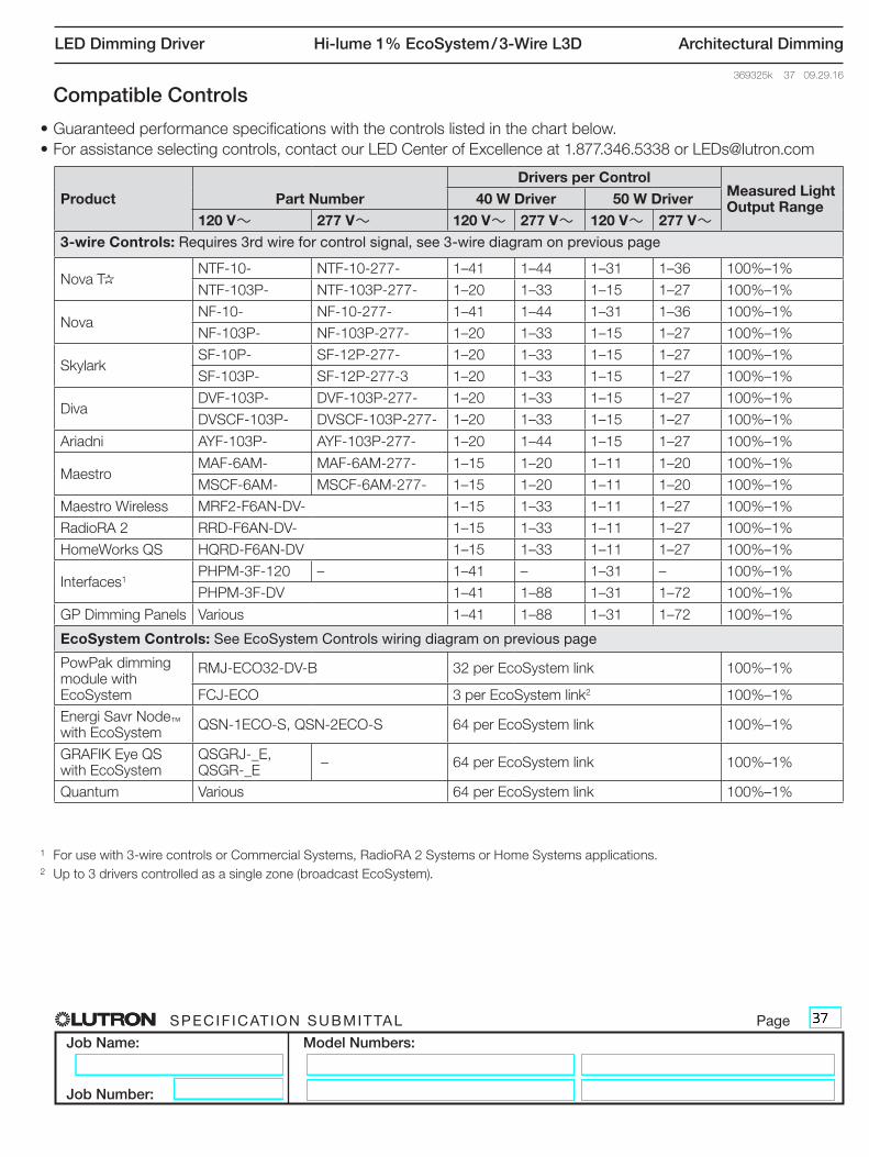
Compatible Controls
• Guaranteed performance specifications with the controls listed in the chart below.
• For assistance selecting controls, contact our LED Center of Excellence at 1.877.346.5338 or [email protected]
1 For use with 3-wire controls or Commercial Systems, RadioRA 2 Systems or Home Systems applications.
2 Up to 3 drivers controlled as a single zone (broadcast EcoSystem).
Product Part Number
Drivers per ControlMeasured Light Output Range
40 W Driver 50 W Driver
120 V~ 277 V~ 120 V~ 277 V~ 120 V~ 277 V~
3-wire Controls: Requires 3rd wire for control signal, see 3-wire diagram on previous page
Nova T*NTF-10- NTF-10-277- 1–41 1–44 1–31 1–36 100%–1%
NTF-103P- NTF-103P-277- 1–20 1–33 1–15 1–27 100%–1%
NovaNF-10- NF-10-277- 1–41 1–44 1–31 1–36 100%–1%
NF-103P- NF-103P-277- 1–20 1–33 1–15 1–27 100%–1%
SkylarkSF-10P- SF-12P-277- 1–20 1–33 1–15 1–27 100%–1%
SF-103P- SF-12P-277-3 1–20 1–33 1–15 1–27 100%–1%
DivaDVF-103P- DVF-103P-277- 1–20 1–33 1–15 1–27 100%–1%
DVSCF-103P- DVSCF-103P-277- 1–20 1–33 1–15 1–27 100%–1%
Ariadni AYF-103P- AYF-103P-277- 1–20 1–44 1–15 1–27 100%–1%
MaestroMAF-6AM- MAF-6AM-277- 1–15 1–20 1–11 1–20 100%–1%
MSCF-6AM- MSCF-6AM-277- 1–15 1–20 1–11 1–20 100%–1%
Maestro Wireless MRF2-F6AN-DV- 1–15 1–33 1–11 1–27 100%–1%
RadioRA 2 RRD-F6AN-DV- 1–15 1–33 1–11 1–27 100%–1%
HomeWorks QS HQRD-F6AN-DV 1–15 1–33 1–11 1–27 100%–1%
Interfaces1PHPM-3F-120 – 1–41 – 1–31 – 100%–1%
PHPM-3F-DV 1–41 1–88 1–31 1–72 100%–1%
GP Dimming Panels Various 1–41 1–88 1–31 1–72 100%–1%
EcoSystem Controls: See EcoSystem Controls wiring diagram on previous page
PowPak dimming module with EcoSystem
RMJ-ECO32-DV-B 32 per EcoSystem link 100%–1%
FCJ-ECO 3 per EcoSystem link2 100%–1%
Energi Savr Node™ with EcoSystem
QSN-1ECO-S, QSN-2ECO-S 64 per EcoSystem link 100%–1%
GRAFIK Eye QS with EcoSystem
QSGRJ-_E, QSGR-_E
– 64 per EcoSystem link 100%–1%
Quantum Various 64 per EcoSystem link 100%–1%

SPECIF ICAT ION SUBMITTAL Page
Job Name:
Job Number:
Model Numbers:
LED Dimming Driver Hi-lume 1% EcoSystem / 3-Wire L3D Architectural Dimming
369325k 38 09.29.16
EcoSystem Wiring Diagrams
EcoSystem Digital Link Overview• The EcoSystem Digital Link wiring (E1 and E2) connects
the digital ballasts and drivers together to form a lighting
control system.
• Each EcoSystem Digital Link supports up to 64 digital
ballasts, LED drivers or EcoSystem Modules
(e.g. C5-BMJ-16A, C5-XPJ-16A), 32 occupancy sensors
(64 occupancy sensors with Energi Savr Node with
EcoSystem), 16 daylight sensors, and 64 wallstations or
IR receivers.*
• Sensors do not directly connect to Hi-lume 1%
EcoSystem / 3-Wire LED drivers.
• E1 and E2 (EcoSystem digital link wires) are polarity
insensitive and can be wired in any topology.
• An Energi Savr Node unit with EcoSystem, GRAFIK
Eye QS control unit with EcoSystem, PowPak dimming
module with EcoSystem, or Quantum system provides
power for the EcoSystem Digital Link and supports
system programming.*
• All EcoSystem Digital Link programming is completed
by using the Energi Savr app for Apple iPad, iPod Touch
or iPhone mobile digital devices, GRAFIK Eye QS with
EcoSystem, PowPak dimming module with EcoSystem,
or Quantum system.
EcoSystem Digital Link Wiring• Driver EcoSystem Digital Link terminals only accept one
18 AWG to 16 AWG (0.75 mm( to 1.5 mm() solid copper
wire per terminal.
• Make sure that the supply breaker to the Digital Driver
and EcoSystem Digital Link Supply is OFF when wiring.
• Connect the two conductors to the two Digital Driver
terminals E1 and E2 as shown.
• Using two different colors for E1 and E2 will reduce
confusion when wiring several drivers together.
• The EcoSystem Digital Link may be wired Class 1 or
Class 2. Consult applicable electrical codes for proper
wiring practices.
To the EcoSystem Digital Bus and additional drivers
and/or ballasts
Notes• The EcoSystem Digital Link Supply does not have to
be located at the end of the Digital Link.
• EcoSystem Digital Link length is limited by the wire
gauge used for E1 and E2 as follows:
Wire GaugeDigital Link Length (max)
12 AWG 2200 ft
14 AWG 1400 ft
16 AWG 900 ft
18 AWG 550 ft
Wire SizeDigital Link Length (max)
4.0 mm( 828 m
2.5 mm( 517 m
1.5 mm( 310 m
1.0 mm( 207 m
0.75 mm( 155 m
E2E1
E2E1
* PowPak dimming module with EcoSystem provides power for the
EcoSystem Digital Link and can support 32 digital ballasts, LED
drivers or EcoSystem Modules, 6 Wireless Occupancy Sensors,
1 Wireless Daylight Sensor, and 9 Pico Wireless Controllers.
Apple, iPad, iPod Touch, and iPhone are trademarks of Apple Inc., registered in the U.S. and other countries.
Driver Terminals
Driver Terminals

SPECIF ICAT ION SUBMITTAL Page
Job Name:
Job Number:
Model Numbers:
LED Dimming Driver Hi-lume 1% EcoSystem / 3-Wire L3D Architectural Dimming
369325k 39 09.29.16Facilities ManagersNOTE: This equipment has been tested and found
to comply with the limits for a Class A digital device,
pursuant to part 15 of the FCC Rules. These limits
are designed to provide reasonable protection
against harmful interference when the equipment is
operated in a commercial environment. This
equipment generates, uses, and can radiate radio
frequency energy and, if not installed and used in
accordance with the instruction manual, may cause
harmful interference to radio communications.
Operation of this equipment in a residential area is
likely to cause harmful interference in which case the
user will be required to correct the interference at his
own expense.
This device complies with part 15 of the FCC Rules.
Operation is subject to the following two conditions:
(1) This device may not cause harmful interference,
and (2) this device must accept any interference
received, including interference that may cause
undesired operation.
SERVICE
Warranty
For warranty information, please visit
www.lutron.com/driverwarranty
Replacement Parts
When ordering Lutron replacement parts please
provide the full model number. Consult Lutron
Technical Support if you have any questions.
Further Information
For further information, please visit us at
www.lutron.com/hilume1led or contact our LED
Control Center of Excellence at 1.877.346.5338 or
Electricians and ContractorsDriver Leads
Maximum driver–to–LED light engine wire length for Constant-Current Drivers:
Maximum driver–to–LED light engine wire length for Constant-Voltage Drivers:
* Terminal blocks on the drivers accept only solid 18 or 16 AWG (0.75 or 1.5 mm2)
wire. To use wire gauges larger or smaller than this terminal blocks’ rated gauge of
18 or 16 AWG (0.75 or 1.5 mm2) refer to the Terminal Wiring Gauges diagram at
the end of this document. Connect up to 3 ft (0.9 m) of 18 or 16 AWG (0.75 or
1.5 mm2) wire to the LED driver terminal blocks, then connect 14 to 12 AWG (2.5 to
4.0 mm2) or 24 AWG to 20 AWG (0.20 mm2 to 0.50 mm2) up to the length allowed in
the above table.
Wiring and GroundingDriver and lighting fixture must be grounded. Drivers must be installed per national and local electrical codes.
LED Load ReplacementFor Class 2 rated drivers, the LED load can be changed while the driver is installed and powered.
Maximum Driver Operating TemperatureDriver case temperature (tc) must not exceed UL conditions of acceptability in end product.
For 50,000 hour lifetime, driver case temperature (tc)must not exceed:
– 149 °F (65 °C) for 40 W drivers.
– 158 °F (70 °C) for 50 W drivers.
Wire Gauge*
Maximum Lead Length
200 mA to 700 mA
710 mA to 1.50 A
1.51 A to 2.10 A
24 AWG (0.2 mm() 8 ft (2.5 m) 4 ft (1.2 m) 2.75 ft (0.8 m)
22 AWG (0.34 mm() 13 ft (4 m) 6 ft (1.8 m) 4.5 ft (1.5 m)
20 AWG (0.5 mm() 20 ft (6 m) 10 ft (3 m) 7 ft (2 m)
18 AWG (0.75 mm() 30 ft (9 m) 15 ft (4.5 m) 10 ft (3 m)
16 AWG (1.5 mm() 35 ft (10.5 m) 25 ft (7.5 m) 15 ft (4.5 m)
14 AWG (2.5 mm() 50 ft (15 m) 40 ft (12 m) 25 ft (7.5 m)
12 AWG (4.0 mm() 100 ft (30 m) 60 ft (18 m) 40 ft (12 m)
Wire Gauge*
Maximum Lead Length
10 V to 20 V 20.5 V to 40 V
40.5 V to 60 V
24 AWG (0.2 mm() 2.5 ft (0.8 m) 4 ft (1.2 m) 8 ft (2.5 m)
22 AWG (0.34 mm() 4 ft (1.2 m) 6 ft (1.8 m) 12 ft (3.7 m)
20 AWG (0.5 mm() 6 ft (1.8 m) 10 ft (3 m) 20 ft (6 m)
18 AWG (0.75 mm() 10 ft (3 m) 15 ft (4.5 m) 30 ft (9 m)
16 AWG (1.5 mm() 15 ft (4.5 m) 25 ft (7.5 m) 50 ft (15 m)
14 AWG (2.5 mm() 25 ft (7.5 m) 40 ft (12 m) 75 ft (22.5 m)
12 AWG (4.0 mm() 40 ft (12 m) 60 ft (18 m) 100 ft (30 m)

SPECIF ICAT ION SUBMITTAL Page
Job Name:
Job Number:
Model Numbers:
LED Dimming Driver Hi-lume 1% EcoSystem / 3-Wire L3D Architectural Dimming
369325k 40 09.29.16
18 AWG to 16 AWG (0.75 mm2 to 1.5 mm2)
18 AWG to 12 AWG (0.75 mm2 to 4.0 mm2)
24 AWG to 12 AWG (0.2 mm2 to 4.0 mm2)
18 AWG to 16 AWG (0.75 mm2 to 1.5 mm2)
24 AWG to 12 AWG (0.2 mm2 to 4.0 mm2)
Ground*
18 AWG to 16 AWG (0.75 mm2 to 1.5 mm2)
18 AWG to 12 AWG (0.75 mm2 to 4.0 mm2)
* Fixture and driver case must be grounded in accordance with local and national electrical codes. Ground connection to driver case can be accomplished through ground terminal, and/or grounding the case. Ground connection to M case driver (shown) requires connection to stud in fixture.
Terminal Wiring Gauges
Wire colors shown correspond to terminal blocks on driver.
NN/C
LN/CN/CE1E2
N/CN/CN/CN/C
N/C-V
+V
Lutron, )Lutron, Hi-lume, EcoSystem, GRAFIK Eye, PowPak, Quantum, Nova T*, Nova, Skylark, Diva, Ariadni, Maestro, Maestro Wireless, RadioRA, and HomeWorks are
trademarks of Lutron Electronics Co., Inc. registered in the U.S. and other countries. Energi Savr Node, QwikFig, and RadioRA 2 are trademarks of Lutron Electronics Co., Inc.