HI 07. Pibiviesse Trunion Mounted Ball Valves and Ball ... - valve… · ON-OFF ball valves...
24
General Catalogue Rotary Control Valves V R
Transcript of HI 07. Pibiviesse Trunion Mounted Ball Valves and Ball ... - valve… · ON-OFF ball valves...

General CatalogueRotary Control Valves
V
R

2

3
Applicable StandardsList of applicable standards 5General InformationProduct range 6ON-OFF valves 6CAGEBALL control ball valves 6Sizes 6Pressure ratings 6Temperature range 6Materials 6Actuation 7Quality assurance system 7CE marking 7API registrations 7Fire safe certifications 7Applications 7
Technical featuresDesign 8Trunnion mounted balls 8Body joints 8Port sizes 8Stem features 8Seat features 9Emergency seat seal 9Antistatic 9Extended stem 10Extended bonnet 10Pups 10TestingAvailable Non Destructive Tests 11Special tests 12Bending tests 12
CAGEBALL™ ConceptOperational properties 13Self cleaning 13Applications 14Benefits 14Options 14Technical properties 15HYPER CAGEBALL™ ConceptOperational properties 16HYPER CAGEBALL™ Multistage ConceptOperational properties 17GuidelinesGeneral 18Nomenclature 18Valve noise 19Velocity 19Pressure drop 19Dynamic torque 19Turndown 19Applications 20-21CAGEBALL™ Cv TableSizing coefficient Cv 22
Rotary ON-OFF and Control Valves Rotary Control ValvesContents

PRODUCT OVERVIEW
4
On-Off
Sideentry
Topentry
Fullywelded
CageBall HyperCage HyperCageMultistage

53
PIBIVIESSE ball valves are in accordance with API, ASME and B.S. requirements. The following list contains the most important applicable standards for ball valves. PIBIVIESSE valves may be designed, manufactured and tested in accordance with other international standard on request.
Applicable StandardsRotary ON-OFF and Control Valves
API - American Petroleum Institute Spec. 6A Specification for wellhead and christmas tree equipment Spec. 6D Specification for pipeline valves Spec. 17D Specification for subseawellhead and christmas treeequipmentSpec.RP6F Recommended practice for fire testing of valves Spec. 6FA Specification for fire testing ofvalvesStd. 598 Valve inspection and test Std. 605 Large diameter carbon steel flangesStd. 607 Fire test for soft seated quarter -turn valves
ASME - American Societyof Mechanical EngineersASME-B 16.5 Steel pipe flanges and flanged fittingsASME-B 16.10 Face-to-face and end-to-end dimensions of ferrous valves ASME-B 16.25 Butt welding ends ASME-B 16.34 Steel valves - Flanged and butt welding ends ASME-B 31.3 Chemical plant and petroleum refinery piping ASME-B 31.4 Liquid petroleum transportation piping systemsASME-B 31.8 Gas transmission and distribution piping systems ASME-B 46.1 Surface texture
ISO - InternationalOrganization for Standardisation UNI EN ISO 9001Quality managementsystems - Requirements ISO 9004 Quality management systems elements - Guideline for performance improvements
BSI - British Standards InstituteBS-EN 102222 Specification for steel forgings for pressure purposes BS-EN 10213 Specification for steel castings for pressure purposes BS 1560 Steel pipe flanges and flanged fittingsBS 2080 Face-to-face, centre-to-face, end-to-end and centre-to-end dimensions of flanged and butt welding end steel valves for the petroleum, petrochemical and allied industries BS-EN 1092 Flanges and their Joints-Circular flanges for pipes, valves, fittings and accessories, PN designated BS-EN 1515-1 Flanges and their Joints BS 5146 Inspection and test of steel valves for the petroleum, petrochemical and allied industriesBS 5351 Steel ball valves for the petroleum, petrochemical and allied industries BS 6755 Testing of valves
MSS – Manufacturers StandardizationSocietySP 6 Standard finishes for contact faces of pipe flanges and connecting - end flanges of valves and fittings SP 25 Standard marking system for valves, fittings, flanges and unions SP 44 Steel pipeline flanges SP 45 By-pass and drain connection standardSP 55 Quality standard for steel castings-visual method SP 61 Hydrostatic testing of steel valves SP 72 Ball valves with flanged or butt welding ends for general service
NACE - National Associationof Corrosion Engineers MR-01-75 Sulfide stress cracking resistant metallic materials for oil field equipment
CEI/IECIEC 60534 Industrial process control valvesIEC 60529 Degreee S or R protection provided by enclosures (IP CODE)IEC 61508/ SIL/PFD definition & evaluation61511

6
General InformationRotary ON-OFF and Control Valves
Product range
Trunnion MountedON-OFF ball valves
Trunnion MountedCONTROL ball valves
SizesPressure ratingsTemperature rangeMaterials
PIBIVIESSE designs and manufactures a widerange of high performance manually operatedor automated, ON-OFF and CONTROL BallValves for any kind of fluid handled in the oil,gas, water, steam and power generatingindustry. The basic ball valve design is a boltedconstruction which simplifies field service andmaintenance. Our product line is thencompleted with our top entry ball valves thatcan be easily serviced without removing thevalve from the line and with our fully weldedline that is typically used for pipeline/buriedapplication or for sub-sea lines.Side entry-bolted body, top entry and fullywelded are available with Metal or Softseats. Specific designs have been developedfor HIPPS to SIL3, Sub-sea, Cryogenic, HighTemperature, Slurry / Erosive applications inaddition to Three way ball valves and Custommade ball valves.Specifically designed to handle very high flowrates or very high differential pressures ourexclusive and patented CAGEBALL™, HYPERCAGEBALL™ and HYPER SILENT™ conceptshave been integrated with the basic featuresof our trunnion mounted On-Off ball valves. On-off valves: from 1/2” to 60”Control valves: from 1” to 60”From ANSI 150 to ANSI 2500-4500;from API 2000 to API 15000From -196°C (-320°F) to +800°C (+1472°F)All our products are available in a wideselection of materials ranging from LowTemperature Carbon Steel up to Inconel 625,Incoloy 825 and more.
General InformationRotary ON-OFF and Control Valves

Pibiviesse valves can be supplied with all typesof actuators, i.e. pneumatic, hydraulic, Gas OverOil, electric, etc. They are tested as a control unit package priorto delivery.All our manufacturing operations are coveredby a quality assurance program, which hasbeen audited and qualified in accordancewith:ISO 9001 – 2000 & API Q1API 6D – ISO 14313API 6A - ISO 10423API 17DASME sect IIIIEC 61508 SIL 3PED 97/23/ECATEX 94/9/ECPibiviesse has been authorised to manufactureits products with CE logo in accordance withPressure Equipment Directive 97/23/EC sinceJune 2001.Pibiviesse has been granted from theAmerican Petroleum Institute the autorisationto use the API 6A and the API 6D monograms.The API 6A includes the product specificationlevel 4, which is the highest quality levelspecified. Licence numbers are:API 6A nr 0370API 6D nr 0215B.S.5146 – B.S.6755API 6FA – API 607 – API RP6FOil & Gas industryLNG & GTL Gas transmission and distributionPower industry and steam generationPetrochemical industryWater transmission & desalination plants
General InformationRotary ON-OFF and Control Valves
7
Actuation
Quality assurance system
CE Marking
API registrations
Fire safe certificationsApplications

8
All Pibiviesse ball valves are a boltedconstruction which simplifies field service andmaintenance. Top entry valves can be easilyserviced without removing the valve from theline. All the components of the side entry ballvalves and all the internals of the top entryball valves are made of forgings. Only thebody of the top entry ball valves is in the castform. Fully welded ball valves are identicalfrom internals design and materials selectionto side entry valves. All body joints andalternatively also the bonnet joints are weldedto offer 100% leak-free joints.Trunnion mounted balls permit ease ofoperation, minimizing the operating torqueand reducing seat seal wear.Double o-rings, or the combination of o-ringsand gaskets, grant a perfect and safe sealingof body and trunnion. Thus making thePIBIVIESSE ball valves suitable for both aboveground and buried installation.Expansion outlet or conical trim are alsoavailable to keep the unexpected dangerouslimit. (Avoiding high frequency vibration).Antiblowout stem permits the replacement ofthe stem seals with the valve in the fullyclosed position. The stem seal integrity isachieved by the use of three o-rings (or two o-rings and a graphite gasket). The upper o-ring(or the graphite gasket) can be replaced withthe valve in line and under pressure. The ball and stem are separate componentswhich lessens torque. Stem and trunnion aresupported by P.T.F.E. impregnated steel bearingsleeves. Provision for the injection ofemergency sealant is available on request.
Technical featuresRotary ON-OFF and Control Valves
Design
Trunnion mounted ballsBody joints
Port sizesStem features

Independent floating spring loaded seats arealways in contact with the ball to provide aneffective tight seal even at low differentialpressures.Independent upstream and downstream seatspermit draining of fluid from the body cavity,allowing double block and bleed operation.With the single sealing feature, there is anautomatic body cavity release of over pressureto the line through the down stream seat. Double sealing feature (available on request),maintains the sealing capacity of the valveeven in the case of failure of the up streamseats. Body cavity over pressure in this casecan be released through a relief valve toatmosphere.A combination of double sealing features onthe downstream side and single sealing onthe upstream seat is available on request.This configuration maintains the sealingcapacity of the valve in case of failure of theupstream seat and release of the body cavityover pressure through the upstream seat.An emergency sealant injection system isavailable on request which can restore thesealing integrity if damage is caused to thesealing surfaces. A stainless steel or Inconel spring betweenthe stem and the ball or between the stemand the gland plate permits electricalcontinuity between all valve components.
Technical featuresRotary ON-OFF and Control Valves
9
Seats features
Emergency seat seal
Antistatic

10
When ball valves are to be installed belowground on buried pipelines or where not easilyaccessible, operators can be remote mountedby means of suitable stem extension. Drainlines and grease injectors (if required) will bepiped up to the top of the extension for aneasier access. The distance between valve centreline andoperator handwheel must be specified.
Ball valves to be used in lowtemperature/cryogenic service are equippedwith extended bonnet to allow vapour spacebetween body cavity and gland seals. This feature preserves stem seals fromdamages that may occur during operation atcryogenic temperatures, and allows stem sealservicing even on valves installed on insulatedlines. Vapour space length or insulatingthickness shall be specified.
Butt welding ends valves may be suppliedwith transition pieces (PUPS) to avoid any riskof seat and seal damage during welding andpost weld heat treatment operations. Length of pups and matching pipe detailsmust be specified.
Technical featuresRotary ON-OFF and Control Valves
Extended stem
Extended bonnet
Pups

Available Non Destructive Tests
Other additional non destructive or destructive examinations may be performed to customer requirements or specifications. Please contact our Q.A.or Q.C. departments for additional information and clarification.
TestingRotary ON-OFF and Control Valves
11
DESCRIPTION OF TEST APPLICABLE STANDARDS EXTENT OF TEST
Upon customer requestPIBIVIESSE procedures and customerspecificationsHigh pressure gas test100% of wetted componentsNACE MR01-75Hardness
Upon customer requestPIBIVIESSE procedures for Thermo Scientific Niton XLT 898Spectro-Ametek SPECTROTEST CCDAlloy verification
100% of rough and finished machinedcomponents and assembled partsApplicable ASTM StdsMSS-SP44 and SP55ASME B16.34, B16.5, B16.10API 6D and 6A, BS 2080
Visual and dimensional
100% of actuated valves10% of manual valvesAPI 6D and customer requirementsStem torque
100% of all valvesAPI 6D and API 6ABS 5146 and BS 6755MSS-SP61 and customer specsHydrostatic and pneumatic
Upon customer request ASME V – Art. 4 and 23ASME VIII – Div.1ASTM A388Ultrasonic
Upon customer requestASME V – Art. 2 and 22ASME VIII – Div.1ASME B16.34 – Appendix IASTM E142 - E94 - E446 - E186 - E280
X and Gamma ray
10% on pressure containing partsFor non magnetic materials(100% upon customer request)ASME V – Art. 7 and 25ASTM E709ASME B16.34 – Appendix II
Magnetic particles (dry and wet)
10% on pressure containing partsFor non magnetic materials(100% upon customer request)ASME V – Art. 6 and 24ASTM E165ASME B16.34 – Appendix III
Dye Penetrant
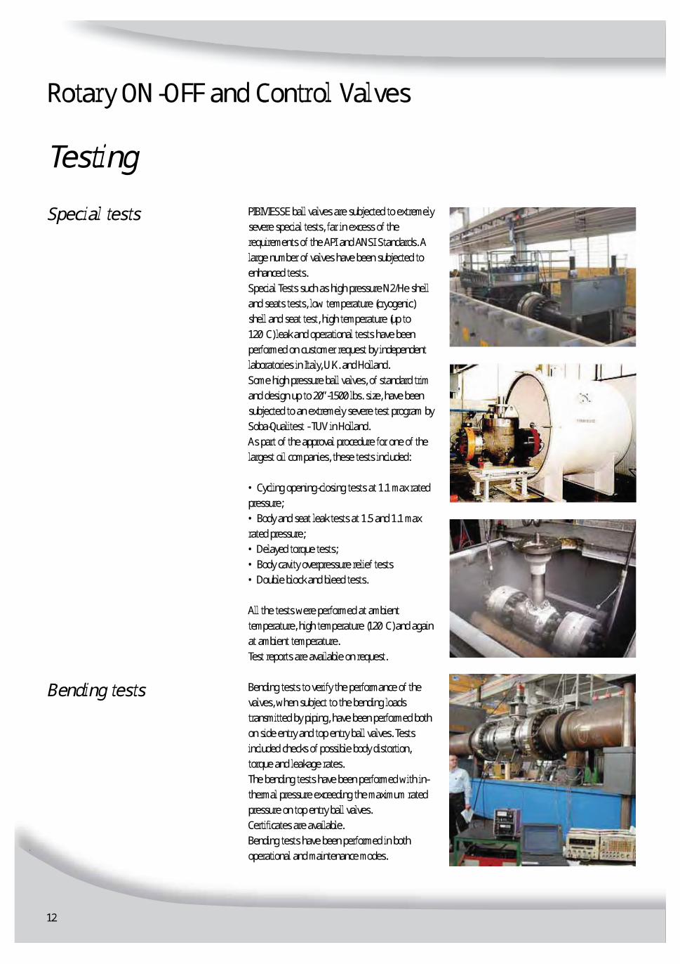
PIBIVIESSE ball valves are subjected to extremelysevere special tests, far in excess of therequirements of the API and ANSI Standards. Alarge number of valves have been subjected toenhanced tests. Special Tests such as high pressure N2/He shelland seats tests, low temperature (cryogenic)shell and seat test, high temperature (up to120°C) leak and operational tests have beenperformed on customer request by independentlaboratories in Italy, U.K. and Holland. Some high pressure ball valves, of standard trimand design up to 20”-1500 lbs. size, have beensubjected to an extremely severe test program bySoba-Qualitest - TUV in Holland. As part of the approval procedure for one of thelargest oil companies, these tests included: • Cycling opening-closing tests at 1.1 max ratedpressure;• Body and seat leak tests at 1.5 and 1.1 maxrated pressure; • Delayed torque tests; • Body cavity overpressure relief tests • Double block and bleed tests. All the tests were performed at ambienttemperature, high temperature (120°C) and againat ambient temperature. Test reports are available on request. Bending tests to verify the performance of thevalves, when subject to the bending loadstransmitted by piping, have been performed bothon side entry and top entry ball valves. Testsincluded checks of possible body distortion,torque and leakage rates. The bending tests have been performed with in-thermal pressure exceeding the maximum ratedpressure on top entry ball valves. Certificates are available. Bending tests have been performed in bothoperational and maintenance modes.
TestingRotary ON-OFF and Control Valves
12
Special tests
Bending tests

13
Pibiviesse Cage-Ball control valves are enhancedsecond generation of control ball valve design. Itis based on changeable internal cage whichdivides the pressure drop in stages.The attenuating plates, mounted into areplaceable cartridge, are offset by an optimallydesigned angle to obtain a number of significantcontrol advantages. The noise, cavitation andhigh frequency vibration are almost eliminated. The turndown is increased to 250.The new balancing tails significantly reduce thedynamic forces generated by the attenuatingplates.This balanced trim offers the followingadvantages: lower torques, increased accuracy,ease of operation and reduced load on the stemmodule.Extra large bearings can handle pressure anddynamic loads and vibrations do not affect Cage-Ball valves performance. This guaranteesstability during throttling operation.
A new feature is the self-cleaning effect builtin the trim design. When the valve is in largeopenings (this happens if the attenuating platesare plugged by dirt or solid that might be in theflowing medium) the angle between the flowaxis and the plates is optimal to generate adepressurization behind the plates. This cleansthe plugged holes and significant savings onthe maintenance can be achieved.
CAGEBALLTM ConceptRotary Control Valves
Operational properties
Self cleaning

14
Due to high flow factors as FL, Xt and Z alongwith exceptional flow capacity, Cage-Ballvalves give optimal solutions in various severecontrol applications like:Flow control on loading arms (including top-ups) – Pumps and system start-ups – Partialthrottling – Compressor control.By-pass on transmission lines – Surge relief –Smooth depressurizations –Equalization/balancing and venting.Blow-down (with reduced Hydrate formation)– Switching (where smooth transitions arerequired).
Benefits include economy in large mass flow-rates, low noise and/or non-cavitating fluidhandling, axial flow in large flow-rates alsomeans lower turbulence, vibrations andbalanced constant torque development.Extra safety factors can be smaller in sizingactuators, meaning savings in actuator size,control accessories and air consumption.
These control valves can have reduced trim orexpanded outlet equipped with integratedflow restrictor resulting in linear flowcharacterization or constant Dp over the valve.In addition with a large choice of materialsand seating arrangements, combined with fullor reduced bore configurations the Cage-Ballcontrol valves can be tailored to suit actualservice conditions.
CAGEBALLTM ConceptRotary Control Valves
Applications
Benefits
Options

15
The operational properties mentioned in theprevious paragraphs have some technicalfeatures that make Pibiviesse Cage-Ball valvesunique. The major points are listed herebelow.Fig 1) and Fig 1A) show how upper and lowersupport plates are designed for heavy dutyservice. The wide diameter bearings carrysafely the pressure loads and thus minimizevalve frictions and vibrations.Fig 2) The stem is designed to be backlashfree and not subject to bending with the
benefit of smoother operation and stem sealslong-lasting life.Fig.3) The seat is designed to be pressureassisted only when the ball is in fully closedposition assuring smooth operability inmodulating service. This means a significantreduction in ball surface wearing and longterm bidirectional tight shut-off is achieved.Upstream sealing seat is not subject to flowerosion or impingement.Fig.4) The structural integrity of the balldesign is made of the most robust by
machining the trunnion to spherical geometry.This avoids the deformation while throttlingunder the fully rated pressure differentials.The trunnions and consequently the bearingsare generously designed with very lowspecific load allowing long lasting smoothbackflash free operation.The ball and the Cage-Ball cartridge arebidirectional and in case of excessive weartha ball can be simply rotated by 180°.By changing the seat the valve can beupgraded tight.
CAGEBALLTM ConceptRotary Control Valves
Technical propertiesFig. 2 Fig. 4
Fig. 3
Fig. 1
Fig. 1A
Cross Section A-A
16
HYPER CAGEBALLTM Trim ConceptRotary Control Valves
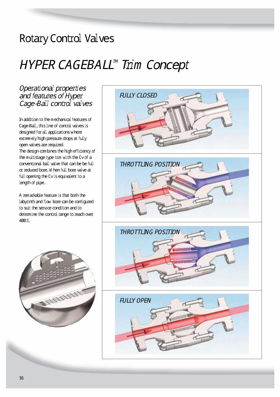
In addition to the mechanical features ofCage-Ball, this line of control valves isdesigned for all applications whereextremely high pressure drops at fullyopen valves are required.The design combines the high efficiency ofthe multistage type trim with the Cv of aconventional ball valve that can be be fullor reduced bore. When full bore valve atfull opening the Cv is equivalent to alength of pipe.A remarkable feature is that both thelabyrinth and flow bore can be configuredto suit the service condition and todetermine the control range to reach over400:1.
Operational propertiesand features of HyperCage-Ball control valves FULLY CLOSED
THROTTLING POSITION
THROTTLING POSITION
FULLY OPEN

17
HYPER CAGEBALLTM Multistage Trim ConceptRotary Control Valves
This valve design combines the advantages ofour Cage-Ball control valve with theadvantages of our Hyper Cage-Ball.This design has been developed to allowsmooth control of high/medium pressure dropwith very small initial flow and very large flowat full opening while maintaining anti-cavitation and self-cleaning features.Also for this configuration the CV values canbe customized to better suit the variousservice conditions.One of the most common application of thisdesign is for turbine’s start-up, wheregenerally two valves in split-range are used.Due to nature of Hyper Cage design thecapacity is always made suitable for theapplication.Pibiviesse engineers shall design the bestexecution of the cartridge design based on thegiven process conditions.
Operational propertiesand features of MultistageHyper Cage-Ballcontrol valvesFULLY CLOSED
THROTTLING POSITION
THROTTLING POSITION
FULLY OPEN

18
Selection of a control valve is a three phaseprocess. Firstly the mechanical suitability of thevalve according to pressures, temperatures,flowing fluid and as well local laws and rules.Secondly comes the physical valve sizing to becapable to pass convenient flow through thevalve with acceptable margins of safety andnoise generation. Thirdly the valve controlbehaviour must be suitable to meet the controlloop (process) requirements.Mechanical selection is based on goodengineering practise and knowledge of theprocess fluid nature and behaviour (corrosion,erosion, mechanical strength etc). Valve sizing isbased on given flow parameters. What isexpected from the valve from capacity and noisewise. Wrong sizing can also affect valve wearand thus life time. In process performance,design control valves sizing can affect theprocess performance and efficiency.Typical mistakes are too small valves leading totoo high opening angle or too big valves leadingto too small opening. Both can cause seriousproblems in control accuracy, noise and alsovalve mechanical life time. Valve behaviour incontrol loop is related to valve internalcharacteristics (design). The characteristics are linear equal percentage ormodified. The effect to flow is dependant of thevalve opening.
Capacity (Cv / kv) = Valve flow coefficientwhich represents the capacity of a particularvalve design. It is calculated and measured inlaboratory and is listed in a table per every 10%of valve opening. Especially at small openings tointermediate Cage Ball is offering higher capacitycompared to conventional solutions.
GuidelinesRotary Control Valves
General
Nomenclature

19
The biggest portion by far of noise is caused bycavitation in liquid flow. Generally it can be saidthat by controlling the velocity the noise gets takencare. The second noise source is large valves massflow rates. Large size valves have normally smallerwall thickness which does not absorb the noisethus the noise level can be high. Flow pathmodification with Cage or Hyper-Cage shall be themost suitable solution to outcome from theseproblems.Flow velocity is an initiator of many valveperformance measures. When the flow area withinthe valve internals is restricted constant flowneeds increased velocity to pass the valve.Increased velocity is the cause of noise generation,erosion, cavitation, chocked flow, corrosion, pipevibration, etc. By splitting the pressure steps intoseveral stages, by means of Cage Ball the velocityis reduced to level which does not cause flowdisturbance.Pressure drop is the pressure loss caused by thevalve. Inlet pressure P1 – outlet pressure P2 =pressure drop. When selecting the valve for acontrol duty it is very important that the mechanicalvalve design can withstand the pressure drop deltaP also within the given process conditions.Under differential pressure conditions the flowtends to open or close the valve. This is caused byan asymmetric pressure distribution on the surfaceof ball. This must be taken into account whenselecting the actuator. Cage Ball balancing tailsdivide the dynamic forces evenly inside the triminternals and therefore reduce the dynamic forces.The ratio of plant maximum design flow rate tominimum designed flow rate. Cage and HyperCage Ball design have brought the turndown to alevel of 1:250 or even higher. These turndownratios have not been available with anyconventional solutions till now.
GuidelinesRotary Control Valves
Valve noise
Velocity
Pressure Drop
Dynamic torque
Turndown

20
GuidelinesRotary Control Valves
ApplicationsCage Ball and Hyper Cage Ball valves can be used in most low noise flow control applications where control accuracy is needed. It offers an axial flow throughthe valve port and thus eliminates several difficulties created by turbulent flow. The main benefits are still in High Pressure drop or Cavitating applications.
Compressor Anti-surgeCompressor By-passRegasificationBlowdownMetering StationsFlare depressuring
Steam ControlNoise ControlCooling waterLarge Flow ControlDesuperheating
Compressor Anti-SurgeCompressor By-passCompressor/pump recirculationPressuring/depressuringLoading controlPump Start-upCavitation controlNoise & Vibration controlErosion controlReducing StationsMixing & Metering
Oil & Gas
LNG
Power Industry

21
GuidelinesRotary Control Valves
Cavitation ControlNoise & Vibration ControlErosion ControlHigh RangeabilityClogging
Compressor Anti-surgeCompressor By-passBlowdownFeed stock feedPressure ControlTemperature ControlFlow ControlLevel ControlScaling & Coking and Slurry Fluids Control
Refining &Petrochemical
Desalination& Water
General
Steam to Brine heaterDesuperheating∆p Control
But in any steam, liquids, oil, gas, hydrates and erosive applications these valves are the most suitable. Also applications which need smooth switching or selfcleaning benefit from the Cage Ball design. We list here a few applications by industry where Pibiviesse Cage Ball valves have been used:


23

Johannesburg Tel : 011-397 2833
Fax : 011-397 4700
E-mail : [email protected]
Durban Tel : 031-579 2593
Fax : 031-579 2562
E-mail : [email protected]
www.valve.co.zaV
R