HG200 Non gas - Lascentrum Norge
25
Head office: 16th floor of Wework Building, 507 Teheran-ro, Gangnam-gu, Seoul TEL: (02) 6230-6041 FAX: (02) 598-8467 Pohang Plant 2: 99 Yeongil Mansandan-ro 88beon-gil, Heunghae-eup, Buk-gu, Pohang-si, Gyeongsangbuk-do TEL: (054) 260 0664 FAX: (054) 260 0599 HG200 Non gas User manual To use this product correctly and safely Please read this manual thoroughly before using, checking or repairing the product.
Transcript of HG200 Non gas - Lascentrum Norge

Head office: 16th floor of Wework Building, 507 Teheran-ro,
Gangnam-gu, Seoul
TEL: (02) 6230-6041 FAX: (02) 598-8467
Pohang Plant 2: 99 Yeongil Mansandan-ro 88beon-gil, Heunghae-eup,
Buk-gu, Pohang-si, Gyeongsangbuk-do
TEL: (054) 260 0664 FAX: (054) 260 0599
HG200 Non gas
User manual
To use this product correctly and safely
Please read this manual thoroughly before using, checking or repairing the product.

1
CONTENTS - 1.Safety……………………..………………..…………………………….…..……....……………………………………………………. 2
- 2.General Description……...………......……...…………………….………...……….....……………………………………….. 3
-3.Main Parameter…….……...…...........…….....………………………………….…..……….…………………………………… 5
- 4.Structure of welder…….……...…...........………………………..…………….…..……….…………………………………… 6
-5.Installation ………………………………………………………………………………………………………………………………….. 7
-6.Welding settings quick reference chart………………………………………………………………………………………. 11
- 7.Range of welding current and voltage in CO2 welding...……….…………………………………………………… 16
- 8.Welding parameters table.......…....................……………………….………..…………………………………………… 17
- 9.Caution……….....................…………………………………………...………………. .....…...................................... 19
- 10. Maintenance….………………………………………….……………….….……....….…………………………………………… 20
- 11. Daily checking……………………………………….….……....….………………………………………….…………………….. 21
- 12. Connection diagram of the machine………………………………….….……....….………………………………….. 23
- 13. Explosion drawing…………………………..………………………………….….……....….………………………………….. 24
This welding machine for industrial and professional use is in conformity with IEC974 International Safety Standard.
Hereby we state that we provide 6 months of guarantee for this welding machine since the date of purchase.
Please read and understand this instruction manual carefully before the installation and operation of this machine. The contents of this manual may be revised without prior notice. This instruction manual is issued in October 2019.

2
1.SAFETY
Welding and cutting is dangerous to the operator, people in or near the working area, and the surrounding,
if the machine is not correctly operated. Therefore, the performance of welding/cutting must only be
under the strict and comprehensive observance of all relevant safety regulations. Please read and
understand this instruction manual carefully before the installation and operation.
·The switching of function modes is possibly damaging to the machine, while the
welding operation is performed.
·Do disconnect the electrode-holder cable with the machine, before the
performance of welding.
·A safety switch is necessary to prevent the machine from electric-leakage.
·Welding tools should be of high quality.
·Operators should be qualified.
Electric shock: It could be fatal!
·Connect the earth cable according to standard regulation.
·Avoid all contact with live electrical parts of the welding circuit, electrodes and
wires with bare hands. It is necessary for the operator to wear dry welding
gloves while he performs the welding task.
·The operator should keep the working piece insulating from himself/herself.
Smoke and gas generated while welding or cutting: harmful to people’s
health.
·Avoid breathing the smoke and gas generated while welding or cutting.
·Keep the working area well ventilated.
Arc rays: harmful to people’s eyes and skin.
·Wear welding helmet, anti-radiation glass and work clothes while the welding
operation is performed.
·Measures also should be taken to protect people in or near the working area.
Fire hazard
·The welding splash may cause fire, thus remove flammable material away from
the working place.
·Have a fire extinguisher nearby, and have a trained person ready to use it.
Noise: possibly harmful to peoples’ hearing.
·Noise is generated while welding/cutting, wear approved ear protection if noise
level is high
Machine fault:
·Consult this instruction manual.
·Contact your local dealer or supplier for further advice.

3
2.GENERAL DESCRIPTION
This welding machine is composed of the inverter MIG welder power supply with invariable voltage output
external characteristics manufactured with advanced IGBT inverter technology designed by our company.
With high-power component IGBT, the inverter convert the DC voltage, which is rectified from input
50Hz/60Hz AC voltage, to high-frequency 20KHz AC voltage; as a consequence, the voltage is transformed
and rectified. The features of this machine are as follows:
● IGBT inverter technology, current control, high quality, stable performance;
● Closed feedback circuit, invariable voltage output, great ability of balance voltage up to ±15%;
● Electron reactor control, stable welding, little splash, deep molten pool, excellent welding bead shaping;
● Welding voltage can be preset, and the voltmeter displays the preset voltage value when not welding.
● Both welding current and welding voltage can be observed at the same time.
● Burnback time is adjustable.
● Slow wire feeding during arc starting, remove the melting ball after welding,reliable arc starting;
● Wire feeding part is separated from the welding machine, wide welding operation range.
● Small-sized, light-weighed, easy to operate, economical, practical.
Unpacking your machine
When unpacking, inspect carefully for any damage that may have occurred during transit. Check
carefully to ensure all the contents on the list below have teen received in good condition
Included items:
No. Description Qty. Pic
1 MIG Welder 1set
2 Operator’s Manual 1pc
3 Electrode Holder 1pc
4
Earth Clamp 1pc
5 3m MIG torch 1pc
Operating environment
Adequate ventilation is required to provide proper cooling for the MIG-E. Ensure that the machine is
placed on a stable level surface where clean cool air can easily flow through the unit. The MIG-E
has electrical components and control circuit boards which will be damaged by excessive dust
and dirt, so a clean operating environment is essential

4
Block Diagram
LIFT TIG also called the contact type arcing TIG.
Needed items: inverter welder with LIFT TIG function, contact type MIG gun with one output power cable and one air
tube.
The use way of LIFT TIG is shown as below:
The output power cable connect with the negative output terminal, and the air tube connect with the gas meter on the
argon gas bottle. There is a nut cover on the air tube, which can connect with the gas meter. The thread specification for
the gas meter and the nut should be the same. Then open the valve of the argon gas bottle and open the valve of the gas
meter, we can control the gas flow by adjusting the gas regulating valve on the TIG gun. Make the tungsten needle touch
the workpiece, lift the TIG gun up by little, then we can see the arcing.
3. MAIN PARAMETER
INPUT
CONTROL

5
3.MAIN PARAMETER
Note : The welding duty cycle is the percentage of actual continuous welding time that can occur in a ten minute cycle. For
example: 15% at 200amps- this means the welder can weld continuously at 200 amps for 1.5 minutes and then the unit
will need to be rested for 8.5 minutes.
The duty cycle can be affected by the environment in which the welder is used. In areas with temperatures exceeding
40℃, the duty cycle will be less than stated. In areas less than 40 ℃, higher duty cycles have been obtained
All tests on duty cycles have been carried out at 40℃ with a 50%. So in practical working conditions the duty cycles
will be much greater than those stated above.
MODEL HG-200
Power supply voltage 230±10%
Rated input capacity 7.8 6 7.5
Rated Frequency(Hz) 50/60
Rated input current 35\16 26\12 33\18
Output current range 50-200 10-200 10-160
Function MIG TIG MMA
Duty cycle(40℃ 10min)
20% 200A 20% 200A 20% 160A
60% 120A 60% 120A 60% 90A
100% 90A 100% 90A 100% 70A
No load voltage 51
Efficiency 85
Power factor 0.76
IP 21S
Insulation class H
Cooling way FAN & AIR
Dimension 450x180x290
Wire diameter 0.6-0.8-0.9-1.0 Ø 2.6,Ø 3.2
Electrode type 6013,7018,etc.
Net weight 8.5

6
4. Structure of welder
2
1
4
6
8
11
3
5
7
9
10
1. Gas selection
2. VRD/2T/4T Selection function
3. welding mode selection button: MMA/LIFT
TIG/MIG
4. Voltage/voltage refine/error digital display
5. Current/inductance/wire feed speed digital
display
6. Wire diameter (Synergy) selection /Separate
mode
7. Gas check
8. Wire check
9. welding parameter adjustment knob
10. Function button: adjust the inductance in MIG
mode; adjust the hot start and arc force in
MMA mode.
11. MIG Torch ‘Euro Style’ Connection Socket
12. Positive (+) Welding Output Terminal
13. Negative (-) Welding Output Terminal
14. Polar conversion line
18. Wire tension adjustment
19. Wire tension arm & support roller
20. Wire input guide
21. Wire drive roller
22. Drive roller retainer
23. wire spool retainer
24. Spool brake adjustment
12
13 14
15
16 17
15. welding gas inlet
16. power switch
17. power cable

7
5.INSTALLTION
5.1. MIG Welding Set Up & Operation
5.1.1 Fitting the spool
5.1.1.1 open the cover door for the wire feed compartment. Remove the wire spool retainer(23) by threading off anti
clockwise.
5.1.1.2 fit the 200mm diameter wire spool to the spool holder, ensuring the end of the wires exits towards the wire
feeder from the bottom of the spool. Refit the wire spool retainer(23) and tighten finger tight.
5.1.1.3 set the spool brake tension by rotating the adjustment screw(24) using an Allen wrench. Clockwise to increase
brake tension, anti-clockwise to decrease brake tension. The spool brake tension should be set so that the spool can
rotate freely, but does not continue to rotate once the wire feed stops. This may need to be adjusted as the wire is used
up and the spool weight decreases.
5.1.2 Loading wire feeder
5.1.2.1 release the wire feeder tension arm(19) by pivoting the wire feed tension adjuster(18) as pictured below
25. Torch trigger switch
26. Torch “Euro” connector
27. Workpiece earth clamp
28. Earth lead quick connector
29. Conical gas nozzle/shroud
30. Welding MIG
31. Shroud spring
32. MIG adapter
25
26
27
28
29 30 31
32

8
5.1.2.2 check the wire drive roller(21) groove matches the selected MIG wire type and size. The drive roller will have two
different sized grooves, the size of the groove in use is stamped on the side of the drive roller. For flux cored ‘soft’
wire ,such as that used in gasless MIG welding, the drive roller groove has a serrated profit. For solid ‘hard’ MIG wire, the
roller groove has a ‘v’ shaped profile
5.1.2.3 the drive roller(21) is removed by threading the drive roller retainer(22) off in the anti-clockwise direction. Once
the correct drive roller profile is selected, re-fit the drive roller.
5.1.2.4 thread the MIG wire from the spool through the input guide tube(20), through the roller groove and into the
outlet guide tube
5.1.2.5 Replace the tension arm (19) and the tension adjustment (18). Double check the wire has located correctly in
the drive roller groove.
5.1.2.6 Adjusting wire feed tension: this is accomplished by winding the knob on the wire tension adjustment arm (18).
Clockwise will increase tension, anti-clockwise will decrease tension. There is a numbered scale on the tensioner to
indicate the position. Ideal tension should be as little as possible, while maintaining a consistent wire feed with no drive
roller slippage. Check all other possible causes of slippage, such as; incorrect/ worn drive roller, worn/ damaged torch
consumables, blocked/ damaged torch feed liner, before increasing feed tension.
Warning! - Before changing the feed roller or wire spool, ensure that the mains power is switched off
Warning! - The use of excessive feed tension will cause rapid and premature wear of the drive roller, the support
bearing and the drive motor.
5.1.3 setup for gasless MIG welding operation
5.1.3.1 Connect the MIG Torch Euro Connector (26) to the torch socket on the front of the welder (11). Secure by firmly
hand tightening the threaded collar on the MIG Torch Euro Connector clockwise.
5.1.3.2 Check that the correct flux cored, gasless wire, matching drive roller (21) and welding tip (30) are fitted
5.1.3.3 Connect Torch Connection Power Lead (14) to the negative (-) welding output terminal (13).
5.1.3.4 Connect Earth Lead Quick Connector (28) to the positive (+) output welding terminal (12). See picture below.
5.1.3.5 Connect Earth Clamp (27) to the work piece. Contact with workpiece must be strong contact with clean, bare
metal, with no corrosion, paint or scale at the contact point.
5.1.4 Setup for gas shielded MIG welding operation
Note - Gas shielded MIG welding requires a shielding gas supply, gas regulator and gas shielded MIG wire. These
accessories are not supplied standard with the RW1500MP. Please contact your local Repco branch for details
5.1.4.1 Connect the MIG Torch Euro Connector (26) to the torch socket on the front of the welder (11). Secure by firmly
hand tightening the threaded collar on the MIG Torch Euro Connector clockwise.
5.1.4.2 Check that the correct gas shielded wire, matching drive roller (21) and welding tip (30) are fitted
5.1.4.3 Connect Torch Connection Power Lead (14) to the positive (+) welding output terminal (12)
5.1.4.4 Connect Earth Lead Quick Connector (28) to the negative (-) output welding terminal (13). See picture below
MIG Touch Earth lead

9
Earth lead
MIG Touch
5.1.4.5 Connect Earth Clamp (27) to the work piece. Contact with workpiece must be strong contact with clean, bare metal,
with no corrosion, paint or scale at the contact point.
5.1.4.6 Connect the gas regulator (optional) and gas line to the inlet on the rear panel (15). If the regulator is equipped
with a flow gauge, the flow should be set between 8 – 15 L/minute depending on application. If gas regulator is not
equipped with a flow gauge, adjust pressure so gas can just be heard coming out of the torch conical nozzle (29). It is
recommended that gas flow is checked again, just prior to starting weld This can be done by triggering the MIG torch with
the unit powered up.
1)
Note: Since the arc of MIG welding is much strong than that of MMA welding, please wear welding helmet and protective
clothing.
Connection of Shield Gas
Connect the CO2 hose, which come from the wire feeder to the copper
nozzle of gas bottle. The gas supply system includes the gas bottle, the
air regulator and the gas hose, the heater cable should be inserted into
the socket of machine’s back, and use the hose clamp to tighten it to
prevent leaking or air-in, so that the welding spot is protected.
Please note:
1) Leakage of shielding gas affects the performance of arc welding.
2) Avoid the sun shine on the gas cylinder to eliminate the possible
explosion of gas cylinder due to the increasing pressure of gas
resulted from the heat.
3) It is extremely forbidden to knock at gas cylinder and lay the
cylinder horizontally.
4) Ensure no person is up against the regulator, before the gas
release or shut the gas output.
5) For MIG-250GW and MIG-250GF, insert the power supply plug of
the heater into the 36 VAC (5A) socket on the back panel of the
welding machine.
6) The gas output volume meter should be installed vertically to
ensure the precisely measuring.
7) Before the installation of gas regulator, release and shut the gas
for several time in order to remove the possible dust on the sieve
to avail the gas output.
10
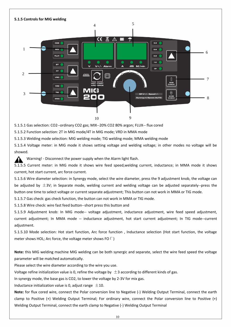
5.1.5 Controls for MIG welding
5.1.5.1 Gas selection: CO2--ordinary CO2 gas; MIX--20% CO2 80% argon; FLUX-- flux cored
5.1.5.2 Function selection: 2T in MIG mode/4T in MIG mode; VRD in MMA mode
5.1.5.3 Welding mode selection: MIG welding mode; TIG welding mode; MMA welding mode
5.1.5.4 Voltage meter: in MIG mode it shows setting voltage and welding voltage; in other modes no voltage will be
showed.
Warning! - Disconnect the power supply when the Alarm light flash.
5.1.5.5 Current meter: in MIG mode it shows wire feed speed,welding current, inductance; in MMA mode it shows
current, hot start current, arc force current.
5.1.5.6 Wire diameter selection: in Synergy mode, select the wire diameter, press the 9 adjustment knob, the voltage can
be adjusted by ±3V; in Separate mode, welding current and welding voltage can be adjusted separately--press the
button one time to select voltage or current separate adjustment; This button can not work in MMA or TIG mode.
5.1.5.7 Gas check: gas check function, the button can not work in MMA or TIG mode.
5.1.5.8 Wire check: wire fast feed button--short press this button and
5.1.5.9 Adjustment knob: In MIG mode-- voltage adjustment, inductance adjustment, wire feed speed adjustment,
current adjustment; In MMA mode -- inductance adjustment, hot start current adjustment; In TIG mode--current
adjustment.
5.1.5.10 Mode selection: Hot start function, Arc force function , Inductance selection (Hot start function, the voltage
meter shows HOL; Arc force, the voltage meter shows FOГ)
Note: this MIG welding machine MIG welding can be both synergic and separate, select the wire feed speed the voltage
parameter will be matched automatically.
Please select the wire diameter according to the wire you use.
Voltage refine initialization value is 0, refine the voltage by ±3 according to different kinds of gas.
In synergy mode, the base gas is CO2, to lower the voltage by 2-3V for mix gas.
Inductance initialization value is 0, adjust range ±10.
Note: for flux cored wire, connect the Polar conversion line to Negative (-) Welding Output Terminal, connect the earth
clamp to Positive (+) Welding Output Terminal; For ordinary wire, connect the Polar conversion line to Positive (+)
Welding Output Terminal, connect the earth clamp to Negative (-) Welding Output Terminal
1
2
3
4 5
6
7
8
9 10

11
6.Welding settings quick reference chart

12
Basic welding guide
MIG (GMAW/FCAW) Basic Welding Technique
Two different welding processes are covered in this section (GMAW and FCAW), with the intention providing the
very basic concepts in using the MIG mode of welding, where a welding gun is hand held, and the electrode (welding wire)
is fed into a weld puddle, and the arc is shielded by an inert welding grade shielding gas or inert welding grade shielding
gas mixture.
GAS METAL ARC WELDING (GMAW): This process, also known as MIG welding, CO2 welding, Micro Wire Welding, short
arc welding, dip transfer welding, wire welding etc., is an electric arc welding process which fuses together the parts to be
welded by heating them with an arc between a solid continuous, consumable electrode and the work. Shielding is
obtained from an externally supplied welding grade shielding gas or welding grade shielding gas mixture. The
process is normally applied semi automatically; however the and fairly thick steels, and some non-ferrous
metals in all positions.
FLUX CORED ARC WELDING (FCAW): This is an electric arc welding process which fuses together the parts to be welded by
heating them with wan arc between a continuous flux filled electrode wire and the work. Shielding is obtained through
decomposition of the flux within the tubular wire. Additional shielding may or may not be obtained from an externally
supplied gas or gas mixture. The process is normally applied semi automatically; however the process may be
applied automatically or by machine. It is commonly used to weld large diameter electrodes in the flat and
horizontal position and small electrode diameters in all positions. The process is used to a lesser
degree for welding stainless steel and for overlay work.

13
Position of MIG Torch The angle of MIG torch to the weld has an effect on the width of the weld
The welding gun should be held at an angle to the weld joint. (See Secondary Adjustment Variables below) Hold the gun so
that the welding seam is viewed at all times. Always wear the welding helmet with proper filter lenses and use the proper
safety equipment.
CAUTION
Do not pull the welding gun back when the arc is established. This will create excessive wire extension (stick-out) and make
a very poor weld.
The electrode wire is not energized until the gun trigger switch is depressed. The wire may therefore be placed on the
seam or joint prior to lowering the helmet.
14
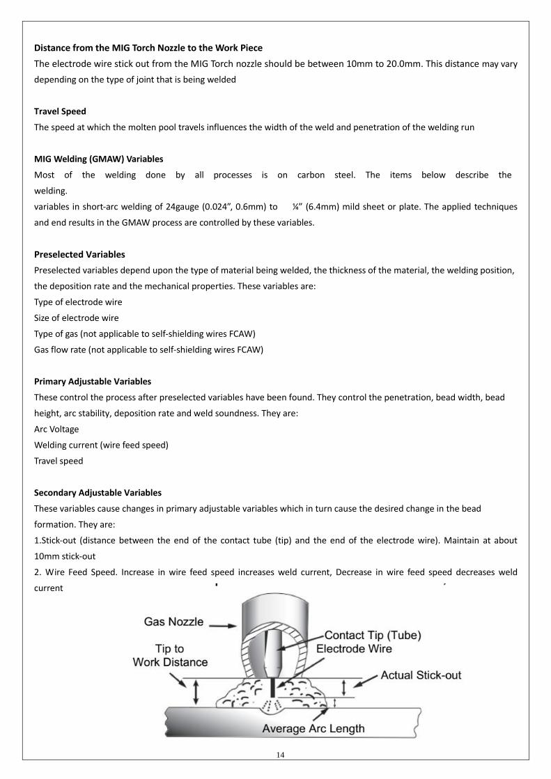
Distance from the MIG Torch Nozzle to the Work Piece
The electrode wire stick out from the MIG Torch nozzle should be between 10mm to 20.0mm. This distance may vary
depending on the type of joint that is being welded
Travel Speed
The speed at which the molten pool travels influences the width of the weld and penetration of the welding run
MIG Welding (GMAW) Variables
Most of the welding done by all processes is on carbon steel. The items below describe the
welding.
variables in short-arc welding of 24gauge (0.024”, 0.6mm) to ¼ ” (6.4mm) mild sheet or plate. The applied techniques
and end results in the GMAW process are controlled by these variables.
Preselected Variables
Preselected variables depend upon the type of material being welded, the thickness of the material, the welding position,
the deposition rate and the mechanical properties. These variables are:
Type of electrode wire
Size of electrode wire
Type of gas (not applicable to self-shielding wires FCAW)
Gas flow rate (not applicable to self-shielding wires FCAW)
Primary Adjustable Variables
These control the process after preselected variables have been found. They control the penetration, bead width, bead
height, arc stability, deposition rate and weld soundness. They are:
Arc Voltage
Welding current (wire feed speed)
Travel speed
Secondary Adjustable Variables
These variables cause changes in primary adjustable variables which in turn cause the desired change in the bead
formation. They are:
1.Stick-out (distance between the end of the contact tube (tip) and the end of the electrode wire). Maintain at about
10mm stick-out
2. Wire Feed Speed. Increase in wire feed speed increases weld current, Decrease in wire feed speed decreases weld
current

15
3. Nozzle Angle. This refers to the position of the welding gun in relation to the joint. The transverse angle is usually one half the included angle between plates forming the joint. The longitudinal angle is the angle between the centre line of the welding gun and a line perpendicular to the axis of the weld. The longitudinal angle is generally called the Nozzle Angle and can be either trailing (pulling) or leading (pushing). Whether the operator is left handed or right handed has to be considered to realize the effects of each angle in relation to the direction of travel.
Establishing the Arc and Making Weld Beads
Before attempting to weld on a finished piece of work, it is recommended that practice welds be made on a sample
metal of the same material as that of the finished piece
The easiest welding procedure for the beginner to experiment with MIG welding is the flat position. The equipment is
capable of flat, vertical and overhead positions.
For practicing MIG welding, secure some pieces of 16 or 18 gauge (0.06” 1.5mm or 0.08” 2.0mm) mild steel plate 6” x 6”
(150 x 150mm). Use 0.030” (0.8mm) flux cored gasless wire or a solid wire with shielding gas
Setting of the Power Source
Power source and Wirefeeder setting requires some practice by the operator, as the welding plant has two control settings
that have to balance. These are the Wirespeed control and the welding Voltage Control. The welding current is
determined by the Wirespeed control, the current will increase with increase Wirespeed, resulting in a shorter
arc. Less wire speed will reduce the current and lengthen the Increasing the welding voltage hardly
alters the current level, but lengthens the arc. By decreasing voltage, a shorter arc is obtained with a little
change in current level.
When changing to a different electrode wire diameter, different control settings are required. A
thinner electrode wire needs more Wirespeed to achieve the same current level
A satisfactory weld cannot be obtained if the Wirespeed and Voltage settings are not adjusted to suit the electrode wire
diameter and the dimensions of the work piece.
If the Wirespeed is too high for the welding voltage, “stubbing” will occur as the wire dips into the molten pool and does
not melt. Welding in these conditions normally produces a poor weld due to lack of fusion. If, however, the welding
voltage is too high, large drops will form on the end of the wire, causing spatter. The correct setting of voltage and

16
Wirespeed can be seen in the shape of the weld deposit and heard by a smooth regular arc sound. Refer to the Weld
Guide located on the inside of the wirefeed compartment door for setup information.
Electrode Wire Size Selection
The choice of Electrode wire size and shielding gas used depends on the following
Thickness of the metal to be welded
Capacity of the wire feed unit and Power Source
The amount of penetration required
The deposition rate required
The bead profile desired
The position of welding
Cost of the wire
7.Range of welding current and voltage in CO2 welding
-The option of the welding speed
The welding quality and productivity should be taken into consideration for the option of welding speed. In case that the
welding speed increases, it weakens the protection efficiency and speeds up the cooling process. As a consequence, it is
not optimal for the seaming. In the event that the speed is too slow, the work piece will be easily damaged, and the
seaming is not ideal. In practical operation, the welding speed should not exceed 1m/min.
-The length of wire stretching out
The length of wire stretching out the nozzle should be appropriate. The increase of the length of wire stretching out of the
nozzle can improve the productivity, but if it is too long, excessive spatter will occur in the welding process. Generally, the
length of wire stretching out the nozzle should be 10 times as the welding wire diameter.
-The setting of the C02 flow volume
The protection efficiency is the primary consideration. Besides, inner-angle welding has better protection efficiency than
external-angel welding. For the main parameter, refer to the following figure.
Option of C02 flow volume
Welding mode Thin wire C02 welding Thick wire C02 welding Thick wire, big current
C02 welding
C02(L/min) 5~15 15~25 25~50
Wireφ(mm) Short circuit transition Granular transition
Current(A) Voltage (V) Current(A) Voltage (V)
0.6 40~70 17~19 160~400 25~38
0.8 60~100 18~19 200~500 26~40
1.0 80~120 18~21 200~600 27~40

17
8.WELDING PARAMETERS TABLE
The option of the welding current and welding voltage directly influences the welding stability, welding quality and
productivity. In order to obtain the good welding quality, the welding current and welding voltage should be set optimally.
Generally, the setting of weld condition should be according to the welding diameter and the melting form as well as the
production requirement.
The following parameter is available for reference.
Parameter for butt-welding (Please refer to the following figure.)
Parameter for flat fillet welding (Please refer to the following figure.)
Plate thickness T (mm)
Gap g(mm)
Wire φ(mm)
Welding current (A)
Welding voltage (V)
Welding speed (cm/min)
Gas volume (L/min)
1.0 2.5~3.0 0.8~0.9 70~80 17~18 50~60 10~15
1.2 2.5~3.0 1.0 70~100 18~19 50~60 10~15
1.6 2.5~3.0 1.0 ~ 1.2 90~120 18~20 50~60 10~15
2.0 3.0~3.5 1.0 ~ 1.2 100~130 19~20 50~60 10~20
2.3 2.5~3.0 1.0 ~ 1.2 120~140 19~21 50~60 10~20
3.2 3.0~4.0 1.0 ~ 1.2 130~170 19~21 45~55 10~20
4.5 4.0~4.5 1.2 190~230 22~24 45~55 10~20
Plate thickness T (mm)
Gap g(mm)
Wire φ(mm)
Welding current (A)
Welding voltage (V)
Welding speed (cm/min)
Gas volume (L/min)
0.8 0 0.8~0.9 60~70 16~16.5 50~60 10
1.0 0 0.8~0.9 75~85 17~17.5 50~60 10~15
1.2 0 1.0 70~80 17~18 45~55 10
1.6 0 1.0 80~100 18~19 45~55 10~15
2.0 0~0.5 1.0 100~110 19~20 40~55 10~15
2.3 0.5~1.0 1.0 or 1.2 110~130 19~20 50~55 10~15
3.2 1.0~1.2 1.0 or 1.2 130~150 19~21 40~50 10~15
4.5 1.2~1.5 1.2 150~170 21~23 40~50 10~15

18
Parameter for fillet welding in the vertical position (Please refer to the following figure.)
Parameter for Lap Welding (Please refer to the following figure.)
Plate thickness T (mm)
Gap g(mm)
Wire φ(mm)
Welding current (A)
Welding voltage (V)
Welding speed (cm/min)
Gas volume (L/min)
0.8 A 0.8~0.9 60~70 16~17 40~45 10~15
1.2 A 1.0 80~100 18~19 45~55 10~15
1.6 A 1.0 ~ 1.2 100~120 18~20 45~55 10~15
2.0 A or B 1.0 ~ 1.2 100~130 18~20 45~55 15~20
2.3 B 1.0 ~ 1.2 120~140 19~21 45~50 15~20
3.2 B 1.0 ~ 1.2 130~160 19~22 45~50 15~20
4.5 B 1.2 150~200 21~24 40~45 15~20
Plate thickness T (mm)
Gap g(mm)
Wire φ(mm)
Welding current (A)
Welding voltage (V)
Welding speed (cm/min)
Gas volume (L/min)
1.2 2.5~3.0 1.0 70~100 18~19 50~60 10~15
1.6 2.5~3.0 1.0 ~ 1.2 90~120 18~20 50~60 10~15
2.0 3.0~3.5 1.0 ~ 1.2 100~130 19~20 50~60 10~20
2.3 3.0~3.5 1.0 ~ 1.2 120~140 19~21 50~60 10~20
3.2 3.0~4.0 1.0 ~ 1.2 130~170 22~22 45~55 10~20
4.5 4.0~4.5 1.2 200~250 23~26 45~55 10~20

19
9.CAUTION
1. Working environment
⑴ Welding should be carried out in a relatively dry environment with its humidity of 90% or less.
⑵ The temperature of the working environment should be within -10C to 40C.
⑶ Avoid welding in the open air unless sheltered from sunlight and rain, and never let rain or water infiltrate the machine.
⑷ Avoid welding in dusty area or environment with corrosive chemical gas.
⑸ Avoid gas shielded arc welding in environment with strong airflow.
2. Safety tips
Over-current/overheating protection circuit is installed in this welding machine. If the output current is too high or
overheating generated inside this welding machine, this welding machine will stop automatically. However, inappropriate
use will still lead to machine damage, so please note:
1. Ventilation
High current passes when welding is carried out, thus natural ventilation cannot satisfy the welding machine’s
cooling requirement. Maintain good ventilation of the louvers of this welding machine. The minimum distance
between this welding machine and any other objects in or near the working area should be 30cm. Good ventilation
is of critical importance for the normal performance and service life of this welding machine.
2. No over-current.
Remember to observe the max load current at any moment (refer to the optioned duty cycle). Make sure that the
welding current should not exceed the max load current.
If welding is carried out under a current which is higher than the max current, over-current protection will occur; the
output voltage of the welding machine will be not stable; arc interruption will occur. In this case, please lower the
current.
3. No over-load.
Over-load current could obviously shorten the welding equipment’s life, or even damage the machine.
A sudden halt may occur while the welding operation is carried out while this welding machine is of over-load status.
Under this circumstance, it is unnecessary to restart this welding machine. Keep the built-in fan working to bring
down the temperature inside the welding machine.
4. Avoid electric shock.
An earth terminal is available for this welding equipment. Connect it with the earth cable to avoid the static and
electric shock.

20
10. MAINTENANCE
1. Disconnect input plug or power before maintenance or repair on
machine.
2. Be sure input ground wire is properly connect to a ground
terminal.
3. Check whether the inner gas-electricity connection is well (esp.
the plugs), and tighten the loose connection; if there is
oxidization, remove it with sand paper and then re-connect.
4. Keep hands, hair, loose clothing, and tools away from electrical
parts such as fans, wires when the machine is switched on.
5. Clear the dust at regular intervals with clean and dry compressed
air; if the working condition is with heavy smoke and air pollution,
the welding machine should be cleaned daily.
6. The compressed air should be reduced to the required pressure
lest the little parts in the welding machine be damaged.
7. To avoid water and rain, if there is, dry it in time, and check the
insulation with mega-meter (including that between the
connection and that between the case and the connection). Only
when there is no abnormal phenomenon should the welding
continue.
8. If the machine is not used for a long time, put it into the original
packing in dry condition.

21
11. DAILY CHECKING
To make best use of the machine, daily checking is very important. During the daily checking, please check in the order of
torch, wire-feeding vehicle, all kinds of PCB, the gas hole, and so on. Remove the dust or replace some parts if necessary.
To maintain the purity of the machine, please use original welding parts.
Cautions:Only the qualified technicians are authorized to undertake the repair and check task of this welding equipment
in case of machine fault.
11.1. Power supply
Part Check Remarks
Control panel 1. Operation, replacement and installation of Switch.
2. Switch on the power, and check if the power indicator is on.
Fan 1. Check if the fan is functioning and the sound generated is
normal.
If the fan doesn’t work or the
sound is abnormal, do inner check.
Power supply
1. Switch on the power supply, and check if abnormal vibration,
heating of the case of this equipment, variation of colors of case
or buzz presents.
Other parts 1. Check if gas connection is available, case and other joints are
in good connection.
11.2. Welding torch
Part Check Remarks
Nozzle
1. Check if the nozzle is fixed firmly and
distortion of the tip exists. Possible gas leakage occurs due to the unfixed nozzle.
2. Check if there is spatter sticking on
the nozzle.
Spatter possibly leads to the damage of torch. Use
anti-spatter to eliminate the spatter.
Contact tip
1. Check if the contact tip is fixed
firmly. Unfixed contract tip possibly leads to unstable arc.
2. Check if the contact tip is physically
complete.
The physically incomplete contact tip possibly leads to
unstable arc and arc automatically terminating.
Wire feeding
hose
1. Make sure that there is the
agreement of wire and wire feed
tube.
Disagreement of the diameters of wire and wire feed tube
possibly leads to the unstable arc. Replace it/them if
necessary.
2. Make sure that there is no bending
or elongation of wire feed tube.
Bending and elongation of wire feed tube possibly leads to
the unstable wire feed and arc. Replace it if necessary.
3. Make sure that there is no dust or
spatter accumulated inside the wire
feed tube, which makes the wire
feed tub blocked.
If there is dust or spatter, remove it.
4. Check if the wire feed tube and
O-shaped seal ring are physically
complete.
The Physically incomplete wire feed tube or O-shaped seal
ring possibly leads to the excessive spatter. Replace the
wire feed tube or O-shaped seal ring if necessary.
Part Check Remarks
Diffuser
1. Make sure that the diffuser of
required specification is installed
and is unblocked.
Defection weld or even the damage of torch occurs due to
the non-installation of diffuser or the unqualified diffuser.

22
11.3. Wire feeder
Part Check Remarks
Pressure
adjusting handle
1. Check if the pressure-adjusting handle is
fixed and adjusted to the desired position.
The unfixed pressure-adjusting handle leads
to the unstable welding output.
Wire-feeding
hose
1. Check if there is dust or spatter inside the
hose or beside wire-feeding wheel. Remove the dust.
2. Check if there is a diameter agreement of
wire and wire-feeding hose.
Non-agreement of the diameter of wire and
wire-feeding hose possibly leads to the
excessive spatter and unstable arc.
3. Check if rod and wire feeding groove are
concentric. Unstable arc possibly occurs.
Wire-feeding
wheel
1. Check if there is an agreement of wire
diameter and wire-feeding wheel.
Non-agreement of wire diameter and
wire-feeding wheel possibly leads to the
excessive spatter and unstable arc.
2. Check if the wire groove is blocked. Replace it if necessary.
Pressure
adjusting wheel
1. Check if the pressure adjusting wheel can
rotate smoothly, and it’s physically
complete.
Unstable rotation or physically
incompleteness of the wheel possibly leads to
unstable wire feeding and arc.
11.4. Cables
Part Check Remarks
Torch
cable
1. Check if the cable of torch is twisted. The twisted torch cable leads to unstable wire
feeding and arc. 2. Check if the coupling plug is in loose connection.
Output
cable
1. Check if the cable is physically complete. Relevant measures should be taken to obtain
stable weld and prevent the possible electric
shock. 2. Check if insulation damage or loose connection
exists.
Input
cable
1. Check if the cable is physically complete.
2. Check if insulation damage or loose connection
exists.
Earth
cable
1. Check if the earth cables are well fixed and not
short-circuited. Relevant measures should be taken to prevent
the possible electric shock. 2. Check if this welding equipment is well grounded.

23
12.CONNECTION DIAGRAM OF THE MACHINE

24
13.EXPLOSION DRAWING
NO NAME NO NAME
1 Euro type MIG torch socket 18 rear panel
2 front panel 19 solenoid valve
3 input quick connector 20 power switch
4 control PCB 21 fan
5 aviation socket 22 radiator 2
6 output quick connector 23 base panel
7 front plastic cover 24 radiator 3
8 radiator 1 25 metal stand 1
9 rectifier tube 26 support parts
10 handle 27 metal stand 2
11 rectifier bridge 28 clapboard
12 IGBT 29 wire spool
13 main PCB 30 wire spool holder
14 casing 31 wire feeder
15 rear plastic cover 32 side plate
16 fan fixer 33 lock
17 wire clip