HF meander-line antenna simulations for NVIS on a HMMW … · Microsoft Word - HF meander-line...
18
HF meanderline antenna simulations and investigations for NVIS on a HMMV Chad M. Gardner SPAWAR 7100 Applied Research and Development Phone: 8432182270 (U) [email protected] (S) [email protected] Introduction Meanderline antennas (MLA) have been in use for many applications, ranging from Radio Frequency Identification (RFID) to WLAN communication systems [1] [3]. Typical planar meanderline antennas are designed to electrically lengthen the antenna and thereby allowing a lower frequency of operation [4]. In [4] the author discusses in chapter 7 many different configurations and designs for the design of a MLA. The designs in [4] were primarily at Ultra High Frequencies (UHF) for mobile phone antennas. The researcher in [5] designed and simulated a High Frequency (HF) MLA at 28 MHz. However, for NearVertical Incident Skywave (NVIS) propagation, frequencies between 1.815 MHz are typically used [6]. The authors in [6] – [7] discuss a good overview on NVIS and its beneficial communication coverage within 300 km. Researchers from the late 1990s tried to improve NVIS from landbased vehicles by using different techniques then traditional tilted monopole/whip designs. The authors in [6]–[8] did an extensive study on using characteristic mode excitation using a HF loop antenna. In addition, the authors in [6] – [8] studied the reduction in efficiency of NVIS propagation with currently fielded tilted whip antennas on a Land Rover vehicle. The paper in [7] discussed how the optimum position for a titled whip was the configuration in which the antenna was pointed away from the vehicle. Unfortunately, most tactical scenarios would have the antenna tilted toward the front of the vehicle. As the authors in [7] discuss, when the antenna is tilted towards the front of the vehicle, a substantial reduction in efficiency for NVIS propagation occurs. From researched literature, an insitu antenna design of a MLA incorporated in the roof of a High Mobility Motor Vehicle (HMMV) hasn’t been considered. An insitu design may have not been considered due inability of antenna designers to get the proper models of vehicles for simulating. For many antenna designers High Frequency Structural Simulator (HFSS) can simulate and provide Z parameters and gain patterns of incorporated radiators and was used in this study.
Transcript of HF meander-line antenna simulations for NVIS on a HMMW … · Microsoft Word - HF meander-line...
HF meander-‐line antenna simulations and investigations for NVIS on a HMMV
Chad M. Gardner
SPAWAR 7100 Applied Research and Development
Phone: 843-‐218-‐2270 (U) [email protected]
(S) [email protected] Introduction Meander-‐line antennas (MLA) have been in use for many applications, ranging from Radio Frequency Identification (RFID) to WLAN communication systems [1]-‐ [3]. Typical planar meander-‐line antennas are designed to electrically lengthen the antenna and thereby allowing a lower frequency of operation [4]. In [4] the author discusses in chapter 7 many different configurations and designs for the design of a MLA. The designs in [4] were primarily at Ultra High Frequencies (UHF) for mobile phone antennas. The researcher in [5] designed and simulated a High Frequency (HF) MLA at 28 MHz. However, for Near-‐Vertical Incident Skywave (NVIS) propagation, frequencies between 1.8-‐15 MHz are typically used [6]. The authors in [6] – [7] discuss a good overview on NVIS and its beneficial communication coverage within 300 km. Researchers from the late 1990s tried to improve NVIS from land-‐based vehicles by using different techniques then traditional tilted monopole/whip designs. The authors in [6]–[8] did an extensive study on using characteristic mode excitation using a HF loop antenna. In addition, the authors in [6] – [8] studied the reduction in efficiency of NVIS propagation with currently fielded tilted whip antennas on a Land Rover vehicle. The paper in [7] discussed how the optimum position for a titled whip was the configuration in which the antenna was pointed away from the vehicle. Unfortunately, most tactical scenarios would have the antenna tilted toward the front of the vehicle. As the authors in [7] discuss, when the antenna is tilted towards the front of the vehicle, a substantial reduction in efficiency for NVIS propagation occurs. From researched literature, an in-‐situ antenna design of a MLA incorporated in the roof of a High Mobility Motor Vehicle (HMMV) hasn’t been considered. An in-‐situ design may have not been considered due inability of antenna designers to get the proper models of vehicles for simulating. For many antenna designers High Frequency Structural Simulator (HFSS) can simulate and provide Z-‐parameters and gain patterns of incorporated radiators and was used in this study.
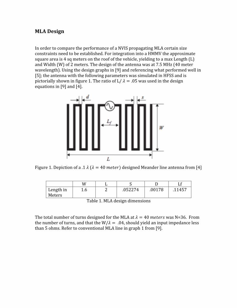
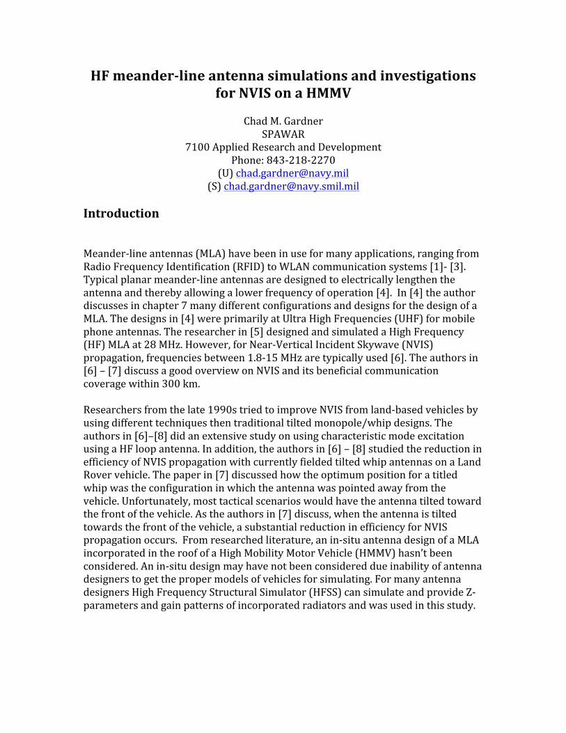
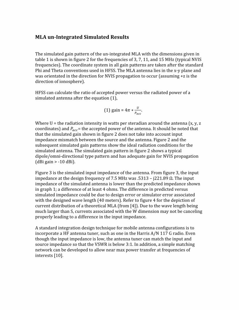
MLA Design In order to compare the performance of a NVIS propagating MLA certain size constraints need to be established. For integration into a HMMV the approximate square area is 4 sq meters on the roof of the vehicle, yielding to a max Length (L) and Width (W) of 2 meters. The design of the antenna was at 7.5 MHz (40 meter wavelength). Using the design graphs in [9] and referencing what performed well in [5]; the antenna with the following parameters was simulated in HFSS and is pictorially shown in figure 1. The ratio of L/ 𝜆 = .05 was used in the design equations in [9] and [4].
Figure 1. Depiction of a .1 𝜆 (𝜆 = 40 𝑚𝑒𝑡𝑒𝑟) designed Meander line antenna from [4]
W L S D Lf Length in Meters
1.6 2 .052274 .00178 .11457
Table 1. MLA design dimensions The total number of turns designed for the MLA at 𝜆 = 40 𝑚𝑒𝑡𝑒𝑟𝑠 was N=36. From the number of turns, and that the W/𝜆 = .04, should yield an input impedance less than 5 ohms. Refer to conventional MLA line in graph 1 from [9].
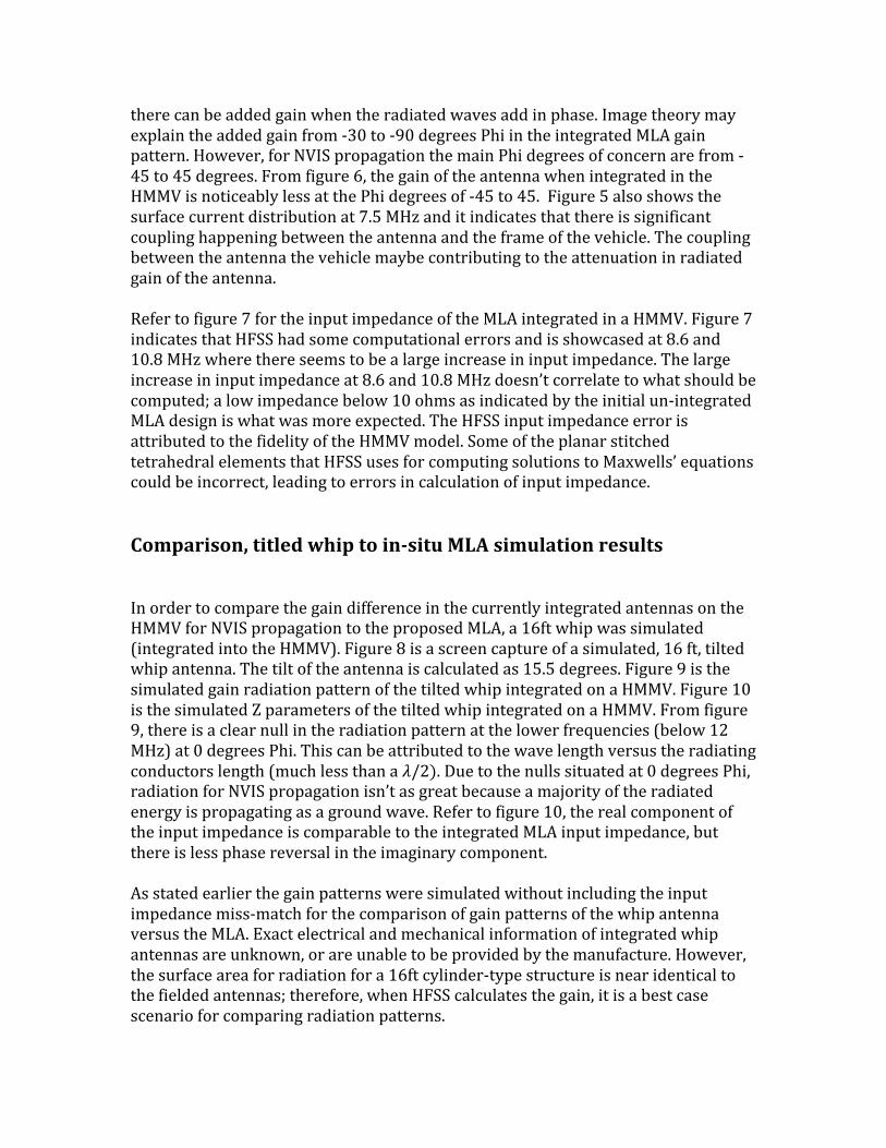
MLA un-‐Integrated Simulated Results The simulated gain pattern of the un-‐integrated MLA with the dimensions given in table 1 is shown in figure 2 for the frequencies of 3, 7, 11, and 15 MHz (typical NVIS frequencies). The coordinate system in all gain patterns are taken after the standard Phi and Theta conventions used in HFSS. The MLA antenna lies in the x-‐y plane and was orientated in the direction for NVIS propagation to occur (assuming +z is the direction of ionosphere). HFSS can calculate the ratio of accepted power versus the radiated power of a simulated antenna after the equation (1),
(1) gain = 4𝜋 ∗ !!!""
.
Where U = the radiation intensity in watts per steradian around the antenna (x, y, z coordinates) and 𝑃!""= the accepted power of the antenna. It should be noted that that the simulated gain shown in figure 2 does not take into account input impedance mismatch between the source and the antenna. Figure 2 and the subsequent simulated gain patterns show the ideal radiation conditions for the simulated antenna. The simulated gain pattern in figure 2 shows a typical dipole/omni-‐directional type pattern and has adequate gain for NVIS propagation (dBi gain > -‐10 dBi). Figure 3 is the simulated input impedance of the antenna. From figure 3, the input impedance at the design frequency of 7.5 MHz was .5313 – j221.89 Ω. The input impedance of the simulated antenna is lower than the predicted impedance shown in graph 1; a difference of at least 4 ohms. The difference in predicted versus simulated impedance could be due to design error or simulator error associated with the designed wave length (40 meters). Refer to figure 4 for the depiction of current distribution of a theoretical MLA (from [4]). Due to the wave length being much larger than S, currents associated with the W dimension may not be canceling properly leading to a difference in the input impedance. A standard integration design technique for mobile antenna configurations is to incorporate a HF antenna tuner, such as one in the Harris A/N 117 G radio. Even though the input impedance is low, the antenna tuner can match the input and source impedance so that the VSWR is below 3:1. In addition, a simple matching network can be developed to allow near max power transfer at frequencies of interests [10].
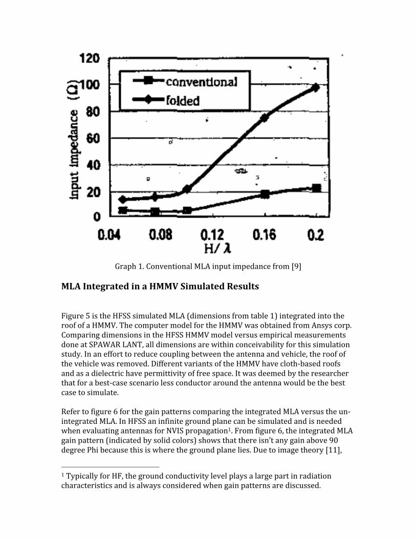
Graph 1. Conventional MLA input impedance from [9]
MLA Integrated in a HMMV Simulated Results Figure 5 is the HFSS simulated MLA (dimensions from table 1) integrated into the roof of a HMMV. The computer model for the HMMV was obtained from Ansys corp. Comparing dimensions in the HFSS HMMV model versus empirical measurements done at SPAWAR LANT, all dimensions are within conceivability for this simulation study. In an effort to reduce coupling between the antenna and vehicle, the roof of the vehicle was removed. Different variants of the HMMV have cloth-‐based roofs and as a dielectric have permittivity of free space. It was deemed by the researcher that for a best-‐case scenario less conductor around the antenna would be the best case to simulate. Refer to figure 6 for the gain patterns comparing the integrated MLA versus the un-‐integrated MLA. In HFSS an infinite ground plane can be simulated and is needed when evaluating antennas for NVIS propagation1. From figure 6, the integrated MLA gain pattern (indicated by solid colors) shows that there isn’t any gain above 90 degree Phi because this is where the ground plane lies. Due to image theory [11],
1 Typically for HF, the ground conductivity level plays a large part in radiation characteristics and is always considered when gain patterns are discussed.
there can be added gain when the radiated waves add in phase. Image theory may explain the added gain from -‐30 to -‐90 degrees Phi in the integrated MLA gain pattern. However, for NVIS propagation the main Phi degrees of concern are from -‐45 to 45 degrees. From figure 6, the gain of the antenna when integrated in the HMMV is noticeably less at the Phi degrees of -‐45 to 45. Figure 5 also shows the surface current distribution at 7.5 MHz and it indicates that there is significant coupling happening between the antenna and the frame of the vehicle. The coupling between the antenna the vehicle maybe contributing to the attenuation in radiated gain of the antenna. Refer to figure 7 for the input impedance of the MLA integrated in a HMMV. Figure 7 indicates that HFSS had some computational errors and is showcased at 8.6 and 10.8 MHz where there seems to be a large increase in input impedance. The large increase in input impedance at 8.6 and 10.8 MHz doesn’t correlate to what should be computed; a low impedance below 10 ohms as indicated by the initial un-‐integrated MLA design is what was more expected. The HFSS input impedance error is attributed to the fidelity of the HMMV model. Some of the planar stitched tetrahedral elements that HFSS uses for computing solutions to Maxwells’ equations could be incorrect, leading to errors in calculation of input impedance. Comparison, titled whip to in-‐situ MLA simulation results In order to compare the gain difference in the currently integrated antennas on the HMMV for NVIS propagation to the proposed MLA, a 16ft whip was simulated (integrated into the HMMV). Figure 8 is a screen capture of a simulated, 16 ft, tilted whip antenna. The tilt of the antenna is calculated as 15.5 degrees. Figure 9 is the simulated gain radiation pattern of the tilted whip integrated on a HMMV. Figure 10 is the simulated Z parameters of the tilted whip integrated on a HMMV. From figure 9, there is a clear null in the radiation pattern at the lower frequencies (below 12 MHz) at 0 degrees Phi. This can be attributed to the wave length versus the radiating conductors length (much less than a 𝜆/2). Due to the nulls situated at 0 degrees Phi, radiation for NVIS propagation isn’t as great because a majority of the radiated energy is propagating as a ground wave. Refer to figure 10, the real component of the input impedance is comparable to the integrated MLA input impedance, but there is less phase reversal in the imaginary component. As stated earlier the gain patterns were simulated without including the input impedance miss-‐match for the comparison of gain patterns of the whip antenna versus the MLA. Exact electrical and mechanical information of integrated whip antennas are unknown, or are unable to be provided by the manufacture. However, the surface area for radiation for a 16ft cylinder-‐type structure is near identical to the fielded antennas; therefore, when HFSS calculates the gain, it is a best case scenario for comparing radiation patterns.

Figure 11 is the gain patterns for both the simulated tilted whip and integrated MLA. In comparing the gain patterns, it is clear that between -‐15 and 15 degrees Phi the MLA is a better NVIS radiator than the whip antenna. However, at the other Phi degrees of interests for NVIS propagation the whip antenna performs better, especially at frequencies below 7 MHz. High Impedance surfaces (HIS) As a way to improve the gain and reduce coupling between the vehicle and the antenna, HIS were investigated. An electromagnetic structure having a HIS was introduced in 1999 by Sievenpiper and became known as the “mushroom” [12]. The geometry of the mushroom structure is analogous to a corrugated metal surface in which the corrugations have been folded up into lumped-‐circuit elements and distributed in a two-‐dimensional lattice. The height of such a structure is lower than a one-‐quarter wavelength and the distance between neighboring cells (periodicity) is much less than one wavelength. Being that the periodicity is much less than a wavelength, this has potential to be material that the printed HF antenna could lay on. Instead of the typical .25 𝜆 reduction in distance away from a perfect electric conductor (PEC), a typical sievenpiper element is .055 𝜆 [13]. Unfortunately, using the design of 𝜆 = 40 meters, the distance away would still be 2.2 meters. A 2.2 meter distance from a reflector e.g. the roof of the HMMV, would be too impractical for integration of a MLA. Conclusion Simulations of a HF MLA for NVIS propagation were conducted in HFSS. Gain patterns and input impedance were simulated in both un-‐integrated and integrated scenarios. Further, the integrated MLA in a HMVV was compared with a 16 ft tilted whip antenna. In comparing the integrated versus un-‐integrated MLA, there is at most a 9.5 reduction in gain (lower NVIS frequency 3 MHz) and at least 1.5 reduction in gain (higher NVIS frequency 15 MHz) at the Phi NVIS degrees of interests. In comparing the tilted whip antenna gain pattern with integrated MLA, the MLA is a better NVIS radiator than the whip antenna between -‐15 and 15 degrees Phi. However, at the other Phi degrees of interests for NVIS propagation the whip antenna performs better, especially at frequencies below 7 MHz. Input impedance for the simulated MLA was especially low (below 5 ohms). Due to the impedance being low, there would be definite and distinct attenuation attributed to the matching network or antenna tuner. HIS were researched as a possible way to reduce coupling between the vehicle and the antenna. HIS were found to be un-‐usable due to the distance away from the vehicle, 2.2 meters.

Future Work Reducing the coupling between the radiating elements of an incorporated antenna into the vehicle would prove the most beneficial in achieving better radiation characteristics along with higher input impedance. In addition, further refinement of in-‐situ placement of the antenna should be considered in future simulations.
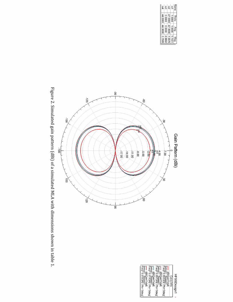
Figure 2. Simulated gain pattern (dBi) of a sim
ulated MLA w
ith dimensions show
n in table 1.
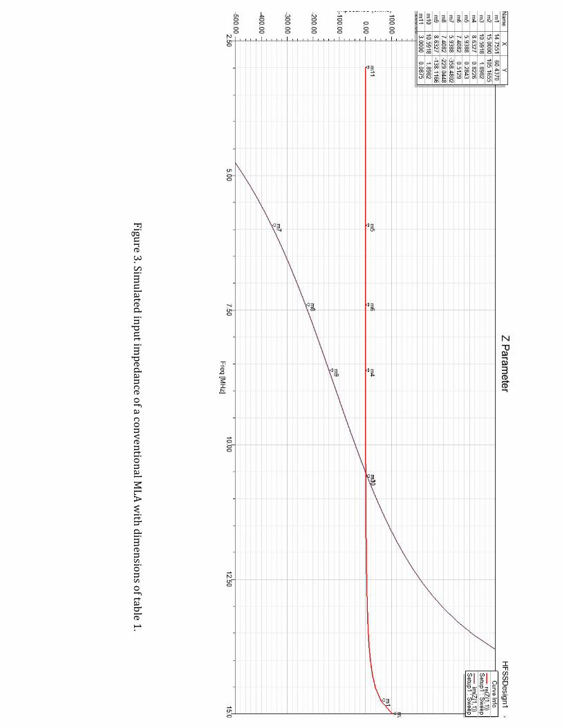
Figure 3. Simulated input im
pedance of a conventional MLA w
ith dimensions of table 1.
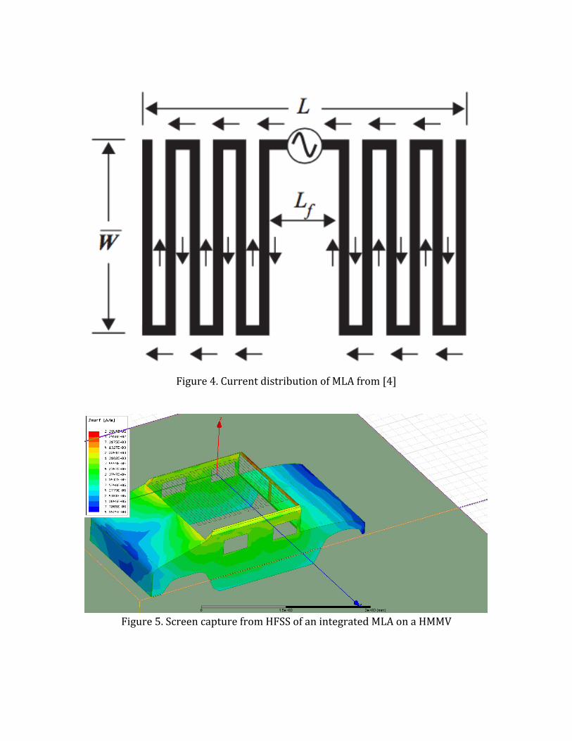
Figure 4. Current distribution of MLA from [4]
Figure 5. Screen capture from HFSS of an integrated MLA on a HMMV
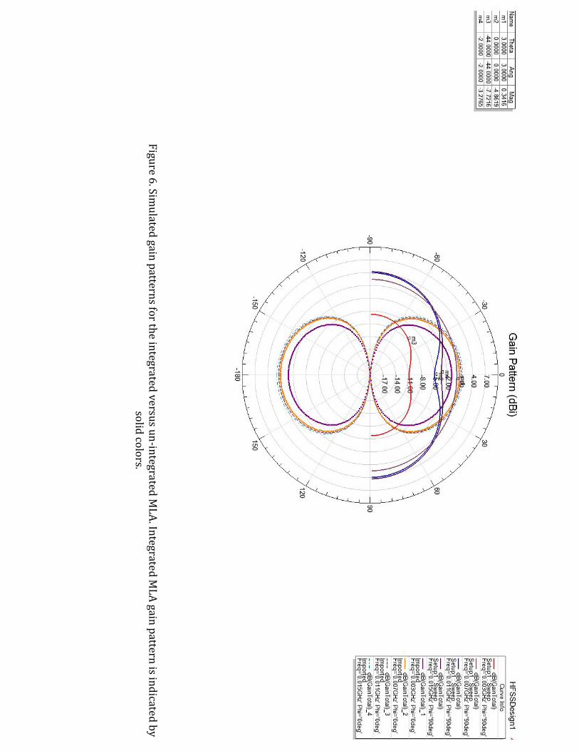
Figure 6. Simulated gain patterns for the integrated versus un-‐integrated M
LA. Integrated MLA gain pattern is indicated by
solid colors.
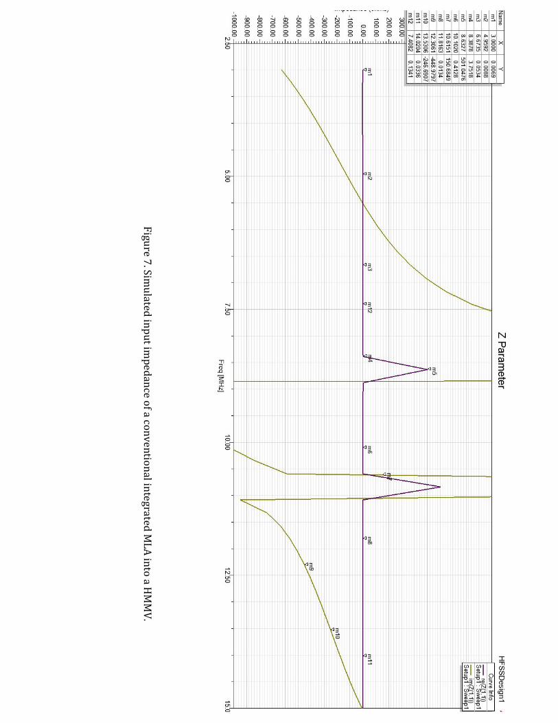
Figure 7. Simulated input im
pedance of a conventional integrated MLA into a H
MMV.
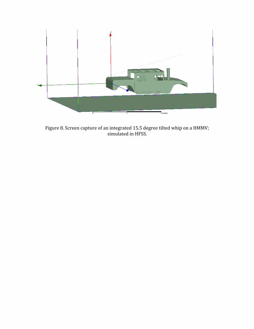
Figure 8. Screen capture of an integrated 15.5 degree tilted whip on a HMMV; simulated in HFSS.
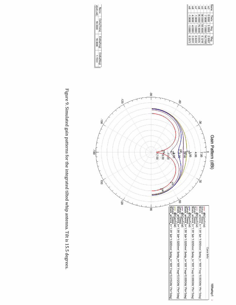
Figure 9. Simulated gain patterns for the integrated tilted w
hip antenna. Tilt is 15.5 degrees.
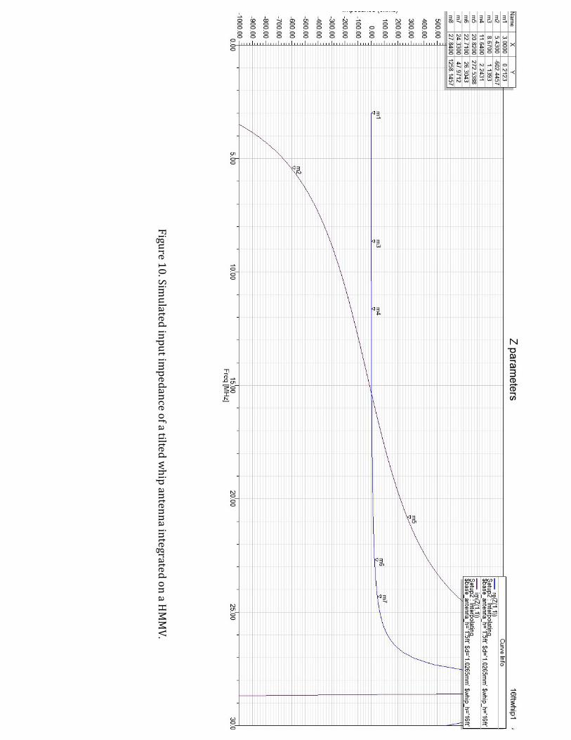
Figure 10. Simulated input im
pedance of a tilted whip antenna integrated on a H
MMV.
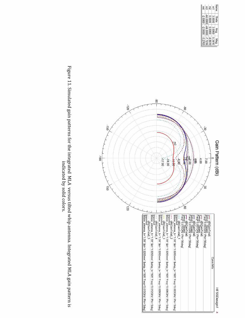
Figure 11. Simulated gain patterns for the integrated M
LA versus tilted whip antenna. Integrated M
LA gain pattern is indicated by solid colors.

Bibliography [1] F. Paredes, G. Zamora, F. J. Herraiz-‐Martinez, F. Martin and J. Bonache, "Dual-‐Band UHF-‐RFID Tags Based on Meander-‐Line Antennas Loaded With Spiral Resonators," in IEEE Antennas and Wireless Propagation Letters, vol. 10, no. , pp. 768-‐771, 2011. [2] S. H. Lee, K. J. Kim, J. H. Jung, Y. J. Yoon and B. N. Kim, "Meander line loop antenna with coupled feed for multiband mobile phone," Antenna Technology (iWAT), 2011 International Workshop on, Hong Kong, 2011, pp. 194-‐197. [3]C. C. Lin, S. W. Kuo and H. R. Chuang, "A 2.4-‐GHz printed meander-‐line antenna for USB WLAN with notebook-‐PC housing," in IEEE Microwave and Wireless Components Letters, vol. 15, no. 9, pp. 546-‐548, Sept. 2005. [4] Fujimoto, K. and Morishita, H. (2014) Modern Small Antennas [5] P. J. Kajenski, "HF meandered line dipoles optimized with simulated annealing," 2005 IEEE Antennas and Propagation Society International Symposium, 2005, pp. 287-‐290 vol. 2B. [6] B. A. Austin and K. P. Murray, "The application of characteristic-‐mode techniques to vehicle-‐mounted NVIS antennas," in IEEE Antennas and Propagation Magazine, vol. 40, no. 1, pp. 7-‐21, 30, Feb 1998. [7] B.A. Austin and W.C. Liu "Assessment of vehicle-‐mounted antennas for NVIS applications" IEEE proceedings on Microwaves and Propagation Vol 149. No 3. June 2002 [8] Murray, K.P.; Austin, B.A., "Novel antenna configurations for vehicle-‐borne NVIS applications," Antennas and Propagation, 1995., Ninth International Conference on (Conf. Publ. No. 407) , vol., no., pp.415,418 vol.1, 4-‐7 Apr 1995 [9] M. Takiguchi and Y. Yamada, "Input impedance increase of a very small meander line antenna," Antennas and Propagation Society International Symposium, 2003. IEEE, Columbus, OH, USA, 2003, pp. 856-‐859 vol.1. [10] Bowick, C., (2011) RF Circuit Design [11] Harrington, Roger F. Time-‐harmonic Electromagnetic Fields. McGraw-‐Hill, 1961. [12] D. Sievenpiper, R. Broas and E. Yablonovitch, "Antennas on high-‐impedance ground planes," Microwave Symposium Digest, 1999 IEEE MTT-‐S International, Anaheim, CA, USA, 1999, pp. 1245-‐1248 vol.3.

[13] ANSYS Corporation, “High Impedance Surfaces”, ANSYS Metamaterial Summit, Burlington, MA, USA, Sept 2012