Heterogeneous Cellular Networks - Webspace - The University of
11
IEEE Communications Magazine • June 2012 54 0163-6804/12/$25.00 © 2012 IEEE INTRODUCTION To address the explosive growth in data demands driven by smart phones, tablets, and other media-hungry devices, network operators will have to significantly increase the capacity of their networks as well as reduce the cost/bit delivered by perhaps two orders of magnitude. A number of studies have documented the over 100 percent annual growth in mobile data traffic which started around 2008, and is set to continue indefinitely, which projects a factor of 1000 increase from 2007–2016. Clearly, the typical cautious approaches to adding capacity are not up to this challenge. An important new development is the deployment of heterogeneous base stations underlaid in a traditional (macro) cellular net- work. In such a heterogeneous network, various classes of low power nodes (LPNs) are dis- tributed throughout the macro cell network. There are various types of LPNs including micro base stations (often called eNodeBs, or eNBs), pico eNBs, home eNBs (also called fem- tocells), relays and distributed antenna systems (DAS, also called remote radio heads or RRHs). In heterogeneous network (HetNet) deployments, the overlay macro cell provides a wide area coverage umbrella while the LPNs are deployed in a more targeted manner to alleviate coverage dead zones, and more impor- tantly, traffic hot zones. A HetNet topology fundamentally challenges many time-honored aspects of cellular system design and analysis. Two prominent examples of outdated modeling are • The use of a uniform hexagonal grid to model the base station locations • The assumption that a mobile should gener- ally connect to the base station providing the strongest signal, which in a HetNet is quite often not the one providing the best rate or network-wide performance The goal of this article is to provide an overview of a heterogeneous network design, and show that its co-existence with a macro- network from an air-interface and an infra- structure point of view is highly feasible. We focus on a two-tier macro-pico network and provide a primer on new state-of-the-art theo- retical analysis for HetNets as well as extensive detailed simulations. We show that the key trends predicted by both models and approach- es are in broad agreement. This article covers the following topics. A coverage analysis of multi-tier networks based on random spatial models is provided. We pro- vide simulated performance of a baseline hetero- geneous network with no inter-cell interference coordination (ICIC). A discussion of standard- ized ICIC techniques based on LTE Release-9 and 10 for a macro-pico scenario is given fol- ABSTRACT The proliferation of internet-connected mobile devices will continue to drive growth in data traffic in an exponential fashion, forcing network operators to dramatically increase the capacity of their networks. To do this cost-effec- tively, a paradigm shift in cellular network infra- structure deployment is occurring away from traditional (expensive) high-power tower-mount- ed base stations and towards heterogeneous ele- ments. Examples of heterogeneous elements include microcells, picocells, femtocells, and dis- tributed antenna systems (remote radio heads), which are distinguished by their transmit pow- ers/coverage areas, physical size, backhaul, and propagation characteristics. This shift presents many opportunities for capacity improvement, and many new challenges to co-existence and network management. This article discusses new theoretical models for understanding the hetero- geneous cellular networks of tomorrow, and the practical constraints and challenges that opera- tors must tackle in order for these networks to reach their potential. LTE-ADVANCED AND 4G WIRELESS COMMUNICATIONS: P ART 2 Amitabha Ghosh, Nitin Mangalvedhe, Rapeepat Ratasuk, Bishwarup Mondal, Mark Cudak, Eugene Visotsky, and Timothy A. Thomas, Nokia Siemens Networks Jeffrey G. Andrews, Ping Xia, Han Shin Jo, Harpreet S. Dhillon, and Thomas D. Novlan, The University of Texas at Austin Heterogeneous Cellular Networks: From Theory to Practice
Transcript of Heterogeneous Cellular Networks - Webspace - The University of

IEEE Communications Magazine • June 201254 0163-6804/12/$25.00 © 2012 IEEE
INTRODUCTION
To address the explosive growth in data demandsdriven by smart phones, tablets, and othermedia-hungry devices, network operators willhave to significantly increase the capacity oftheir networks as well as reduce the cost/bitdelivered by perhaps two orders of magnitude. Anumber of studies have documented the over100 percent annual growth in mobile data trafficwhich started around 2008, and is set to continueindefinitely, which projects a factor of 1000increase from 2007–2016. Clearly, the typicalcautious approaches to adding capacity are notup to this challenge.
An important new development is thedeployment of heterogeneous base stationsunderlaid in a traditional (macro) cellular net-
work. In such a heterogeneous network, variousclasses of low power nodes (LPNs) are dis-tributed throughout the macro cell network.There are various types of LPNs includingmicro base stations (often called eNodeBs, oreNBs), pico eNBs, home eNBs (also called fem-tocells), relays and distributed antenna systems(DAS, also called remote radio heads orRRHs). In heterogeneous network (HetNet)deployments, the overlay macro cell provides awide area coverage umbrella while the LPNsare deployed in a more targeted manner toalleviate coverage dead zones, and more impor-tantly, traffic hot zones.
A HetNet topology fundamentally challengesmany time-honored aspects of cellular systemdesign and analysis. Two prominent examples ofoutdated modeling are• The use of a uniform hexagonal grid to
model the base station locations• The assumption that a mobile should gener-
ally connect to the base station providingthe strongest signal, which in a HetNet isquite often not the one providing the bestrate or network-wide performance
The goal of this article is to provide anoverview of a heterogeneous network design,and show that its co-existence with a macro-network from an air-interface and an infra-structure point of view is highly feasible. Wefocus on a two-tier macro-pico network andprovide a primer on new state-of-the-art theo-retical analysis for HetNets as well as extensivedetailed simulations. We show that the keytrends predicted by both models and approach-es are in broad agreement.
This article covers the following topics. Acoverage analysis of multi-tier networks basedon random spatial models is provided. We pro-vide simulated performance of a baseline hetero-geneous network with no inter-cell interferencecoordination (ICIC). A discussion of standard-ized ICIC techniques based on LTE Release-9and 10 for a macro-pico scenario is given fol-
ABSTRACT
The proliferation of internet-connectedmobile devices will continue to drive growth indata traffic in an exponential fashion, forcingnetwork operators to dramatically increase thecapacity of their networks. To do this cost-effec-tively, a paradigm shift in cellular network infra-structure deployment is occurring away fromtraditional (expensive) high-power tower-mount-ed base stations and towards heterogeneous ele-ments. Examples of heterogeneous elementsinclude microcells, picocells, femtocells, and dis-tributed antenna systems (remote radio heads),which are distinguished by their transmit pow-ers/coverage areas, physical size, backhaul, andpropagation characteristics. This shift presentsmany opportunities for capacity improvement,and many new challenges to co-existence andnetwork management. This article discusses newtheoretical models for understanding the hetero-geneous cellular networks of tomorrow, and thepractical constraints and challenges that opera-tors must tackle in order for these networks toreach their potential.
LTE-ADVANCED AND 4G WIRELESSCOMMUNICATIONS: PART 2
Amitabha Ghosh, Nitin Mangalvedhe, Rapeepat Ratasuk, Bishwarup Mondal, Mark Cudak,
Eugene Visotsky, and Timothy A. Thomas, Nokia Siemens Networks
Jeffrey G. Andrews, Ping Xia, Han Shin Jo, Harpreet S. Dhillon, and Thomas D. Novlan,
The University of Texas at Austin
Heterogeneous Cellular Networks:From Theory to Practice
GHOSH LAYOUT_Layout 1 5/22/12 6:07 PM Page 54
IEEE Communications Magazine • June 2012 55
lowed by simulation results. The logistics ofdeploying heterogeneous elements are discussedincluding the installation, management, and pro-vision of backhaul for street level pico nodesalong with some basic HetNet Proof-of-Concept(PoC) results.
BASELINE COVERAGE ANDTHROUGHPUT ANALYSIS FOR
MULTI-TIER NETWORKS
Cellular modeling and analysis has not changedvery much in the last decade. Industry (and aca-demic) simulations typically rely on a hexagonalgrid model for the base station locations, andassume the user terminals (UEs) are uniformlyscattered and connect to the strongest base sta-tion signal. Dozens of system parameters can bemodeled and tuned in such simulations, and theresults have been sufficiently accurate as toenable the evaluation of new proposed tech-niques and guide field deployments. Mathemati-cal analysis by researchers has typically requiredeither ignoring other-cell interference (single cellmodels), treating it as having a fixed value(sometimes called the “Wyner” model), or mak-ing other major simplifications that make theconclusions from such endeavors questionable.Not surprisingly, theoretical researchers andindustry have wound up going in largely separatedirections as a result [1].
Moving to the HetNets of tomorrow, evensimulations become significantly more complexbecause each tier of base stations is likely tohave very distinctly different characteristics.For example, macro base stations wil l bedeployed more or less how they are currently— regularly spaced with fairly large coverageareas — having a transmit power of about 40Watts plus large antenna gains. At the otherextreme, femtocells will be deployed withoutcentral planning, often indoors, and have verysmall coverage areas, with transmit power
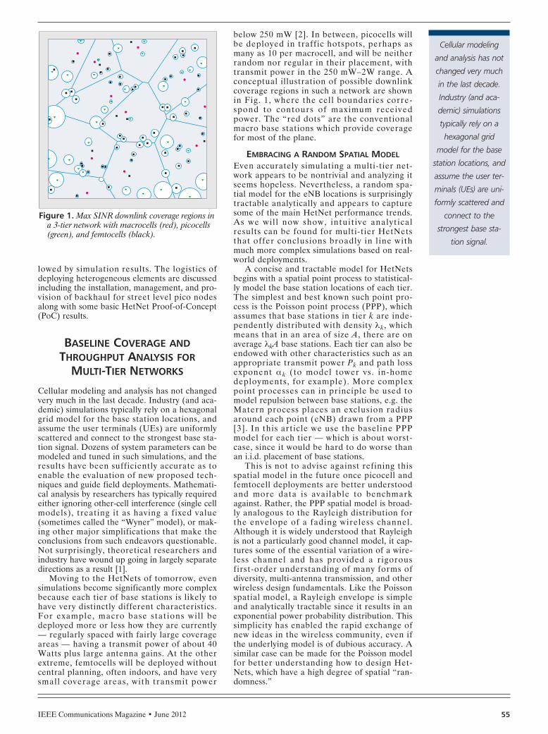
below 250 mW [2]. In between, picocells willbe deployed in traffic hotspots, perhaps asmany as 10 per macrocell, and will be neitherrandom nor regular in their placement, withtransmit power in the 250 mW–2W range. Aconceptual illustration of possible downlinkcoverage regions in such a network are shownin Fig. 1, where the cell boundaries corre-spond to contours of maximum receivedpower. The “red dots” are the conventionalmacro base stations which provide coveragefor most of the plane.
EMBRACING A RANDOM SPATIAL MODELEven accurately simulating a multi-tier net-work appears to be nontrivial and analyzing itseems hopeless. Nevertheless, a random spa-tial model for the eNB locations is surprisinglytractable analytically and appears to capturesome of the main HetNet performance trends.As we wil l now show, intuit ive analyticalresults can be found for multi-tier HetNetsthat offer conclusions broadly in l ine withmuch more complex simulations based on real-world deployments.
A concise and tractable model for HetNetsbegins with a spatial point process to statistical-ly model the base station locations of each tier.The simplest and best known such point pro-cess is the Poisson point process (PPP), whichassumes that base stations in tier k are inde-pendently distributed with density λk, whichmeans that in an area of size A, there are onaverage λkA base stations. Each tier can also beendowed with other characteristics such as anappropriate transmit power Pk and path lossexponent α k (to model tower vs. in-homedeployments, for example). More complexpoint processes can in principle be used tomodel repulsion between base stations, e.g. theMatern process places an exclusion radiusaround each point (eNB) drawn from a PPP[3]. In this article we use the baseline PPPmodel for each tier — which is about worst-case, since it would be hard to do worse thanan i.i.d. placement of base stations.
This is not to advise against refining thisspatial model in the future once picocell andfemtocell deployments are better understoodand more data is available to benchmarkagainst. Rather, the PPP spatial model is broad-ly analogous to the Rayleigh distribution forthe envelope of a fading wireless channel.Although it is widely understood that Rayleighis not a particularly good channel model, it cap-tures some of the essential variation of a wire-less channel and has provided a rigorousfirst-order understanding of many forms ofdiversity, multi-antenna transmission, and otherwireless design fundamentals. Like the Poissonspatial model, a Rayleigh envelope is simpleand analytically tractable since it results in anexponential power probability distribution. Thissimplicity has enabled the rapid exchange ofnew ideas in the wireless community, even ifthe underlying model is of dubious accuracy. Asimilar case can be made for the Poisson modelfor better understanding how to design Het-Nets, which have a high degree of spatial “ran-domness.”
Figure 1. Max SINR downlink coverage regions ina 3-tier network with macrocells (red), picocells(green), and femtocells (black).
Cellular modeling
and analysis has not
changed very much
in the last decade.
Industry (and aca-
demic) simulations
typically rely on a
hexagonal grid
model for the base
station locations, and
assume the user ter-
minals (UEs) are uni-
formly scattered and
connect to the
strongest base sta-
tion signal.
GHOSH LAYOUT_Layout 1 5/22/12 6:07 PM Page 55

IEEE Communications Magazine • June 201256
CHARACTERIZING THESINR DISTRIBUTION OF HETNETS
The single most important and general metric ina cellular network is the SINR distribution.Once the SINR distribution is known, the outageand rate histograms follow immediately, and theoutage or average rate can be easily computed.In a baseline model with no interference man-agement, the SINR offered by a base station atlocation xi to a mobile station at the origin in aK-tier network can be expressed as
(1)
where h is the fading to the UE, σ2 is noisepower, Φ j is the point process for tier j whichhas density λj, and its points x generically referto all the interfering base stations in that tier.The other parameters were defined whenexplaining the spatial model. The outage prob-ability is then simply the event that no basestation in any tier can provide a SINR higherthan the threshold for that tier βi and the cov-erage probability is the complement. The out-age and coverage pc are thus the CDF andcomplementary CDF of the SINR random vari-able, respectively. To be explicit, pc is the prob-ability that the maximum SINR (xi) over allbase stations is greater than some thresholdvalue β.
One could pick an arbitrary set of point pro-cesses and fading distributions and plot theSINR distribution using a Monte Carlo simula-tion. However, applying various techniques andtools from stochastic geometry, it is possible toderive this SINR mathematically. This SINR dis-tribution takes on a very simple closed formunder four additional, but plausible, assump-tions:• Each mobile connects to the base station
with the strongest signal, which is not nec-essarily the closest one
• Noise is negligible vs. interference,• The SINR target is 0 dB or more for each
tier1
• Rayleigh fadingIn this case, the coverage probability can bederived to be [4]
(2)
where C(α) = (2π2/α) csc(2π/α) is a simple con-stant. All four of these assumptions can berelaxed and the SINR can still be computedvery easily without simulation but it is usuallynot closed form2 [5]. It is fairly surprising thatsuch a precise and compact description of SINRcan be achieved for a HetNet system model,when no such formula previously existed evenfor intensively researched one-tier grid-basednetworks. One can immediately observe fromEq. 2 that if all the target SINRs for each tierare the same, i.e. βi = β, which might be a goodapproximation in practice, then Eq. 2 can befurther simplified to
What does this mean? Under a simplifiedmodel of a HetNet — but not a terribly simpli-fied one — it means that coverage probability isin fact independent of what would seem like cru-cial quantities: the number and density of differ-ent types of base stations; the number of tiers;their relative power levels; the fading distribu-tion. In short, one can add tiers to the network,and base stations to any tier; they can have arbi-trary power; and it does not affect the coverageprobability!
This result contradicts the commonly heldbelief that adding femtocells, picocells, andother spectrum-sharing devices to a cellular net-work will erode performance by increasing inter-ference. What this mathematical exercise showsis that in principle, this need not be the case. Aslong as the network is interference-limited andmobiles connect to the strongest base station,statistically speaking, their desired signalimproves just as fast as the interference increas-es, so their SINR distribution does not change.It also shows that complex power control is notnecessarily that important either.
THE IMPORTANCE OF ACCESS MODELS ANDINTELLIGENT CELL ASSOCIATION
Naturally, some caveats should be given to theabove results. First, this model is “open access,”i.e. any UE can connect to any base station, andit connects to the one that offers the best SINR.In practice, this may not occur for two importantreasons. First, some nodes in the network,notably closed-access femtocells, will not beaccessible to the rest of the UEs and so overallcoverage probability may slightly decrease asfemtocells are added. The problem is expectedto be more severe in CDMA systems due to thenear-far problem than in OFDMA where moreorthogonal resources are available. Similarly,high mobility UEs will not always be connectedto the strongest base station since handoverstake some time.
A further important point is that it may behighly suboptimal from a network-wide point ofview for UEs to simply pick the max-SINR basestation, if a weaker one is available that is lightlyloaded. For example, moving a UE from a heav-ily-loaded macro-base station to a nearby lightly-loaded picocell would benefit both that UE aswell as the macrocell users by achieving betterload-balancing. For example, a bias value Bk canbe introduced for tier k, so that a UE will selecta small cell in tier k even if it is a factor Bkweaker than the macrocell. Proceeding with thesame model, [5] shows that with biasing theprobability of a UE associating with a tier k is
Although all these theoretical results are foran idealized HetNet model, we show in the nextsection that the essential intuition of these math-ematical results holds, and that the technical
pC
c =π
α β α( ) /2
p P SINRC
P
Pc
iK
i i i
iK
i
= > = =−
=
∑[ ]
( )
/ /
βπα
λ β
λ
α α1
2 2
1 ii2/α∑
SINR xPh x
P h xi
i x i
jK
x j x j x
i
i
( )\
=+
−
= ∈−∑ ∑
α
α σ12
Φ
AP B
P Bk
k k k k
iK
i i i k
=−
=−∑
λ β
λ β
α α
α α( )
( ).
/ /
/ /
2 2
12 2
1 It is shown in [4] thatthe results hold down toabout –4dB, which coverseven cell edge users.
2 When α = 4, a closed-form expression existseven with noise and arbi-trary SINR.
The problem is
expected to be more
severe in CDMA sys-
tems due to the
near-far problem
than in OFDMA
where more orthog-
onal resources are
available. Similarly,
high mobility UEs
will not always be
connected to the
strongest base sta-
tion since handovers
take some time.
GHOSH LAYOUT_Layout 1 5/22/12 6:07 PM Page 56

IEEE Communications Magazine • June 2012 57
arguments for adding heterogeneous elements tothe existing cellular network are very strong.
SIMULATED PERFORMANCE OFBASELINE HETEROGENEOUS
NETWORKS
In HetNets, LPNs are distributed throughoutan overlay macro-cell network. LPNs are typi-cally small base stations that are classified bythe transmit power and backhaul type asdescribed in [6]. A typical pico cell is formed byan open-access LPN with omnidirectionalantennas rated between 24–33 dBm outputpower, providing standardized interfaces overbackhaul and are deployed in a planned fash-ion. A femto cell is typically formed by a LPNwith antennas rated between 20–23 dBm, pro-viding access to few users, utilizing home broad-band as backhaul and deployed in an unplannedmanner. In this section, the simulated perfor-mance of pico cells with macro-cell overlay issummarized. The results are based on 3GPPscenarios outlined in [7] and compared to theanalysis from earlier.
The LPNs can be deployed using the samecarrier frequency as the macro network(F1–F1), or using a different carrier frequency(F1–F2). First, the performance of multi-tiernetworks without any ICIC techniques is sum-marized for both carrier frequency cases.3 TheUE distribution follows Table A.2.1.1.2-5defined in [8]. Configuration #4a represents alow degree of clustering of users, whereas Con-figuration #4b (performance not shown here)represents a high degree of clustering. In thesimulations, the number of LPNs per sector isvaried from 1 to 10. The following metrics areused to evaluate the performance of the result-ing heterogeneous (equivalently, multi-tier)network.• Average per user throughput for macrocell
UEs, picocell UEs, and a UE that can beeither in a macrocell or picocell.
• The 5th percentile and 95th percentile userthroughput for the same 3 cases
• Total sector throughput• Fraction of UEs attached to picocells
The system simulation parameters are givenin Table 1. The performance of the multi-tiernetwork based on the metrics defined in the pre-vious paragraph is summarized in Table 2 forConfiguration #4a and for transmit mode 3,TM3 (open-loop spatial multiplexing).
The following observations can be made fromthe table: • Gains of up to 4X in average overall UE
throughput and up to 2X in 5th percentileUE throughput can be achieved with thedeployment of 10 pico cells within a macrocell area.
• Overall average and 5 percentile UEthroughput improves as the number ofpicos/sector increases.
• Overall sector throughput improves linearly —although not quite in direct proportion —with the numbers of picos deployed permacro sector. This observation reinforces
the theoretical results of an earlier section,which showed that picocells can be addedwithout in anyway degrading coverage,which implies that each added picocellshould increase capacity.Next the performance of the F1–F1 configura-
tion (10 MHz BW) is compared with the F1–F2(10 MHz BW each for F1 & F2) configurationfor both FDD and TDD systems, and for twoTDD configurations (configurations 1 (TDD C1,DL:UL=~60:40) and 2 (TDD C2,DL:UL=~75:25) are defined in [9]) without anyICIC techniques. Figure 2 shows the averageand 5th percentile picocell UE throughput forthese configurations using TM4 (closed-loopspatial multiplexing), instead of TM3 (open-loopspatial multiplexing). The following conclusionscan be drawn:• The raw picocell UE throughput for F1–F2
is almost doubled vs. F1–F1 since there isno inter-cell interference between themacro and pico layer in the case of F1–F2.However, from a spectral efficiency point ofview the performance of the two configura-tions are the same.
• Raw picocell UE DL throughput (both 5thpercentile and average) is much better with(F1–F2) even with TDD Config-1 comparedto FDD (F1–F1).
• Although both the average pico-cellthroughput and the number of averageUEs attached to each pico decrease withincreasing number of picos/sector, thebehavior of the average UE throughput isdetermined by how their ratio changes.Thus, different trends are observed withF1–F1 and F1–F2, influenced by whetherinterference is dominated by the macro cellor other pico cells.The performance was also evaluated for the
uplink of a HetNet, with results given in Table 3.The conclusions are similar to the downlink withthe main difference being that uplink rates aretypically lower due to transmit power limitations.In fact, the picocell gains are even larger in theuplink for this reason, since the attachment isbased on downlink reference signal receivepower (RSRP) and therefore the attachment tomacrocells is increased since the macrocells havehigher transmit power and antenna gain. There-fore the uplink gain is larger when a UE does infact attach to the picocell since it will have ahigher transmit power on average than when itattaches to a macrocell. Here, we are assumingthat the downlink and uplink attachment mustbe to the same eNB.
ICIC AND ENHANCED-ICICTECHNIQUES TO IMPROVE
COVERAGE
It was noted that without ICIC, the fraction ofusers attached to picocells was between 10–40percent and varied with the density of picocellsper sector (and UE layout). However, the num-ber of users attached to picocells also dependson the propagation environment. To increasethe number of UEs attached to picocells, cell
3 See next section for adescription of some ICICtechniques.
The downside of
biasing is that UEs
are no longer neces-
sarily connected to
the strongest eNB.
As a result, both the
control and data
channel for the
biased users is often
weak and subjected
to strong interfer-
ence. To compen-
sate, enhanced inter
cell interference
coordination tech-
niques are used.
GHOSH LAYOUT_Layout 1 5/22/12 6:07 PM Page 57

IEEE Communications Magazine • June 201258
range extension (also called cell biasing) will beused. Biasing achieves the dual benefits ofdecreasing the load on the macrocell while push-ing UEs onto lightly loaded picocells where theycan receive more resources. The downside ofbiasing is that UEs are no longer necessarilyconnected to the strongest eNB [5]. As a result,both the control and data channel for the biasedusers is often weak and subjected to strong inter-ference. To compensate, enhanced inter cellinterference coordination (eICIC) techniquesare used. In this section, ICIC techniques basedon Release-8 and 10 are presented along withsome system simulation results. We refer readersto [10] for a background tutorial treatment ofkey ICIC techniques, including fractional fre-quency reuse (FFR).
FFR FUNDAMENTALS
The two most common types of FFR are StrictFFR and Soft Frequency Reuse (SFR). As illus-trated in Fig. 3 using three adjacent cells and3–4 non-overlapping frequency bands, the basicidea of Strict FFR is to create partitions betweenedge and inner users based on SINR, reusing theresource blocks (RBs)4 of inner users in everycell and allocating edge users orthogonal FFRRBs, thus removing adjacent cell interference. Inthe case of SFR, higher per-cell RB utilization isachieved by reusing all RBs in every cell butwith a higher transmit power given to edge usersto mitigate the increased inter- and cross-tierinterference. FFR is an attractive ICIC tech-nique because of its simple implementation andability to balance the improvement in user expe-
Table 1. System simulation parameters for DL/UL.
Simulation Parameter Value
Deployment scenario 1, 2, 4, and 10 pico nodes randomly overlaid onto Case 1macro-cells (19-cell, 57-sector wrap-around)
Number of UEs and user dropping criteria 30 per macro-cell sector and 4a/4b
Serving cell attachment RSRP-based
Scheduler Proportional fairness
Bandwidth 10 MHz
Carrier Frequency 2 GHz
Pathloss models As per 3GPP TR 36.814 model 1
Macro cell ISD 500 m
Max Macro Tx Power 46 dBm
Max Pico Tx Power 30 dBm
Noise figure 9 dB
Macro eNB antenna pattern 3D antenna pattern (3GPP TR 36.814)
Pico eNB antenna pattern Omni-directional, 2D antenna pattern
Macro eNB antenna gain 14 dBi
Pico eNB antenna gain 5 dBi
Antenna configuration2 cross- polarized Tx antennas for eNB, 2 VH-polarized Rxantennas for terminal (2 × 2 OL-MIMO, Mode-3)
Receiver type MMSE
Minimum distance between pico and macro 75 m
Minimum distance between picos 40 m
Minimum distance between macro and UE 25 m
Minimum distance between pico and UE 10 m
Fast Fading Channel Modeled
4 An RB is a unit of dataallocation in LTE and isspecifically 12 subcarriersby 14 symbols.
FFR is an attractive
ICIC technique
because of its simple
implementation and
ability to balance the
improvement in user
experience at the cell
edge through fre-
quency reuse while
still maintaining over-
all spectral efficiency
by reusing most RBs
in every cell.
GHOSH LAYOUT_Layout 1 5/22/12 6:07 PM Page 58

IEEE Communications Magazine • June 2012 59
rience at the cell edge through frequency reusewhile still maintaining overall spectral efficiencyby reusing most RBs in every cell.
FFR IN LTEA simple strategy was followed in implementingthe Rel-8 based ICIC scheme for multi-tier net-works. FFR was used in the overlay macro-cellnetwork, where a portion of the time-frequencyRBs was reserved in each sector for cell edgeUEs. In the simulation Soft FFR was utilizedwith 18 RBs out of 50 RBs used in a 3 cell reusepattern for scheduling cell edge UEs and theremaining 32 RBs were used in single cell reusepattern. The underlay picocell network operatedwith single cell frequency reuse scheme withoutany FFR. Table 4 shows the 5th percentile over-all (macro+pico) UE throughput with and with-out Rel-8 ICIC techniques for a multi-tiernetwork. It may be observed that there is 20–40percent improvement in overall cell edgethroughput with no biasing. On the other handwhen using a cell-range extension (CRE) biasand FFR on only the macro-cell layer, the over-all cell-edge performance can be enhanced, butthis enhancement may be difficult to implementbecause of control channel degradation.
The analytical approach presented earlier hasrecently been used to better understand the per-formance of single-tier and heterogeneous net-works using FFR on one or multiple tiers bycapturing the non-uniformity of coverage areas,which directly impact the distribution of edgeuser SINR under FFR, something not possiblebefore with deterministic models [11, 12]. Theanalytical results predict a 5-8 dB increase intypical edge user SINR compared to no ICICwith an ideal control channel. Intuitively, withopen access, the offloading effect of biasingworks in combination with the SINR boost fromthe use of FFR to improve user experience and
reduce the amount of RBs which need to bereserved. As the bias is increased, only the macrousers with the worst SINR are allocated a FFRRB and these are the users who will reap thegreatest benefit from FFR.
Next, Rel-10 based ICIC techniques are dis-cussed briefly. Rel-10 e-ICIC can be broadlyclassified into two categories, namely• Non-carrier aggregation (CA) based
schemes• Carrier based schemes (not discussed in this
article)The non-CA scheme uses a time division multi-plexing (TDM) principle where the macro sendsan almost blank subframe (ABS) or MBSFN(Multimedia Broadcast over Single FrequencyNetwork) subframe pattern with a certain periodalong with the data ICIC frequency partition tothe pico nodes and the pico nodes in turn send asmall amount of long-term information likeRSRP. This ABS approach is illustrated in Fig.4, where the macro node transmits ABSs with a
Figure 2. Picocell performance comparison of F1–F1 to F1–F2 configurationsfor FDD and TDD (Configuration #4a).
Average(F1/F1FDD)
4000
UE
thro
ughp
ut (k
bps)
0Fifth
percentile(F1/F1FDD)
Average(F1/F2FDD)
Fifthpercentile
(F1/F2FDD)
Average(F1/F2
TDD C2)
Fifthpercentile
(F1/F2TDD C2)
Average(F1/F2
TDD C1)
Fifthpercentile
(F1/F2TDD C1)
2 Picos4 Picos10 Picos
2000
6000
8000
10000
12000
14000
Table 2. Performance of multi-tier networks for Configuration #4a (2 × 2, TM3) w/o ICIC.
Throughput typeNumber of Picos/Sector
0 2 4 10
Macro cell UEs
Avg UE t’put 705 769 878 1117
5th percentile UE t’put (kb/s) 126 132 144 194
Sector t’put (Mb/s) 21.2 20.4 20.6 20.2
Pico cell UEs
Avg UE t’put (kb/s) — 4037.1 4422.9 5218.3
5th percentile UE t’put (kb/s) — 601.0 648.8 829.2
Sector t’put (Mb/s) — 7.1 7.2 6.2
All UEs
Avg UE t’put (kb/s) 705.4 1149.5 1649.9 2745.9
5th percentile UE t’put (kb/s) 126.4 139.4 163.2 249.1
Sector t’put (Mb/s) 21.2 34.5 49.5 82.4
Fraction of UEs attached to picos — 0.12 0.22 0.40
GHOSH LAYOUT_Layout 1 5/22/12 6:07 PM Page 59

IEEE Communications Magazine • June 201260
50 percent periodicity but the pico nodes trans-mit normal subframes all the time. The UEsconnected to pico nodes which may suffer frommacro cell interference are scheduled duringtransmission of ABSs from the macros whileUEs closer to pico nodes are scheduled duringnormal macro subframes. Note that this schemerequires strict synchronization between macroand pico nodes and also feedback from the picoand macro nodes over the X2 interface5 to setthe optimum ABS pattern. Figure 5 shows the5th percentile overall UE throughput gain com-pared to the UEs connected to macro cell onlyfor different bias values and ABS patterns andwith and without TDM-eICIC schemes. As anexample ABS fraction of 1/4 signifies that themacro sends 10 ABS frames every four radioframes (40 ms). The following conclusions aredrawn from the figure:• As the bias value increases, the percent of
UEs attached to macrocells decreases.• The overall 5th percentile throughput ini-
tially increases and then drops after about a5-dB bias if no ICIC techniques are applied.
• With Rel-10 TDM-eICIC the bias settingincreases (resulting in more users beingconnected to picocell) along with the per-formance of the overall system. In the case
of Configuration-4b the optimum bias andABS fraction setting are ~15 dB and 1/2,respectively.The results shown are with fixed ABS pat-
tern. In practical deployments the optimal ABSpattern is configured dynamically based on theUE distribution, number of picocells, and othersystem parameters. It may also be noted that toexploit the benefit of TDM eICIC schemes Rel-10 UEs are required. Currently, in Release-11non-zero power ABS frames are also being stud-ied where the PDCCH and PDSCH are trans-mitted at a lower power, while the othercommon channels are transmitted at full powerto maintain coverage.
In addition to TDM eICIC, advanced UEcancellation receivers can also be used to helpovercome the interference due to biasing. Thereceiver is designed to suppress interferencecaused by overhead channels such as commonreference symbols, broadcast channels and syn-chronization signals. Suppression of the legacyinterference from these signals/channelsimproves the decoding performance of both thecontrol and data channels.
DEPLOYMENT LOGISTICS FORHETEROGENEOUS NETWORKS AND
TRIAL RESULTS
While deployment of small cells (e.g. pico, femtoetc.) in a multi-tier network improves the userexperience and capacity of the network it facesmultiple new challenges with respect to backhauldeployment, Enhanced Packet Core (EPC) impactdue to signaling load, ease of management andinstallation, security, electrical power, and theincreased need for efficient self-organizing net-works (SON). In this section, some of the aboveissues will be discussed for specific use cases (e.g.,outdoor street level and indoor pico deployments).Also, we briefly discuss a HetNet field trial.
Figure 3. Strict FFR (left) and Soft FR (right) subband allocations.
f1 and f2f2 and f3
f1 and f3f1 f2 f3f1 f2 f3 f4
Table 3. Uplink performance of multi—tier networks (w/o ICIC) for Configuration #4a.
Number of Picos
Macro cellUes
0 1 2 4 10
Avg UE t’put (kb/s) 336.37 365.99 389.12 442.92 557.97
5th percentile UE t’put (kb/s) 78.51 87.94 92.63 112.93 166.20
Sector t’put (Mb/s) 8.79 8.69 8.63 8.51 7.27
Pico cellUEs
Avg UE t’put (kb/s) — 4940.50 4885.70 4855.30 4894.30
5th percentile UE t’put (kb/s) — 192.48 237.85 344.19 946.41
Sector t’put (Mb/s) — 10.40 9.71 8.73 6.52
All UEs
Avg UE t’put (kb/s) 336.37 636.33 934.67 1447.67 2415.00
5th percentile UE t’put (kb/s) 78.51 90.32 96.71 120.99 192.01
Sector t’put (Mb/s) 8.79 19.09 28.04 43.43 72.455 The X2 interface is alogical link between eNBs.
GHOSH LAYOUT_Layout 1 5/22/12 6:07 PM Page 60

IEEE Communications Magazine • June 2012 61
BACKHAUL CONSIDERATIONS
Today’s traditional cellular systems provide bothcoverage and capacity. With the extensive use ofsmart phones in the future, small cells withLPNs (e.g. picos, femtos, remote radio heads(RRHs)) will address the capacity needs espe-cially in hot zones and clusters while coveragewill be provided by macro cells. One of the sce-narios addressed in this article is the deploymentof pico cells on street poles. The picos needs tobe connected to the core network using wired orwireless backhaul but providing wired backhaulusing fiber from street level picos to the corenetwork may be cost prohibitive compared towireless backhaul. However, wireless backhaulhas its own set of issues which are describedbelow.
Wireless backhaul spectrum can be broadlyclassified in four categories namely• Unlicensed @ 2.4 and 5 GHz• Unlicensed @ 60 GHz• Licensed @ 6–42 GHz and @70–90 GHz• Operator owned licensed band. Specifics of
the various wireless spectrum options forbackhaul are summarized in Table 5.The wireless backhaul between picos in a
street level deployment can be configured inmany different configurations like star, ring etc.The backhaul sizing depends upon how manyhops one has to support, the environment, ifthe pico cells are isolated or clustered, theinterference conditions, the traffic volume, etc.For the pico cells mounted on street poles andusing 2 hops, an unlicensed backhaul at 2.4 or 5GHz can support approximately 50 Mb/s ofthroughput. For street level pico deploymentthe backhaul can be near or NLOS and as suchthe most robust option is to use either unli-censed WiFi or LTE broadband wireless accesssubject to operators’ spectrum asset availability.Note that unlicensed WiFi may suffer frominterference which may affect the robustness ofthe backhaul link.
Picocell deployment using street poles offersmany benefits as seen but the main benefit is theproximity to pedestrians in a semi-urban envi-ronment providing a hot zone in an area wherepeople tend to congregate. Furthermore one cannegotiate with a single entity (e.g. a certainmunicipality or power company) who owns thestreet poles compared a multitude of buildingowners if one were to deploy picos on buildings.However, two vexing issues associated withstreet pole pico deployments are: electric powerand aesthetics. With respect to power, there arepoles with continuous power supply (desirable)or there are poles that have “bank switched”power based on time-of-day. Other alternativesfor power include running independent conduitto supply picos, which can be expensive or rely-ing solar power cell which imposes additionaldesign constraints and makes reliability depen-dent on the weather. Beyond power, aestheticsproves a daunting challenge as the picos must bevisually pleasing and must blend in with theenvironment. Municipalities are sensitive to theappearance of the fixtures in the business andshowing districts and also the aesthetic mustmeet the approval of the local zoning board.
Finally, a brief overview of the HetNet proof-of-concept (PoC) system, which was deployed inEurope at and around a NSN facility operatingat 2.6 GHz is described in this section with somefield results.
The environment is representative of a typi-cal suburban business park with modern two-story glass and steel construction and ampleopen space between buildings with access forpedestrians. The PoC system leveraged anexisting three-sector macro site located on amast in adjacent parking lot used in previousfield trials. Pico sites were deployed on eavesof the facility in a uniform fashion with 4 sitesat the corners and one additional site splittingthe longest side opposite the macro site. Thebuilding was 120 m by 36 m and the macro sitewas only 40 m away. The distribution of picosites was intended to mimic what is envisioned
Figure 4. Transmission of ABS from macro layer (e.g., 50 percent blanking).
Macro layer
Pico layer
One sub-frame
Almost blank, orMBSFN sub-frame
Requires strict time synchronization betweenmacro and Pico
Sub-frame withnormal transmission
Figure 5. Overall 5th percentile UE throughput gain over macro network withCRE and with/without TDM e-ICIC.
Bias (dB)
Fifth percentile UE throughput, 4 picos/macro
5
0.50Gai
n ov
er m
acro
-onl
y
0.00
1.00
1.50
2.00
2.50
3.00
3.50
10
22 35 49 62 7632 47
% UEs attached to picos in config. 4a% UEs attached to picos in config. 4b62 75 85
15 20 250
Config. 4a, w/o ICICConfig. 4a, ICIC (1/4 ABS)Config. 4a, ICIC (1/2 ABS)Config. 4a, ICIC (3/4 ABS)Config. 4b, w/o ICICConfig. 4b, ICIC (1/4 ABS)Config. 4b, ICIC (1/2 ABS)Config. 4b, ICIC (3/4 ABS)
Table 4. Overall (macro+pico) 5th percentile UE throughput using Release-8ICIC.
# Picos per MacroUE Cell Edge Throughput (0 dB bias, kb/s)
W/o ICIC With ICIC percent Change
2, Config#4a 144 201 39%
2, Config#4b 231 280 20%
4, Config# 4a 189 230 22%
4, Config# 4b 261 287 10%
GHOSH LAYOUT_Layout 1 5/22/12 6:08 PM Page 61

IEEE Communications Magazine • June 201262
as typical commercial pico deployment wherepicos are placed on available structures withlittle or no detailed RF planning required bythe network operator. As such, two of thepicos were in direct line-of-sight of the macrosites. These two sites were included to demon-strate that even sub-optimally placed picos canprovide a capacity gain and will not severelyimpact the macro performance. The perfor-mance of the system was evaluated over fourwalking routes — three outdoor and oneindoor — that were selected to follow typicalpedestrian path ways (Fig. 6). 6 UEs were dis-tributed on the identified walking routes atspecific points in the pico coverage areas basedon the CINR CDF — 80 percent, 50 percentand 5 percent points. The results given inTable 6 show a 4X capacity improvement fromthe pico-macro system over macro site alonefor outdoor locations. The highest gains, over6X, are seen on the indoor locations since thelow height of the pico site greatly improves thein-building penetration when Macro power islow. The pico signals need only propagatethrough the windows while the macro signalmust pass through the roof and f loors. Athigher macro powers, a fairly aggressive macrodown-tilt of 10 degrees, designed to coverindoor locations, creates significant interfer-ence at 5 percent point for the indoor loca-tions. With the deployment of picos, the macrodown-tilt may be relaxed further improvingoverall performance.
CONCLUSION
In this article, a theoretical framework of amulti-tier cellular network based on random spa-tial models was developed and it was shown thatessential intuition of these mathematical resultshold in practice. The technical arguments foradding heterogeneous elements to the existingcellular network appear to be very strong. Simu-lation results show that there is a 4X improve-ment in user experience with the deployment ofpicocells in a multi-tier network even withoutany ICIC techniques. Applying TDM based e-ICIC and cell range extension increases thenumber of users connected to the underlay net-work and improves the overall user experiencecompared to a macro cell network. A PoC sys-tem, where the picos were mounted on streetpoles was deployed in Europe and initial resultsshow ~3–4X user-experience improvement overa single-tier macro system.
ACKNOWLEDGMENTThe authors would like to acknowledge Dr.David Chen for giving guidance on backhaulanalysis, Dr. Klaus Pedersen for his insightfulcomments and to Joe Pedziwiatr and Dr. Wei-dong Yang for helping us to enhance our under-standing of various HetNet concepts. They alsoacknowledge the contributions of Prof. FrancoisBaccelli and Prof. Radha Krishna Ganti in help-ing derive some of the featured theoreticalresults. In addition, the authors acknowledge
Table 5. LOS/nLOS/NLOS backhaul options.
Available Frequencies &Bandwidth
Duplex & Lineof Sight (LOS) Range Throughput Latency
Unlicensed2.4GHz and5GHz 802.11a/b/g/n WiFi
2.4000–2.4835 GHz for802.11b/g/n
5GHz UNII band for802.11a/n with 23 available20MHz channels
TDD
LOS/nLOS/
NLOS
< 200 meters with Omniantenna.
LOS up to150Mb/s eachway TDD with802.11n.
1ms ~ 3msper hop
Licensed
6 to 38 GHzMicrowave
6, 7, 8, 11, 13, 15, 18, 23, 24,26, 28, 29, 31, 32, 38 GHz.
16, 32, 64, 128 and 256QAMup to 50 (FCC)/56 (ETSI) MHzchannel bandwidth.
FDD
LOS only
5 to 8 km using mid-range frequencies.
Higher range frequencieswith 1 foot antenna upto 2 miles.
Up to 400Mb/sFDD per link
0.2 to 0.5ms one-way
Unlicensed60GHzV-band
57 to 64 GHzFDD(Typical)/TDD
LOS only
Up to 2 km, stretchableto 3+ km
> 1 Gb/s FDDper link
< 50 usone-way
Light licensed
70 to 90 GHz E-band
71 to 76 GHz81 to 86 GHz92 to 95 GHz
FDD(Typical)/TDD
LOS only
Up to 3 km, stretchableto 5+ km
> 1 Gb/s FDDper link
< 50 usone-way
(best case <5 us)
BroadbandWireless Access(in-band)
2.3GHz, 3.5GhzTDD/FDD
LOS/nLOS/ NLOS
1 to 2 km with sectorantenna
> 2km with directionalantenna
Up to 10 bps/HzOFDMA
< 2ms TDD,
< 1ms FDD
GHOSH LAYOUT_Layout 1 5/22/12 6:08 PM Page 62

IEEE Communications Magazine • June 2012 63
Alex Bonfield, Michael Brien, and David Pad-field for their work on the HetNet PoC system.
REFERENCES[1] M. Dohler et al., “Is the PHY Layer Dead?,” IEEE Com-
mun. Mag., Apr. 2011.[2] V. Chandrasekhar, J. G. Andrews, and A. Gatherer,
“Femtocell Networks: A Survey,” IEEE Commun. Mag.,Sept. 2008.
[3] F. Baccelli and B. Blaszczyszyn, Stochastic Geometry andWireless Networks, Foundations and Trends in Net-working, 2009.
[4] H. Dhillon et al., “Modeling and Analysis of K-TierDownlink Heterogeneous Cellular Networks,” to appear,IEEE JSAC, Mar. 2011, http://arxiv.org/abs/1103.2177.
[5] H. S. Jo et al., ““Heterogeneous Cellular Networks withFlexible Cell Association: A Comprehensive DownlinkSINR Analysis,” submitted to IEEE Trans. Wireless Com-mun., July 2011, available athttp://arxiv.org/abs/1107.3602.
[6] A. Ghosh et al., “LTE-Advanced: Next-Generation Wire-less Broadband Technology,” IEEE Wireless Commun.,vol. 17, no. 3, June 2010, pp. 10–22.
[7] 3GPP TR 36.814, Further Advancements for E-UTRA,v.1.5.2, Dec. 2009.
[8] 3GPP TR 36.913, Requirements for Further Advance-ments for Evolved Universal Terrestrial Radio Access (E-UTRA), v.8.0.1, Mar. 2009.
[9] 3GPP TS 36.211, Physical Channels and Modulation,v8.7.0, May 2009.
[10] G. Boudreau et al., “Interference Coordination andCancellation for 4G Networks,” IEEE Commun. Mag.,vol. 47, no. 4, Apr. 2009, pp. 74–81.
[11] T. Novlan et al., “Analytical Evaluation of FractionalFrequency Reuse for OFDMA Cellular Networks,” IEEETrans. Wireless Commun., vol. 10, no. 12, Dec. 2011,pp. 4294–305.
[12] T. D. Novlan, R. K. Ganti, and J. G. Andrews, “Cover-age in Two-Tier Cellular Networks with Fractional Fre-quency Reuse,” Proc. IEEE Globecom, Houston, TX, Dec.2011.
BIOGRAPHIESAMITABHA (AMITAVA) GHOSH [SM] ([email protected])joined Motorola in 1990 after receiving his Ph.D. in Electri-cal Engineering from Southern Methodist University, Dallas.Since joining Motorola he worked on eight different wire-less technologies starting from IS-95, cdma-2000, 1xEV-DV/1XTREME, 1xEV-DO, UMTS, HSPA, 802.16e/WiMAX/802.16m, Enhanced EDGE and 3GPP LTE. He has 50 issued
patents and numerous external and internal technicalpapers. Currently, he is Head, Wireless Broadband Innova-tion within the CTO office of Nokia Siemens Networks andworks in the area of current and future air-interface tech-nologies for 3GPP LTE, LTE-Advanced and B-4G. Hisresearch interests are in the area of digital communica-tions, signal processing and wireless communications. He isa co-author of the book titled “Essentials of LTE and LTE-A.”
JEFFREY G. ANDREWS has in recent years focused his researchon the coverage and capacity of heterogeneous cellularnetworks, in particular those overloaded with small short-range cells, such as pico and femtocells. He has receivedfive IEEE best paper awards and gave the opening keynoteaddress at the first IEEE Workshop on Femtocell Networks(at Globecom 2010) and has co-authored two popular text-books on 4G cellular standards: Fundamentals of WiMAXand Fundamentals of LTE. He is an Associate Professor atUT Austin, where he is the Past Director of the WirelessNetworking and Communications Group. He is a recipient
Figure 6. Aerial view of the proof of concept system and walking routes.
Table 6. Proof of concept capacity gains for various routes and power settings.
Route Macro(W)
Pico(W)
% MacroCoverage
Percentage Gain
6 UEs Aggregate Throughput
5% 50% 80%
Outdoor
20 2 45% 101% 206% 371%
2 2 23% 86% 342% 392%
0.25 2 9% 57% 247% 448%
0.25 0.25 23% 86% 322% 395%
Indoor
20 2 5% –8% 65% 176%
2 2 0% –1% 104% 233%
0.25 2 0% 37% 241% 536%
0.25 0.25 0% 48% 223% 383%
GHOSH LAYOUT_Layout 1 5/22/12 6:08 PM Page 63
IEEE Communications Magazine • June 201264
of the National Science Foundation CAREER award andholds a Ph.D. from Stanford University.
RAPEEPAT RATASUK joined Motorola in 1999 after receivinghis Ph.D. in Electrical Engineering from Northwestern Uni-versity, Evanston, IL and was a Distinguished Member ofthe Technical Staff in the Wireless Networks Systems andTechnologies department. Currently he is a senior technol-ogist at Nokia Siemens Networks working in CTO’s office.He has extensive experience in 3G/4G cellular systemdesign and analysis (LTE, HSPA, WiMAX, 1xEV-DV, W-CDMA) including algorithm development, performanceanalysis and validation, physical layer modeling and simula-tions. He has 15 issued U.S. patents and over 35 journaland conference papers. His research interests are in theareas of digital communications, signal processing andwireless communications.
BISHWARUP MONDAL received the B.E. and M.E. degrees fromJadavpur University, Calcutta and the Indian Institute ofScience, Bangalore in 1997 and 2000 respectively and thePh.D. degree from the University of Texas at Austin in2006, all in electrical engineering. He is presently withNokia Siemens Networks, Arlington Heights, IL. His currentresearch interests lie in the analysis and design of multipleantenna wireless systems with quantized or partial channelinformation at the transmitter. He is the recipient of the2005 IEEE Vehicular Technology Society Daniel E. NobleFellowship.
NITIN MANGALVEDHE is currently at Nokia Siemens Networks(NSN) working in CTO’s office. Prior to joining NSN he wasa Principal Staff Engineer at Motorola, where he has beenemployed since 1999 after receiving a Ph.D. in ElectricalEngineering from Virginia Tech, Blacksburg, VA. He workedon various wireless access technologies, includingGSM/EDGE/GPRS, WCDMA, IEEE 802.11a/b/g/n, and IEEE802.16m, for several years as part of Motorola Labs, with afocus on advanced receiver algorithms and design of next-generation wireless systems. Since 2008, when he joinedthe System and Technologies group of the Networks divi-sion at Motorola, he has been focusing on modeling,development, and performance analysis of LTE/LTE-Advanced systems. His interests are in wireless communica-tions and digital signal processing.
TIM THOMAS joined Motorola in 1997 after receiving a Ph.D.in electrical engineering from Purdue University. Currentlyhe is a senior technologist at Nokia Siemens Networksworking in the CTO’s office. He was a Distinguished Mem-ber of the Technical Staff in the Wireless Network Systemsand Technologies department and is working on next gen-eration wireless communication systems. His research inter-ests are in channel measurement, channel estimation,MIMO communications, and adaptive antenna algorithmsfor mobile broadband communications.
MARK CUDAK is a senior technologist with the Nokia SiemensNetworks. He manages a research group working on nextgeneration cellular technologies. Prior to joining NokiaSiemens Networks, Mark was with Motorola where heworked on several wireless data systems including GRPS,
WCDMA, HSPA, IEEE 802.16 and LTE. Mark has 37 issuedpatents, was a Motorola Dan Noble Fellow and received aM.S. in electrical engineering at the University of Illinois atUrbana-Champaign.
EUGENE VISOTSKY received a B.S., an M.S. and a Ph.D. inElectrical Engineering in 1996, 1998, and 2000, respective-ly, from University of Illinois at Urbana-Champaign. In June2000, he joined the Communication Systems Research Lab-oratory at Motorola Labs, Schaumburg, IL. Since May 2011,he has been with Wireless Broadband Innovation withinthe CTO office of Nokia Siemens Networks. His main areasof research have included advanced signal processing tech-niques for spread spectrum communication systems, linkadaptation, multicarrier modulation techniques, and multi-hop protocols applied in cellular systems. His current areasof interest are in advanced inter-cell interference coordina-tion and cooperative transmission algorithms. He has anumber of issued and pending US patents.
PING XIA is a Ph.D. student at UT Austin specializing onfemtocell-overlaid cellular networks. He completed his B.E.in 2008 from Tsinghua University, China and his M.S. fromUT Austin in 2010. His research has been supported by NSFand Motorola/NSN and he has held summer internships atDell and Huawei. He has worked on such topics as closedvs. open access and heterogeneous network coordinationand cell association.
HAN-SHIN JO received the B.S., M.S., and Ph.D. degrees inElectrical and Electronics Engineering from Yonsei Universi-ty, Korea, in 2001, 2004, and 2009, respectively. He is cur-rently a Postdoctoral Fellow in the Department of Electricaland Computer Engineering at The University of Texas atAustin. His research interests include theoretical analysisand interference management for femtocell/heterogeneouscellular networks, stochastic geometry and belief propaga-tion.
HARPREET S. DHILLON received the B.Tech. degree in Elec-tronics and Communication Engineering from IIT Guwa-hati, India, in 2008 and the M.S. in EE from Virginia Techin 2010. His Ph.D. research at UT Austin has focused onthe analysis of heterogeneous cellular networks. He isthe recipient of the Microelectronics and ComputerDevelopment (MCD) fellowship from UT Austin and wasalso awarded the Agilent Engineering and TechnologyAward 2008. He has held internships at Qualcomm inSan Diego, CA and Alcatel-Lucent Bell Labs, in CrawfordHill, NJ.
TOM NOVLAN received his Ph.D. at UT Austin working onintercell interference coordination techniques, particularlyFFR. He completed his B.S. degree with High Honors at UTAustin in 2007, where he conducted undergraduateresearch in WNCG on WiMAX systems and the 802.16jmultihop extension in particular. He was a 2006 participantin the NSF Eureca summer research program and is a recip-ient of the Virginia and Ernest Cockrell, Jr. Fellowship. Hehas held summer intern positions at Qualcomm, Intel, andAT&T Labs and is now with Samsung R&D in Richardson,TX.
GHOSH LAYOUT_Layout 1 5/22/12 6:08 PM Page 64