Harley-Davidson SCREAMIN` EAGLE Harley Davidson ... - evedevil
HETA 90-134-2064 NIOSH INVESTIGATORS:September 1990 James D.McGlothlin, Ph.D., M.P.H. Harley-Davidson, Inc. Robert A. Rinsky, M.S.Milwaukee, Wisconsin Lawrence J. Fine, M.D., Dr.P.H.
I. SUMMARY
On January 25, 1990, the National Institute for Occupational Safety and Health(NIOSH) conducted a health hazard evaluation of musculoskeletal disorders of the upperlimbs and back at the Harley-Davidson Motorcycle Company in Milwaukee, Wisconsin. The objective of this evaluation was to identify job tasks in the flywheel milling areawhich may cause, aggravate, or precipitate musculoskeletal injuries, and to providerecommendations to decrease and prevent such injuries.
Approximately 253 motorcycle engines, and 170 motorcycle transmissions arefabricated and assembled each day at this plant. There are approximately 640 hourlyworkers (30% are female); 10 employees work in the flywheel milling area (all aremale). Production is 24 hours per day with 2 to 3 workers working in the flywheel areaper 8-hour shift. Occasionally, these workers may work 10- to 12-hour days to keeppace with production demands. The study included a walk-through survey ofmotorcycle engine fabrication and assembly, a review of OSHA 200 logs and medicalcompensation data, informal interviews with employees, and an in-depth ergonomic assessment of two jobs in the flywheel milling area. Datagathered indicated that potential musculoskeletal disorders could result at the elbow,shoulder, back, and hip during manual material handling of the flywheel during themilling process. Job risk factors which may cause disorders include manual transport ofthe flywheel between milling processes, placement of the flywheel in the millingmachinery, and removal of this part when milling is complete. In addition, hand andwrist disorders may result from exposure to hazardous vibration frequencies from ahand-held power grinder used to remove metal burrs from milled flywheels and duringmanual tightening of this part onto the index milling machine.
Keywords: SIC 3751 (Motorcycle Manufacturing) Musculoskeletal Disorders, ManualMaterials Handling, Cumulative Trauma Disorders, Metal Milling, Motorcycles,Ergonomics, Workstation Design, Engineering Controls.
This Health Hazard Evaluation (HHE) report and any recommendations made herein are for the specific facility evaluated and may not be universally applicable. Any recommendations made are not to be considered as final statements of NIOSH policy or of any agency or individual involved. Additional HHE reports are available at http://www.cdc.gov/niosh/hhe/reports
This Health Hazard Evaluation (HHE) report and any recommendations made herein are for the specific facility evaluated and may not be universally applicable. Any recommendations made are not to be considered as final statements of NIOSH policy or of any agency or individual involved. Additional HHE reports are available at http://www.cdc.gov/niosh/hhe/reports
This Health Hazard Evaluation (HHE) report and any recommendations made herein are for the specific facility evaluated and may not be universally applicable. Any recommendations made are not to be considered as final statements of NIOSH policy or of any agency or individual involved. Additional HHE reports are available at http://www.cdc.gov/niosh/hhe/reports
This Health Hazard Evaluation (HHE) report and any recommendations made herein are for the specific facility evaluated and may not be universally applicable. Any recommendations made are not to be considered as final statements of NIOSH policy or of any agency or individual involved.
This Health Hazard Evaluation (HHE) report and any recommendations made herein are for the specific facility evaluated and may not be universally applicable. Any recommendations made are not to be considered as final statements of NIOSH policy or of any agency or individual involved. Additional HHE reports are available at http://www.cdc.gov/niosh/hhe/reports
applicable. Any recommendations made are not to be considered as final statements of NIOSH policy or of any agency or individual involved. Additional HHE reports are available at http://www.cdc.gov/niosh/hhe/reports
Page 2 - Health Hazard Evaluation Report No. 90-134
II. INTRODUCTION
In January 1990, NIOSH received a request to perform a Health Hazard and TechnicalAssistance (HETA) Evaluation at Harley-Davidson Motorcycle, Inc., in Milwaukee,Wisconsin. The evaluation was requested by the Allied Industrial Workers, theInternational Machinist Unions, and Harley-Davidson Management. Both managementand union officials were concerned about the number of musculoskeletal disordersreported by employees and the medical department which were associated with manualmaterial handling and assembly tasks. Specifically, the company asked NIOSHresearchers for assistance in evaluating musculoskeletal hazards associated withflywheel milling and requested recommendations to reduce such hazards.
On January 25, 1990, NIOSH researchers conducted a walk-through survey of the plant,performed an ergonomic evaluation of job risk factors for musculoskeletal disorders atthe flywheel milling area, and reviewed employee medical record data.
III. WORK FORCE AND PHYSICAL PLANT AND PROCESS DESCRIPTION
Harley-Davidson Motorcycle, Inc., has three plants, one in Milwaukee, Wisconsin,another in Tomahawk, Wisconsin, and the third is in York, Pennsylvania. The plant inMilwaukee, Wisconsin, is responsible for the fabrication and assembly of Harley-Davidson motorcycle engines and transmissions. The plant in Tomahawk, Wisconsin,has 180 hourly employees and 20 salaried, and manufactures nonferrous parts such aswindshields and saddle bags. The plant in York, Pennsylvania, is the largest of the threeplants, with over 1,300 hourly workers and 300 salaried. This plant also does finalassembly of the Harley-Davidson motorcycle.
The Milwaukee, Wisconsin plant, which is the subject of this evaluation, hasapproximately 640 hourly workers and 40 salaried workers. Thirty percent of the workforce is female. The single-story plant was built in the early 1900's and has over200,000 square feet for metal machinery, and 30,000 square feet for assembly. Theplant manufactures and assembles motorcycle parts 24 hours a day, 7 days per week.
Flywheel Milling is located in Department #9. There are three flywheel milling "cells",each cell contains three to four milling machines, a drill press, and two to three worktables for removing medal burrs from post-milled flywheels and for quality controlchecks using calipers to match flywheel dimensions with company specifications.There are two flywheel sizes: the FL, which has a premilled weight of 18 to 19 pounds;and the XL, which has a premilled weight of 15 to 16 pounds. Approximately 3 poundsof metal is cut from each flywheel during the milling process. Each flywheel has a left(sprocket) side and a right (gear) side. When the flywheel is fully assembled, it consistsof a sprocket and gear, crank pin, and two connecting rods. The premilled combinedweight for the left and right flywheel is 37 pounds for the FL flywheel and 31 pounds forthe XL. The weight of fully assembled post-milled flywheels and their components are: FL - 32.5 pounds and XL - 25.6 pounds.
Flywheel milling cells #1 and #2 are used to mill the left (cell #1) and right (cell #2) FLsize flywheel. Flywheel milling cell #3 is used to mill both the left and right sides of theXL size flywheel. The crank pin and connecting rods are fabricated elsewhere in theplant; as is assembly of these components.
Page 3 - Health Hazard Evaluation Report No. 90-134
IV. DESIGN AND METHOD
A. Medical and Epidemiologic Assessment
This plant is faced with an array of circumstances that contribute to the problem ofCTDs among the work force. These circumstances include a workforce made up ofolder workers, often with decades of experience on the same job, and the inherentergonomic stresses present in an operation where machining of heavy componentsis involved. The situation is further complicated by the increase demand for theproduct in recent years, resulting in an inflexible demand for more units resulting inincreased production pressures and more opportunity for work in excess of eighthour shifts. Within the construct of addressing process issues only, we haveattempted to evaluate the ergonomic stresses specific to engineering and workpractices recommendations to lower the levels so as to minimize further injury. However, it should be understood that proper evaluation of ergonomic stressshould be viewed as an ongoing process, always with the aim of reducing stressesfurther by finding the proper balance of process speed, stress, and human factors.
We are unable to propose any epidemiological follow-up to determine theeffectiveness of the interventions we propose, because of the large numbers ofworkers required to determine significance for such interventions. We encouragecontinued monitoring of the occurrence and cost of injuries, which is already beingdone as part of the insurance compensation program. The method, evaluation,results, and recommendations in this report may be used to develop ergonomicintervention strategies in other areas of the plant where you may havemusculoskeletal problems. After you implement these recommendations, the riskof musculoskeletal injury should decrease.
B. Ergonomic Analysis
On January 25, 1990, NIOSH researchers conducted a walk-through survey of themotorcycle engine milling and assembly operations at Harley-DavidsonMotorcycle, Inc. Following the walk-through survey, an in-depth ergonomicevaluation of the flywheel milling area was conducted.
The ergonomic evaluation consisted of: (1) discussions with flywheel millingemployees regarding musculoskeletal hazards associated with their job, (2)videotaping the flywheel milling process, (3) biomechanical evaluation ofmusculoskeletal stress during manual handling of the flywheels, and (4) recordingworkstation dimensions and material process flow. Two flywheel milling cells (#2and #3) were evaluated. Flywheel milling cell #1 was not evaluated, because theworker who normally operates this cell was not available; no replacement workerwas used during this study.
Information gathered during the ergonomic evaluation was analyzed at the NIOSHresearch laboratories in Cincinnati, Ohio. Videotapes of the flywheel milling jobswere analyzed at regular speed for job cycle time, slow motion to determinemusculoskeletal hazards of the upper limbs during manual material handling tasks,and stop-action to sequence job steps and perform biomechanical evaluations ofworking postures. All video analysis procedures were used to document potentialmusculoskeletal hazards in performing the job.
C. Work Documentation and Analysis
Time and motion study techniques were used for the first phase of job analysis.1 Work methods analysis was used to determine the work content of the job. The

Page 4 - Health Hazard Evaluation Report No. 90-134
flywheel milling job is described as a set of tasks, with each task consisting of aseries of steps or elements,1 that is, the fundamental movements or acts such asreaching, grasping, moving, positioning, use, etc., required to perform this job. Though Gilbreth suggested formal element definitions, which were called"Therbligs",2 these elements were arbitrary in that one could increase or decreasedetail as necessary. For example, "get" adequately describes the process of "reach-grasp-move," and "put" for "move-position-release." One identifies work elementsby observing the job or by observing slow-motion videotapes of the job. "Tasks"are groups of elements that are usually performed in the same sequence toaccomplish a common end. Examples of tasks for analysis of the flywheel millingjob include "get flywheel from wheel cart," "position flywheel in milling machine,"and "start milling machine."
The second phase of job analysis was to review the job for recognized occupationalrisk factors for CTDs. These CTD risk factors can be summarized as repetition,force, posture, contact stress, low temperature, and vibration.3,4 In addition,biomechanical evaluation of forces which are exerted on the upper limbs, back, andlower limbs of the worker while performing the task can also be conducted. Suchevaluations are aided by the use of formulas developed by NIOSH5 and theUniversity of Michigan Center For Ergonomics (2D Static Strength SoftwareProgram, version 4.0TM). This two-phase approach for job analysis andquantification of forces which act upon the body during materials handling, formsthe basis for proposed engineering and administrative control procedures aimed atreducing the risk for musculoskeletal stress and injury.
V. BACKGROUND
A. Cumulative Trauma Disorders of the Upper Limbs
Reports of chronic musculoskeletal disorders have been documented as far back asthe year 1717 by the physician, Ramazini, who documented that certainoccupations caused certain violent and irregular motions and unnatural postures ofthe body, which resulted in impairment and disease.6 Several case reports over theyears have cited certain occupational and nonoccupational risk factors which giverise to musculoskeletal injuries.7,8,9,10 However, only recently have epidemiologicstudies attempted to examine the association between job risk factors such asrepetition, awkward postures, and force with excess musculoskeletal morbidity. Several cross-sectional and case-control retrospective studies of occupational CTDshave been employed.11,12,13,14,15,16 The conclusions from these studies have drawn uscloser to identifying risk factors with disease outcome. Work-related CumulativeTrauma Disorders (CTDs) of the upper limbs have been associated with job tasksthat include (1) repetitive movements of the upper limbs, (2) forceful grasping orpinching of tools or other objects by the hands, (3) awkward positions of the hand,wrist, forearm, elbow, upper arm, shoulder, neck and head, (4) direct pressure overthe skin and muscle tissue, and (5) use of vibrating hand-held tools. Becauserepetitive movements are required in many service and industrial occupations, newoccupational groups at risk for developing cumulative trauma disorders continue tobe identified.
One of the most commonly reported disorders of the upper limb is carpal tunnelsyndrome (CTS). CTS is a median neuropathy of the wrist that can be caused,precipitated, or aggravated by repetitive, awkward postures and forceful motions.15 Symptoms of carpal tunnel syndrome (CTS) include pain, numbness, and weaknessof the hand, as a result of compression or irritation of the median nerve as it passesthrough the carpal tunnel in the wrist. Without intervention, CTS can lead tosevere discomfort, impaired hand function, and disability. Workers who perform
Page 5 - Health Hazard Evaluation Report No. 90-134
repetitive tasks are at risk of CTS and include automobile manufacturers andassemblers, electrical assemblers, metal fabricators, garment makers, foodprocessors, grocery checkers, typists, musicians, housekeepers, and carpenters.17,18,4
The diagnosis is confirmed by physical examination and/or electrodiagnosticstudies.18 CTS can be managed with conservative measures, such as wristimmobilization and nonsteroidal anti-inflammatory medications.17 However, thesemethods are not recommended as the main course of action, because symptoms arelikely to recur when the patient resumes the precipitating tasks.17 Recognition andevaluation of work-related risk factors which may cause CTS should be conductedin order to implement controls to reduce such risk factors. Engineering controls arethe preferred method, with administrative controls such as work enlargement,rotation, etc., as an interim measure. For all patients with symptoms suggestive ofCTS, an occupational history should be obtained that includes a description of tasksinvolving use of the hands. Failure to eliminate contributory job factors can resultin recurrence or progression of symptoms, impaired use of the hand, and the needfor surgical treatment. Redesign of tools, workstations, and job tasks can preventoccurrence of CTS among coworkers.17 Surveillance of work-related CTS,including the use of health-care-provider reports, can aid in identifying high-riskworkplaces, occupations, and industries and in directing appropriate preventivemeasure.19
B. Back Injuries
Eighty percent of all Americans will suffer low back pain sometime during theirlifetime.20,21,22,23 Over 30 million Americans currently experience low back pain;24
13 million of those cases have resulted in reduced ability to function.25 Ten millioncases of back impairment are in the employed U.S. population between the ages of18 and 64.25 Lost time from work has increased significantly over the past30 years, while the incidence of low back pain has stayed the same.26 Estimatedtotal costs for low back pain is approximately 16 billion annually (compensable andnoncompensable) in the United States.24 The distribution of low backcompensation costs is skewed: 25 percent of low back cases account for 95% ofthe costs.27 Current estimates for low back compensation costs are approximately6,807 dollars as the average or mean costs, and 390 dollars for the median.27 Thelarge difference between the mean and median shows that costs for low back painare not evenly distributed where a few cases account for most of the costs.27 Thehigher cost for the few cases were attributed to more hospitalization, surgery,litigation, psychologic impairment, and extended loss of time from work. Age,gender, and occupation are risk factors for the occurrence and severity of low backinjuries. Old workers are more likely than younger workers to have severe backdisorders.28 More women than men are likely to have restricted-activity, beddisability, and work loss days.29 Construction, Mining, Transportation, andManufacturing are the occupations which show high rates of low back injuries.30
Occupational risk factors for low back injuries include manual handling tasks,31
lifting,32 twisting,32 bending,32 falling,31 reaching,33 excessive weights,34,32,35
prolonged sitting,36 and vibration.37,38 Some nonoccupational risk factors for lowback injury includes obesity,39 genetic factors,40 job satisfaction.41,42
Return to work following a back injury is dependent on the extent of injury asmeasured by the amount of time away from the job; the longer the worker wasaway from the job the less likely the worker would return to work.43,44 Deterrentsto returning to work include the worker such as psychological disability,management, no follow-up or encouragement, union, rigid work rules; thepractitioner, too much treatment;45 and attorneys, lump sum payment versus

Page 6 - Health Hazard Evaluation Report No. 90-134
rehabilitation [rehabilitation is 4.5 times higher, on average than lump sumpayment].46
Control and prevention of low back pain can be accomplished through theevaluation of jobs and the identification of job risk factors. Bending, twisting,reaching, handling of excessive loads, prolonged sitting, and exposure to vibrationare recognized risk factors for back injuries. Redesign of jobs can lead to thereduction of these risk factors and good job design initially will prevent backinjuries. To reduce bending, twisting, and reaching by the worker, the work shouldbe at the optimum work level - from waist to elbow height to reduce excessivebending and reaching; the workplace should be well laid out so as to reducetwisting; sit/stand workstations should be allowed where possible with good seatdesign so as to reduce prolonged sitting and standing; good package design such ashand holes for better coupling by the worker, package size so the worker can holdthe load close to the body, and package weight so as not to exceed humancapabilities.5 Interim changes to reduce back injuries include job placement;47
strength and fitness testing;48,49,50 strength and fitness training (work hardening),51,52
and work enrichment, enlargement, or rotation to reduce cumulative exposure. Inaddition to educating and training the worker, unions, and management about riskfactors which cause back injury and pain, there appears to be no clear, singlesolution other than good initial job design. Multiple approaches such as jobredesign, worker placement, and training may be the best methods for controllingback injuries and pain.53
Evaluation Criteria for Risk of Back Injury
The NIOSH Work Practices Guide for Manual Lifting,5 was developed usingmedical, scientific, and engineering resources to develop quantitativerecommendations regarding the safe load weight, size, location, and frequency of alifting task. The recommendations assume that
1. the lift is smooth
2. the lift is two-handed and symmetric in the sagittal plane (directly in front ofthe body with no twisting during the lift)
3. the load is of moderate width, e.g., 30 inches or less
4. the lift is unrestricted
5. the load has good couplings (handles, shoes, floor surface)
6. the ambient environment is favorable
It is further assumed that other material handling activities such as holding,carrying, pushing, and pulling are minimal; that the individual performing thelifting activities is at rest when not lifting; and those involved in lifting arephysically fit and accustomed to labor.
Page 7 - Health Hazard Evaluation Report No. 90-134
The formula used to analyze the various tasks is as follows:
Action Limit (AL) (lbs) = 90 (6/H) (1-.01|V-30) (.7+ 3/D) (1-F/Fmax);(Maximum Permissible Limit (MPL) = 3 AL); where:
H = horizontal location forward of midpoint between ankles at origin ofliftV = vertical location at origin of liftD = vertical travel distance between origin and destination of liftF = average frequency of lift (lifts/minute)Fmax = maximum frequency which can be sustained (table of valuesprovided in Work Practices Guide)
Tasks analyzed in this manner are divided into three categories:
1. those above the Maximum Permissible Limit (MPL) which are consideredunacceptable and which require engineering controls
2. those between the AL and MPL which are unacceptable withoutadministrative or engineering controls
3. those below the AL which are believed to represent nominal risk to mostindustrial work forces.
The Work Practices Guide indicates that corrective action is needed for jobs whichexceed the Action Limit. The incidence and severity rates of musculoskeletalinjury have been found to increase in populations "exposed to lifting conditions"described by the Action Limit. It has been determined that over 75% of womenand over 99% of men could (safely) lift loads described by the Action Limit.
C. Segmental Vibration
For more than 75 years, workers who operated vibrating tools on the job havereported symptoms resembling the signs and symptoms of primary Raynaud'sdisease.54 These symptoms included episodic numbness and tingling of the fingers,episodic blanching of the fingers, with pain occurring in response to cold exposureand on return of circulation, and reduction in grip strength and finger dexterity. These signs and symptoms increased in number and severity as the exposure tovibration increased.54
It is estimated that 1.45 million workers use vibrating tools in the United States.55 Worker populations which use vibrating tools have reported the prevalence ofHand-Arm Vibration Syndrome (HAVS) ranging from 6 to 100 percent. Riskfactors for HAVS depends on many factors such as: the vibration energy producedby the tool, the length of time the tool is used each day, the cumulative number ofhours, months, and years the worker has used the tool, and the ergonomics of tooluse.
HAVS may take months or years to develop, and can be reversed in the early stageswhen recognized. However, advanced stages of HAVS are not reversible and leadto loss of effective hand function and necrosis of the fingers. Engineering controls,work practices, administrative procedures, medical supervision, worker training,ergonomic design of the tools and the task, and other procedures can beimplemented to effectively reduce the risk of developing HAVS. While no specificRecommended Exposure Limits are provided in the NIOSH Criteria Document onHand-Arm Vibration, it is recommended that engineering controls be the first level

Page 8 - Health Hazard Evaluation Report No. 90-134
of protection through: (1) the elimination or reduction at the source (controllingacceleration of the tool), (2) reduction of transmission (the use of energy-dampingmaterials between the tool and the worker's hands), and (3) process modification(ergonomic analysis and evaluation of work processes to determine vibrationexposure sources and their elimination). Good work practices are alsorecommended, as are worker training and medical monitoring.54
VI. RESULTS
Ergonomic Evaluation and Analysis
1. Work Content
FL Flywheel Milling: The flywheel milling Cell #2 (FL-right side) operatorperformed a series of steps to mill the motorcycle flywheel to companystandards. Seventy to 75 flywheels are milled per 8-hour shift in which 3pounds of metal is cut from the right-side flywheel during this process. Adescription of the basic milling steps for the FL right side flywheel is shown inTable 1. The milling machines and work flow to complete the flywheelmilling task is schematically shown in Figure 1.
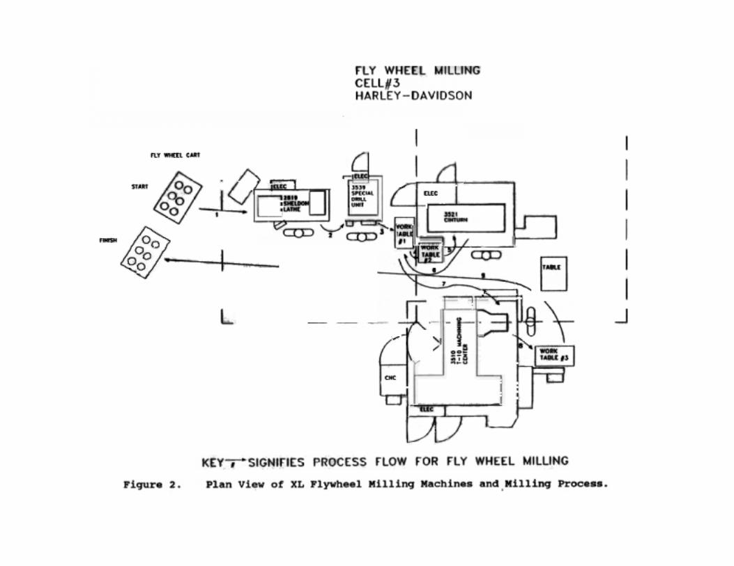
XL Flywheel Milling: The flywheel milling Cell #3 (XL right and left side)operator performed a series of steps which were similar to the worker in Cell#2. Seventy-five to 80 flywheels are milled per 8-hour shift in which 3pounds of metal is cut from the right and left sides of the flywheel during thisprocess. The basic milling steps for the XL flywheels are described in Table2. The milling machines and work flow to complete the flywheel milling taskis schematically shown in Figure 2.
2. Cumulative Trauma
During the ergonomic evaluation of the flywheel milling jobs in flywheelmilling work Cells #2 and #3, it was determined that these jobs were repetitiveand required occasional awkward postures. There was considerablecumulative force involved in the form of flywheel lifting, movement, andprocessing during the work cycle. As such, in-depth analysis of the force riskfactor was conducted to determine how much cumulative force, in the form ofweight, each worker was exposed to each 8-hour workday. Tables 1 (FLflywheel milling) and 2 (XL flywheel milling) also show which work taskshad forceful motions that could be semi-quantified as a function of flywheelweight, when the flywheel was lifted, moved and positioned during the workprocess, which hand is involved in performing these motions, and the type ofhand grip (pinch or power) used during these motions.
Cell #2: FL size flywheels have a premilled weight of approximately 19pounds. After milling, these flywheels weigh approximately 16 pounds. Jobanalysis from videotapes taken during the NIOSH survey showed that the jobcycle time to process flywheels ranged from 4 to 6 minutes, depending on theadditional activities by the worker to prepare the machines for milling,material movement, milling time, and grinding (removal of metal burrs). Itwas determined that the job was comprised of 37 steps, in which the worker inflywheel milling Cell #2 performed approximately 45 definable job motions inwhich lifts, movements, and processing activities were done to complete onework cycle. Twenty-three of the 45 definable job motions could be semi-quantified by the amount of weight moved (average weight of the FL flywheel

Page 9 - Health Hazard Evaluation Report No. 90-134
was 17.5 pounds) per job cycle. The amount of weight moved could betranslated to terms

Page 10 - Health Hazard Evaluation Report No. 90-134
of force (i.e., lifting and moving the flywheel from one location to anotherduring the work cycle). Force, as it is used here can be expressed in terms ofNewton's second law, where the time rate of change of momentum isproportional to the force which produces the change.56
Approximately 10 to 11 flywheels are milled per hour, with 70 to 75 milledper 8-hour shift. The estimated amount of accumulated weight handled by thisworker is as follows: Average weight: 17.5 pounds (average 19 to 16pounds), the number of times the flywheel was lifted, moved, and positioned(where force could be measured) per work cycle was 23; resulting in anaccumulated number of pounds handled per work cycle at 402.5 pounds. If 10flywheels are processed per hour with 7 hours of exposure (1 hour is for 10-minute work breaks, 2 in the morning and 1 in the afternoon, and 30 minutesfor lunch), this results in an accumulated number of pounds handled per shiftof 28,175 pounds (Table 3).
Additional factors which also increase force on the musculoskeletal system(but could not be measured or semi-quantified) should also be considered,such as how the flywheels are handled (pinch versus power grip), by whichhand, and how often. For example, using the pinch grip (i.e., holding the partbetween the distal portions of the fingers and thumb - as in pulling a bookfrom a bookshelf) versus the power grip (wrapping the fingers around theobject - as in holding a hammer or baseball bat) can make a difference withregard to the amount of force required to do the job. The pinch grip is at abiomechanical disadvantage compared to the power grip, where pinch gripsrequire more muscle strength which stresses the hand tendons and is morefatiguing than a power grip. During this evaluation, it was determined that ofthe 23 work elements which involved lifting or movement of the flywheel, 9were done with the left hand, 11 with the right hand, and 3 were done withboth hands. Of the 9 elements involving the left hand, 6 involved a powergrip and 3 the pinch grip. Two of 11 work elements were done with the pinchgrip of the right hand (Table 4).
The remaining 17 work elements performed to complete the work cycle of 45elements were: removal of metal burrs (using a hand-held, in-line poweredgrinder) from the flywheel after milling in the CMC lathe and MachiningCenter; loosening and tightening the flywheels on the Shuttle's loading andunloading pallet (3510 T-10 Machining Center); and use of the air hose toblow off metal debris and oil. Removal of metal burrs was the most timeconsuming of these other activates (15%, or 33 seconds of 4:06 minutes of onework cycle), and appeared to be a risk factor for the development of hand andarm vibration related disorders.
Cell #3: XL size flywheels have a premilled weight of approximately 16pounds. After milling, these flywheels weigh approximately 13 pounds. Jobanalysis from videotapes taken during the NIOSH survey showed that the jobcycle time to process flywheels also ranged from 3 to 5 minutes. The changein cycle time depended on the additional activities by the worker to preparethe machines for milling, material movement, milling time, and grinding time(removal of metal burrs). It was determined that this job had 25 steps inwhich the worker in flywheel milling Cell #3 performed approximately 37lifts, movements, and positioning activities to complete one work cycle. Seventeen of the 37 activities described above involved forces which could bemeasured in terms of flywheel weight (average weight of 14.5 pounds) forlifting, moving, and positioning, the flywheel from one location to anotherduring the work cycle.
Page 11 - Health Hazard Evaluation Report No. 90-134
Approximately 11 to 12 flywheels are milled per hour, with 75 to 80 milledper 8-hour shift. The estimated amount of accumulated weight handled by thisworker is as follows: Average weight: 14.5 pounds (average 16 to 13pounds); the number of times handled per work cycle was: 17; resulting in anaccumulated number of pounds handled per work cycle at 246.5 pounds. If 11flywheels are processed per hour with 7 hours of exposure (1 hour is for two10-minute work breaks in the morning and one 10-minute in the afternoon,with 30 minutes for lunch), this results in an accumulated number of poundshandled per shift of 18,980 pounds (Table 3).
As with Cell #2, the additional factors which add musculoskeletal strain frommaterial handling includes how the flywheels are handled, by which hand, andhow often. It was determined that of the 17 work elements which involvedlifting or movement of the flywheel, 8 were done with the left hand, 9 with theright hand. Of the 8 elements involving the left hand, 1 involved a pinch grip,no pinch grips were observed with the right hand for flywheel lifting,movement, or positioning (Table 4). The remaining 20 work elementsperformed to complete the work cycle were: removal of metal burrs (using ahand-held, in-line powered grinder), from the flywheel after milling in theCMC lathe and Machining Center; loosening and tightening the flywheels onthe Shuttle's loading and unloading pallet (3510 T-10 Machining Center); anduse of the air hose to blow off metal debris and oil. Removal of metal burrsconsisted of a larger percentage of the job cycle time (20 percent, or 39seconds of 3:18 minutes for the work cycle), when compared with thepercentage of time this activity was performed per work cycle in Cell #2. Metal grinding of the flywheels appeared to be a risk factor for thedevelopment of hand and arm vibration related disorders for this job.
3. Biomechanical Evaluation
Biomechanical evaluation of musculoskeletal forces on the upper limbs, back,and lower limbs for these jobs showed that certain job steps put these workersat risk for musculoskeletal disorders in which the allowable limits wereexceeded for certain segments of the worker population. When the allowablelimits are exceeded for certain elements of the job, then it is recommendedthat administrative or engineering controls be implemented. A comprehensiveexplanation of how the NIOSH allowable limits and maximum permissiblelimits were derived may be attained from the Work Practices Guide forManual Lifting.5 Strength predictions for each of the major articulations(joints) are explained in the textbook: Occupational Biomechanics.57
Cell #2 - Flywheel Milling: The biomechanical evaluation using theUniversity of Michigan 2D Static Strength Prediction Program Version 4.0TM,showed that there were some tasks that would exceed the biomechanical andstatic strength capabilities of this worker in relation to the demands of the job. Eighteen pounds of weight was used to simulate the weight of the flywheel;anthropometric data was adjusted to the dimensions of this worker who was inthe upper 5 percentile (95th percentile) for the size and weight of theAmerican male population. Posture and link angles were determined fromstop action analysis of videotapes during the job cycle. Since one hand wasused to perform the task, this was entered into the model.

Page 12 - Health Hazard Evaluation Report No. 90-134
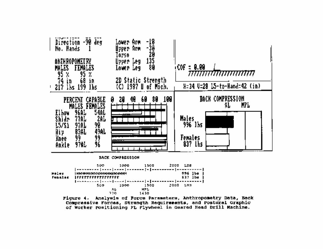
Based on observation of the all the work elements in the job cycle, it wasdetermined that one of the most biomechanically unsound postures was fromplacement of the flywheel in the Geared Head Drill Machine (see Table 1, step#5, and Figure 3). Analysis showed that the compressive forces on the backwere 996 pounds and exceeded the NIOSH allowable limit (AL) of 770pounds (Figure 4). In addition, the strength required to perform this jobexceeded the NIOSH AL for the worker's elbow, shoulders, hip, and ankle,while performing this task (Figure 4).
When compressive forces exceed the NIOSH AL, administrative orengineering controls are recommended to decrease such forces and reduce theprobability of musculoskeletal injury, especially the back. Reducing the reachdistance between the worker and the flywheel by removing physical barriers isone of the easiest methods of control. Other control methods include reducingthe weight of the object, use of two hands during lifting and transporting ofloads, and automation.
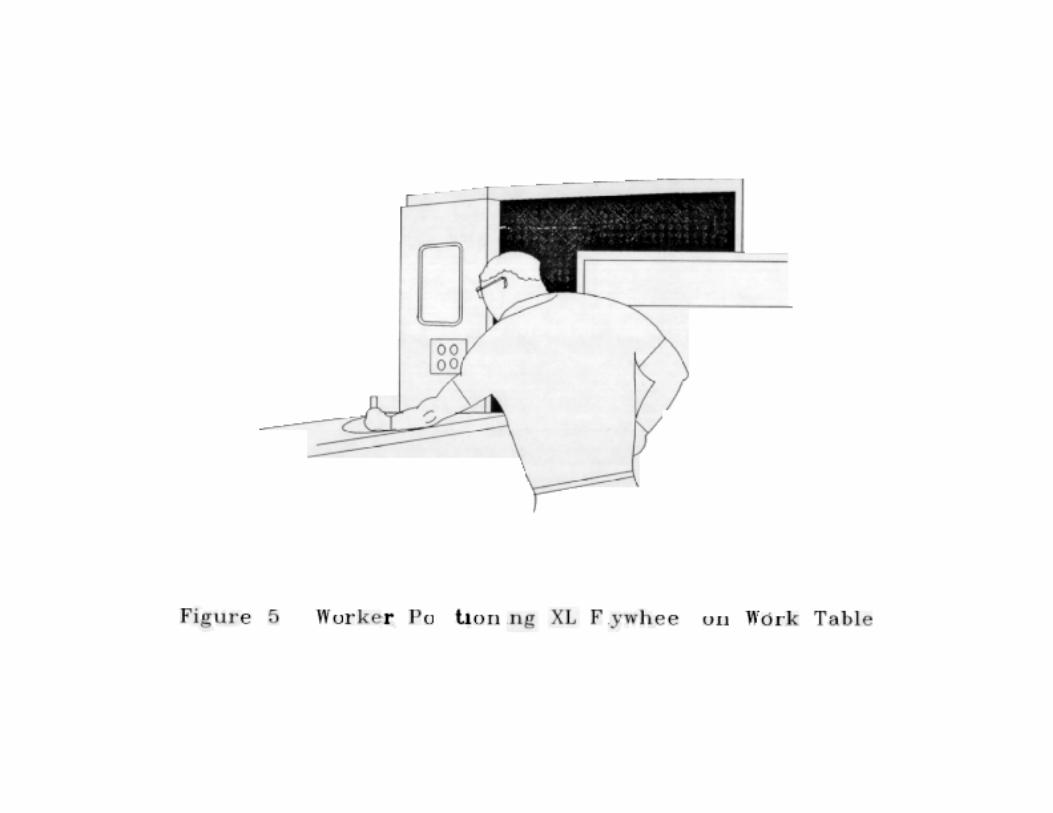
Cell #3 - Xl Flywheel Milling: A biomechanical evaluation was also done forthis workstation using the University of Michigan 2D Static StrengthPrediction Program, V4.0TM. Based on stop action analysis of the videotapefor this job, it was determined that there were excessive strength requirementswhile the worker was removing the flywheel from the 3510 T-10 indexingmachine and placing the flywheel on the work bench (see Table 1, step #11,Figure 5). Biomechanical analysis showed that the compressive forces for thelow back did not exceed the AL of 770 pounds (Figure 6). However, thestrength required to perform this job exceeded the AL for the elbow, shoulder,back (excluding low back), hip, and ankle (Figure 6). Administrative andengineering controls are recommended when such strength requirements areexceeded so as to reduce the chance of musculoskeletal disease and injury. Reducing the distance between the worker and where the worker has to placethe flywheel will reduce the strength requirements for the job. This can bedone by removing physical barriers in front of the worker from the floor to theworking level. If physical barriers are not a problem, then the worker shouldbe instructed to hold the flywheel closer to the body, using two hands whennecessary, when putting the flywheel in place.
VII. DISCUSSION
This evaluation showed that there was excess musculoskeletal stress from flywheelhandling. The musculoskeletal stress was from analysis of material handling during thework cycle and for biomechanical analysis of selected work elements during the workcycle. There was ample evidence to show that there was cumulative musculoskeletalstress during the work cycle and over the work shift. For example, the worker in Cell #2(FL flywheel) lifted, moved, and positioned over 28 thousand pounds of metal flywheelsover an 8-hour period, while the worker in Cell #3 (XL flywheel) lifted, moved, andpositioned nearly 19 thousand pounds of metal flywheels during this same period. These estimates are conservative, since the total amount of weight handled by bothworkers is based only on what could be observed (lifts, movements, and positioning offlywheels on machines) and reliably counted (i.e., average flywheel weight - FL 17.5pounds, XL 14.5 pounds). Static holding of these parts during grinding of metal burrs,tightening and loosening of bolts on the 3510 T-10 centering machine shuttle, and subtlemovements of the flywheels also added to the cumulative musculoskeletal stress butcould not be quantified. Even as a conservative estimate, the amount of weight handledon a daily basis puts these workers in a very exclusive group of individuals who havedeveloped the strength and endurance to sustain such workloads.

Page 13 - Health Hazard Evaluation Report No. 90-134
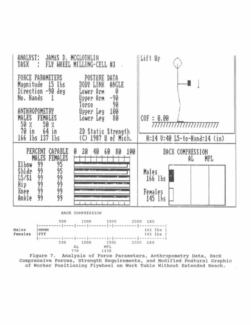
The biomechanical analysis of job tasks showed that in some instances compressiveback forces exceeded the NIOSH allowable limits (AL) and should be controlledthrough administrative or engineering controls. Administrative controls may be in theform of education and training the workers about methods of material handling. Forexample, if the worker in Cell #3 holds the flywheel closer to the body during lifting andtransport, then the biomechanical forces and strength requirements are greatly reduced. Figure 7 shows how biomechanical forces and strength requirements can be reducedthrough proper materials handling. Often proper materials handling can not be done ifphysical barriers are between the worker and where the work is being done. In theseinstances barriers from the floor to the working level should be removed or relocated.
The biomechanical evaluation was conservative because of the restrictions inherent inthe 2D Static Strength Model that was developed from the NIOSH Work PracticesGuide. Such restrictions include (1) lifting a load directly in front of the body with notwisting. That is, the load should be lifted symmetrically (i.e., with two hands); (2) thelift should be done with equal loading of the muscle joints; (3) the lift should be smooth;and (4) the load should be unrestricted during the lift. As noted earlier in this report,such conditions did not exist for the workers evaluated by NIOSH researchers.
Therefore, the biomechanical predictions for risk of injury to the various bodylinks may be underestimated.
Segmental vibration of the hands and arms may also be a risk factor for musculoskeletalstress, notably hand-arm vibration syndrome. This syndrome may result from grindingmetal burrs from the flywheels and the amount of time spent performing this task. InCell #2, the FL flywheel worker spent approximately 15 percent of his cycle timeperforming grinding work, while the worker in Cell #3, the XL flywheel worker spent20 percent of the job cycle grinding away metal burrs from flywheels. This means thatthe worker in Cell #2 is exposed to potentially hazardous vibration for approximately 63minutes per day, while the worker in Cell #3 is exposed to potentially hazardousvibration for 84 minutes per day.
The work flow for Cell #2, the FL flywheel milling area, appeared reasonably well laidout although there was excess handling of the flywheels that resulted from the grindingoperations that should be reduced. The process flow for Cell #3, the XL flywheelmilling area, could be reduced by relocating the finished or post-milled flywheel cartnext to the 3510 T-10 Machine Center and work table. This will reduce the addedamount of musculoskeletal stress associated with manually transporting the flywheelsapproximately 45 to 50 feet to the back of the workstation.
Exact quantitative information does not exist in the published literature for the cause andeffect of manual materials handling and risk of injury. However, the associationbetween the amount and weight of materials handled and risk of injury suggests thateven the strongest workers may not be able to sustain the workloads observed during theNIOSH evaluation. A prudent course of action would be to reduce the cumulative stressof materials handling by considering and implementing the recommendations whichfollow.
Conclusions
Several work tasks were evaluated for musculoskeletal disorders and injury for the FLFlywheel milling job in Cell #2, and the XL Flywheel milling job in Cell #3. Liftingand transporting flywheels during the milling process showed that the cumulative weightwas in excess of 14 tons (28,175 pounds) for the worker in Cell #2, and in excess of 9tons (18,980 pounds) for the worker in Cell #3. The estimates of weight handled areconservative because other work activities such as holding and positioning the flywheels

Page 14 - Health Hazard Evaluation Report No. 90-134
with the hands, the type of hand grip used to handle the flywheels (pinch versus powergrip), as well as

Page 15 - Health Hazard Evaluation Report No. 90-134
segmental vibration exposure from the use of a hand-held power grinder were added riskfactors. Tables 5 and 6 summarize the job steps shown in Tables 1 and 2, respectively,they note which of these job steps are risk factors for musculoskeletal disorders, andpresent recommendations for decreasing such risk factors.
VIII. RECOMMENDATIONS
Ergonomic Evaluation
A. Engineering Controls
1. The Harley-Davidson workers and management should continue to workclosely in their "Vision" circles to determine how the initial weight of theflywheel can be reduced and thereby reduce the cumulative musculoskeletalstresses associated with the job over the work shift. An excellent example ofworker-company collaboration for ergonomic solutions through vision circlesis noted in the development of the plastic wheel-cart used at the flywheelworkstations. A similar approach is encouraged for determining how theflywheel weight can be reduced by the supplier.
2. Reduce the initial weight of the flywheels by improving forging specificationsand thereby reducing milling time and the amount of weight handled,especially for Cell #2, in which this worker handles over 14 tons of metal eachday. Harley-Davidson engineers should consult with the supplier forimproved forging specifications which should reduce costs per part, forshipping, milling, and hazardous waste removal (metal scrap and oil), andstorage.
3. Reduce or eliminate exposure to the powered hand grinder used by workers toremove metal burrs from flywheels, especially for Cell #3, in which 20 percentof the work cycle consists of vibration exposure from tool use. Options toconsider for reducing exposure include:
a. Improved maintenance of drill bits and lathe blades, so that the edges arekept sharp and the flywheels can be milled true to minimize metal burrs. The maintenance program may include regular changing of drill and latheblades with ones that are professionally sharpened.
b. A pea-shot machine, where shot may be used only on areas where metalburrs exist.
c. A tumbling machine to remove the burrs from the flywheel.
4. If the powered hand grinder is used to "touch-up" areas on the flywheel toremove metal burrs, it is recommended that the vibration spectrum of this toolbe evaluated to determine if the vibration frequency is in the hazardous range(25 to 250 hz) to cause vibration-related disorders of the hands, includingRaynolds syndrome. Check tools which do not have a hazardous frequencyrange through manufacturers who make such tools and have the performancespecifications of the tools. Also, change grinding bits on tools frequently toreduce the manual force on the tools needed to remove the metal burrs.
5. A jig should be fabricated to secure the flywheel during the hand-grindingprocess. As viewed on the videotape, the workers free hand is used as a jig, orclamp, and results in unnecessary forces to hold the flywheel as well as
Page 16 - Health Hazard Evaluation Report No. 90-134
inefficient use of this hand. Consider fabricating a turntable-type jig with anattached quick clamp to secure the flywheel when using the grinder.
6. Organizational Layout and Process Control for Flywheel Milling.
a. Flywheel milling cell #2: The flywheel is normally handled 45 times perjob cycle from the time it is removed from the premilled wheel cart to thetime it is placed back in the post-milled wheel cart. Each time theflywheel is handled, this results in musculoskeletal stress of the upperlimbs and back. Consider flywheel handling carts and/or gravityconveyors between flywheel milling stations to reduce musculoskeletalstress.
b. Flywheel milling cell #3: Reduce manual handling by using gravityconveyors and material handling carts.
c. The post-milled flywheel cart for Cell #3 should be moved from the backof the cell to the front where the flywheel can be put into the cart ratherthen manually transporting it to the back of the workstation (see Figure 8for recommended process flow and location of the finished or post-milledflywheel).
d. The 3521 Cinturn unit appears to slow down the work flow. There alsoappears to be an abnormal amount of grinding of metal burrs from theflywheels when they come out of this machine. Check the lathe bits forsharpness and replace if needed. Consider mechanisms for speeding upthe 3521 Cinturn unit processing time for the flywheels. This could be anarea where engineers can work to improve forging specifications toreduce metal cut from the flywheel.
7. The metal pan that is built around the base of the indexing machine should becontoured, by rounding the corners to reduce contact trauma of the worker'supper legs and to reduce the reach distance for putting the flywheels on theindexing machines. Put an emergency stop switch on the machine to avoidpinch points during shuttle rotation.
8. Install floor matting around all three flywheel milling cells to reduce lowerextremity fatigue of workers. The matting should be of a rubberized materialthat can be easily cleaned to reduce build up of metal debris.
9. Remove all physical barriers that may cause workers to overreach, such aslimited toe and leg space where the worker has to reach over barriers tomanually position flywheels for processing.
B. Work Practices
1. When manual handling of the flywheel is necessary, workers should use the"power grip" rather than the "pinch grip." The "pinch grip" requires handlingof the flywheel by the fingertips and thumb, resulting in high musculoskeletalforces and fatigue. The power grip uses all of the fingers and the thenareminences of the palm and results in less musculoskeletal stress and overallfatigue. Use of two hands is also recommended when handling parts to reduceasymmetric biomechanical loading of the limbs and back.
2. When wheel carts are brought into the flywheel milling cell, they should bebrought in with the cart bumper facing away from the traffic area to avoid

Page 17 - Health Hazard Evaluation Report No. 90-134
contact with the worker's shins. To do this, the wheel carts could be color-coded or labeled on one side, so that they can be visually inspected andbrought in the correct way by the forklift operator.

Page 18 - Health Hazard Evaluation Report No. 90-134
1. Barnes, R. Motion and Time Study, Design, andMeasurement of Work. John Wiley and Sons, New York,1972.
2. Gilbreth, F.B. Motion Study. Van Nostrand,Princeton, New Jersey, 1911.
3. Armstrong, T.J., Silverstein, B.A. Upper-ExtremityPain in the Workplace-Role of Usage in Casualty.Clinical Concepts in Regional MusculoskeletalIllness. Grune and Stratton, Inc., pg. 333-354,1987.
4. McGlothlin, J.D. An Ergonomics Program to ControlWork-Related Cumulative Trauma Disorders of theUpper Extremities. Ph.D. Dissertation, Universityof Michigan, 1988.
5. U.S. Department of Health and Human Services. WorkPractices Guide for Manual Lifting. DHHS (NIOSH)Publication No. 81-122, March, 1981.
6. Louis, D.S. Cumulative Trauma Disorders. J. HandSurgery, 12A (2 pt.):823-825, 1987.
7. Conn, H.R. Tenosynovitis. Ohio State Med. J.,27:713-716, 1931.
8. Pozner, H. A Report on a Series of Cases on SimpleAcute Tenosynovitis. J. Royal Army Medical Corps,78:142, 1942.
9. Hymovich, L., Lindholm, M. Hand, Wrist, and ForearmInjuries. Journal of Occupational Medicine, 8:575-577, 1966.
10. Wasserman, C.L., Badger, D. Hazard Evaluation andTechnical Assistance. Cincinnati, Ohio: DHEW, CDC,
3. Operators should avoid overreaching while handling flywheels during milling. Overreaching may result in excess musculoskeletal stress and possibly injury,especially later in the work shift when the worker may become fatigued.
C. Administrative Controls
The physical demands of this job make it highly selective for strong workerswho can tolerate such loads day-in and day-out. However, over the long run,even the strongest workers can wear out from repetitive tasks where 9 to 14tons of metal are handled on a daily basis. It is recommended that the amountof handling be reduced through incorporation of the recommendations notedabove. Worker rotation for this job is encouraged as an interim measure; thisis especially encouraged when workers are on extended work shifts of 10 to 12hours per day. It is also recommended that administrative controls should beused only until engineering controls are installed.
IX. REFERENCES
Page 19 - Health Hazard Evaluation Report No. 90-134
NIOSH, Report No. TA 76-93, 1977.
11. Anderson, J.A.D. System of Job Analysis for Use inStudying Rheumatic Complaints in Industrial Workers.Ann. Rheum. Dis., 31:226, 1972.
12. Hadler, N. Hand Structure and Function in anIndustrial Setting. Arth. and Rheum., 21:210-220,1978.
13. Drury C.D., Wich, J. Ergonomic Applications in theShoe Industry. Proceedings Intl. Coinf. Occup.Ergonomics: 489-493, Toronto, May 7-9, 1984.
14. Cannon, L. Personal and Occupational FactorsAssociated with Carpal Tunnel Syndrome. J. Occup.Med., 23(4):225-258, 1981.
15. Armstrong, T.J., Foulke, J.A., Bradley, J.S.,Goldstein, S.A. Investigation of Cumulative TraumaDisorders in a Poultry Processing Plant. Amer.Indust. Hygiene Assn. J., 43:103-106, 1982.
16. Silverstein, B.A. The Prevalence of Upper ExtremityCumulative Trauma Disorders in Industry.Dissertation, University of Michigan, 1985.
17. Putz-Anderson, V., ed. Cumulative Trauma Disorders:A Manual for Musculoskeletal Diseases of the UpperLimbs. London: Taylor and Francis, 1988.
18. Feldman, R.G., Goldman, R., Keyserling, W.M.Classical Syndromes in Occupational Medicine:Peripheral Nerve Entrapment Syndromes and ErgonomicFactors. Am. J. Ind. Med., 4:661-81, 1983.
19. Cummings, J., Maizlish, N., Rudolph, M.D., Dervin,K., and Ervin. Occupational Disease Surveillance:Carpal Tunnel Syndrome, Morbidity and MortalityWeekly Report, Centers for Disease Control, DHHS,Public Health Service, pg. 485-489, July 21, 1989.
20. Hult, L. Cervical, Dorsal, and Lumbar SpineSyndromes. Acta Orthop. Scand., Suppl. No. 17,1954.
21. Horal, J. The Clinical Appearance of Low Back PainDisorders in the City of Gothenburg, Sweden. ActaOrthop. Scand., Suppl. No. 118, 1969.
22. Nachemson, A.L. The Lumbar Spine: An OrthopaedicChallenge. Spine, 1:59-71, 1976.
23. Bergquist-Ullman, M., and Larsson, U. Acute LowBack Pain in Industry. Acta Orthop. Scand., Suppl.No. 170, 1977.
Page 20 - Health Hazard Evaluation Report No. 90-134
24. Holbrook, T.L., Grazier, K., Kelsey, J.L., Stauffer,R.N. The Frequency of Occurrence, Impact, and Costof Selected Musculoskeletal Conditions in the UnitedStates. American Academy of Orthopaedic Surgeons,Chicago, IL, 1984.
25. U.S. Department of Health and Human Services.Current Estimates From the National Health InterviewSurvey, United States 1982. DHHS Pub. (PHS) 85-1578, 1985.
26. Waddell, G., Reilly, S., Torsney, B., Allan, D.B.,Morris, E.W., Di Paola, M.P., Bircher, M., andFinlayson, D. Assessment of the Outcome of Low BackSurgery. J. Bone Joint Surg., 70-B:723-727, 1988.
27. Webster, B.S., and Snook, S.H. The Cost ofCompensable Low Back Pain. J. Occup. Med., pg. 13-15, Volume 32, No.1., January 1990.
28. Frymoyer, J.W., Pope, M.H., Clements, J.H., Wilder,D.G., MacPherson, B., Ashikaga, T. Risk Factors inLow Back Pain. J. of Bone Joint Surg., 65A:213-218,1983.
29. U.S. Department of Health and Human Services:Health Characteristics of Workers by Occupation andSex: United states, 1983-1985. Advance Data fromVital and Health Statistics of the National Centerfor Health Statistics, #168, April 25, 1989.
30. Klein, B.P., Jensen, R.C., and Sanderson, M.Assessment of Workers' Compensation Claims for BackStrains/Sprains. J. Occup. Med., 26:443-448, 1984.
31. Bigos, S.J., Spenger, D.M., Martin, N.A., Zeh, J.,Fisher, L., Machemson, A., and Wang, M.H. BackInjuries in Industry: A Retrospective Study. II.Injury Factors. Spine, 11:246-251, 1986a.
32. Snook, S.H. The Design of Manual Handling Tasks.Ergonomics, 21:963-985, 1978.
33. U.S. Department of Labor, Bureau of LaborStatistics. Back Injuries Associated with Lifting.Bulletin 2144, August 1982.
34. Chaffin, D.B., and Park, K.S. A Longitudinal Studyof Low-Back Pain as Associated with OccupationalWeight Lifting Factors. Am. Ind. Hyg. Assoc. J.,34:513-525, 1973.
35. Liles, D.H., Dievanyagam, S., Ayoub, M.M., andMahajan, P. A Job Severity Index for the Evaluationand Control of Lifting Injury. Human Factors,26:683-693, 1984.
Page 21 - Health Hazard Evaluation Report No. 90-134
36. Magora, A. Investigation of the Relation BetweenLow Back Pain and Occupation. Ind. Med. Surg.,41:5-9, 1972.
37. Frymoyer, J.W., and Cats-Baril, W. Predictors ofLow Back Pain Disability. Clin. Ortho. and Rel.Res., 221:89-98, 1987.
38. Burton, A.K., and Sandover, J. Back Pain in GrandPrix Drivers: A Found Experiment. Ergonomics,18:3-8, 1987.
39. Deyo, R.A., and Bass, J.E. Lifestyle and Low-BackPain: The Influence of Smoking and Obesity. Spine,14:501-506, 1989.
40. Postacchini, F., Lami, R., and Publiese, O.Familial Predisposition to Discogenic Low-Back Pain.Spine, 13:1403-1406, 1988.
41. Bureau of National Affairs, Inc. OccupationalSafety and Health Reporter. July 13, 516-517, 1988.
42. Svensson, H., and Andersson, G.B.J. TheRelationship of Low-Back Pain, Work History, WorkEnvironment, and Stress. Spine, 14:517-522, 1989.
43. McGill, C.M. Industrial Back Problems: A ControlProgram. J. Occup. Med., 10:174-178, 1968.
44. Rosen, N.B. Treating the Many Facets of Pain.Business and Health, 7-10, May 1986.
45. Nachemson, A. Editorial Comment: LumbarDiscography - Where Are We Today? Spine, 14:555-557, 1989.
46. NCCI Low Back Study: Unpublished Report. NationalCouncil on Compensation Insurance, New York, NY,1984.
47. Rowe, M.L. Backache at Work. Fairport, NY,Perinton Press, 1983.
48. Chaffin, D.B., Herrin, G.D., and Keyserling, W.M.Preemployment Strength Testing: An UpdatedPosition. J. Occup. Med., 20:403-408, 1978.
49. Keyserling, W.M., Herrin, G.D., Chaffin, D.B.,Armstrong, T.J., and Foss, M.L. Establishing AnIndustrial Strength Testing Program. Am. Ind. Hyg.Assoc. J., 41:730-736, 1980.
50. Keyserling, W.M., Herrin, G.D., and Chaffin, D.B.Isometric Strength Testing as a Means of ControllingMedical Incidents on Strenuous Jobs. J. Occup.
Page 22 - Health Hazard Evaluation Report No. 90-134
Med., 22:332-336, 1980.
51. Cady, L.D., Bischoff, D.P., O'Connell, E.R., Thomas,P.C., and Allen, J.H. Strength and Fitness andSubsequent Back Injuries in Fire Fighters. J.Occup. Med., 21:269-272, 1979.
52. Cady, L.D., Thomas, P.C., and Karwasky, R.J.Program for Increasing Health and Physical Fitnessof Fire Fighters. J. Occup. Med., 27:110-114, 1985.
53. Snook, S.H. Approaches to the Control of Back Painin Industry: Job Design, Job Placement, andEducation/Training. Spine: State of the ArtReviews, 2:45-59, 1987.
54. U.S. Department of Health and Human Services, U.S.Public Health Service, Centers for Disease Control,National Institute for Occupational Safety andHealth. Criteria for a Recommended Standard -Occupational Exposure to Hand-Arm Vibration. DHHS(NIOSH) Publication No. 89-106. September, 1989.
55. NIOSH. Current Intelligence Bulletin No. 38:Vibration Syndrome. Cincinnati, Ohio: U.S.Department of Health and Human Services, PublicHealth Service, Centers for Disease Control,National Institute for Occupational Safety andHealth, Division of Standards Development andTechnology Transfer, DHHS (NIOSH) Publication No.83-110, 1983.
56. Souders, M. The Engineer's Companion: A ConciseHandbook of Engineering Fundamentals, pg. 100, JohnWiley and Sons, Inc., New York, NY, 1966.
57. Chaffin and Andersson. Occupational Biomechanics.John Wiley and Sons, New York, 1984.

Page 23 - Health Hazard Evaluation Report No. 90-134
X. AUTHORSHIP AND ACKNOWLEDGMENTS
Report Prepared By: James D. McGlothlin, Ph.D., M.P.H. Robert A. Rinsky, M.S.
Lawrence J. Fine, M.D., Dr.P.H.
Autocad Drawings by: Ronald M. Hall
Originating Office: Hazard Evaluations and Technical
Assistance Branch
Division of Surveillance, Hazard
Evaluations, and Field Studies
XI. DISTRIBUTION AND AVAILABILITY OF REPORT
Copies of this report are currently available upon request from NIOSH, HazardEvaluation and Technical Assistance Branch, Mail Stop R-9, 4676 Columbia Parkway,Cincinnati, Ohio 45226. After 90 days, the report will be available through the NationalTechnical Information Service (NTIS), 5285 Port Royal, Springfield, Virginia 22161. Information regarding its availability through NTIS can be obtained from NIOSHPublications Office at the Cincinnati address. Copies of this report have been sent to:
1. Harley-Davidson Company, Milwaukee, Wisconsin2. Allied Industrial Workers, Milwaukee, Wisconsin3. OSHA, Region V4. NIOSH, Region V
For the purpose of informing affected employees, copies of this report shall be posted bythe employer in a prominent place accessible to the employees for a period of 30calendar days.
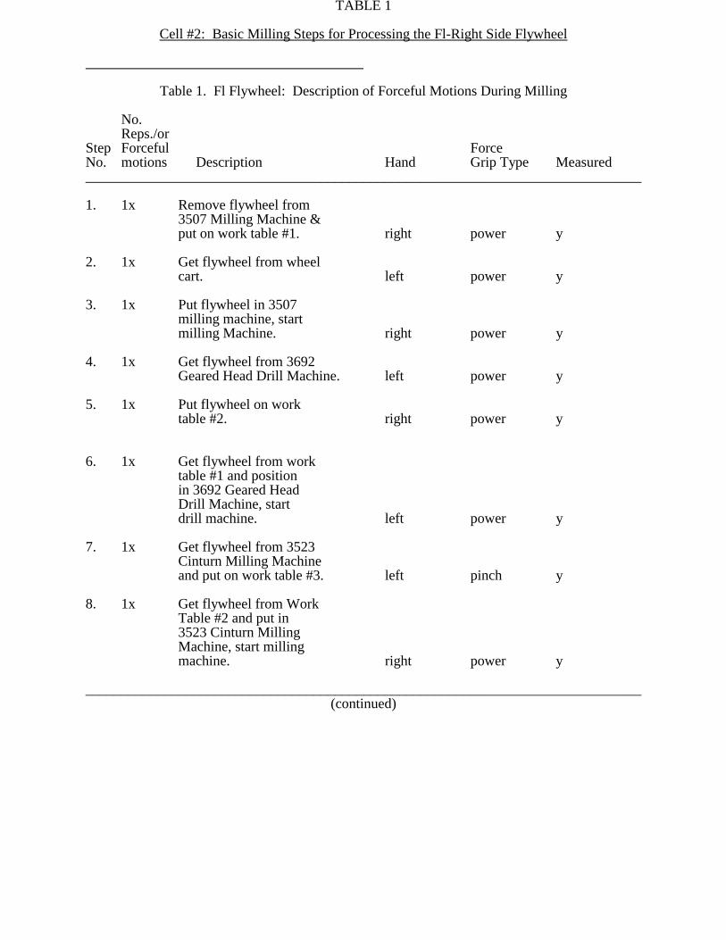
TABLE 1
Cell #2: Basic Milling Steps for Processing the Fl-Right Side Flywheel
Table 1. Fl Flywheel: Description of Forceful Motions During Milling
No.Reps./or
Step Forceful ForceNo. motions Description Hand Grip Type Measured______________________________________________________________________________
1. 1x Remove flywheel from 3507 Milling Machine &put on work table #1. right power y
2. 1x Get flywheel from wheelcart. left power y
3. 1x Put flywheel in 3507 milling machine, startmilling Machine. right power y
4. 1x Get flywheel from 3692 Geared Head Drill Machine. left power y
5. 1x Put flywheel on work table #2. right power y
6. 1x Get flywheel from worktable #1 and position in 3692 Geared Head Drill Machine, startdrill machine. left power y
7. 1x Get flywheel from 3523 Cinturn Milling Machineand put on work table #3. left pinch y
8. 1x Get flywheel from WorkTable #2 and put in 3523 Cinturn MillingMachine, start millingmachine. right power y
______________________________________________________________________________(continued)

TABLE 1 (continued)______________________________________________________________________________
No.Reps./or
Step Forceful ForceNo. motions Description Hand Grip Type Measured______________________________________________________________________________
9. 1x Work Table #3: Hold flywheel (hand used as clamp to hold fly-wheel in place). left pinch
10. 1x Work Table #3: Use power grinder to remove metal burrs. right power
11. 1x Work Table #3: Qualitycontrol check - holdflywheel with handto check. left pinch
12. 1x Work Table #3: Qualitycontrol check - Use calipers to check part. right pinch
13. 1x Position flywheel on work table #3 followingquality control check. right power y
14. 4x Loosen 4 bolts on fly-wheel clamp from 3510 T-10 Machining Center. right power
15. 1x Move flywheel from 3510 Machining Center to Work Table #3. both pinch y
16. 1x Work table #3: Hold flywheel for grindingof metal burrs. left pinch
17. 1x Use power grinder to remove metal burrs. right power
18. 1x Move flywheel to 3510 T-10 Machining Center. left power y
______________________________________________________________________________(continued)
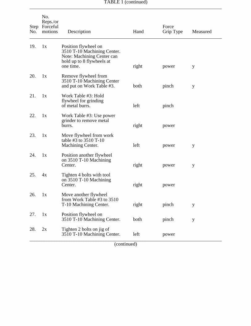
TABLE 1 (continued)______________________________________________________________________________
No.Reps./or
Step Forceful ForceNo. motions Description Hand Grip Type Measured______________________________________________________________________________
19. 1x Position flywheel on3510 T-10 Machining Center.Note: Machining Center canhold up to 8 flywheels atone time. right power y
20. 1x Remove flywheel from 3510 T-10 Machining Centerand put on Work Table #3. both pinch y
21. 1x Work Table #3: Hold flywheel for grindingof metal burrs. left pinch
22. 1x Work Table #3: Use power grinder to remove metal burrs. right power
23. 1x Move flywheel from worktable #3 to 3510 T-10Machining Center. left power y
24. 1x Position another flywheel on 3510 T-10 MachiningCenter. right power y
25. 4x Tighten 4 bolts with toolon 3510 T-10 Machining Center. right power
26. 1x Move another flywheelfrom Work Table #3 to 3510 T-10 Machining Center. right pinch y
27. 1x Position flywheel on 3510 T-10 Machining Center. both pinch y
28. 2x Tighten 2 bolts on jig of 3510 T-10 Machining Center. left power
______________________________________________________________________________(continued)
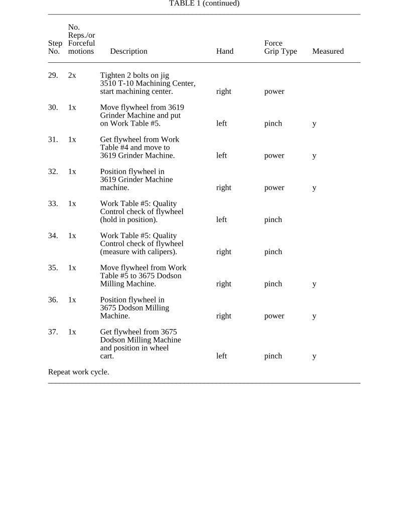
TABLE 1 (continued)______________________________________________________________________________
No.Reps./or
Step Forceful ForceNo. motions Description Hand Grip Type Measured______________________________________________________________________________
29. 2x Tighten 2 bolts on jig 3510 T-10 Machining Center,start machining center. right power
30. 1x Move flywheel from 3619 Grinder Machine and put on Work Table #5. left pinch y
31. 1x Get flywheel from WorkTable #4 and move to 3619 Grinder Machine. left power y
32. 1x Position flywheel in 3619 Grinder Machine machine. right power y
33. 1x Work Table #5: QualityControl check of flywheel(hold in position). left pinch
34. 1x Work Table #5: QualityControl check of flywheel(measure with calipers). right pinch
35. 1x Move flywheel from WorkTable #5 to 3675 DodsonMilling Machine. right pinch y
36. 1x Position flywheel in3675 Dodson Milling Machine. right power y
37. 1x Get flywheel from 3675Dodson Milling Machineand position in wheelcart. left pinch y
Repeat work cycle.______________________________________________________________________________

TABLE 2
Cell #3: Basic Milling Steps for Processing the XL (Both Sides) Flywheel______________________________________________________________________________
Table 2. Xl Flywheel: Description of Forceful Motions During Milling
No.Reps./or
Step Forceful ForceNo. motions Description Hand Grip Type Measured______________________________________________________________________________
1. 1x Remove flywheel from 2819 Sheldon Latheand set on Sheldon Lathetray. right power y
2. 1x Get flywheel from flywheel cart. left pinch y
3. 1x Position flywheel in 2819 Sheldon Lathe, start lathe. right power y
4. 1x Remove flywheel from3539 Special Drill Unitand position on worktable #1. right power y
4. 1x Move flywheel to 3539
Special Drill Unit. right power y
5. 1x Position flywheel in 3539 Special Drill Unit, start drill unit. left power y
6. 1x Move flywheel from worktable #1 to work table #2. left pinch y
7. 1x Remove flywheel from 3521 Cinturn and position onwork table #1. right power y
7. 1x Move flywheel from worktable #2 to 3521 Cinturn. left power y
______________________________________________________________________________(continued)
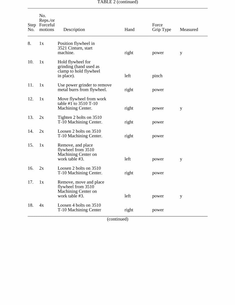
TABLE 2 (continued)______________________________________________________________________________
No.Reps./or
Step Forceful ForceNo. motions Description Hand Grip Type Measured______________________________________________________________________________
8. 1x Position flywheel in3521 Cinturn, start machine. right power y
10. 1x Hold flywheel for grinding (hand used as clamp to hold flywheelin place). left pinch
11. 1x Use power grinder to removemetal burrs from flywheel. right power
12. 1x Move flywheel from worktable #1 to 3510 T-10Machining Center. right power y
13. 2x Tighten 2 bolts on 3510T-10 Machining Center. right power
14. 2x Loosen 2 bolts on 3510T-10 Machining Center. right power
15. 1x Remove, and place flywheel from 3510 Machining Center on work table #3. left power y
16. 2x Loosen 2 bolts on 3510T-10 Machining Center. right power
17. 1x Remove, move and place flywheel from 3510 Machining Center on work table #3. left power y
18. 4x Loosen 4 bolts on 3510T-10 Machining Center right power
______________________________________________________________________________(continued)
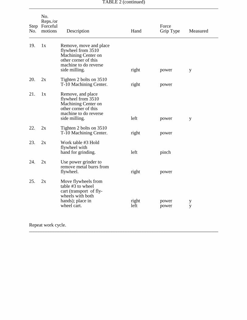
TABLE 2 (continued)______________________________________________________________________________
No.Reps./or
Step Forceful ForceNo. motions Description Hand Grip Type Measured______________________________________________________________________________
19. 1x Remove, move and place flywheel from 3510 Machining Center on other corner of thismachine to do reverseside milling. right power y
20. 2x Tighten 2 bolts on 3510T-10 Machining Center. right power
21. 1x Remove, and place flywheel from 3510 Machining Center on other corner of thismachine to do reverseside milling. left power y
22. 2x Tighten 2 bolts on 3510T-10 Machining Center. right power
23. 2x Work table #3 Hold flywheel withhand for grinding. left pinch
24. 2x Use power grinder to remove metal burrs from flywheel. right power
25. 2x Move flywheels fromtable #3 to wheel cart (transport of fly-wheels with bothhands); place in right power ywheel cart. left power y
Repeat work cycle.______________________________________________________________________________
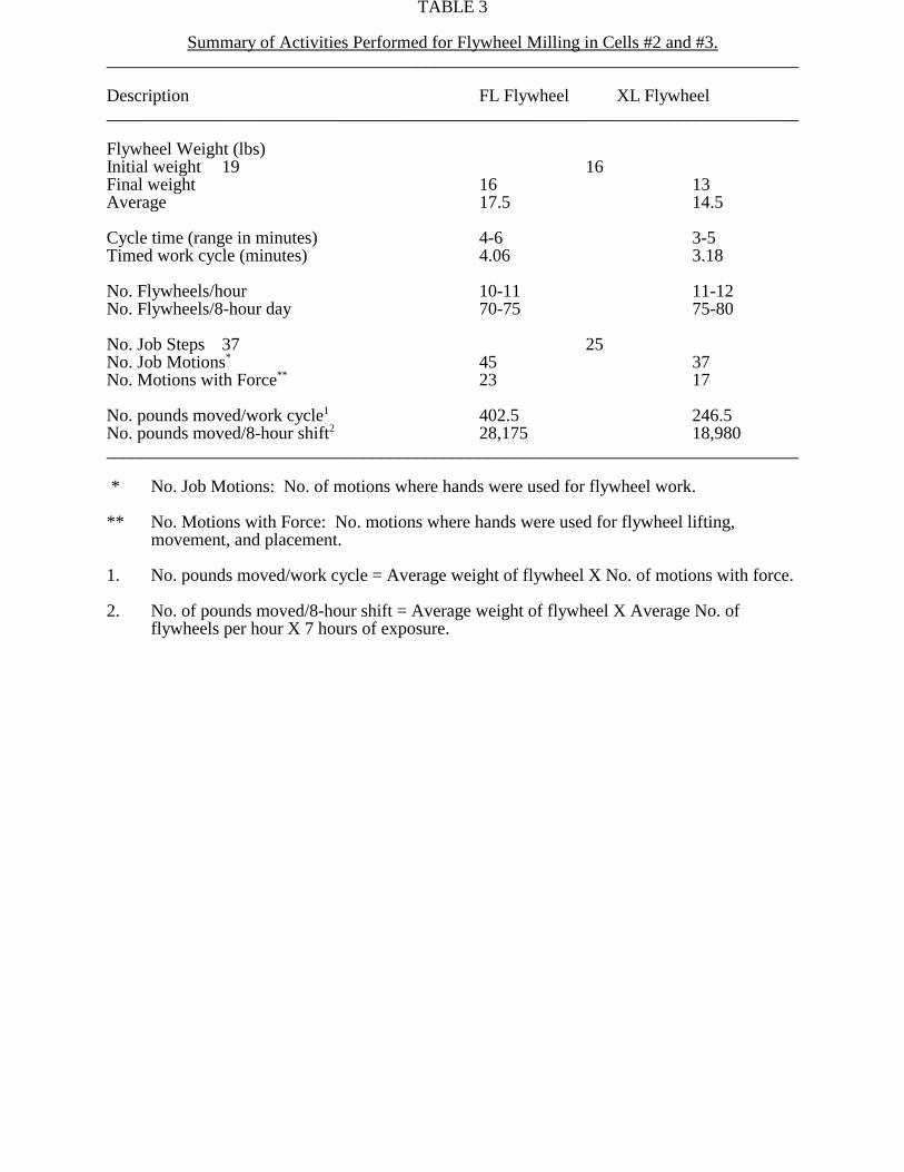
TABLE 3
Summary of Activities Performed for Flywheel Milling in Cells #2 and #3.______________________________________________________________________________
Description FL Flywheel XL Flywheel______________________________________________________________________________
Flywheel Weight (lbs)Initial weight 19 16Final weight 16 13Average 17.5 14.5
Cycle time (range in minutes) 4-6 3-5Timed work cycle (minutes) 4.06 3.18
No. Flywheels/hour 10-11 11-12No. Flywheels/8-hour day 70-75 75-80
No. Job Steps 37 25No. Job Motions* 45 37No. Motions with Force** 23 17
No. pounds moved/work cycle1 402.5 246.5No. pounds moved/8-hour shift2 28,175 18,980______________________________________________________________________________
* No. Job Motions: No. of motions where hands were used for flywheel work.
** No. Motions with Force: No. motions where hands were used for flywheel lifting,movement, and placement.
1. No. pounds moved/work cycle = Average weight of flywheel X No. of motions with force.
2. No. of pounds moved/8-hour shift = Average weight of flywheel X Average No. offlywheels per hour X 7 hours of exposure.
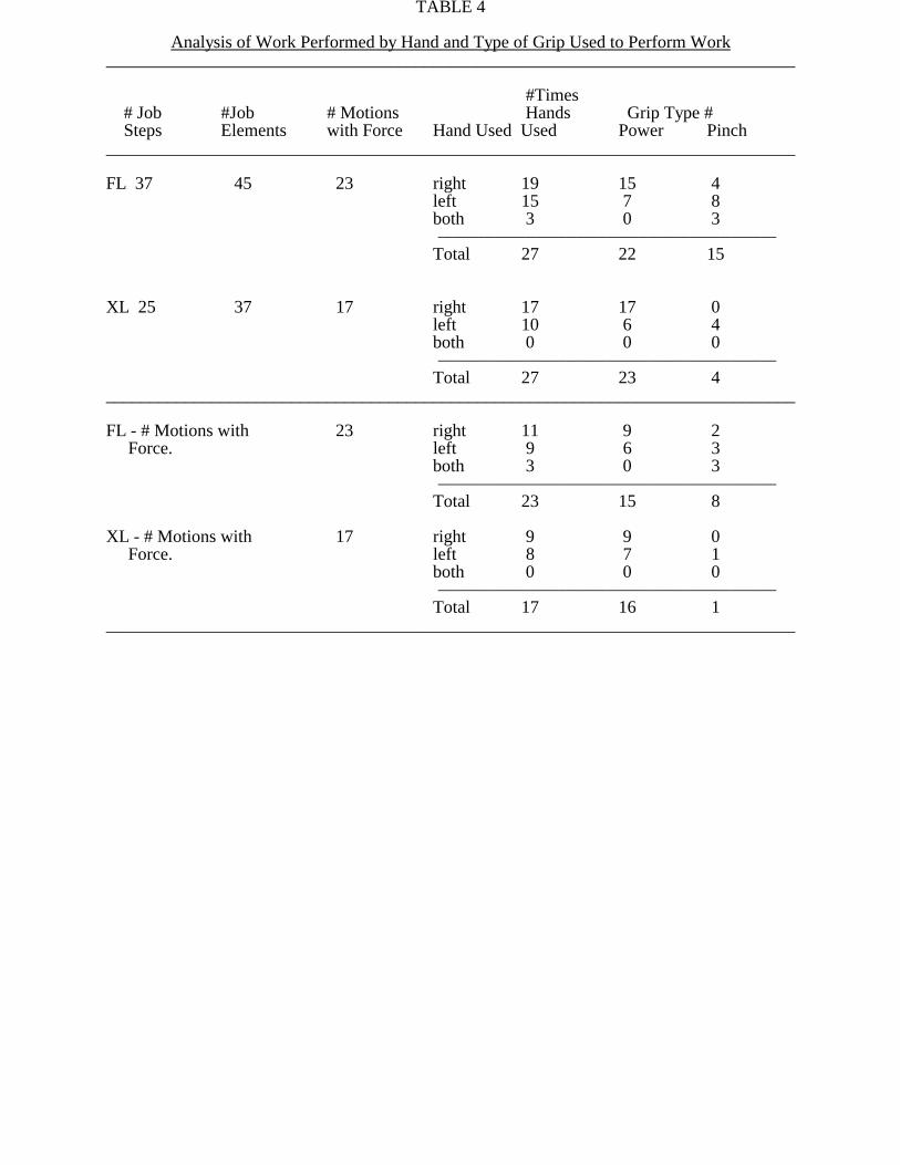
TABLE 4
Analysis of Work Performed by Hand and Type of Grip Used to Perform Work______________________________________________________________________________
#Times # Job #Job # Motions Hands Grip Type # Steps Elements with Force Hand Used Used Power Pinch______________________________________________________________________________
FL 37 45 23 right 19 15 4left 15 7 8both 3 0 3S))))))))))))))))))))))))))))))))Q
Total 27 22 15
XL 25 37 17 right 17 17 0left 10 6 4both 0 0 0S))))))))))))))))))))))))))))))))Q
Total 27 23 4______________________________________________________________________________
FL - # Motions with 23 right 11 9 2 Force. left 9 6 3
both 3 0 3S))))))))))))))))))))))))))))))))Q
Total 23 15 8
XL - # Motions with 17 right 9 9 0 Force. left 8 7 1
both 0 0 0S))))))))))))))))))))))))))))))))Q
Total 17 16 1______________________________________________________________________________

TABLE 5______________________________________________________________________________
ReferenceStep #'sfromTable 1. Problem Recommendation______________________________________________________________________________
2. Reaching and pulling fly- Stack parts in cart by using pre- wheel from cart; pinch grip formed plastic separators; use in handling part; excessive to 2 hands to handle flywheel;
forces in materials handling, reduce reach for flywheelespecially for break away by orienting parts toward workerforces when flywheels are and moving cart closer to 3507jammed in cart. milling machine.
1,3 Excessive asymmetric loading Reduce reach distance by standing
of right upper limb to closer to machine and use twoposition flywheel into hands to position flywheel.3507 milling machine. Loads lifted asymmetrically can import complex and potentiallyhazardous stresses to the lumbar spine.
4,6. Excessive biomechanical loading Minimize reach requirements of upper limbs and back for placing flywheel in the when placing flywheel in 3692 drill machine by removing Geared Head Drill machine. obstacles between machine
and the worker.Example: Relocate palm buttonscloser to drill head.
7,15, Pinch grip, while lifting & Use a power grip whenever20,26, moving flywheel. Pinch grip possible because of superior30,37, requires more muscle strength biomechanical leverage; use35. which stresses the hand tendons material handling devices such
and is more fatiguing than the as gravity conveyors and pushpower grip. wheel carts, where possible.
9,16, Static holding work. Left hand Fabricate a jig or clamp to hold21. used as jig or clamp while other the flywheel. The jig should
hand is used to operate grinder. be easily rotated, such as on ball barring, to easily access all areas of flywheelfor metal grinding.
______________________________________________________________________________(continued)
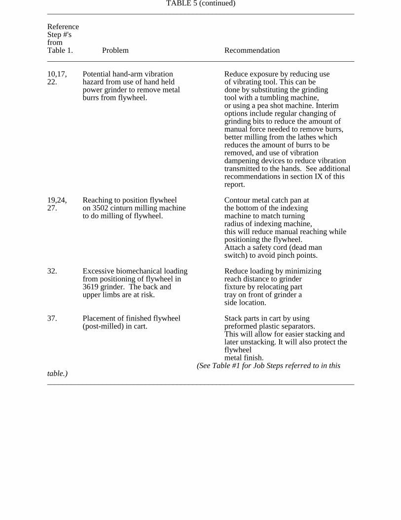
TABLE 5 (continued)______________________________________________________________________________
ReferenceStep #'sfromTable 1. Problem Recommendation______________________________________________________________________________
10,17, Potential hand-arm vibration Reduce exposure by reducing use22. hazard from use of hand held of vibrating tool. This can be
power grinder to remove metal done by substituting the grindingburrs from flywheel. tool with a tumbling machine,
or using a pea shot machine. Interimoptions include regular changing ofgrinding bits to reduce the amount ofmanual force needed to remove burrs,better milling from the lathes whichreduces the amount of burrs to beremoved, and use of vibrationdampening devices to reduce vibrationtransmitted to the hands. See additionalrecommendations in section IX of thisreport.
19,24, Reaching to position flywheel Contour metal catch pan at27. on 3502 cinturn milling machine the bottom of the indexing
to do milling of flywheel. machine to match turning radius of indexing machine,this will reduce manual reaching whilepositioning the flywheel.Attach a safety cord (dead manswitch) to avoid pinch points.
32. Excessive biomechanical loading Reduce loading by minimizingfrom positioning of flywheel in reach distance to grinder 3619 grinder. The back and fixture by relocating partupper limbs are at risk. tray on front of grinder a
side location.
37. Placement of finished flywheel Stack parts in cart by using(post-milled) in cart. preformed plastic separators.
This will allow for easier stacking andlater unstacking. It will also protect theflywheelmetal finish.
(See Table #1 for Job Steps referred to in thistable.)______________________________________________________________________________

TABLE 6______________________________________________________________________________
ReferenceStep #'sfromTable 2 Problem Recommendation______________________________________________________________________________
2. Reaching and pulling fly- Stack parts in cart by using pre- wheel from wheel cart; pinch formed plastic separators; use 2 grip in handling part; excessive hands to handle flywheel; reduceforces in materials handling; reach and flywheel handlingespecially for break away forces by orienting parts toward workerwhen flywheels are jammed in cart. and moving cart closer to milling
machine. 5. Positioning flywheel in Handle part with both hands
3539 Special Drill unit with one when positioning flywheel hand causes excess asymmetric in drill unit; minimize reach
biomechanical mechanical loading distances by standing as closeon the shoulder. to the drill unit as possible.
Relocate obstacles to stand closer to the drill unit.
6. Awkward handling of flywheel Reduce biomechanical stressmay cause excessive on upper limbs by handlingbiomechanical stress on upper part with two hands, uselimbs, especially to the hands wheel-carts or conveyors (whereand wrists. possible) to move flywheels
from one machine to another; use power grip (handle flywheel by itsspindle and balance load while handling.
11,24. Use of powered hand grinder Reduce exposure by reducing useto remove metal burrs from of tool. Better milling fromflywheel may cause hand and sharper lathe blades shouldarm vibration related disorders. reduce the time and amount of grinding
of metal burrs. A tumbling machine, orpea shot should also be considered forremoval of metal burrs.
______________________________________________________________________________(continued)
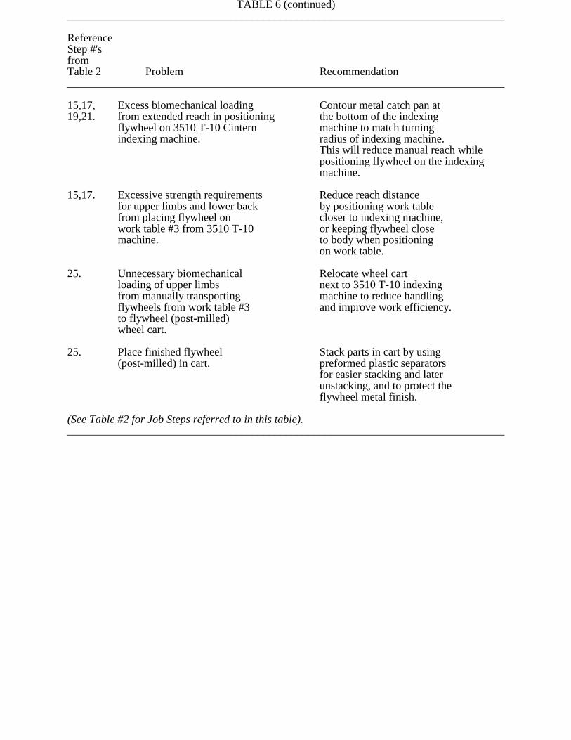
TABLE 6 (continued)______________________________________________________________________________
ReferenceStep #'sfromTable 2 Problem Recommendation______________________________________________________________________________
15,17, Excess biomechanical loading Contour metal catch pan at 19,21. from extended reach in positioning the bottom of the indexing
flywheel on 3510 T-10 Cintern machine to match turningindexing machine. radius of indexing machine.
This will reduce manual reach whilepositioning flywheel on the indexingmachine.
15,17. Excessive strength requirements Reduce reach distance for upper limbs and lower back by positioning work table from placing flywheel on closer to indexing machine,work table #3 from 3510 T-10 or keeping flywheel closemachine. to body when positioning on work table.
25. Unnecessary biomechanical Relocate wheel cart loading of upper limbs next to 3510 T-10 indexing from manually transporting machine to reduce handlingflywheels from work table #3 and improve work efficiency.to flywheel (post-milled)wheel cart.
25. Place finished flywheel Stack parts in cart by using(post-milled) in cart. preformed plastic separators
for easier stacking and laterunstacking, and to protect theflywheel metal finish.
(See Table #2 for Job Steps referred to in this table).______________________________________________________________________________