HERON/HAYMANbbp.style/PUBLIC/products/technical-information/austral...driveway, house, fence or...
18
HERON/HAYMAN retaining walls installation guide OCTOBER 2016
Transcript of HERON/HAYMANbbp.style/PUBLIC/products/technical-information/austral...driveway, house, fence or...
HERON/HAYMANretaining walls installation guide
OCTOBER 2016
RETAINING WALL INSTALLATION GUIDE
RETAINING WALLinformation
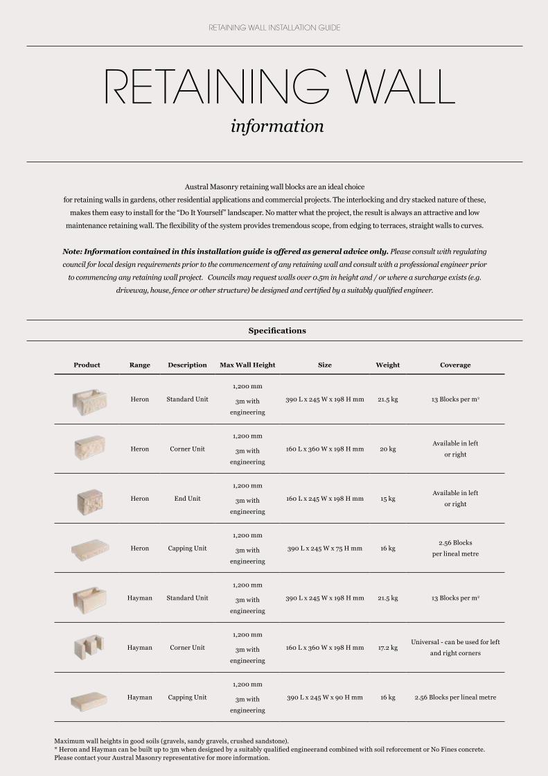
Maximum wall heights in good soils (gravels, sandy gravels, crushed sandstone). * Heron and Hayman can be built up to 3m when designed by a suitably qualified engineerand combined with soil reforcement or No Fines concrete. Please contact your Austral Masonry representative for more information.
Product Range Description Max Wall Height Size Weight Coverage
Heron Standard Unit
1,200 mm
3m with
engineering
390 L x 245 W x 198 H mm 21.5 kg 13 Blocks per m2
Heron Corner Unit
1,200 mm
3m with
engineering
160 L x 360 W x 198 H mm 20 kgAvailable in left
or right
Heron End Unit
1,200 mm
3m with
engineering
160 L x 245 W x 198 H mm 15 kgAvailable in left
or right
Heron Capping Unit
1,200 mm
3m with
engineering
390 L x 245 W x 75 H mm 16 kg2.56 Blocks
per lineal metre
Hayman Standard Unit
1,200 mm
3m with
engineering
390 L x 245 W x 198 H mm 21.5 kg 13 Blocks per m2
Hayman Corner Unit
1,200 mm
3m with
engineering
160 L x 360 W x 198 H mm 17.2 kgUniversal - can be used for left
and right corners
Hayman Capping Unit
1,200 mm
3m with
engineering
390 L x 245 W x 90 H mm 16 kg 2.56 Blocks per lineal metre
Specifications
Austral Masonry retaining wall blocks are an ideal choice
for retaining walls in gardens, other residential applications and commercial projects. The interlocking and dry stacked nature of these,
makes them easy to install for the “Do It Yourself” landscaper. No matter what the project, the result is always an attractive and low
maintenance retaining wall. The flexibility of the system provides tremendous scope, from edging to terraces, straight walls to curves.
Note: Information contained in this installation guide is offered as general advice only. Please consult with regulating
council for local design requirements prior to the commencement of any retaining wall and consult with a professional engineer prior
to commencing any retaining wall project. Councils may request walls over 0.5m in height and / or where a surcharge exists (e.g.
driveway, house, fence or other structure) be designed and certified by a suitably qualified engineer.
/ 3 /
HERON/HAYMAN
Maximum wall heights in good soils (gravels, sandy gravels, crushed sandstone). * Heron and Hayman can be built up to 3m when designed by a suitably qualified engineerand combined with soil reforcement or No Fines concrete. Please contact your Austral Masonry representative for more information.
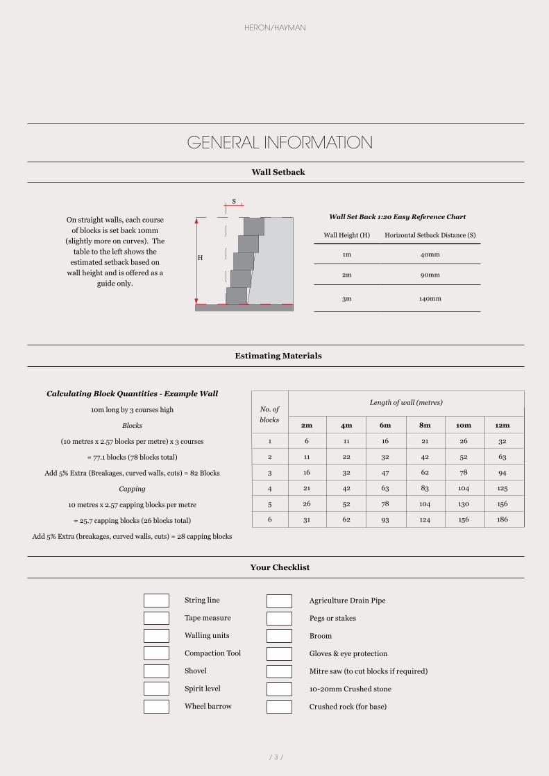
Wall Set Back 1:20 Easy Reference Chart
Wall Height (H) Horizontal Setback Distance (S)
1m 40mm
2m 90mm
3m 140mm
On straight walls, each course of blocks is set back 10mm
(slightly more on curves). The table to the left shows the
estimated setback based on wall height and is offered as a
guide only.
Calculating Block Quantities - Example Wall
10m long by 3 courses high
Blocks
(10 metres x 2.57 blocks per metre) x 3 courses
= 77.1 blocks (78 blocks total)
Add 5% Extra (Breakages, curved walls, cuts) = 82 Blocks
Capping
10 metres x 2.57 capping blocks per metre
= 25.7 capping blocks (26 blocks total)
Add 5% Extra (breakages, curved walls, cuts) = 28 capping blocks
GENERAL INFORMATION
Wall Setback
Estimating Materials
H
S
2m 4m 6m 8m 10m 12m
1 6 11 16 21 26 32
2 11 22 32 42 52 63
3 16 32 47 62 78 94
4 21 42 63 83 104 125
5 26 52 78 104 130 156
6 31 62 93 124 156 186
Length of wall (metres)No. of blocks
Your Checklist
String line
Tape measure
Walling units
Compaction Tool
Shovel
Spirit level
Wheel barrow
Agriculture Drain Pipe
Pegs or stakes
Broom
Gloves & eye protection
Mitre saw (to cut blocks if required)
10-20mm Crushed stone
Crushed rock (for base)
/ 4 /
RETAINING WALL INSTALLATION GUIDE
SOIL REINFORCED WALLS WITH GEOGRID
Austral Masonry’s Heron segmental block retaining wall system utilizes its shape and weight in order to resist the lateral earth pressures. In combination with geogrid soil reinforcement, these walls can be built to substantial heights, without costly structural reinforced concrete footings.
The length, location and grade strength of geogrid is dependent on the wall height, loading on top of the structure, and soil properties.
The following table is in accordance with AS4678: 2002 - Earth Retaining Structures.
Note: Please consult with appropriate council for design and construction regulations. Councils in general require walls to be designed and certified by a suitably qualified engineer where the wall is over 500mm in
height or will have a surcharge load such as a road, building or hydrostatic pressure is present. The suitability of the information contained in the table must be referred to a qualified consulting engineer. These tables are
provided as a guide only.
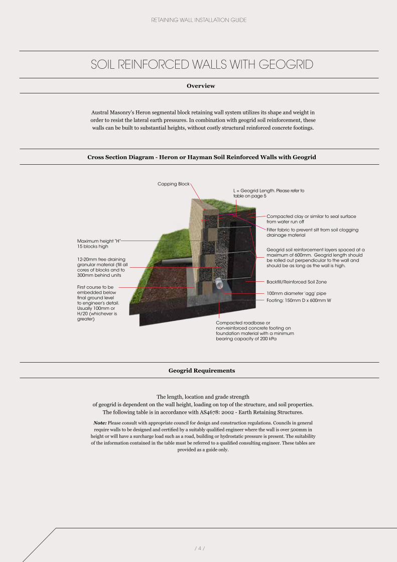
Cross Section Diagram - Heron or Hayman Soil Reinforced Walls with Geogrid
Geogrid Requirements
Overview
Backfill/Reinforced Soil Zone
100mm diameter ‘agg’ pipeFirst course to be embedded below final ground level to engineer’s detail. Usually 100mm or H/20 (whichever is greater)
Maximum height “H”15 blocks high
Geogrid soil reinforcement layers spaced at a maximum of 600mm. Geogrid length should be rolled out perpendicular to the wall and should be as long as the wall is high.
Compacted clay or similar to seal surface from water run off
Filter fabric to prevent silt from soil clogging drainage material
12-20mm free draining granular material (fill all cores of blocks and to 300mm behind units
Capping BlockL = Geogrid Length. Please refer to table on page 5
Compacted roadbase or non-reinforced concrete footing on foundation material with a minimum bearing capacity of 200 kPa
Footing: 150mm D x 600mm W
/ 5 /
HERON/HAYMAN
- Maximum wall heights table is based on a 5kPa surcharge load acting on top of the wall as per AS4678: 2002. This table is supplied as a guide only and must be referred to a qualified
professional engineer. If imposed surcharge loads above 5kPa are applied, these designs are not appropriate.
- The Table above assumes the foundation material has a minimum bearing capacity of 200kPa.
- Designs assume no hydrostatic loading.
- The minimum embedment of wall below ground level is assumed to be the greater of H/20 or 100mm.
- Designs are based on Geogrid strength of 55kN/m2
• Poor (Ø = 250): Soils with friction angle > 250, may include sandy clays, gravelly clays and sand. Expansive clays and organic soil MUST not be used within the soil reinforced zone.
• Average (Ø = 300): Soils with friction angle > 300, may include gravelly sands and well graded sands.
• Good (Ø = 350): Soils with friction angle >350, may include gravels, sandy gravels, weathered sandstone and crushed sandstone.
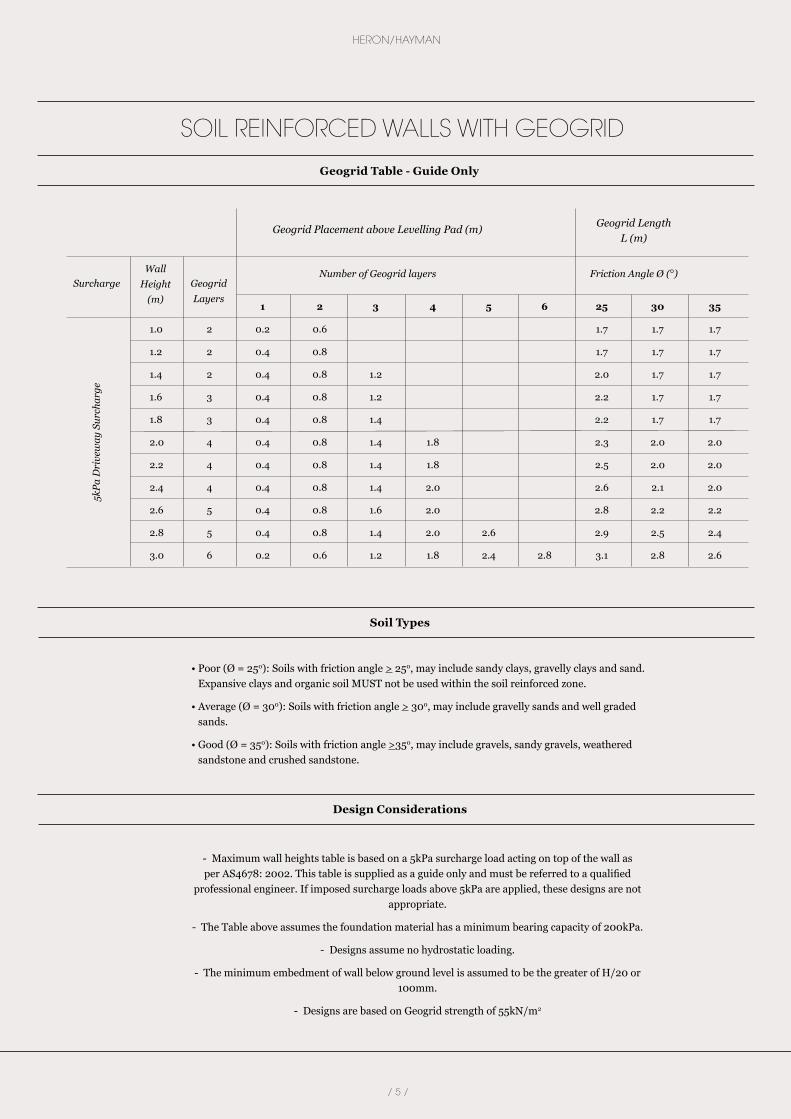
1 2 3 4 5 6 25 30 35
1.0 2 0.2 0.6 1.7 1.7 1.7
1.2 2 0.4 0.8 1.7 1.7 1.7
1.4 2 0.4 0.8 1.2 2.0 1.7 1.7
1.6 3 0.4 0.8 1.2 2.2 1.7 1.7
1.8 3 0.4 0.8 1.4 2.2 1.7 1.7
2.0 4 0.4 0.8 1.4 1.8 2.3 2.0 2.0
2.2 4 0.4 0.8 1.4 1.8 2.5 2.0 2.0
2.4 4 0.4 0.8 1.4 2.0 2.6 2.1 2.0
2.6 5 0.4 0.8 1.6 2.0 2.8 2.2 2.2
2.8 5 0.4 0.8 1.4 2.0 2.6 2.9 2.5 2.4
3.0 6 0.2 0.6 1.2 1.8 2.4 2.8 3.1 2.8 2.6
Geogrid Placement above Levelling Pad (m)
5kPa
Dri
vew
ay S
urch
arge
Number of Geogrid layers Friction Angle Ø (º)
Geogrid Length L (m)
Geogrid Layers
Wall Height
(m)
Surcharge
SOIL REINFORCED WALLS WITH GEOGRID
Geogrid Table - Guide Only
Soil Types
Design Considerations
/ 6 /
RETAINING WALL INSTALLATION GUIDE
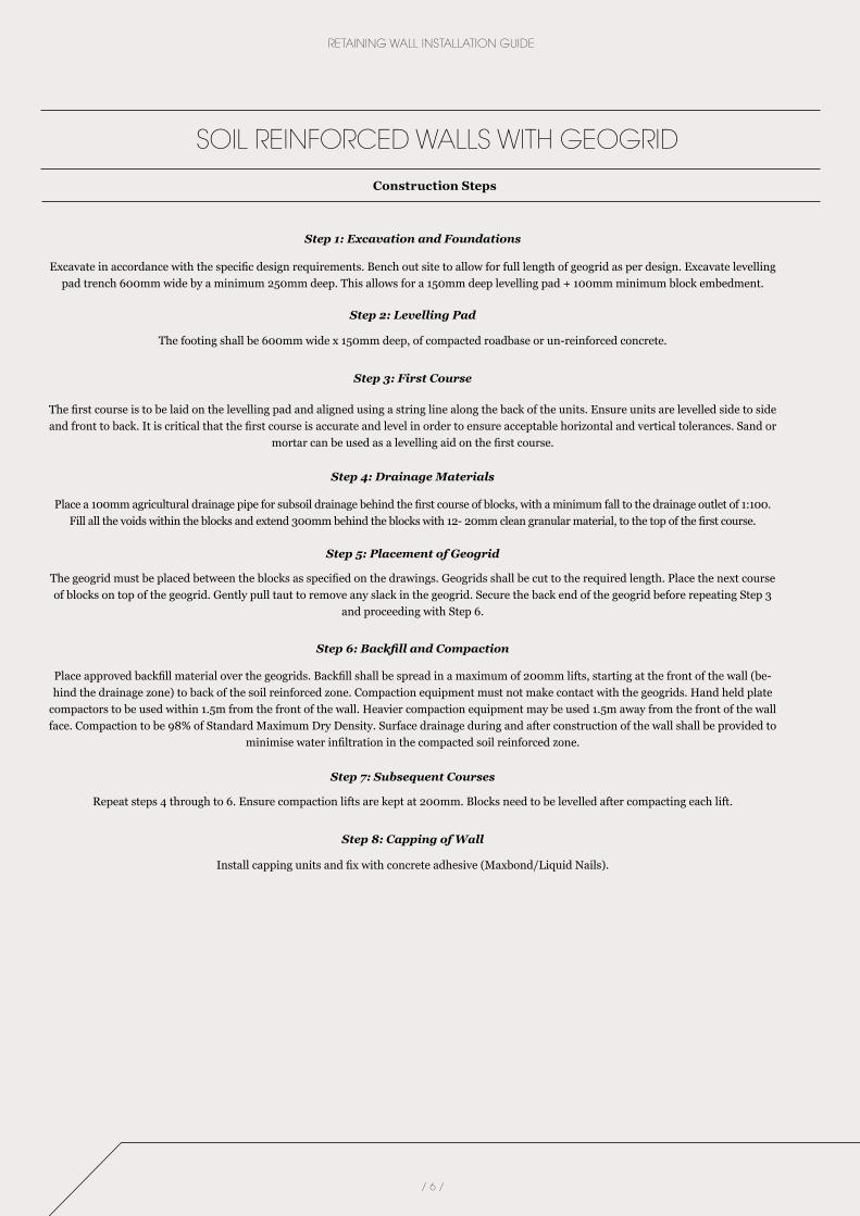
Step 1: Excavation and Foundations
Excavate in accordance with the specific design requirements. Bench out site to allow for full length of geogrid as per design. Excavate levelling pad trench 600mm wide by a minimum 250mm deep. This allows for a 150mm deep levelling pad + 100mm minimum block embedment.
Step 2: Levelling Pad
The footing shall be 600mm wide x 150mm deep, of compacted roadbase or un-reinforced concrete.
Step 3: First Course
The first course is to be laid on the levelling pad and aligned using a string line along the back of the units. Ensure units are levelled side to side and front to back. It is critical that the first course is accurate and level in order to ensure acceptable horizontal and vertical tolerances. Sand or
mortar can be used as a levelling aid on the first course.
Step 4: Drainage Materials
Place a 100mm agricultural drainage pipe for subsoil drainage behind the first course of blocks, with a minimum fall to the drainage outlet of 1:100. Fill all the voids within the blocks and extend 300mm behind the blocks with 12- 20mm clean granular material, to the top of the first course.
Step 5: Placement of Geogrid
The geogrid must be placed between the blocks as specified on the drawings. Geogrids shall be cut to the required length. Place the next course of blocks on top of the geogrid. Gently pull taut to remove any slack in the geogrid. Secure the back end of the geogrid before repeating Step 3
and proceeding with Step 6.
Step 6: Backfill and Compaction
Place approved backfill material over the geogrids. Backfill shall be spread in a maximum of 200mm lifts, starting at the front of the wall (be-hind the drainage zone) to back of the soil reinforced zone. Compaction equipment must not make contact with the geogrids. Hand held plate
compactors to be used within 1.5m from the front of the wall. Heavier compaction equipment may be used 1.5m away from the front of the wall face. Compaction to be 98% of Standard Maximum Dry Density. Surface drainage during and after construction of the wall shall be provided to
minimise water infiltration in the compacted soil reinforced zone.
Step 7: Subsequent Courses
Repeat steps 4 through to 6. Ensure compaction lifts are kept at 200mm. Blocks need to be levelled after compacting each lift.
Step 8: Capping of Wall
Install capping units and fix with concrete adhesive (Maxbond/Liquid Nails).
SOIL REINFORCED WALLS WITH GEOGRID
Construction Steps
/ 7 /
HERON/HAYMAN
/ 8 /
RETAINING WALL INSTALLATION GUIDE
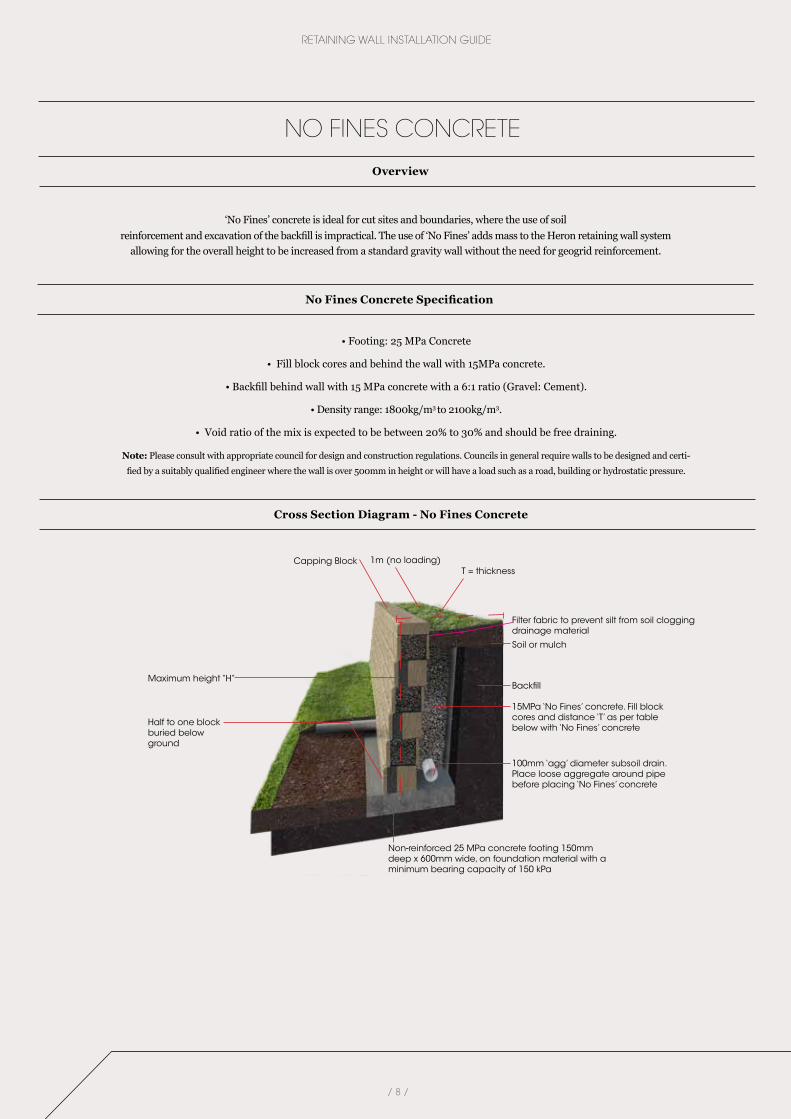
‘No Fines’ concrete is ideal for cut sites and boundaries, where the use of soil reinforcement and excavation of the backfill is impractical. The use of ‘No Fines’ adds mass to the Heron retaining wall system
allowing for the overall height to be increased from a standard gravity wall without the need for geogrid reinforcement.
NO FINES CONCRETE
Overview
Cross Section Diagram - No Fines Concrete
No Fines Concrete Specification
• Footing: 25 MPa Concrete
• Fill block cores and behind the wall with 15MPa concrete.
• Backfill behind wall with 15 MPa concrete with a 6:1 ratio (Gravel: Cement).
• Density range: 1800kg/m3 to 2100kg/m3.
• Void ratio of the mix is expected to be between 20% to 30% and should be free draining.
Note: Please consult with appropriate council for design and construction regulations. Councils in general require walls to be designed and certi-
fied by a suitably qualified engineer where the wall is over 500mm in height or will have a load such as a road, building or hydrostatic pressure.
Non-reinforced 25 MPa concrete footing 150mm deep x 600mm wide, on foundation material with a minimum bearing capacity of 150 kPa
Backfill
100mm ‘agg’ diameter subsoil drain. Place loose aggregate around pipe before placing ‘No Fines’ concrete
Half to one block buried below ground
Maximum height “H”
15MPa ‘No Fines’ concrete. Fill block cores and distance ‘T’ as per table below with ‘No Fines’ concrete
Soil or mulch
Capping Block 1m (no loading)T = thickness
Filter fabric to prevent silt from soil clogging drainage material
/ 9 /
HERON/HAYMAN
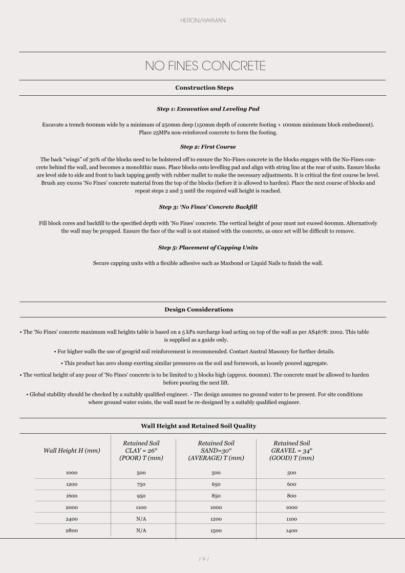
• The ‘No Fines’ concrete maximum wall heights table is based on a 5 kPa surcharge load acting on top of the wall as per AS4678: 2002. This table is supplied as a guide only.
• For higher walls the use of geogrid soil reinforcement is recommended. Contact Austral Masonry for further details.
• This product has zero slump exerting similar pressures on the soil and formwork, as loosely poured aggregate.
• The vertical height of any pour of ‘No Fines’ concrete is to be limited to 3 blocks high (approx. 600mm). The concrete must be allowed to harden before pouring the next lift.
• Global stability should be checked by a suitably qualified engineer. - The design assumes no ground water to be present. For site conditions where ground water exists, the wall must be re-designed by a suitably qualified engineer.
Retained Soil Retained Soil Retained Soil Wall Height H (mm) CLAY = 26° SAND=30° GRAVEL = 34° (POOR) T (mm) (AVERAGE) T (mm) (GOOD) T (mm)
1000 500 500 500
1200 750 650 600
1600 950 850 800
2000 1100 1000 1000
2400 N/A 1200 1100
2800 N/A 1500 1400
Step 1: Excavation and Leveling Pad
Excavate a trench 600mm wide by a minimum of 250mm deep (150mm depth of concrete footing + 100mm minimum block embedment). Place 25MPa non-reinforced concrete to form the footing.
Step 2: First Course
The back “wings” of 30% of the blocks need to be bolstered off to ensure the No-Fines concrete in the blocks engages with the No-Fines con-crete behind the wall, and becomes a monolithic mass. Place blocks onto levelling pad and align with string line at the rear of units. Ensure blocks are level side to side and front to back tapping gently with rubber mallet to make the necessary adjustments. It is critical the first course be level.
Brush any excess ‘No Fines’ concrete material from the top of the blocks (before it is allowed to harden). Place the next course of blocks and repeat steps 2 and 3 until the required wall height is reached.
Step 3: ‘No Fines’ Concrete Backfill
Fill block cores and backfill to the specified depth with ‘No Fines’ concrete. The vertical height of pour must not exceed 600mm. Alternatively the wall may be propped. Ensure the face of the wall is not stained with the concrete, as once set will be difficult to remove.
Step 5: Placement of Capping Units
Secure capping units with a flexible adhesive such as Maxbond or Liquid Nails to finish the wall.
NO FINES CONCRETE
Construction Steps
Wall Height and Retained Soil Quality
Design Considerations
/ 10 /
RETAINING WALL INSTALLATION GUIDE
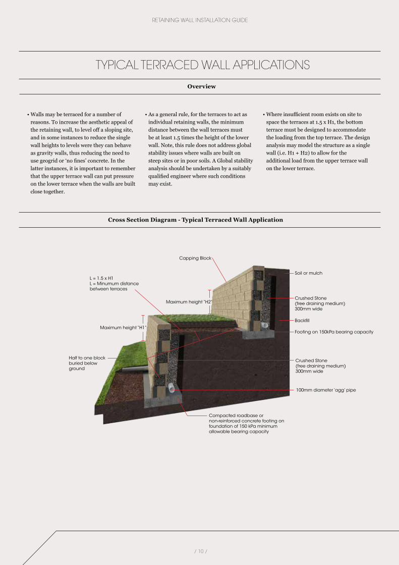
• Walls may be terraced for a number of reasons. To increase the aesthetic appeal of the retaining wall, to level off a sloping site, and in some instances to reduce the single wall heights to levels were they can behave as gravity walls, thus reducing the need to use geogrid or ‘no fines’ concrete. In the latter instances, it is important to remember that the upper terrace wall can put pressure on the lower terrace when the walls are built close together.
• As a general rule, for the terraces to act as individual retaining walls, the minimum distance between the wall terraces must be at least 1.5 times the height of the lower wall. Note, this rule does not address global stability issues where walls are built on steep sites or in poor soils. A Global stability analysis should be undertaken by a suitably qualified engineer where such conditions may exist.
• Where insufficient room exists on site to space the terraces at 1.5 x H1, the bottom terrace must be designed to accommodate the loading from the top terrace. The design analysis may model the structure as a single wall (i.e. H1 + H2) to allow for the additional load from the upper terrace wall on the lower terrace.
TYPICAL TERRACED WALL APPLICATIONS
Overview
Cross Section Diagram - Typical Terraced Wall Application
Backfill
Footing on 150kPa bearing capacity
100mm diameter ‘agg’ pipe
Half to one block buried below ground
Maximum height “H1”
Maximum height “H2”Crushed Stone(free draining medium) 300mm wide
Crushed Stone(free draining medium) 300mm wide
L = 1.5 x H1L = Minumum distance between terraces
Soil or mulch
Capping Block
Compacted roadbase or non-reinforced concrete footing on foundation of 150 kPa minimum allowable bearing capacity
/ 11 /
HERON/HAYMAN
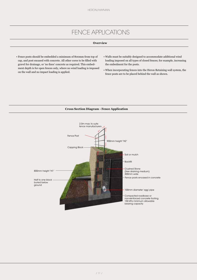
• Fence posts should be embedded a minimum of 800mm from top of cap, and post encased with concrete. All other cores to be filled with gravel for drainage, or ‘no fines’ concrete as required. This embed-ment depth is for open fences only, where no wind loading is imposed on the wall and no impact loading is applied.
• Walls must be suitably designed to accommodate additional wind loading imposed on all types of closed fences; for example, increasing the embedment for the posts.
• When incorporating fences into the Heron Retaining wall system, the fence posts are to be placed behind the wall as shown.
FENCE APPLICATIONS
Overview
Cross Section Diagram - Fence Application
Compacted roadbase or non-reinforced concrete footing. 150 kPa minimum allowable bearing capacity
Backfill
100mm diameter ‘agg’ pipe
Half to one block buried below ground
800mm height “H1”Crushed Stone(free draining medium) 300mm wide
Fence posts encased in concrete
Soil or mulch
Capping Block
Fence Post
900mm height “H2”
2.0m max. to suite fence manufacturers

/ 12 /
RETAINING WALL INSTALLATION GUIDE
245mm
245mm
145mm
145mm
390mm
390mm
Standard 90º Corner Layout
Heron End Unit
Heron Standard Unit
Heron Standard UnitHeron Corner Unit
Detail for Stepping Down Blocks
STRAIGHT CORNERS
Laying Information - Standard 90º Corner Layout/Step Down on Top of Wall
Capping Layout for 90º Corner
/ 13 /
HERON/HAYMAN
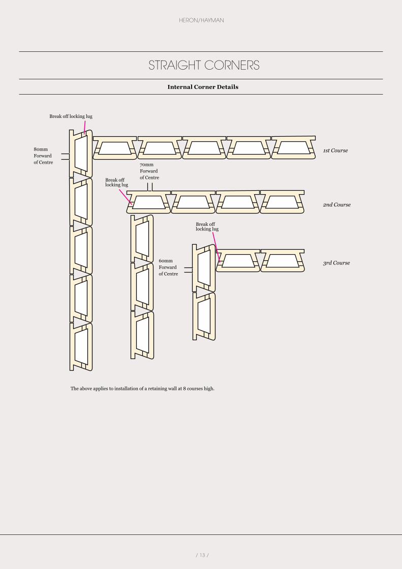
Heron End Unit80mm Forward of Centre
60mm Forward of Centre
The above applies to installation of a retaining wall at 8 courses high.
70mm Forward of Centre
Break off locking lug
Break off locking lug
Break off locking lug
1st Course
2nd Course
3rd Course
STRAIGHT CORNERS
Internal Corner Details
/ 14 /
RETAINING WALL INSTALLATION GUIDE
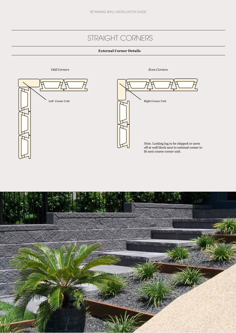
Odd Corners Even Corners
Left Corner Unit Right Corner Unit
STRAIGHT CORNERS
External Corner Details
Note. Locking lug to be chipped or sawn off at wall block next to external corner to fit next course corner unit.

/ 15 /
HERON/HAYMAN
CURVED CORNERS
Block Preparation - Remove Block ‘Wings’
Block Preparation - Remove Locking Lugs for External Corners
The Heron and Hayman blocks have been designed with ‘wings’ on either side that can be removed when constructing curved walls. Simply use a hammer or mallet to knock these off as required.
Using a hammer or mallet, knock off one concrete nib to fit next course corner unit.
Locking Lugs
Straight Walls leading to Curved Sections
Heron and Hayman blocks can be used to create circular walls with ease. Make sure to plan out the laying of the blocks by plotting the first course before getting started. Pay careful attention to spacing of the blocks as you lay them to ensure the circles angle allows full blocks to
be laid around the circumference of the wall.
Block ‘Wings’
Right Corner Unit
Standard Unit withwings removed
Standard Unit withwings removed
1st Course
2nd Course
/ 16 /
RETAINING WALL INSTALLATION GUIDE
CURVED WALLS
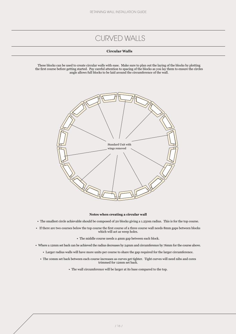
These blocks can be used to create circular walls with ease. Make sure to plan out the laying of the blocks by plotting the first course before getting started. Pay careful attention to spacing of the blocks as you lay them to ensure the circles
angle allows full blocks to be laid around the circumference of the wall.
Notes when creating a circular wall
• The smallest circle achievable should be composed of 20 blocks giving a 1.250m radius. This is for the top course.
• If there are two courses below the top course the first course of a three course wall needs 8mm gaps between blocks which will act as weep holes.
• The middle course needs a 4mm gap between each block.
• Where a 12mm set back can be achieved the radius decreases by 24mm and circumference by 76mm for the course above.
• Larger radius walls will have more units per course to share the gap required for the larger circumference.
• The 10mm set back between each course increases as curves get tighter. Tight curves will need nibs and cores trimmed for 12mm set back.
• The wall circumference will be larger at its base compared to the top.
Circular Walls
Standard Unit withwings removed
/ 17 /
HERON/HAYMAN
CURVED WALLS
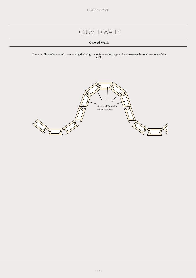
Curved walls can be created by removing the ‘wings’ as referenced on page 15 for the external curved sections of the wall.
Curved Walls
Standard Unit withwings removed

The product images in our brochures give a general indication of colour for your preliminary selection.
follow brickworks building products on
Partners in Design 08/2016
Austral Bricks is part of the Brickworks Group
Proud Supporters
NATIONAL HEAD OFFICES
Austral Masonry is part of the Brickworks Group1. Stock colours.
minimum quantity. 2. Colour and texture variation. The supply of raw materials can vary over time. In addition, variation can occur between product types and production batches. 3. We reserve the right to change the details in this publication without notice. 4. 5. Important Notice. Please consult with your local council for design regulations prior to the construction of your wall. Councils in general require those walls over 0.5m in height and/or where
6. Max wall heights disclaimer. The gravity wall heights are maximum heights
The product images shown in this brochure give a general indication of product colour for your preliminary selection. Austral Masonry recommends all customers see actual product samples at
Partners In Design 06/2016
STYLE AND FUNCTION
www.australmasonry.com.au
1300 masonry (1300 627 667)
Gympie
Cnr Woondum Rd and Bruce Highway Gympie QLD 4570Tel: (07) 5489 6900 E: [email protected]
Queensland
184 Burnside Rd Yatala QLD 4208Tel: (07) 3441 7500 Fax: (07) 3807 0954 E: [email protected]
New South Wales
44 Clunies Ross St Prospect NSW 2148Tel: (02) 9840 2333 Fax: (02) 9840 2344 E: [email protected]
Victoria
Brickmakers Drive Wollert VIC 3750Tel: (03) 9303 4000 Fax: (03) 9308 1974 E: [email protected]
STYLE AND FUNCTION
www.australmasonry.com.au1300 masonry (1300 627 667)
follow brickworks building products on
Partners in Design 09/2016