INSTALLATION INSTRUCTIONS 8500 / 12-8500 / AD8500 Narrow ...

990-451 REV E
HERMETIC SEALING SYSTEM
AF-8500/1250
OPERATION MANUAL

AF-8500 / 1250 Autoflow User Guide
2 990-451
Copyright © 2011 - 2016 Amada Miyachi America Corporation
The engineering designs, drawings and data contained herein are the proprietary work of Amada Miyachi America Corporation and may not be reproduced, copied, exhibited or otherwise used without the written authorization of Amada Miyachi America Corporation.
Printed in the United States of America.
Revision Record
Rev ECO Date Basis of Revision
001 None 09/09 Initial Release
002 None 03/10 Add buttons in Jog Mode for Auer Boat elevator options.
003 None 06/10 Add Lid Pickup Options in Jog Mode, Add Seal Ring size option,Add large part support.
004 None 08/10 Add support for AF8500.
A 40530 01/11 Incorporated into Miyachi Unitek documents.
B 42840 01/11 Updated to Miyachi America name and logo.
C 43480 12/14 Updated to Amada Miyachi America name and logo.
D 43838 08/15 Updated to Amada Miyachi format.
E 44060 10/16 Updated Screen Images to Windows 7 (64‐bit) + added functions.

AF-8500 / 1250 Autoflow User Guide
990-451 3
FOREWORD
The purpose of this manual is to supply operating, maintenance and service personnel with the information needed to operate the Autoflow welding system.
Should questions arise, or if you have suggestions for improving this manual, please contact:
Amada Miyachi America, Inc. 1820 South Myrtle Avenue Monrovia, CA 91016
Telephone: (626) 303‐5676
FAX: (626) 358‐8048
E‐Mail: [email protected]
NOTICE
Amada Miyachi America may be released from all warranty obligations if repairs or modifications are made by persons other than its own service personnel, or its authorized representatives, unless such repairs or modifications are specifically authorized in writing by Amada Miyachi America.
AF-8500 / 1250 Autoflow User Guide
4 990-451
LIMITED WARRANTY
(a) Subject to the exceptions and upon the conditions set forth herein, Seller warrants to Buyer that for a period of one (1) year from the date of shipment (“Warranty Period”), that such Goods will be free from material defects in material and workmanship.
(b) Notwithstanding the foregoing and anything herein to the contrary, the warranty set forth in this Section 1 shall be superseded and replaced in its entirety with the warranty set forth on Exhibit A hereto if the Goods being purchased are specialty products, which include, without limitation, laser products, fiber markers, custom systems, workstations, Seller-installed products, non-catalogue products and other custom-made items (each a “Specialty Products.”
(c) EXCEPT FOR THE WARRANTY SET FORTH IN SECTION 1(A), SELLER MAKES NO WARRANTY WHATSOEVER WITH RESPECT TO THE GOODS (INCLUDING ANY SOFTWARE) OR SERVICES, INCLUDING ANY (a) WARRANTY OF MERCHANTABILITY; (b) WARRANTY OF FITNESS FOR A PARTICULAR PURPOSE; (c) WARRANTY OF TITLE; OR (d) WARRANTY AGAINST INFRINGEMENT OF INTELLECTUAL PROPERTY RIGHTS OF A THIRD PARTY; WHETHER EXPRESS OR IMPLIED BY LAW, COURSE OF DEALING, COURSE OF PERFORMANCE, USAGE OF TRADE OR OTHERWISE.
(d) Products manufactured by a third party and third party software (“Third Party Product”) may constitute, contain, be contained in, incorporated into, attached to or packaged together with, the Goods. Third Party Products are not covered by the warranty in Section 1(a). For the avoidance of doubt, SELLER MAKES NO REPRESENTATIONS OR WARRANTIES WITH RESPECT TO ANY THIRD PARTY PRODUCT, INCLUDING ANY (a) WARRANTY OF MERCHANTABILITY; (b) WARRANTY OF FITNESS FOR A PARTICULAR PURPOSE; (c) WARRANTY OF TITLE; OR (d) WARRANTY AGAINST INFRINGEMENT OF INTELLECTUAL PROPERTY RIGHTS OF A THIRD PARTY; WHETHER EXPRESS OR IMPLIED BY LAW, COURSE OF DEALING, COURSE OF PERFORMANCE, USAGE OF TRADE OR OTHERWISE. Notwithstanding the foregoing, in the event of the failure of any Third Party Product, Seller will assist (within reason) Buyer (at Buyer’s sole expense) in obtaining, from the respective third party, any (if any) adjustment that is available under such third party’s warranty.
(e) Seller shall not be liable for a breach of the warranty set forth in Section 1(a) unless: (i) Buyer gives written notice of the defect, reasonably described, to Seller within five (5) days of the time when Buyer discovers or ought to have discovered the defect and such notice is received by Seller during the Warranty Period; (ii) Seller is given a reasonable opportunity after receiving the notice to examine such Goods; (iii) Buyer (if requested to do so by Seller) returns such Goods (prepaid and insured to Seller at 1820 South Myrtle Avenue, Monrovia, CA 91016or to such other location as designated in writing by Seller) to Seller pursuant to Seller’s RMA procedures and Buyer obtains a RMA number from Seller prior to returning such Goods for the examination to take place; and (iii) Seller reasonably verifies Buyer’s claim that the Goods are defective and that the defect developed under normal and proper use.
(f) Seller shall not be liable for a breach of the warranty set forth in Section 1(a) if: (i) Buyer makes any further use of such Goods after giving such notice; (ii) the defect arises because Buyer failed to follow Seller’s oral or written instructions as to the storage, installation, commissioning, use or maintenance of the Goods; (iii) Buyer alters or repairs such Goods without the prior written consent of Seller; or (iv) repairs or modifications are made by persons other than Seller’s own service personnel, or an authorized representative’s personnel, unless such repairs are made with the written consent of Seller in accordance with procedures outlined by Seller.
(g) All expendables such as electrodes are warranted only for defect in material and workmanship which are apparent upon receipt by Buyer. The foregoing warranty is negated after the initial use.

AF-8500 / 1250 Autoflow User Guide
990-451 5
(h) Subject to Section 1(e) and Section 1(f) above, with respect to any such Goods during the Warranty Period, Seller shall, in its sole discretion, either: (i) repair or replace such Goods (or the defective part) or (ii) credit or refund the price of such Goods at the pro rata contract rate, provided that, if Seller so requests, Buyer shall, at Buyer’s expense, return such Goods to Seller.
(i) THE REMEDIES SET FORTH IN SECTION 1(H) SHALL BE BUYER’S SOLE AND EXCLUSIVE REMEDY AND SELLER’S ENTIRE LIABILITY FOR ANY BREACH OF THE LIMITED WARRANTY SET FORTH IN SECTION 1(A). Representations and warranties made by any person, including representatives of Seller, which are inconsistent or in conflict with the terms of this warranty, as set forth above, shall not be binding upon Seller.

AF-8500 / 1250 Autoflow User Guide
6 990-451
Exhibit A Warranty for “Specialty Products”
Limited Warranty
EXCEPT FOR THE WARRANTY SET FORTH BELOW IN THIS EXHIBIT A, SELLER MAKES NO WARRANTY WHATSOEVER WITH RESPECT TO THE GOODS (INCLUDING ANY SOFTWARE) OR SERVICES, INCLUDING ANY (a) WARRANTY OF MERCHANTABILITY; (b) WARRANTY OF FITNESS FOR A PARTICULAR PURPOSE; (c) WARRANTY OF TITLE; OR (d) WARRANTY AGAINST INFRINGEMENT OF INTELLECTUAL PROPERTY RIGHTS OF A THIRD PARTY; WHETHER EXPRESS OR IMPLIED BY LAW, COURSE OF DEALING, COURSE OF PERFORMANCE, USAGE OF TRADE OR OTHERWISE.
Warranty Period: The Warranty Period for Specialty Products is for one (1) year, and the Warranty Period for laser welders and laser markers is two (2) years (unlimited hours), and the Warranty Period for the laser pump diodes or modules is two (2) years or 10,000 clock hours, whichever occurs first (as applicable, the “Warranty Period”). The Warranty Period begins as follows: (i) on orders for Goods purchased directly by Buyer, upon installation at Buyer’s site or thirty (30) days after the date of shipment, whichever occurs first; or (ii) on equipment purchased by a Buyer that is an OEM or systems integrators, upon installation at the end user’s site or six (6) months after the date of shipment, whichever occurs first.
Acceptance Tests: Acceptance Tests (when required) shall be conducted at Amada Miyachi America, Inc., Monrovia, CA, USA (the “Testing Site”) unless otherwise mutually agreed in writing prior to issuance or acceptance of the Acknowledgement. Acceptance Tests shall consist of a final visual inspection and a functional test of all laser, workstation, enclosure, motion and accessory hardware. Acceptance Tests shall include electrical, mechanical, optical, beam delivery, and software items deliverable under the terms of the Acknowledgement. Terms and conditions for Additional Acceptance Tests either at Seller’s or Buyer’s facility shall be mutually agreed in writing prior to issuance or acceptance of the Acknowledgement.
Performance Warranty: The system is warranted to pass the identical performance criteria at Buyer’s site as demonstrated during final Acceptance Testing at the Testing Site during the Warranty Period, as provided in the Acknowledgement. Seller explicitly disclaims any responsibility for the process results of the laser processing (welding, marking, drilling, cutting, etc.) operations.
Exclusions: Seller makes no warranty, express or implied, with respect to the design or operation of any system in which any Seller’s product sold hereunder is a component.
Limitations: The limited warranty set forth on this Exhibit A does not cover loss, damage, or defects resulting from transportation to Buyer’s facility, improper or inadequate maintenance by Buyer, Buyer-supplied software or interfacing, unauthorized modification or misuse, operation outside of the environmental specifications for the equipment, or improper site preparation and maintenance. This warranty also does not cover damage from misuse, accident, fire or other casualties of failures caused by modifications to any part of the equipment or unauthorized entry to those portions of the laser which are stated. Furthermore, Seller shall not be liable for a breach of the warranty set forth in this Exhibit A if: (i) Buyer makes any further use of such Goods after giving such notice; (ii) the defect arises because Buyer failed to follow Seller’s oral or written instructions as to the storage, installation, commissioning, use or maintenance of the Goods; (iii) Buyer alters or repairs such Goods without the prior written consent of Seller; or (iv) repairs or modifications are made by persons other than Seller’s own service personnel, or an authorized representative’s personnel, unless such repairs are made with the written consent of Seller in accordance with procedures outlined by Seller.

AF-8500 / 1250 Autoflow User Guide
990-451 7
Seller further warrants that all Services performed by Seller’s employees will be performed in a good and workmanlike manner. Seller’s sole liability under the foregoing warranty is limited to the obligation to re-perform, at Seller’s cost, any such Services not so performed, within a reasonable amount of time following receipt of written notice from Buyer of such breach, provided that Buyer must inform Seller of any such breach within ten (10) days of the date of performance of such Services.
Seller shall not be liable for a breach of the warranty set forth in this Exhibit A unless: (i) Buyer gives written notice of the defect or non-compliance covered by the warranty, reasonably described, to Seller within five (5) days of the time when Buyer discovers or ought to have discovered the defect or non-compliance and such notice is received by Seller during the Warranty Period; (ii) Seller is given a reasonable opportunity after receiving the notice to examine such Goods and (a) Buyer returns such Goods to Seller’s place of business at Buyer’s cost (prepaid and insured); or (b) in the case of custom systems, Seller dispatches a field service provider to Buyer’s location at Buyer’s expense, for the examination to take place there; and (iii) Seller reasonably verifies Buyer’s claim that the Goods are defective or non-compliant and the defect or non-compliance developed under normal and proper use.
All consumable, optical fibers, and expendables such as electrodes are warranted only for defect in material and workmanship which are apparent upon receipt by Buyer. The foregoing warranty is negated after the initial use.
No warranty made hereunder shall extend to any product whose serial number is altered, defaced, or removed.
Remedies: With respect to any such Goods during the Warranty Period, Seller shall, in its sole discretion, either: repair such Goods (or the defective part). THE REMEDIES SET FORTH IN THE FOREGOING SENTENCE SHALL BE BUYER’S SOLE AND EXCLUSIVE REMEDY AND SELLER’S ENTIRE LIABILITY FOR ANY BREACH OF THE LIMITED WARRANTY SET FORTH IN THIS EXHIBIT A. Representations and warranties made by any person, including representatives of Seller, which are inconsistent or in conflict with the terms of this warranty, as set forth above, shall not be binding upon Seller.
Products manufactured by a third party and third party software (“Third Party Product”) may constitute, contain, be contained in, incorporated into, attached to or packaged together with, the Goods. Third Party Products are not covered by the warranty in this Exhibit A. For the avoidance of doubt, SELLER MAKES NO REPRESENTATIONS OR WARRANTIES WITH RESPECT TO ANY THIRD PARTY PRODUCT, INCLUDING ANY (a) WARRANTY OF MERCHANTABILITY; (b) WARRANTY OF FITNESS FOR A PARTICULAR PURPOSE; (c) WARRANTY OF TITLE; OR (d) WARRANTY AGAINST INFRINGEMENT OF INTELLECTUAL PROPERTY RIGHTS OF A THIRD PARTY; WHETHER EXPRESS OR IMPLIED BY LAW, COURSE OF DEALING, COURSE OF PERFORMANCE, USAGE OF TRADE OR OTHERWISE. Notwithstanding the foregoing, in the event of the failure of any Third Party Product, Seller will assist (within reason) Buyer (at Buyer’s sole expense) in obtaining, from the respective third party, any (if any) adjustment that is available under such third party’s warranty.

AF-8500 / 1250 Autoflow User Guide
8 990-451
Table of Contents INTRODUCTION ................................................................................................................................................ 8
AUTOFLOW COMPONENT FEATURES .................................................................................................................... 8
AUTOFLOW SOFTWARE FUNCTIONS ..................................................................................................................... 9
JOG MODE ................................................................................................................................................... 11
SCHEDULE EDIT .............................................................................................................................................. 14
MESSAGES TAB .............................................................................................................................................. 22
PARTS TAB .................................................................................................................................................... 23
VISION TAB ................................................................................................................................................... 24
VISION SCHEDULE CALIBRATE ........................................................................................................................... 26
VISION SCHEDULE EDIT ................................................................................................................................... 28
USER MENU ................................................................................................................................................. 35
SYSTEM SETTINGS MENU ................................................................................................................................. 38
HELP MENU .................................................................................................................................................. 41
COMMONLY ENCOUNTERED DIFFICULTIES ........................................................................................................... 41
SAFETY FACTORS ............................................................................................................................................ 42
AUTOFLOW OPERATING INSTRUCTIONS .............................................................................................................. 42
INPUTS AND OUTPUTS ..................................................................................................................................... 42
APPENDIX ‐‐ SCHEDULE DEVELOPMENT .............................................................................................................. 43
Introduction This users guide will help operators and setup personnel gain knowledge and skills for efficiently and effectively using the AF‐1250/8500 system.
Autoflow Component Features
A. The AF‐1250/8500 will inspect, pick, place, tack and weld lids to parts in a matrix configuration.
B. The HF25 inverter power supply can deliver the energy needed for welding.
C. The base configuration of the product does not have pick and place capability. Lids can manually be placed on the parts and tacked with the weld electrodes.
D. The Placement option can be added to the base configuration. The added pick and place head allows lids to be automatically picked up and placed on the base parts. The Vision option can be added to the placement option to achieve higher accuracy in placing the lids. The addition of the camera assembly allows automatic compensation for all variance of part, nesting conditions and machine positioning.
E. Other options that can be added include Auer Boat magazine handler, automated lid transfer with centering device and weld monitor.

AF-8500 / 1250 Autoflow User Guide
990-451 9
Autoflow Software Functions Main Control Screen
The Main Control Screen is divided into three tabs; Messages, Parts and Vision that can be switched by a single “mouse click” on any one of the tabs (located above the Home / Park buttons). See the Messages Tab, Parts Tab and Vision Tab sections for more information about each function. The selected tab will be “red”.
The Main Control Screen contains the following Options (counter‐clockwise from the lower left):
1. Home command button moves all mechanisms of the machine to their predefined starting positions.
2. Park command button moves all of the machine axes to their predefined park positions. This feature prevents interference with the operator as parts are inserted or removed from the welder table.
3. Close button shuts down the Autoflow software and return to Windows.
4. Weld mode button enables or disables the welding process. Welding is enabled when the background of the button is “yellow” and disabled when the background is “red”.
1 2 3 4 5 6 7
13
12
11
10
9
8
19 18 17 16 15 14

AF-8500 / 1250 Autoflow User Guide
10 990-451
5. P&P mode button enables or disables the Pick and Place process. Pick & Place is enabled when the background of the button is “yellow” and disabled when the background is “red”.
6. Vision mode button enables or disables the vision process. Vision is enabled when the background of the button is “yellow” and disabled when the background is “red”.
7. Track number displays the distance from the outer edge of the weld electrode (track 0) to a position on the electrode that is in contact with the part during welding.
8. Start command button is used to Start the current schedule from the beginning, or to restart from the current position after a Stop command or error has occurred.
9. Stop command button stops the motion anytime during the process. To stop running the process immediately, use the Emergency Stop button located on the front baseplate of the Autoflow system.
10. Jog button brings up the jog screen. See the Jog Mode section for more information.
11. Check button allows the operator to run the motion of the process schedule without performing a weld and vacuum to ensure proper setup without the risk of improperly welding parts. Check mode is enabled when the background of the button is “yellow” and disabled when the background is “red”.
12. Schedule button brings up two options; Edit Schedule and Change Schedule. Selecting Edit Schedule will bring up a new edit schedule window (see the Schedule Edit section for more information). To change a schedule without going into Edit Schedule window, simply select Change Schedule and select the schedule from the drag down box. Select the schedule by double clicking the schedule name.
13. The Power button turns the software functionality of the system ON and OFF.
14. The Current Schedule displays the schedule name that is currently selected.
15. The Current User displays the user name logged in to the software interface.
16. The Help pull‐down menu provides links to the manuals and information about the software revision.
17. The Batch pull‐down menu provides the welding process reports.
18. The System Settings pull‐down menu should only be used by qualified and trained personnel to calibrate, align and troubleshoot the system.
19. The User pull‐down menu set the log on user for the system.

AF-8500 / 1250 Autoflow User Guide
990-451 11
Jog/Calibration Mode
The Jog/Calibration Mode function is only available to users logged in as Administrator. From the Main Control Screen, select the Jog button and the Jog/Calibration Mode Calibration window will appear.
The Jog/Calibration mode is being used primarily for manually performing motion on the system. This mode is also being used for calibration and alignment.
1. Pick Head Up | Down button will move the pick stem up and down.
2. Electrode Up | Down button will move both weld electrodes up and down.
3. Lid Adjustment button will bring up a window where the lid placementcan be adjusted in addition to the error correction. Adjustments are available in X‐axis, Y‐axis and Rotation (R).
1 2 3 4
5
6
7
8
13 12
11
10
9
16 15 14

AF-8500 / 1250 Autoflow User Guide
12 990-451
4. Lid Pickup Options will bring up a window where the lid pick options can be selected and adjusted.
Fixed Lid Pickup Offsets If Fixed Lid Pickup Offsets is checked, the system will use vision to detect existence of the lid, but the calculated vision result will be overridden by X, Y and Theta (R).
Renest Lid To eliminate error due to tolerance within the nest, the lid can be pushed to the top‐left corner using the pick stem. To use this option, check Renest Lid and define a distance X and Y to move while the pick stem is down.
Note: If Fixed Lid Pickup Offsets is selected, re‐nesting will be done after system performs vision inspection to check for lid existence. If the Fixed Lid Pickup Offsets is not selected, re‐nesting will be done prior to the vision inspection.
5. Device selection allows 4 options to be selected:
Selecting the Pick Stem and any four arrows on the Jog Axis will move the left arm (where the pick stem is mounted) and the table. Selecting Go to Reference will move the pick stem to the reference point selected.
Selecting the Camera and any four arrows on the Jog Axis will move the left arm (where the camera is mounted) and the table. Selecting Go to Reference will move the camera to the reference point selected.
Selecting the Weld Electrode .5 inch spacing button and Go to Reference will move each weld electrode 0.25 inch from the table center in the outward direction. The distance between the two electrodes will be 0.5 inch. This is useful to make sure the table center reference is accurate. The Jog Axis will not work with this option selected.
Selecting the Weld Electrode track zero provides an option of X‐L, X‐R and X‐ALL. X‐L jogs the left arm only while X‐R jogs the right arm only. X‐ALL jogs both arms at the same time. Selecting Go to Reference will move the left or right arm to the reference point selected.
6. Vacuum Chuck Enable is used to enable/disable the vacuum when testing the Pick Head Up/Down.
7. Truck Speed is the stage speed setting and is related to the current Jog Screen. The Truck Speed does not affect the schedule runtime speed.
8. Relative Position represents the distance from current position to the reference point of the left arm (X‐Left), table (Y) and right arm (X‐Right)
9. Close exits the jog mode and returns to the Main Screen
10. Home, Park and Stop have the same functionality as the main screen.
11. Angle Rotation determines the rotation of the pick stem in degrees. Select the rotation angle and then select CW (clockwise) or CCW (counter‐clockwise) rotation.

AF-8500 / 1250 Autoflow User Guide
990-451 13
12. Go to Reference drives the motion to the selected reference point.
13. Pick Vacuum turns the vacuum on the pick stem ON and OFF.
14. Jog Axis has four arrows indicating the direction the mechanism can be moved. The Y+ (up) and Y‐ (down) control the table moving forward and backward. The X‐ and X+ control the arm moving left and right. The arm being controlled depends on the selection of X‐L and X‐R which indicates left arm and right arm. X‐ALL moves both arms at the same time. In some device selection options, these radio buttons will be unavailable.
15. Reference Point is used to set where the selected device will go when the Go to Reference button is selected.
Table Center will drive the selected device to the center of the table. If the selected devices are off from table center, it means that the system is not aligned yet. To align the system, use the Jog Axis to move the device to the table center and select Set Offset to save the setting.
Note: Set Offset is available when Weld Electrode Track Zero, Pick Stem or Camera option is selected.
WARNING: User must be very cautious when setting offset for the table center reference because improper adjustment may cause the system to lose alignment.
Array Zero will drive the selected device to the first part of the array.
Park will drive all devices to the Park position.
Home will drive all devices to the Home position.
Current Position will not drive any devices and is usually used for troubleshooting. Selecting this option will set all relative positions to zero and is particularly useful for measuring distance using the camera.
Fixed Pick Position will drive the pick stem to the lid centering device (if available) on the system.
Pick Array Center will drive all devices to the center of the parts layout (0, 0 reference).
Pick Array Zero will drive all devices to the upper left corner of the parts array (first part of the array).
16. Jog Increment determines the “distance of motion” of the table and arms when using the Jog Axis buttons. In addition to specific incremental distances, there are 2 other options; Col/Row (Place), Col/Row (Pick).
Col/Row (Place) allows jog movement from base to base. Each time the Jog Axis button is selected, it will jump to the next base in the direction you selected.
Col/Row (Pick) allows jog movement from lid to lid. Each time the Jog Axis button is selected, it will jump to the next lid in the direction you selected.

AF-8500 / 1250 Autoflow User Guide
14 990-451
Schedule Edit – Common Functions
From the Main Control Screen, select the Schedule button, followed by Edit Schedule and the Manage Schedule window will appear. Use this screen to adjust the schedules and process parameters.
1. Schedule: displays the name of the schedule that is currently selected.
2. Under the Schedule Name field is a list of all schedules. To edit, select any schedule from the list.
Select the right mouse button to create a new folder.
User can drag and drop schedules in between folders for better organization.
User can drag a schedule into another schedule for schedule linking. When two schedules are linked, selecting Start will process the first schedule, followed by the second schedule. This is useful when the same part has a second weld schedule on a different section without having to change schedule after every pallet. The number of linked schedules can be more than two.
3. Further below is the information and user description of the selected schedule.
4. The six buttons are described as follows.
New creates a new schedule.
Delete will delete currently selected schedule.
Save As will save the current schedule as a different schedule name.
Save completes modification of the current schedule.
Edit will enter the schedule edit mode. Edit replaces Save when one or the other is clicked.
Select will select the current schedule to be used in the process
Cancel will close the schedule window and return to the Main Control Screen.
5. Nest Specifications, Tack, First Pass – Right and Left Sides, Second Pass – Tops and Bottoms are schedule specific functions. Refer to the following pages below for detailed screen information.
1
2 3
4
5
AF-8500 / 1250 Autoflow User Guide
990-451 15
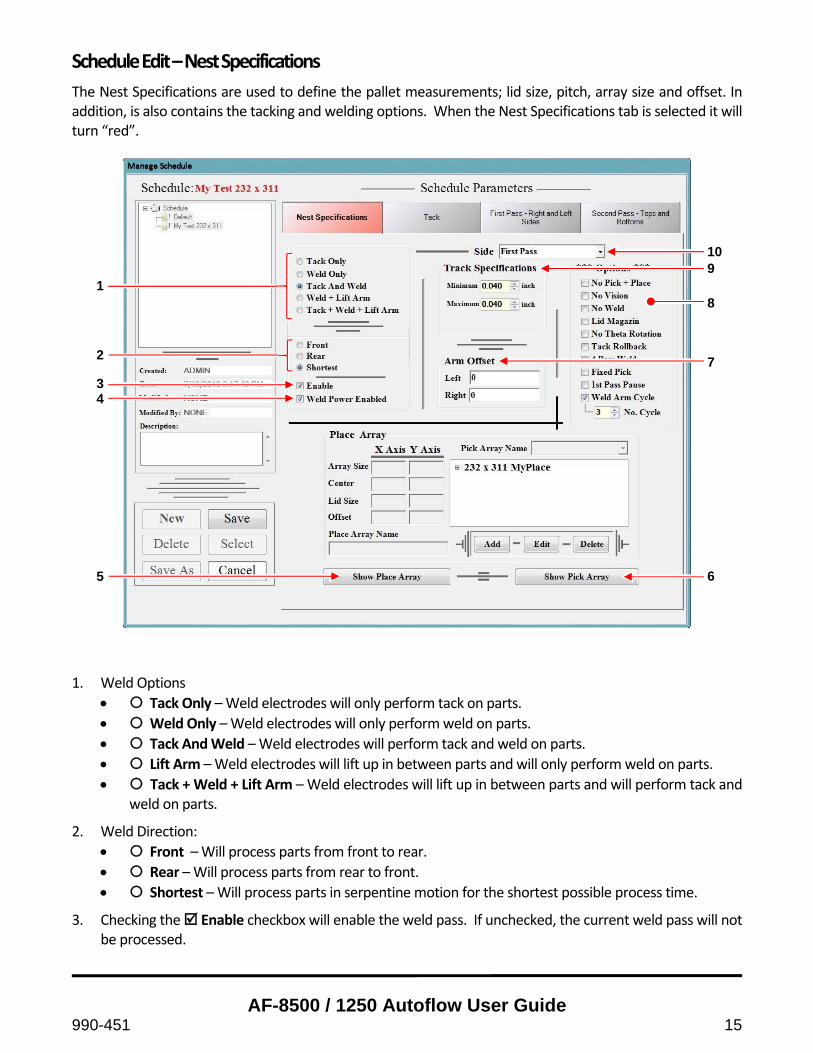
Schedule Edit – Nest Specifications
The Nest Specifications are used to define the pallet measurements; lid size, pitch, array size and offset. In addition, is also contains the tacking and welding options. When the Nest Specifications tab is selected it will turn “red”.
1. Weld Options
Tack Only – Weld electrodes will only perform tack on parts.
Weld Only – Weld electrodes will only perform weld on parts.
Tack And Weld – Weld electrodes will perform tack and weld on parts.
Lift Arm – Weld electrodes will lift up in between parts and will only perform weld on parts.
Tack + Weld + Lift Arm – Weld electrodes will lift up in between parts and will perform tack and weld on parts.
2. Weld Direction:
Front – Will process parts from front to rear.
Rear – Will process parts from rear to front.
Shortest – Will process parts in serpentine motion for the shortest possible process time.
3. Checking the Enable checkbox will enable the weld pass. If unchecked, the current weld pass will not be processed.
1
2
3 4
5
10 9
8
7 6

AF-8500 / 1250 Autoflow User Guide
16 990-451
4. When Weld Power Enabled is checked, the lid will be welded to the base during runtime. Uncheck this box when you are testing the pick and place consistency and repeatability to avoid welding.
5. When Show Place Array is selected, the Place Array data fields will display. The Place Array stores numbers being used by the system to determine the location of the parts on the pallet. These numbers are usually obtained from a mechanical drawing of the pallet.
Array Size determines the number of parts in the X and Y axis.
Center determines the pitch or the distance between the center of a part to the center of the next part in the pallet.
Lid Size determines the size of the lid in inches.
Offset is the distance from the table center to the center of the place array.
Pick Array Name associates a pick array with the current placed array. The current place array name is displayed in the box below the Pick Array Name. Selecting the “plus” icon next to it will display the pick array name.
Select Add to add a place array and Delete to delete a place array.
Select Edit to edit the numbers on the place array. Selecting Edit will change the options to Save and Cancel.
6. When Pick Array is selected, the Pick Array data fields will display. The Pick Array stores numbers being
used by the system to determine the location of the lids on the pallet. These numbers are usually obtained from a mechanical drawing of the pallet.
Array Size determines the number of lids in the X and Y axis.
Center determines the pitch or the distance between the center of a lid to the center of the next lid in the pallet.
Offset is the distance from the table center to the center of the pick array. The box next to it displays the list of the pick array that can be selected from the Place Array setting.
Select Add to add a pick array and Delete to delete a pick array.
Select Edit to edit the numbers on the pick array. Selecting Edit will change the options into Save and Cancel.

AF-8500 / 1250 Autoflow User Guide
990-451 17
7. Arm Offset enables the user to adjust the arm in both the left and right directions. By default, this option should be 0. Use negative and positive numbers for the left arm to offset left and right respectively. The polarity of the right arm is reversed; use negative and positive numbers for the right arm to offset right and left respectively.
8. The Options menu has several options that can be enabled or disabled. Option enabled when selected.
No Pick + Place will disable the pick and place button on the Main Control Screen.
No Vision will disable the vision button in the Main Control Screen.
No Weld will disable the weld button in the Main Control Screen.
Lid Magazine will enable the add‐on lid elevator system.
No Theta Rotation will disable the rotation correction being done by the pick stem.
Tack Rollback will enable the system to move the table slightly after tacking to prevent electrode from sticking onto the part. This is useful especially for smaller part geometries.
4 Pass Weld will enable the 4 pass weld mode where it starts from the center and weld the top half of the part before moving back to the center and weld the bottom half.
Fixed Pick will enable the add‐on lid centering device.
Weld Arm Cycle will only cycle the weld arm down and up before the welding process at the indicated number of cycles two (2) hours from the most recent weld arm operation. This two (2) hour interval can be changed in the AFLOW.ini file. Cycling the pneumatic cylinders (which the electrodes are mounted on), will break static freeze between the O‐rings and the cylinder walls after the cylinder is not being used for a few hours.
9. Side determines which pass is being edited. The Options are First Pass and Second Pass. First pass edits the process when the table is at 0 degrees. Second pass edits the process when the table is at 90 degrees.
10. Track Specifications determines the minimum and maximum electrode track, which is the distance from the edge to the surface of the electrode being used to where the parts are processed.
AF-8500 / 1250 Autoflow User Guide
18 990-451
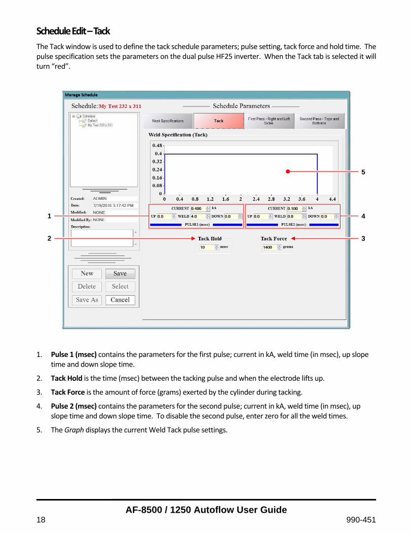
Schedule Edit – Tack
The Tack window is used to define the tack schedule parameters; pulse setting, tack force and hold time. The pulse specification sets the parameters on the dual pulse HF25 inverter. When the Tack tab is selected it will turn “red”.
1. Pulse 1 (msec) contains the parameters for the first pulse; current in kA, weld time (in msec), up slope
time and down slope time.
2. Tack Hold is the time (msec) between the tacking pulse and when the electrode lifts up.
3. Tack Force is the amount of force (grams) exerted by the cylinder during tacking.
4. Pulse 2 (msec) contains the parameters for the second pulse; current in kA, weld time (in msec), up slope time and down slope time. To disable the second pulse, enter zero for all the weld times.
5. The Graph displays the current Weld Tack pulse settings.
1
2
5
4
3

AF-8500 / 1250 Autoflow User Guide
990-451 19
Schedule Edit – First Pass – Right and Left Sides
The First Pass window is used to define the first pass weld schedule parameters for the Right and Left sides; pulse setting, corner density, spot spacing, speed, force, rollback and over travel. The pulse specification sets the parameters on the dual pulse HF25 inverter. When the First Pass – Right and Left Sides tab is selected it will turn “red”.
1) Pulse 1 (msec) contains the parameters for the first pulse; current in kA, weld time (in msec), up slope
time and down slope time.
2) Corner Density (Y) allows the user to adjust the amount of pulse applied to the part during the portions of the weld near the corners. By entering a Start Multiplier value greater than 1, more pulse will be applied by way of decreasing the spot spacing by an amount equal to the inverse of the start multiplier. The length is specified in the Start Multiplier Length field. End multiplier works the same way except Start Multiplier starts at the beginning of the part while End Multiplier starts before the end of the part.
3) Spot Spacing (Y) is the distance in inches from center to center between each weld pulse. The initial weld pulse for each package starts from the corner plus the Over Travel for the quad mode or the center plus the overlap for the 4pass mode. Each subsequent weld pulse is spaced evenly based upon the spot spacing value. The AF‐1250/8500 uses precision encoders and high accuracy servo motors to deliver this weld spot spacing with high accuracy. While setting the spot spacing in conjunction with the weld speed, it is
1
2
10
9
3 4 5 6 7 8

AF-8500 / 1250 Autoflow User Guide
20 990-451
important to keep in mind the repetition rate of the HF25 power supply. It is possible to program the system so that the weld pulses are closer and faster than the HF25 can accommodate. In this situation, although the electrodes will travel at the requested speed and the power supply will be triggered to send a weld pulse, the requested energy will not be delivered to the weld site.
4) Over Travel (Y) parameter determines the distance of travel before and after the length or width of the part. This parameter accounts for the radiuses in the corners as it causes the welder to fire pulses as it rolls beyond the corner of the part.
5) Weld Speed (Y) is set in inches per second. It determines how fast the electrodes move over the surface of the lid package during welding. As noted above, it is important to keep in mind the repetition rate of the HF25 power supply.
6) Weld Percent (Y) defines how much of a side needs to be welded. For example, if Weld Percent is 90% for a 1” x 1” part, only 0.9” of the part will be welded and the remaining 0.1” will be unwelded.
7) Weld Force value is the force in grams that will be applied to the contact area between the electrodes and the part being welded. Typical force applied to the ceramic package is 1400 grams.
8) Rollback is a unique feature where the electrodes move in reverse direction of the welding. This motion is done right after the last pulse is being fired during welding. This feature keeps the parts (especially low mass) from sticking to the electrodes after the final weld pulse. The rollback is set as a percentage of the total distance along the edge of the part.
9) Pulse 2 (msec) contains the parameters for the first pulse; current in kA, weld time (in msec), up slope time and down slope time. To disable the second pulse, enter zero for all the weld times.
10) The Graph displays the current Weld Tack pulse settings.
AF-8500 / 1250 Autoflow User Guide
990-451 21
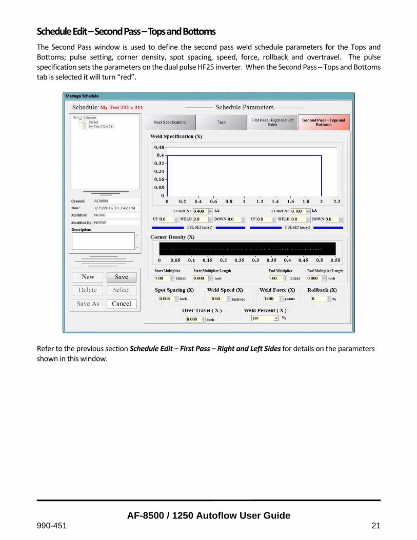
Schedule Edit – Second Pass – Tops and Bottoms
The Second Pass window is used to define the second pass weld schedule parameters for the Tops and Bottoms; pulse setting, corner density, spot spacing, speed, force, rollback and overtravel. The pulse specification sets the parameters on the dual pulse HF25 inverter. When the Second Pass – Tops and Bottoms tab is selected it will turn “red”.
Refer to the previous section Schedule Edit – First Pass – Right and Left Sides for details on the parameters shown in this window.

AF-8500 / 1250 Autoflow User Guide
22 990-451
Messages Tab
The Messages Tab display AF‐8500/1250 Messages and set some global settings.
1) Message box displays the status of the AF‐1250/8500 system.
2) Selecting the Auto, Manual or Step mode:
Auto mode runs the schedule from the first selected part to the last selected part without stopping.
Manual mode runs the schedule one part at a time, stopping after each part. Pressing the Start button continues the process.
Step mode runs the schedule one step at a time, stopping after each step. Pressing the Start button continues the step process.
3) Vacuum Chuck Enable is used to enable/disable the vacuum when testing the Pick Head Up/Down.
4) The Row and Column fields display the row and column number of the current part being processed. In addition, the adjacent rectangle displays a color to indicate the current process. The process colors are defined on the Parts Tab (see below).
1
2
4
4 3

AF-8500 / 1250 Autoflow User Guide
990-451 23
Parts Tab
The Parts tab displays the array of parts to be welded.
1. Legend displays the description of each color and its associated process. When viewing the Messages
Tab, these colors can be used to indicate the current process.
2. Display of part arrays of the currently selected schedule. Parts can be selected or deselected by clicking on the part. Selected parts are displayed as white while parts not selected are displayed as black.
3. Reset Pick Array will reset the pick stem motion so that it processes the lid from the beginning of the array. If this button is not pressed prior to process, the pick stem will continue processing from the last pick array location of the previous process.
1
2
3
AF-8500 / 1250 Autoflow User Guide
24 990-451
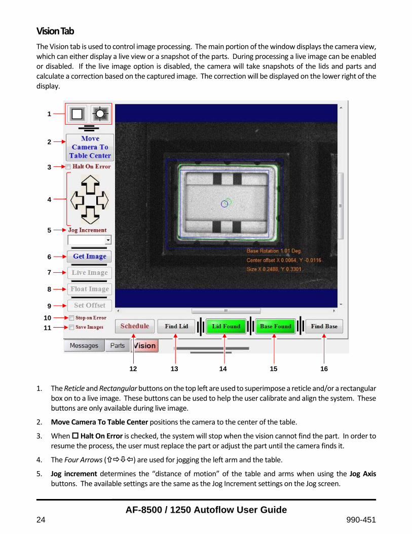
Vision Tab
The Vision tab is used to control image processing. The main portion of the window displays the camera view, which can either display a live view or a snapshot of the parts. During processing a live image can be enabled or disabled. If the live image option is disabled, the camera will take snapshots of the lids and parts and calculate a correction based on the captured image. The correction will be displayed on the lower right of the display.
1. The Reticle and Rectangular buttons on the top left are used to superimpose a reticle and/or a rectangular
box on to a live image. These buttons can be used to help the user calibrate and align the system. These buttons are only available during live image.
2. Move Camera To Table Center positions the camera to the center of the table.
3. When Halt On Error is checked, the system will stop when the vision cannot find the part. In order to resume the process, the user must replace the part or adjust the part until the camera finds it.
4. The Four Arrows () are used for jogging the left arm and the table.
5. Jog increment determines the “distance of motion” of the table and arms when using the Jog Axis buttons. The available settings are the same as the Jog Increment settings on the Jog screen.
1
2
3
4
5
6
7
8
9
10
11
12 13 14 15 16

AF-8500 / 1250 Autoflow User Guide
990-451 25
6. Get Image captures a snapshot at the current position.
7. Live Image sets the camera to view a live image.
8. Float Image opens a new window with a live image of the camera.
9. Set Offset sets the table center reference of the camera.
10. When the Stop on Error option is selected, the system will stop the pick/place welding process when it encounters an error such as a misaligned lid.
11. When the Save Images option is selected, the software will capture and archive the images of the found lid and base for each part when performing the pick/place welding process. All captured images will include graphical overlays to indicate how the vision system saw the orientation of the part and will provide the (x,y) location and angle of orientation data.
12. Schedule opens up two options whether to calibrate the vision or edit the vision schedule. Please refer to section Vision Schedule Calibrate or Vision Schedule Edit for more information.
13. Find Lid will drive the camera to browse through all of the lids available in the lid arrays. The camera will
capture a snapshot of each lid and calculate the error. Find Lid will have to be clicked again to browse to the next lid. Select any part in Parts Tab then select this button to start the motion.
14. Lid Found / Lid Error is an indicator that displays the status of the vision when browsing through a lid array. If the vision finds a lid, a Lid Found message with green background will be displayed. If the vision fails to find a lid, a Lid Error message with red background is displayed.
15. Base Found / Base Error is an indicator that displays the status of the vision when browsing through the part array. If the vision finds a part, a Base Found message with green background is displayed. If the vision fails to find a part, a Base Error message with red background is displayed.
16. Find Base will drive the camera to browse through the part(s) that are selected in the Parts tab. The camera will capture a snapshot of each part and calculate the error. Find Base will have to be selected again to browse to the next part unless only one part is selected from the part array. Select any part in Parts Tab then select this button to start the motion. The camera will only browse through the parts selected in the Parts Tab.

AF-8500 / 1250 Autoflow User Guide
26 990-451
Vision Schedule Calibrate
Before the camera can be used, the vision software must be calibrated. The calibration screen is displayed below. Vision Calibration can be accessed by selecting Schedule from the Vision Tab window, followed by Vision Schedule Calibrate. There are three steps required to calibrate the vision system and are separated by tabs (Step One, Step Two, Step Three)
Step One ‐ tab
The camera must be looking down on a lid or a part with a known size (as verified by calipers). Using a square lid is highly recommended to avoid X and Y confusion.
1. Enter the known X and Y dimensions of the part/lid in Calibrator Size fields. Make sure Inch is selected if measuring in inches, or mm if measuring in millimeters.
2. Select the Calibrator is not on center or aligned to Axis option.
3. Click Grab New Calibration Image to grab a screenshot.
4. Select the Step Two tab.
4 1
2 3
AF-8500 / 1250 Autoflow User Guide
990-451 27
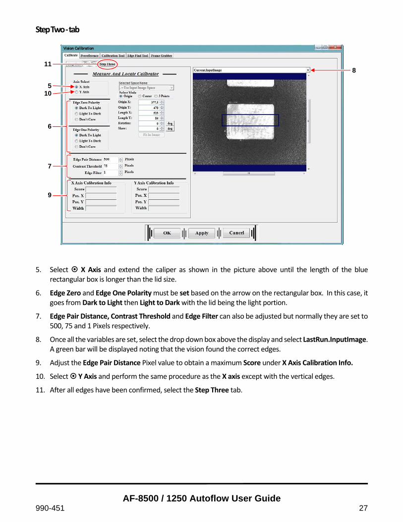
Step Two ‐ tab
5. Select X Axis and extend the caliper as shown in the picture above until the length of the blue
rectangular box is longer than the lid size.
6. Edge Zero and Edge One Polarity must be set based on the arrow on the rectangular box. In this case, it goes from Dark to Light then Light to Dark with the lid being the light portion.
7. Edge Pair Distance, Contrast Threshold and Edge Filter can also be adjusted but normally they are set to 500, 75 and 1 Pixels respectively.
8. Once all the variables are set, select the drop down box above the display and select LastRun.InputImage. A green bar will be displayed noting that the vision found the correct edges.
9. Adjust the Edge Pair Distance Pixel value to obtain a maximum Score under X Axis Calibration Info.
10. Select Y Axis and perform the same procedure as the X axis except with the vertical edges.
11. After all edges have been confirmed, select the Step Three tab.
11
5 10
6
7
9
8

AF-8500 / 1250 Autoflow User Guide
28 990-451
Step Three ‐ tab
12. Select Calibrate to calibrate the vision system.
13. Once calibration is complete, select OK to complete the calibration procedure.
12 13

AF-8500 / 1250 Autoflow User Guide
990-451 29
Vision Schedule Edit
Before entering the Vision Schedule Edit, start the system in Step mode (enabled on the Messages tab), while P&P and Vision are enabled from the Main Screen (both buttons should be yellow) so that the camera will stop directly above the lid. Lid Edge
1. Select the Edge Find tab to start fine tuning the vision system for lid detection.
2. Adjust the caliper so that the edge of the lid is on the blue line in the middle of each caliper. The parameters (size, length, etc.) of the calipers can be adjusted using the following parameters:
Number of Calipers is the amount of caliper segments being used to detect the edge.
Search Length is the length of the caliper being used for detecting the edge.
Projection Length is the width of the caliper.
Swap Search Direction will swap the arrow which determines the direction of searching. Change the direction in conjunction with Edge 0 Polarity in Caliper Settings tab.
Number to Ignore is the amount of caliper segments that will be ignored. This is useful when there is a defective edge on the part or lid.
3. Select the Lid Edge button (located on the lower left side of the screen).
4. Verify the Lid Locate Edges pull‐down option is selected under the Run Results section.
5. Select the Caliper Settings tab.
1 2 3
4
5
8

AF-8500 / 1250 Autoflow User Guide
30 990-451
6. Edge 0 Polarity should be set according to the Swap Search Direction setting on the Settings tab. If the
caliper searches from the inside of the lid to the outside of the lid such as in the picture above, the setting should be Light to Dark.
7. Contrast Threshold and Filter Half Size Pixels can also be adjusted to aid in the edge detection.
8. Select Run Vision on the Settings tab to check if the vision finds the lid. If the camera does not detect the lid, make proper adjustment to the calipers and the variables before running the test again.
9. Select LastRun.InputImage from the drop down box on top of the display to show the results of the caliper. Green indicates it found the edge while red indicates either it did not find the edge or it is one of the ignored calipers.
10. Repeat this process for the other three lid edges.
6
7
9

AF-8500 / 1250 Autoflow User Guide
990-451 31
Base Edge
The Base Edge settings have the same functionality as the Lid Edge settings. However, setting the base edge calipers is usually more complex than then lid edge calipers because the base contains many different reflective surfaces. Finding the wrong edge will not be good for the accuracy of the lid placement. Therefore, configuring the base edge setting usually takes more time. Before entering the Vision Schedule Edit, select a part from the array and make sure it is populated. Like the Lid Edge, start the system in Step mode while P&P and Vision are selected so that the camera will stop directly above a part.
1. Select the Edge Find tab to start fine tuning the vision system for lid detection.
2. Select the Base Edge button (located on the lower left side of the screen).
3. Verify the Base Locate Edges pull‐down option is selected under the Run Results section.
4. Adjust the calipers and variables the same way as noted above in the Lid Edge section.
5. Inner edges or outer edges of the part can be used. The example below uses the inner edge of the part.
Caution: If using the inner edge, the other three edges must also use the inner edges. This rule also applies for the outer edges. Failure to comply will result in lid misalignment
1
2
4
3

AF-8500 / 1250 Autoflow User Guide
32 990-451
6. Select LastRun.InputImage from the drop down box on top of the display to show the results of the
caliper. Green indicates it found the edge while red indicates either it did not find the edge or it is one of the ignored calipers.
7. Repeat the process for the other three edges.
6

AF-8500 / 1250 Autoflow User Guide
990-451 33
If either of the lid dimensions are larger than 1 inch, the vision system will perform a two‐corner vision mode inspection. The camera will look at the top left corner first, followed by the bottom right corner. In two‐corner vision mode, the Theta correction angle is calculated by comparing the seal ring dimensions to the lid dimensions. In most cases, the seal ring will be slightly larger than the lid size and its dimensions are proportional to the part. In the event that the seal ring is not proportional to the part, using the part dimensions can cause inaccuracies in the vision correction algorithm. To improve accuracy, the Seal Ring Size parameters have been added to the “Vision Schedule Editor”. The image below shows an example of a part where the seal ring dimensions are not proportional to the lid dimensions.
AF-8500 / 1250 Autoflow User Guide
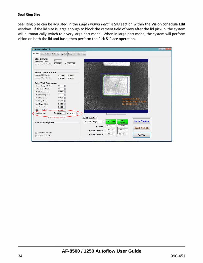
34 990-451
Seal Ring Size Seal Ring Size can be adjusted in the Edge Finding Parameters section within the Vision Schedule Edit window. If the lid size is large enough to block the camera field of view after the lid pickup, the system will automatically switch to a very large part mode. When in large part mode, the system will perform vision on both the lid and base, then perform the Pick & Place operation.

AF-8500 / 1250 Autoflow User Guide
990-451 35
Pull‐Down Menus
User Menu
The User menu is used to control who can access the AF system. The options include; Add User, Edit User, Change User and Delete User.
Add User – Allows Administrator to add a User. An Operator without Administrator privileges cannot add a user.
Enter displayed user name
Enter User ID and Password (twice)
Select access privileges for the user
Select OK to add new User
Edit User – Allows either a User or Administrator to change their password.
Type in a new Password (twice)
Select OK to register new password

AF-8500 / 1250 Autoflow User Guide
36 990-451
Change User – Allows the current User to change to another User.
Select a different User from the window.
Log‐in using the new User’s ID and Password
Delete User – Allows the Administrator to delete a User. Users without Administrator privileges cannot delete a User.
Select the User that you want to delete.

AF-8500 / 1250 Autoflow User Guide
990-451 37
System Settings Menu
The System Settings menu consists of global system settings and status. The options include; IO Status, Vacuum Set‐Point, Motion Limit Setting, Force Calibration and System Configuration. 1) IO Status Display
The IO screen displays the status of the motion controller, digital and analog inputs and all three axes. In addition the Digital outputs can also be triggered.
The IO screen is very useful for troubleshooting and calibrating the system.

AF-8500 / 1250 Autoflow User Guide
38 990-451
2) Vacuum Setpoint
The motion controller reads the vacuum level as an analog input. All vacuum setpoints for the vacuum system are set on this screen. The default Pick Vacuum Setpoint is 3.2. This value defines the minimum acceptable vacuum level. If the motion controller reads the vacuum level and its value is below 3.2, then the system will report no vacuum.
3) Motion Limit Setting
Get Limits is performed during system calibration. The main purpose of the Get Limits test is to determine the maximum travel distance for all axes. The values are stored in the settings file and displayed on the Motion Limit Setting screen. When Get Limits is selected, the system will perform a motions test that will calculate the travel limits. Select Save once the motion test is complete.
AF-8500 / 1250 Autoflow User Guide
990-451 39
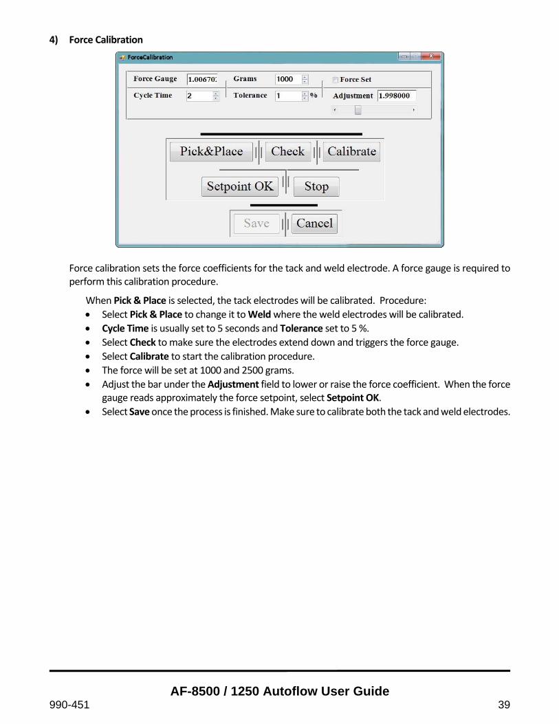
4) Force Calibration
Force calibration sets the force coefficients for the tack and weld electrode. A force gauge is required to perform this calibration procedure.
When Pick & Place is selected, the tack electrodes will be calibrated. Procedure:
Select Pick & Place to change it to Weld where the weld electrodes will be calibrated.
Cycle Time is usually set to 5 seconds and Tolerance set to 5 %.
Select Check to make sure the electrodes extend down and triggers the force gauge.
Select Calibrate to start the calibration procedure.
The force will be set at 1000 and 2500 grams.
Adjust the bar under the Adjustment field to lower or raise the force coefficient. When the force gauge reads approximately the force setpoint, select Setpoint OK.
Select Save once the process is finished. Make sure to calibrate both the tack and weld electrodes.

AF-8500 / 1250 Autoflow User Guide
40 990-451
5) System Configuration
The system configuration windows consists of:
Lid Feeder Type a) Magazine Feeder – Lids are being fed using a lid magazine. b) Fixed Feeder – Lids are being fed with a fixed mechanical fixture. c) No Feeder – Lid feeder is not available.
Part Feeder Type
a) Standard Auer Boat Loader – Parts are loaded on an Auer Boat magazine. b) No Part Loader – Part loader is not available.
System Options
a) Wide Nest b) Batch Rpt Enable c) Multi‐Lid Nest d) Has Lid Centering Device – Lid Centering Device is available to hold the lid where it will be picked
by the pick head. e) Has Smart Nest – Smart Nest loads Auer Boats and has vacuum chuck that holds down parts before
they are being processed. f) Rotary Table – Adds a table rotate option for seamsealing both the horizontal and vertical sides of
the part. g) Weld Monitor – Add a weld monitor option. This option includes interrupting the motion when
the weld monitor detects sparks during the seamsealing process. h) Vacuum Chuck Enable – Vacuum chuck holds down parts seated in the nest to ensure parts do
not move during motion.

AF-8500 / 1250 Autoflow User Guide
990-451 41
Help Menu
The Help menu gives information About the current version of the software.
Troubleshooting – Commonly Encountered Difficulties
The following is a list of common situations and solutions that will solve most problems encountered by operators in the course of normal Autoflow operation. If other problems occur that require further assistance, please call your Amada Miyachi America service technician.
PROBLEM SOLUTION
No buttons can be selected during software start‐up
Home the System
System will not perform motion. Pick head and weld electrodes extend down.
Check process gas supply connection. Leak check hoses and connections. Minimum supply pressure is 55‐60psi.
System does not tack or weld Check the HF25 Power Supply. Make sure the switch is
at the Weld position.
No lid detected by the vacuum switch Make sure lids are loaded and vacuum is on
System loses power by power outage or emergency stop Restore the power (E‐Stop button must be in reset position) and restart the application software.
Error message: Lid on pickstem Remove lid from the pick stem or select start to use the
lid on the pick stem for the next part.

AF-8500 / 1250 Autoflow User Guide
42 990-451
Safety Factors
Because the Autoflow designers have done everything to make the Autoflow system as safe as possible, Autoflow has a remarkable history of safe operation. The following suggestions are offered to remind operators of common procedures that promote safety for the operator and for the Autoflow system.
A. Operator Safety
(1) Always keep hands and clothing securely away from the part nest, the rotary table and the welding and tacking arms when operating the system.
(2) Turn OFF the power at the main control panel when not in use for long periods of time or during maintenance.
(3) Log off when leaving the system unattended.
B. Equipment Safety
(1) Replace worn electrical cords and hoses at the first appearance of wear.
(2) Regularly inspect the Autoflow electrodes to maintain quality performance.
(3) Regularly back‐up the Autoflow database files.
Autoflow Operating Instructions
(1) At the logon screen, enter your username and password and click OK.
(2) At the main screen, click on the Home button to place all elements in their starting positions. This may take about 30 seconds.
(3) Click on the Schedule button and select Change Schedule to pick from a list of schedules in the drop down box. Select one and click OK.
(4) Place the part nest on the welding table. Be sure that the nest is level and securely in place.
(5) View the part array display to confirm that the display matches the actual part layout.
(6) Load the lids so that they are available for the Pick and Place head.
(7) Click the Check button to confirm that alignment and set up parameters are correct. (This step only needs to be done once before each new schedule runs.)
(8) Select the appropriate choices from the welder controls: P&P, Vision and Weld. When selected, each control button will have a yellow background. Clicking on the selection again turns off the function (red background).
(9) Click Start to run the schedule from beginning to end.
(10) Remove the parts when the schedule is complete.
(11) To run the same schedule again, reload the lids and parts on the nest and click Start. To switch to a new schedule, repeat steps 3 through 9.

AF-8500 / 1250 Autoflow User Guide
990-451 43
Inputs and Outputs
I/O for AF‐8500
The AF‐8500 input and output assignments are as follows:
Input Type High Low 1 N/A N/A N/A
2 Weld Arms Sensor Weld Arms Up Weld Arms Down
3 N/A N/A N/A
4 N/A N/A N/A
5 Table Not at 0° Not at 0° At 0°
6 Pick Head Sensor Pick Head Up Pick Head Down
7 Table Not at 90° Not at 90° At 90°
8 N/A N/A N/A
Analog Input Pin Type
1 3 Pick Up Vacuum
2 4 Transducer Output
Output Type High Low Solenoid 1 Weld Arms Arms Down Arms Up 1 & 8
2 Pick Head Head Down Head Up 2 & 3
3 Fill Valve On Off 4
4 Exhaust Valve On Off 5
5 Pick Vacuum On Off 6
6 Theta Step Not Step Step N/A
7 Theta Direction Clockwise Counterclockwise N/A
8 Table Rotate Valve Rotate to 90° Rotate to 0° 7

AF-8500 / 1250 Autoflow User Guide
44 990-451
I/O for AF‐1250
The AF‐1250 inputs assignment are as follows:
Input Type High Low 1 N/A N/A N/A
2 Weld Arms Not Down Weld Arms Up Weld Arms Down
3 Lid Lifter @ Load N/A N/A
4 N/A N/A N/A
5 Rotary Table not @ 0° Not at 0° At 0°
6 Pick Head Not Down Pick Head Up Pick Head Down
7 Rotary Table not @ 90° Not at 90° At 90°
8 Lid Proximity Sensor N/A N/A
17 Boat On Table Not Not on Table On Table
18 Weld Monitor Error No Error Error
19 N/A N/A N/A
20 N/A N/A N/A
21 N/A N/A N/A
22 N/A N/A N/A
23 N/A N/A N/A
24 Boat Not Down Not Down Down
25 N/A N/A N/A
26 N/A N/A N/A
27 N/A N/A N/A
28 From PLC Loader Ready N/A N/A
29 From PLC Unload Done N/A N/A
30 N/A N/A N/A
31 Lid Xfer Extended N/A N/A
32 Lid Xfr Retracted N/A N/A
Analog Input Pin Type
1 3 Pick Up Vacuum
2 4 Transducer Output
3 5 Vacuum Chuck
5 7 Precisor Vacuum
6 8 Transfer Vacuum
AF-8500 / 1250 Autoflow User Guide
990-451 45
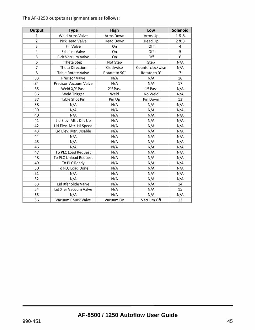
The AF‐1250 outputs assignment are as follows:
Output Type High Low Solenoid 1 Weld Arms Valve Arms Down Arms Up 1 & 8
2 Pick Head Valve Head Down Head Up 2 & 3
3 Fill Valve On Off 4
4 Exhaust Valve On Off 5
5 Pick Vacuum Valve On Off 6
6 Theta Step Not Step Step N/A
7 Theta Direction Clockwise Counterclockwise N/A
8 Table Rotate Valve Rotate to 90° Rotate to 0° 7
33 Precisor Valve N/A N/A 16
34 Precisor Vacuum Valve N/A N/A 17
35 Weld X/Y Pass 2nd Pass 1st Pass N/A
36 Weld Trigger Weld No Weld N/A
37 Table Shot Pin Pin Up Pin Down 13
38 N/A N/A N/A N/A
39 N/A N/A N/A N/A
40 N/A N/A N/A N/A
41 Lid Elev. Mtr. Dir. Up N/A N/A N/A
42 Lid Elev. Mtr. Hi‐Speed N/A N/A N/A
43 Lid Elev. Mtr. Disable N/A N/A N/A
44 N/A N/A N/A N/A
45 N/A N/A N/A N/A
46 N/A N/A N/A N/A
47 To PLC Load Request N/A N/A N/A
48 To PLC Unload Request N/A N/A N/A
49 To PLC Ready N/A N/A N/A
50 To PLC Load Done N/A N/A N/A
51 N/A N/A N/A N/A
52 N/A N/A N/A N/A
53 Lid Xfer Slide Valve N/A N/A 14
54 Lid Xfer Vacuum Valve N/A N/A 15
55 N/A N/A N/A N/A
56 Vacuum Chuck Valve Vacuum On Vacuum Off 12

AF-8500 / 1250 Autoflow User Guide
46 990-451
Appendix ‐‐ Schedule Development
Principles of Seam Sealing
Resistance Welding
Contact Resistance Generated By Placing An Electrode Into Contact With Part Lid
Electrode Angle
Shallower Angle
Decreased Contact Resistance
Distribute Heat More Evenly In Lid
Increased Stitch Width
More Energy Required To Maintain Metals At Molten Level
Electrode Force
Force Increased
Range Of Temperatures At Which The Metals Remains Molten Becomes Wider
Temperature Less Critical
Contact Resistance Is Decreased
Less Energy Available At The Weld
More Intimate Contact Between Lid, Seal Ring, And Electrode Surface
Decreased Heat In Lid
Increased Heat In Package
Increased Stitch Width
Appearance Of Stitches Appear Smoother
Speed
Speed Increased
Distance Between Stitch Stays The Same
HF Spot Spacing Remains Constant Within Speed Range
Increased Stitch Width, But Only If The Energy Delivered By Each Pulse Is Enough To Melt The Metals
Power
Power Increased
Increases Radius Of Weld Nugget
Increases Weld Penetration Through Lid And Seal Ring
Schedule development requires a general knowledge of seam sealing prior to schedule development with the high frequency inverter system
Tools
Microscope
Log sheet
Parts and nesting / tooling
Procedure
Tack lid with minimal setting
‘Standard Weld Pass’
Identify physical dimensions of part and enter into schedule
Spot spacing 0.010 inches
Halving the spot spacing doubles the power delivered to the package