HERMETIC COATING OF OPTICAL FIBERS · 00 RADC-TR-87-200 00 Fma TeekcalI Report 0) November 1W87 00...
44
00 RADC-TR-87-200 00 Fma TeekcalI Report November 1W87 0) 00 "'m I HERMETIC COATING OF OPTICAL FIBERS Spectran Corporation • S. Raychaudhur, Phfip a. AnadRyS M ROME AIR DEVELOPMENT CENTER Air Force Systems Command Griffiss Air Force Base, NY 13441-5700 88 1 20
Transcript of HERMETIC COATING OF OPTICAL FIBERS · 00 RADC-TR-87-200 00 Fma TeekcalI Report 0) November 1W87 00...

00 RADC-TR-87-20000 Fma TeekcalI Report
November 1W870)00
"'m
I
HERMETIC COATING OF OPTICAL FIBERS
Spectran Corporation •
S. Raychaudhur, Phfip a. AnadRyS M
ROME AIR DEVELOPMENT CENTERAir Force Systems Command
Griffiss Air Force Base, NY 13441-5700
88 1 20

t1 u vvr W LIT L WrM. T .WIN WU K .A.R Sw i WI
-' This report has been reviewed by the RADC Public Affairs Office (PA) andis releasable to the National Technical Information Service (NTIS). At NTISit will be releasable to the general public, including foreign nations.
"RADC-TR-8/-200 has been reviewed and is approved for publication.
APPROVED: dAJrL ~ ?
OSAMA H. EL-BAYOUMIProject Engineer
APPROVED: HAROLD ROTHDirector of Solid State Sciences
'5.
FOR THE COMMANDER:5-,
JOHN A RITZ*. Directorate of Plans & Programs
'V..
If your address has changed or if you wish to be removed from the RADCmailing list, or if the addressee is no longer employed by your organization,please notify RADC (ESM) Hanscom AFB MA 01731-5000. This will assist us in"maintaining a current mailing list.
Do not return copies of this report unless contractual obligations ornotices on a specific document require that it be returned.
"6i

UNCLASSIFIEDSECURITY CLASSIFICATION OF "I-.r5 PAGE
PForm AoprovedREPORT DOCUMENTATION PAGE _7 8 No. 0704-0188
!a. REPORT SECURITY CLASSIFICATION lb. RESTRICTIVE MARKINGS
LNýCLASSIFIED N/A2a. SECURITY CLASSIFICATION AUTHORITY 3. DISTRIBUTION /AVAILABILITY OF REPORT
N/A Approved for public release; distribution2b. OECLASSIFiCATION/DOWNGRADING SCHEDULE unlimited.N/A
4. PERFORMING ORGANIZATION REPORT NUMBER(S) S. MONITORING ORGANIZATION REPORT NUMBER(S)
N/A RADC-TR-87-200
6a. NAME OF PERFORMING ORGANIZATION 6b. OFFICE SYMBOL 7a. NAME OF MONITORING ORGANIZATIONSpectran Corporation (If applicable) Rome Air Development Center (ESM)
6c. ADDRESS (City, Stare, and ZIP Code) 7b. ADORESS (City, State. and ZIP Code)D0 Hall RoadStrubridge MA 01566 Hanscom AFB MA 01731-5000
8a. NAME OF FUNDING, SPONSORING lb. OFFICE SYMBOL 9 PROCUREMENT INSTRUMENT IDENTIFICATION NUMBERORGANIZATION (If applicable)
Rome Air Development Center ESM F30bO2-84-C-0199
8c. ADDRESS (City, State, and ZIP Code) 10. SOURCE OF FUNDING NUMBERS
Hanscom AFB MA 01731-5000 PROGRAM PROJECT TASK WORK UNITELEMENT NO. NO. NO IACCESSION NO.
b1102F 00.1 RA 17
11. TITLE (Include Security Claimficatton)
HERMETIC COATING OF OPTICAL FIBERS
"12. PERSONAL AUTHOR(S)S. Raychaudhuri, Philip S. Levin, Ray Sierra
13a. TYPE OF REPORT 73b TIME COVERED 114. DATE OF REPORT (Year, Month, Day) 15. PAGE COUNTFinal FROM Oct 84 TO Jun 86 November 1987 48
16. SUPPLEMENTARY NOTATION
N/A
17 COSATI CODES 18. SUBJECT TERMS ((Jntinue on reverse if necessary and identify by block number)FIELD GROUP SUB-GROI Fiber Optics, Protective Coating, Hermetic Sealing,
11 02 ' High Strength Fiber0 ."11 03
19. ABSTRACT (Continue on reverse ,f necessry and identify by block number)Hermetically coated graded index silica fibers were to exhibit proof test levels greater
than 200 Kpsi over one kilometer length Fiber was to exhibit a stress corrosion factorN greater than 100. The dielectric coating materials were to include, but not limited todiamond - like carbon and bororr nitride. Techniques using hollow cathode discharge coater
* produced coated fiber with N value less than 26. Severe arcing problems were faced withthis technique resulting in large cracks on the coater anodes. RF plasma coater was builtand operated to deposit amorphous, hydrogenated carbon (a - C:H) films both on bulk andfiber samples. Fibers were drawn under a number of conditions to determine the role, such
'I factors as vacuum chamber alignment, tension, plasma conditions play in the strength of the
. fiber. A stress corrosion susceptibility factor N - 26 was obtained. In only preliminaryexperiments with the deposition of !silicon nitride coating on the fiber, N values up to 70
were achieved. .__s; -
- 20 DISTRIBUTION / AVAILABILITY OF ABSTRACT 21 ABSTRACT SECURITY CLASSIFICATIONC 'UNCLASSIFIEDIUNLIMITEO r3 SAME AS RPT ] OTIC USERS UNCLASSIFIED
22a. NAME OF RESPONSIBLE INDIVIDUAL 22bTELEPH$NEI cludeAreaCode)122 OFFCE SOLOsama H. El-Bayoumi (617) 7-363 ADC( ESM)
00 Form 1473, JUN 86 Prev,ouseditionsae obsolete. SECURITY CLASSIFICATION OF THIS PAGE
UNCLASSIFIED
I
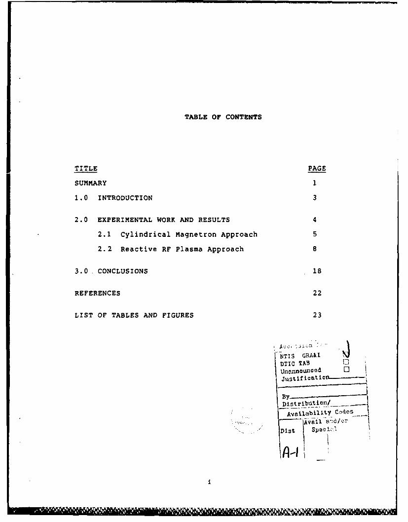
TABLE OF CONTENTS
TITLE PAGE
SUMMARY 1
1.0 INTRODUCTION 3
2.0 EXPERIMENTAL WORK AND RESULTS 4
2.1 Cylindrical Magnetron Approach 5
2.2 Reactive RF Plasma Approach 8
3.0. CONCLUSIONS 18
REFERENCES 22
LIST OF TABLES AND FIGURES 23
VTIAS GRA&I
DTIC TAB t
By___________
Avallabil~tY COdcs
-an~id/Qr
Dist 53)ecl'%
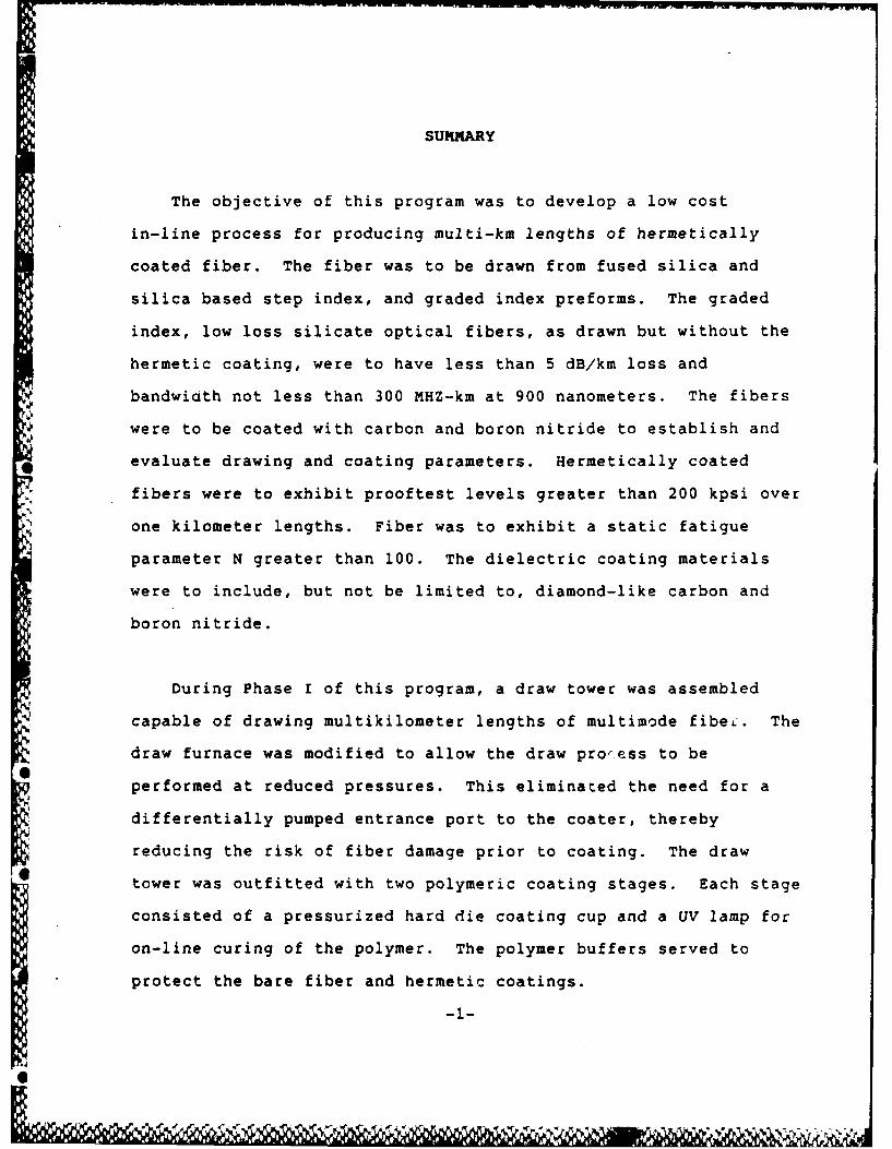
SUMMARY
The objective of this program was to develop a low cost
in-line process for producing multi-km lengths of hermetically
coated fiber. The fiber was to be drawn from fused silica and
silica based step index, and graded index preforms. The graded
index, low loss silicate optical fibers, as drawn but without the
hermetic coating, were to have less than 5 dB/km loss and
bandwiath not less than 300 MHZ-km at 900 nanometers. The fibers
were to be coated with carbon and boron nitride to establish and
evaluate drawing and coating parameters. Hermetically coated
fibers were to exhibit prooftest levels greater than 200 kpsi over
one kilometer lengths. Fiber was to exhibit a static fatigue
parameter N greater than 100. The dielectric coating materials
were to include, but not be limited to, diamond-like carbon and
boron nitride.
During Phase I of this program, a draw tower was assembled
capable of drawing multikilometer lengths of multimode fibeL. The
draw furnace was modified to allow the draw pro'ess to be
performed at reduced pressures. This eliminated the need for a
differentially pumped entrance port to the coater, thereby
reducing the risk of fiber damage prior to coating. The draw
tower was outfitted with two polymeric coating stages. Each stage
consisted of a pressurized hard die coating cup and a UV lamp for
on-line curing of the polymer. The polymer buffers served to
protect the bare fiber and hermetic coatings.
--1--

During Phase II, the initial effort was directed towards
building a one meter hollow cathode discharge coater for coating
the fiber. The coater section was isolated by means of
differentially pumped stages from both the low pressure inert
furnace invironment and from atmospheric contamination. The
coater was operated and fiber drawn from silica rods was coated.
Dynamic fatigue tests were performed with a gauge length of 11.5cm
and a stress corrosion coefficient of N-26 was demonstrated.
However, severe arcing problems were faced with this coater
arrangement - resulting in large cracks on the coater anodes.
A decision was made at this stage of the program to implement
an RF excited collisionally controlled glow discharge coater.
This coater was operated to deposit amorphous hydrogenated carbon
(a-C:H) films on both bulk and fiber samples. An optical
multichannel analyzer was used to monitor the glow discharge in
real time and optical emissions corresponding to efficient
deposition were identified. Bulk NaCl, sapphire and glass samples
coated with - 1 micron thick films were tested analytically. With
the information gathered through bulk deposition experiments,
efforts were directed to coat fibers with a-C:H films under
dynamic conditions. Fibers were drawn under a number of
conditions to determine the role such factors as vacuum chamber
alignment, tension, plasma conditions play in the strength of the
fiber. Modifications were implemented to allow better alignment
of the exit ports.
-2-

Fibers coated with a-C:H were evaluated by dynamic fatigue
testing. A stress corrosion susceptibility factor N-26 was
obtained. To improve on the N value, experiments were conducted
to coat fibers with materials like a-Si:H, a-SiC:H, Si 3 N4 , TiC and
BN. In preliminary experiments with the deposition of silicon
nitride coating on the fiber, N values up to 70 were achieved,
clearly verifying the capability of the RF plasma approach to
produce reasonable hermeticity while avoiding the problem
experienced with hollow cathode.
1.0 INTRODUCTION:
The surface of a freshly drawn glass fiber while
seemingly smooth has many imperfections which when under
stress, can grow and ultimately result in failure of the
fiber. Moisture can greatly increase the growth rate of such
flaws by chemical attack. Although typical communications
fibers are coated with some type of polymer, such polymers
provide little protection against moisture attack and the
mean failure stress of the fiber decreases with time at
essentially the same rate as an uncoated fiber. A thin
hermetic coating would protect the surface of the fiber
against moisture diffusion and would therefore preserve the
initial strength of the fiber. Many such coatings have been
investigated at SpecTran[5] and other facilities[I'2'3'4]
Ideally, a hermetic coating would be non-conducting and would
t.

have no effect on the optical properties of the fiber. The
coating would be applied during the draw phase of fiber
manufacture and should be compatible with all other normally
performed manufacturing steps (cabling, splicing, etc.).
The initial thrust of this program was to extend the
development of a previously reported approach[ 6 ' 7 1 for
applying diamond-like carbon hermetic coatings on optical
fibers. The technique involved the generation of a reactive
glow discharge using a cylindrical-hollow magnetron coupled
with a hollow cathode configuration. A mixture of methane
and argon was introduced into the coater and flowed
constantly during magnetron operation. This approach was
not, however, successful due to severe arcing.
As a result, an RF excited reactive plasma deposition
was adopted and more than ninety percent of the data
generated during Phase II were obtained using this system.
The remainder of this report describes in detail the work
performed under this contract.
2.0 EXPERIMENTAL WORK AND RESULTS:
The thrust of this program was to combine the fiber draw
technology with a viable hermetic coating process. Earlier
work had identified the transition length from the exit of
the draw furnace to the entrance of the hermetic coating
-4-
%
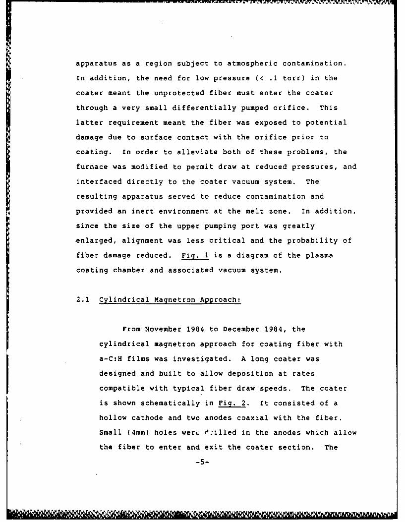
apparatus as a region subject to atmospheric contamination.
In addition, the need for low pressure (< .1 torr) in the
coater meant the unprotected fiber must enter the coater
through a very small differentially pumped orifice. This
latter requirement meant the fiber was exposed to potential
damage due to surface contact with the orifice prior to
coating. In order to alleviate both of these problems, the
furnace was modified to permit draw at reduced pressures, and
interfaced directly to the coater vacuum system. The
resulting apparatus served to reduce contamination and
provided an inert environment at the melt zone. In addition,
since the size of the upper pumping port was greatly
enlarged, alignment was less critical and the probability of
fiber damage reduced. F is a diagram of the plasma
coating chamber and associated vacuum system.
2.1 Cylindrical Magnetron Approach:
From November 1984 to December 1984, the
"cylindrical magnetron approach for coating fiber with
a-C:H films was investigated. A long coater was
designed and built to allow deposition at rates
compatible with typical fiber draw speeds. The coater
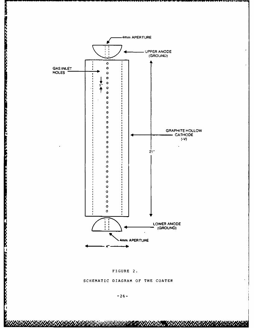
is shown schematically in Fig. 2. It consisted of a
hollow cathode and two anodes coaxial with the fiber.
Small (4mm) holes wer v4 :illed in the anodes which allow
the fiber to enter and exit the coater section. The
-5-

total coater was 1 meter long with an inside diameter of
4.4 cm. The cathode section was constructed of high
purity graphite and biased by means of Hippotronics high
voltage D.C. power supply. An axial magnetic field
between 80 and 300 gauss was applied with the intent of
establishing magnetron oscillations.
The system as implemented was found to be subject
to severe arcing near the anodes. Static experiments
conducted using view ports confirmed the difficulty in
sustaining a glow type discharge with the existing
coater design. Although arcing prevented the coater
from operating as intended, coatings were produced using
constantly flowing mixtures of methane and argon. Both
flow rates and compositions were varied. Silica rods
drawn into fiber and coated by means of the discharge
apparatus exhibited black sooty deposits. Fig. 3 shows
the results of a compositional analysis performed on a
typical coating using S.E.M/EDAX. As can be seen, the
film consisted mainly of carbon. Hydrogen, a
constituent commonly found in these films, was not
detectable by S.E.M., but could not be ruled out. The
resistivity of the coating was estimated from resistance
measurements and found to be 10 9-cm. This low
resistivity as opposed to the more insulating behavior
from DLC implied the film was essentially impure
graphite.

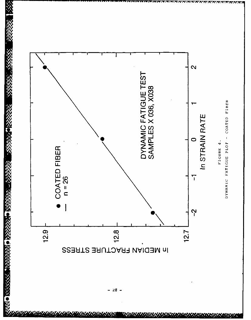
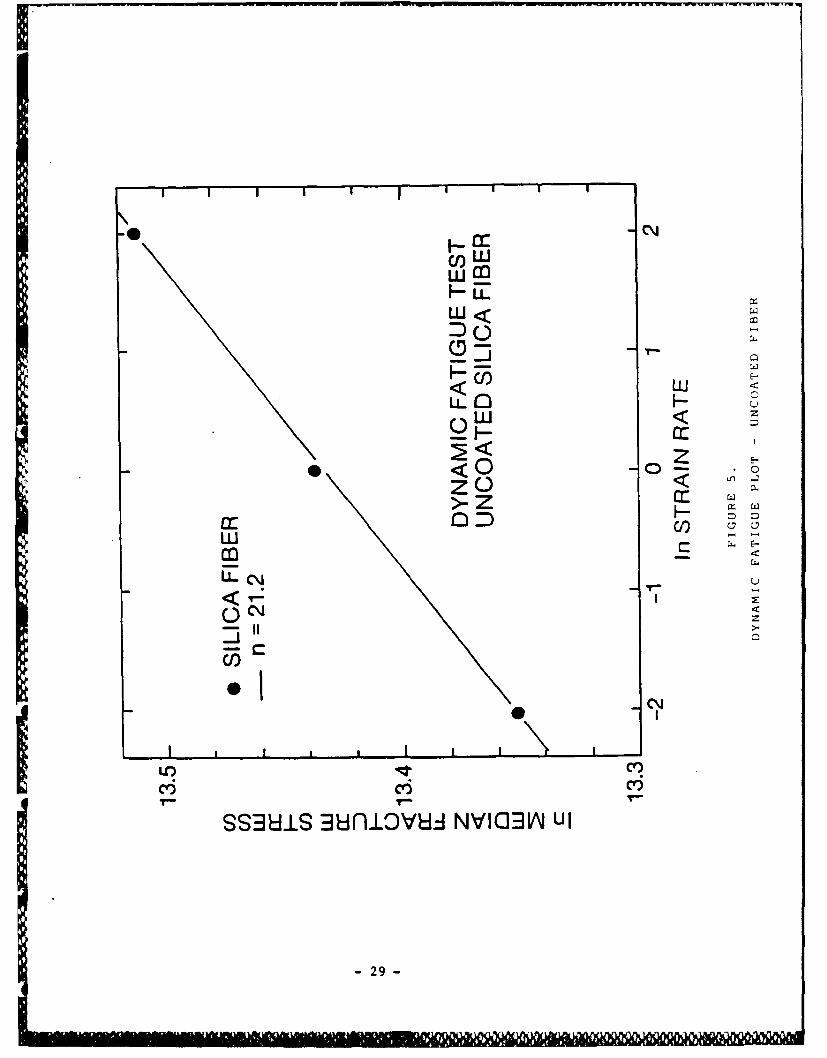
The coated fiber was tested using a dynamic fatigue
tester (Instron) to determine static fatigue
characteristics and hence evaluate coating hermeticity.
Using a gauge length of 11.5cm, Weibull plots were
generated at three strain rates covering two orders of
magnitude. Stress corrosion co-efficients (N) were then
calculated from the slope of a log-log plot of median
181failure stress vs loading rate]. As can be seen from
Fig. 4, the data yielded a straight line. An N value of
O 26 was computed. This was in reasonable agreement with
(6]earlier work where N-30 was reported. For
comparison, Fig. 5 shows similar data for control silica
fiber yielding a stress corrosion coefficient, N-21.2
indicating only slight improvement for the carbon coated
fiber.
The hollow cathode design was carefully reviewed by
both in-house personnel and discussed with Chatham
Cooke, a consultant from MIT. It was concluded that
large aspect ratio (length of cathode divided by inside
diameters) led to a very unstable discharge. The reason
for this instability was the large voltage required to
initiate a very low pressure (< 0.1 Torr) discharge. It
is often the case that at these large values of E/N
(electric field divided by gas number density),
secondary emission by ion bombardment of the electrodes
-7-
11 9
becomes the dominant source of electrons. Localized hot
spots can develop and arcing and sputtering commonly
occur. As a result, the coatings deposited using the
hollow cathode apparatus were found to be essentially
graphite and provided only very slight improvement in
static fatigue parameters.
2.2 Reactive RF Plasma Approach:
Collisionally controlled plasma glow discharges can
be used to deposit varieties of thin film coatings [9,101
including a-C:H. Such discharges are characterized by
operation in a pressure region where collisional
processes in the bulk gas control both the production
and loss of electrons and consequently determine all
discharge parameters. In such discharges, the role of
the electrodes is minimized. owing to the efficiency
with which collisional processes can distribute energy,
the mean kinetic energies of both the neutral and ionic
species tend to reach a thermal equilibrium. This is in
marked contrast with the low pressure (< 100 mTorr)
electrode controlled glow discharge commonly used in
hrrnmagnetron deposition work. Thus, the problem of
deposition from a collisionally controlled glow
discharge reduces to the creation, by means of gas
parameters (pressure, composition, etc.), of a chemical
environment that supports the deposition of a-C:H.
L
JI
<

One convenient way of generating a collisionally
controlled plasma glow discharge is by means of a low
power RF source. Most gases in the pressure range from
0.1 Torr to 10 Torr are readily ionized by alternating
fields in the 1-30 MHZ frequency range. A number of
features of RF excitation make it an ideal candidate for
use here. First, since the power supply can be
inductively coupled to the coater, the need for
electrodes (and consequently the feed-throughs, etc.
* required for these) disappears and vacuum integrity can
be improved. The length of the coating region can be
made arbitrary since any number of coupling coils can be
Sutilized. Finally, the system affords a means of
varying conditions easily.
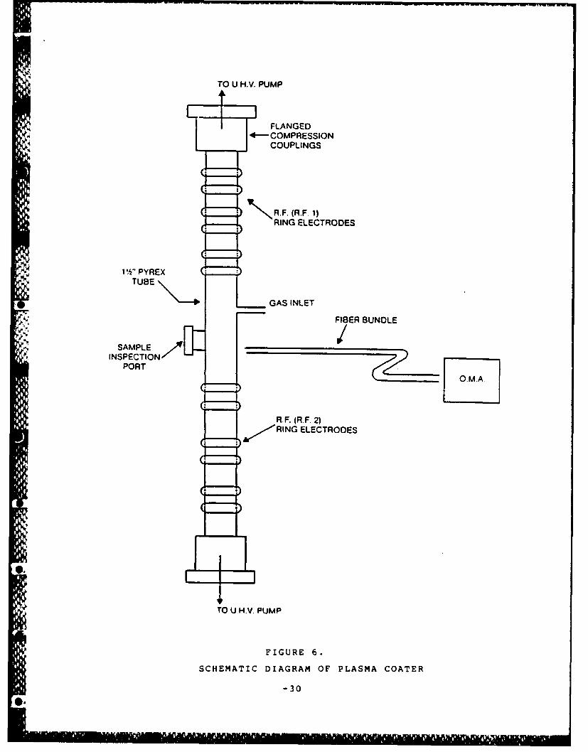
The hollow cathode coater was replaced with a
silica glass tube of the same length and sealed by means
of O-ring compression fittings. The tube wa: fitted
with two ports, one for the introduction of the reacting
gases, the other for pressure monitoring. A block
diagram of the overall system is given in Fig. 6. Two
low power (- 150 watts) RF generators (marked RF 1 and
2) were used to excite the gases within the coater. The
generators used were ordinary ham radio power supplies
operated in the 14 MHZ band. A commercial matching unit
was used with one of the transmitters allowing nearly
"-9-

100% coupling to the coater while a second matching unit
was constructed with available parts in-house and
typically provided 60% coupling to the coater.
Emissions from the discharge were monitored in real time
using the O.M.A. (optical multichannel analyzer). The
O.M.A. used was a P.A.R. 1452 plasma monitor consisting
of a 512 element Reticon scanned array mounted on a Y.A.
0.25 meter monochromator. The overall spectral
resolution of the system was on the order of 0.5 nm.
Because no pressure gauge was available at the coater,
it was impossible to know the actual pressure in the
coater. Instead, flow rates were measured and the
pressure assumed to vary proportionately.
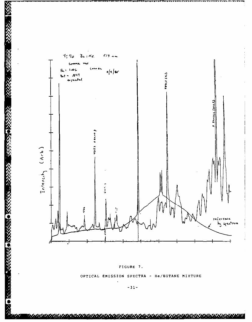
Several gas combinations were used. These were
various mixtures of butane/He, butane/Ar, acetylene/He,
freon/He and pure butane and acetylene. A typical
I. spectrum taken from a butane/He discharge is presented"I.
in Fig. 7. This spectrum is typical of the conditionsthat were found to lead to high deposition rates.
Basically, it consisted of well developed band sequences
extending over the entire visible region of the
spectrum. It was found that deposition rate increased
with increasing He/Butane ratio. Atomic hydrogen lineswere prominent in the spectra of these high deposition
mixtures. The vast majority of the bands remain
unidentified however.
-i0-
4.V

Qualitatively, these results are easily understood.
Electrons are produced by impact ionization of the gas.
In the case of He, the process may be expressed:
He + e- 4 He + 2e- -- (1)
For the butane, we have a number of possible steps:
O 140 + e- C4 H 9+ + 2e-
* C 4 H8 + H+ + 2e- -- (2)
SC4 H8 + H + 2e-
4other fragments + 2e
As the partial pressure of butane is dropped, the
probability of the ionization becomes dominant. In this
case then, the types of fragments produced are
determined by the results of collisions of the type
He+ + C4H10 H He + fragments+ -- (3)
Since the ionization potential of He is quite large
(> 580 kcal/mole), the results from (3) can be rich in
highly reactive free radical fragments which can then
undergo reactions at any surface they may encounter.
Thus, the main feature of the data could be
-11-
I',
CI n -- WV
explained. As the partial pressure of butane was
decreased, impact ionization of the helium (equation 1)
became dominant and subsequent ion-molecule reactions
(equation 3) became the principal mechanism of formation
of butane fragments. Among these fragments was atomic
hydrogen which accounted for the observed Balmer lines.
The deposition rate increased due to abundance of
reactive fragments. Deposition from both helium-butane
and argon-butane mixtures showed the same behavior. The
best deposition rate was obtained with a 1%
helium-butane mixture which gave 400 A/min.
Deposition from acetylene was remarkably different.
The spectrum of a pure acetylene discharge is shown in
Fig. 8. As is evident here, the spectrum shows a strong
atomic hydrogen component. Furthermore, a sequence of
bands appear to the blue of the H-Balmer a-line which
have the appearance of a predissociation spectrum. All
efforts to identify these bands from the literature
failed to provide positive identification. The
deposition rate was found to be largest for acetylene
discharges at relatively low pressures. The highest
rate was found to be of order of 450A/min.
A number of bulk samples were coated with a-C:H
including microscope slides, NaCl plates, ZBLAN fluoride
glass and sapphire blanks. IR transmission spectra was
-12-

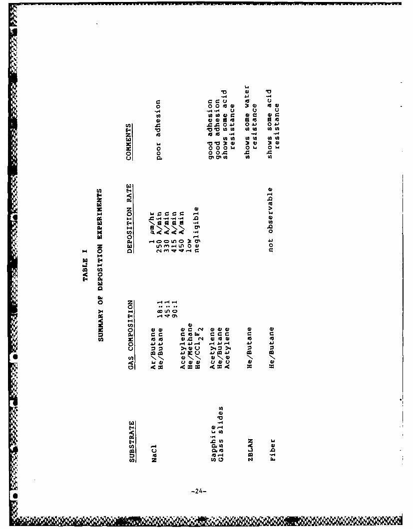
collected in many of these cases. Table I gives a list
of the gases and gas mixtures used along with the
observed deposition rates and appropriate comments. A
number of conclusions could be drawn from these
experiments.
It was evident that a-C:H films could be deposited
from collisionally controlled plasma glow discharges.
Helium was a better buffer gas than argon and led to
higher deposition rates. It was not clear whether this
was due to better coupling of the RF in helium or due to
more efficient ion-molecule reactions. Similarly,
butane provided higher deposition rates than did
methane.
Attempts to use fluorinated compounds were not
successful, although it is not clear why this should be
the case. The fluorinated species are strongly
electronegative and no doubt form negative ions.
Whether they were in some way inhibiting a-C:H formation
would be total speculation at this stage.
Finally, the acetylene discharge was interesting.
Clearly significant fragmentation (as evidenced by both
atomic hydrogen lines and the apparent predissociation
bands) was taking place independent of buffer gas.
-13-

Analyses of the films were made in several
different ways. For sufficiently thick films, the SEM
could be used to determine both film thickness and
composition. In the best case, only C, Si and 0 could
"be identified. Fig. 9 shows the spectrum of a film
deposited from 90:10 He: Butane gas mixture. In other
cases, a number of trace impurities such as Na, Mg, Al,
etc. were detected but these appear to be part of the
substrate material. The SEM could provide no
information on the structure of the films and was unable
to detect atomic hydrogen which could be as much as 30
at. % of the film. In all cases, the films were
non-conducting (as determined using an ohm meter) and
had a brown tint to them.
Infrared transmission spectra in the 2-10pm range
were obtained using an FTIR spectrometer. The spectra
were found to be similar to that reported by others. A
typical spectrum is shown in Fig. 10. The bands near
3.5pm are due to C-H stretch and have been observed in
a-C:H films produced by other means of deposition. The
bands between 6pm and 10pm are mainly due to impurities
except that near 7.4pm, it may be C-C stretch.
Figure 11 shows the C-H band expanded. Bubenzer et.al.
analyzed the structure of this band and obtained the
relative contributions of sp2 (graphite-like) and sp 3
(diamond-like) bonding in their film. A similar
-14-
analysis of film deposited at SpecTran indicates - 50%
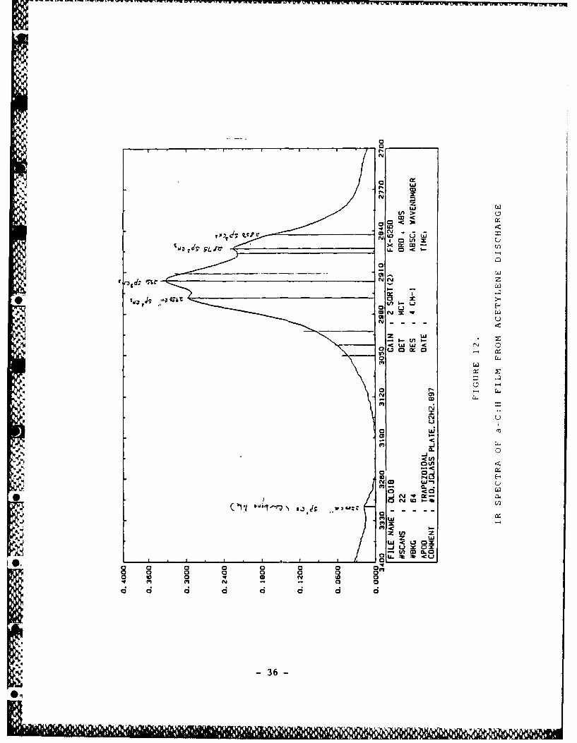
sp3 character. A typical transmission spectrum derived
from a film deposited from pure acetylene discharge is
shown in Fig. 12. Aside from the bands near 2900 cm- 1 a
weak band was observed at 330 cm-1 corresponding to C-H
stretch on spI bonded carbon (carbyne like). This
spectrum is very similar to what has been observed by
Bubenzer et.al. using benzene in a self biased
discharge.
Resistance to various solvents and to HF had been
tested with a number of these films. In some cases, for
example, for a film deposited from an acetylene
discharge on a sapphire substrate, adhesion proved to be
quite good. For these cases, films easily passed an
adhesive tape test, could be cleaned with solvents, and
rubbed vigorously with lab tissue. It was often the
case however that thick films would not show such
adhesion. It was also found that HF would not wet the
surface of the films and had no observable effect on the
films even after several hours. It was observed,
however, that after - 1 hour of HF exposure, the film
would lift in some places. This was probably due to the
existence of pinholes in the film through which the HF
penetrated and attacked the substrate underneath.
During the period March 1985 to September 1985,
-15-

efforts were directed towards coating fibers with a-C:H
films with the plasma coater used for bulk deposition
experiments. Initial attempts to draw the fiber with
the vacuum system and coater fully assembled yielded
very weak fiber. The fiber when stressed would break in
many pieces. Inspection of the glass under a microscope
revealed severe scratches caused by contact with one or
more of the 4mm differential pumping ports. Alignment
of these ports had been critical to fiber draw and view
ports had been added at several points to permit careful
alignment. Inspection of one of the sections not fitted
with a view port revealed alignment problems which, when
corrected, immediately led to drawing good strength
fiber. Figure 13 shows a typical Weibull plot generated
from data on tensile testing of uncoated control fibers.
Median strengths were in the range of 700-750 kpsi. The
plasma coater was then operated to deposit thin films of
a-C:H on the fiber under dynamic conditions. Draw speed
was typically between 5-10 meter/min. The vacuum was
maintained between 0.1 to 0.3 Torr. An He: acetylene
mixture was used. For all cases the fiber was visibly
coated with a light brown deposit.
Sl.
Analysis of the fiber proceeded as follows. A
- number of breaks were made using a 0.5 meter gauge
length fiber in the Instron dynamic fatigue tester.
After - 20 breaks at each of two strain rates two orders
-16-U,
.A. )

of magnitude apart, a stress corrosion coefficient was
evaluated. Because the break distribution was quite
wide, the values of the stress corrosion coefficient
showed a wide variation. But the best estimate of N
value with a-C:H coatings was 26, which showed that
a-C:H were ineffective so far as hermeticity was
concerned. Figure 14 presents the Weibull plots of
a-C:H coated fibers tensile tested at two different
strain rates. The reason for this lack of hermeticity
may be the columnar structure of these coatings. A
scanning electron photomicrograph on a-C:H coating
clearly shows the columnar nature of film growth.
Figure 15 shows a typical example.
To improve upon the moisture barrier properties
further, a few other materials were explored as
potential hermetic coatings.
Amorphous Si:H coatings were deposited on the fiber
using the plasma coater. Gaseous silane was used as the
precursor material instead of a hydrocarbon. The
coating was quite transparent in the infrared
wavelengths and had a refractive index of approximately
4.0. It was a good insulator but provided no hermetic
protection.
Attempts were made to deposit silicon carbide,
-17-
4 ,

titanium carbide, silicon nitride and boron nitride on
fibers by the plasma technique. For silicon carbide, a
mixture of silane and acetylene was fed into the plasma
coater. A hard coating was obtained and an N value of
as high as 60 resulted. Figure 16 presents the data in
the form of Weibull plots.
For silicon nitride deposition, a mixture of silane
and nitrogen was used. Fiber drawn at up to 19
meters/minute showed hermetic protection with a stress
corrosion coefficient, N-75. Results are shown in
Fig. 17.
Initial work with titanium carbide deposition from
a mixture of TiC1 4 and acetylene led to serious plasma
instability problems. Black sooty deposit was obtained
on the fiber. Boron nitride could be easily deposited
from a mixture of diborane and nitrogen. The diborane
was diluted in hydrogen and, therefore, no inert carrier
gas was required. While BN did not show any hermetic
protection (N-18), it seemed to provide the fiber with a
scratch resistant surface.
I3.0 CONCLUSIONS:
Initial efforts in this contract were directed
towards coating of fiber with a-C:H by the hollow
-18-
4

cathode magnetron approach. One such coater was
designed and implemented on a draw tower. But it was
found that the coater was subject to severe arcing. The
electrodes were rapidly eroded. Fiber was essentially
found to be coated with impure graphite with only very
slight improvement in static fatigue parameter.
After careful review of the coater design, it was
concluded that the large aspect ratio (length of cathode
divided by inside diameter) of the coater led to
discharge instability. A solution to this problem might
have been the use of a series of small L/D ratio
coaters. Since each of these coaters would have had to
be operated under low vacuum, the fiber would have had
to pass through that many more entry and exit vacuum
ports. This would have increased the problem of
aligning the system and all the ports - a critical
necessity for making fibers with high strength.
To address some of these problems and to make the
deposition system easily operable and maintainable, the
hollow cathode apparatus was replaced by a low pressure
RF plasma coater. Collisionally controlled plasma
discharges in hydrocarbons were successfully used to
deposit a-C:H films. There was no need for biasing the
substrate or in any way controlling the ion energy to
obtain films with desirable properties. The coater used
IL -19-
in these experiments was far simpler than the hollow
cathode device it replaced and certainly much cheaper to
maintain. Deposition rates as high as several angstroms
per second were achieved.
Much of the effort was dedicated towards drawing
optical fiber with this a-C:H coating in a continuous
fashion. Fibers could be successfully coated with
diamond-like carbon. But the coating did not provide
the necessary hermeticity as was seen from the low N
value. The reason for this may be the columnar
structure of these coatings. A possible solution to
this problem may be to increase the coating thickness by
extending the plasma coater length. Height limitations
at the time of this contract precluded extension of the
coater length.
Several other materials besides a-C:H were
evaluated as potential hermetic coatings. These were
* a-Si:H, silicon carbide, silicon nitride, titanium
carbide and boron nitride. Both the carbides and
silicon nitride showed promise as potential hermetic
coatings for fiber by the plasma approach. N values as
high as 70 were obtained with silicon nitride.
Further investigations with materials like silicon
nitride, silicon carbide or titanium carbide were
-20-

indicated by this work. These materials appeared to be
promising as potential hermetic coatings for optical
fibers. The work done during this contract also
demonstrated the viability of adopting the RF plasma
deposition as a process easily compatible with the
conventional optical fiber draw technology.
Although the original hollow cathode discharge
technique failed to produce diamond-like carbon and was
abandoned in favor of the RF excitation approach, and
even though the RF excitation approach could produce
diamond-like carbon with only low N value, the program
did demonstrate:
(a) the feasibility of direct interfacing of a draw
furnace and vacuum coater;
(b) the feasibility of increasing the sizes of entrance
and exit orifices of the deposition chamber to
produce undamaged control and coated fiber;
(c) the feasibility of using RF discharge in producing
diamond-like carbon;
(d) the applicability of RF discharge technique to several
chemistries capable of providing hermeticity;
(e) possibility of using RF discharge technique to
apply hermetic coatings at low temperatures;
and (f) potential use of RF deposition technique to apply
hermetic coatings on an important class of glass
optical fibers - heavy metal fluorides.
-21-
IdE

REFERENCES
1. Wysocki, J., "Reduction in Static Fatigue of Silica Fibers byHermetic Jacketing", Appl. Phys. Lett., 34 (1), Jan. 1979.
2. Hanson, E. et.al., "High Strength Hermetically Coated OpticalFiber", Report on Naval Ocean Systems Center ContractNo. N 00123-80-C-0245.
3. Hanson, E., et.al., U.S. Patent No. 4,512,629.
4. Kao, C., U.S. Patent No. 4,183,621.
5. Ray Chaudhuri, S. and P. C. Schultz, "Hermetic Coatings onOptical Fibers", Paper No. 717-19, SPIE Conference, Sept.21-26, 1986, Cambridge, MA.
6. Stevens, J. M., Stein, M., and Jaeger, R. E., "Carbon CoatedOptical Fibers", - Proceedings of the DARPA Workshop onDiamond-like Carbon, April 19-20, 1982, Albuquerque, NewMexico.
7. Stein, M., "Ion Plasma Deposition of Carbon-Indium HermeticCoatings for Optical Fibers", Proceedings of Conference ofLaser and Electro-Optics, June 10-12, 1982.
8. Ritter, J. E., Sullivan, J. M., and Jakus, K. - "Applicationof Fracture Mechanics Theory to Fatigue Failure of OpticalGlass Fibers", - Jr. Appl. Phys., 49 (9), Sept. 1978.
9. Vossen, J. L. and Kern. W., - "Thin Film Processes", AcademicPress, New York.
10. Mort, S. and Jansen, F., - "Plasma Deposited Thin Films", -CRC Press, Boca Raton, Florida.
11. Dishler, B., Bubenzer, A., and Koidl, P., in Solid StateComm., 48, 105, (1983)
-22-
0.
LIST OF TABLES AND FIGURES
TABLE 1: Summary of Deposition Experiments
FIGURE 1: Overall View of the Hermetic Coating Apparatus
FIGURE 2: Schematic Diagram of the Coater
FIGURE 3: Fiber Coating Analysis
FIGURE 4: Dynamic Fatigue Plot - Coated Fiber
FIGURE 5: Dynamic Fatigue Plot - Uncoated Fiber
FIGURE 6: Schematic Diagram of Plasma Coater
FIGURE 7: Optical Emission Spectra - He/Butane Mixture
* FIGURE 8: Optical Emission Spectra - Acetylene Discharge
FIGURE 9: SEN Analysis of Carbon Film
FIGURE 10: IR Spectra a-C:H Film
FIGURE 11: C-H Band Stretch - IR Spectra
FIGURE 12: IR Spectra of a-C:H Film From Acetylene Discharge
FIGURE 13: Weibull Plot of Control Fiber
FIGURE 14: Weibull Plots of a-C:H Coated Fiber at Two StrainRates
FIGURE 15: Scanning Electron Photomicrograph of a-C:H CoatedFibers
FIGURE 16: Weibull Plots of SiC Coated Fibers
FIGURE 17: Weibull Plots of Si 3 N4 Coated Fibers
-23-
4..1
.... ..-44 u
o)d 000to 0 0Ua
0 C 10 41 0Aj 0A
E-410 1010 tOI IA 4 o)
0 o00w 0M 0ow
0 0 0 0. .
040
E-.4
E-4Uzz
W E- 0~.i,.4. .0 9*11- Nul "1 . U)
oc 0
H 0 C4~
0
o cZ0-
0 00 0i 0
go) 4)0 = " 4) o0 1A - W ý 4Jq. *J.)j ý4 Ai 4
En N0 00 00N 0 0ý 0
U)
E-44
U) -4 4)U 0
10~t 0 ~ 0 ~ .
-24-

FURNACE AND ADAPTOR PLATE
DIAMETER MONITOR VIEW PORT
ROUGH VACUUM PUMPING PORT
S~HIGH VACUUM PUMPING PORT
•" • ~UPPER ANODE ASSL'Y--
COATER SECTION
Ill~i:4 • LOWER ANODE ASSL'Y _• •
IILOWER HI-VACPUMPING PORT
SIROUGH VACUUM PUMPING
PORTS TO U.HV.
PUMPTEFLON EXIT PORT
FIGURE 1 .
Overall View of the Hermetic Coating Apparatus
5-25-TEFLON~~ NXTPR
, 4mm APERTURE
,7 ,7 4 -UPPER ANODE
(GROUNU)
!, 0
GAS INLET 0
HOLES 0
o
0V 0
00°0o0
-a 0
J0
I 00 GRAPHITE HOLLOW
0 CATHODE
0 (-V)I 0a a
0 21"a II 0
o Ia 0
0
0
00
0
0 ao
o
O LOWER ANODE
LL, (GROUND)
' 4mm APERTURE
FIGURE 2.
SCHEMATIC DIAGRAM OF THE COATER
-26-

r Li
(L2
ul
L W
0 ILL
tucC
27:
DO
CO,wIco
< 0WLL> X-
-w C
*j oz
cc >-< c
C/)oL c
<I E-
F- *
0 z
m~ cci
SS3UIS~uflIOV~d= NVIGB3V' UI
wm<
0
LL u0w <
< z E< 00n
w - -
LL C-4% u~ -
<1
040
LO qTC?)
SS3HIS 3uflOVH~d NVIGCV'J Ul
-29 -
TO U.H.V. PUMP
FLANGED*- COMPRESSION
COUPLINGS
SR.F. (R.F. 1)RING ELECTRODES
1 '* PYREX
TUBE L GAS INLET
FIBER BUNDLE
"SAMPLEINSPECTIONZ
PORT5O.M.A.
R.F. (R.F. 2)SJRING ELECTRODES
9.
TO UH.V. PUMP
FIGURE 6.
SCHEMATIC DIAGRAM OF PLASMA COATER
-30
1f .0 1. , 21 ja.r/ . .,
bat - ,;
°C.
.'tA
''
f-4-
'o0, FIGURE 7 .
• "JOPTICAL EMISSION SPECTRA -He/BUTANE MIXTURE
-- • --31--
I.

-32-

CARBON FILMi ON GLASS SLIDE #4
SPECTRUI LABEL SPECTRUM~ FILE NAMIE
m LCI4;21.5u ARO95A
1200
CARBON
~ t FILM THICKNESS ESTIMATED
I ~AT 2.~5 MICRONS
II r
4~0
0.0 ~~1.0". 0
ENERGY hI:EV)
FIGURE 9.
SEM ANALYSIS OF CARBON FILM
-33

0
Ln :
o w
0 a
0
A NN N
u o ; o C
LLr.n E-_
* _ U -
N u•
0 tn
m
a3 -C3 -J
-U
Ow
0 w
010
wl m
0 0 0 0
-34 -

CY
0 tN
CO0
Ir I co
a -'N(A LW
o 2cy x-U
N Li -
N3 Lx7 ..
0 t0a r-
c i2
l-J
0. -i
o LI<
-J<0Ow
0 CL
N <LU
in w
w < (3 0X.. i u 02o
IN LL. % 4h CL
0~ f 0n0 a
-35-
V0 >CZ)
03
10 V)
7~ LA.
zi w
in u
co uoY - -
oC w w
0.
EIn01
(0 E-
I')CL
10 U O
0
w < U ox

1.000--
0o
13
00
0.0100
DYNMI FAIU TENTKS
z0 o
SI I I I I I I
FIGURE 13 .
WEIBULL PLOT OF CONTROL FIBER
-37-
"0

1.000
r
o 0lo 0o 03
0 0
0.10 0 0
E30
11
0.010
100 200 400 500 Go0 700 a0 900 1000
DYNAMIC FATIGUE STRENGTH, KPSI
FIGURE 16.
WEIBULL PLOTS OF SiC COATED FIBERS
-40-

1.00- -0
o Ll0 L]0 L-1o Ll
00
-- 41-

77 7 -t.. ... N %
MISSIONOf
* ARome Air Development CenterRAVC pta~n6 and excutes 'reseaLc~h, devetopment, tes-tand 6eZec-ted acquisition ptogtamz i~n scuppoJL o6
*Command, Con~toZ, Communicati.ons and In~teZZtLgencea' c~ zt.Lv.L* 'Ies5. Tzchn.-*ai and eflginbeeti..ng
.5Luppoý'Lz wA.4-tku.n atea45 o6 c~ompetenc~e is pýLuv-aea ZUESO PPtogt'am O66ies~ (PO.s) and othet ESO etemen-t4
I -~~to pv'c.o'tm e66ec.tive ac~quisition o6 C3 1 6sy-~tem4.The a'Lea4 o6 tec~hnicat competCence -LncZu~decomnctos command and con~t~ot, battte
*managemen~t, in6otrma~t.on ptoce64ing, 6utve.LZtance65en~ot4, in~tetti~gence da~ta cottecti~on and handti~ng,
* 6c'ZA.d -6tate sciLenes.~, etectt~omagne~tic6, andr~opagation, and eteettionic, main~tainabiti~ty,aind comnpat.Lbi~..ty.
L "Vol