Hermetic Centrifugal Liquid Chiller - CARRIERcarrier.com.hk/comm/comm_new2010/2013 Cat/Water...
28
19XR/XR-E Hermetic Centrifugal Liquid Chiller Cooling Capacity:19XR 300~1650TR 19XR-E 800~1500TR
Transcript of Hermetic Centrifugal Liquid Chiller - CARRIERcarrier.com.hk/comm/comm_new2010/2013 Cat/Water...
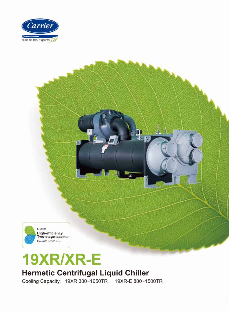
19XR/XR-EHermetic Centrifugal Liquid ChillerCooling Capacity:19XR 300~1650TR 19XR-E 800~1500TR
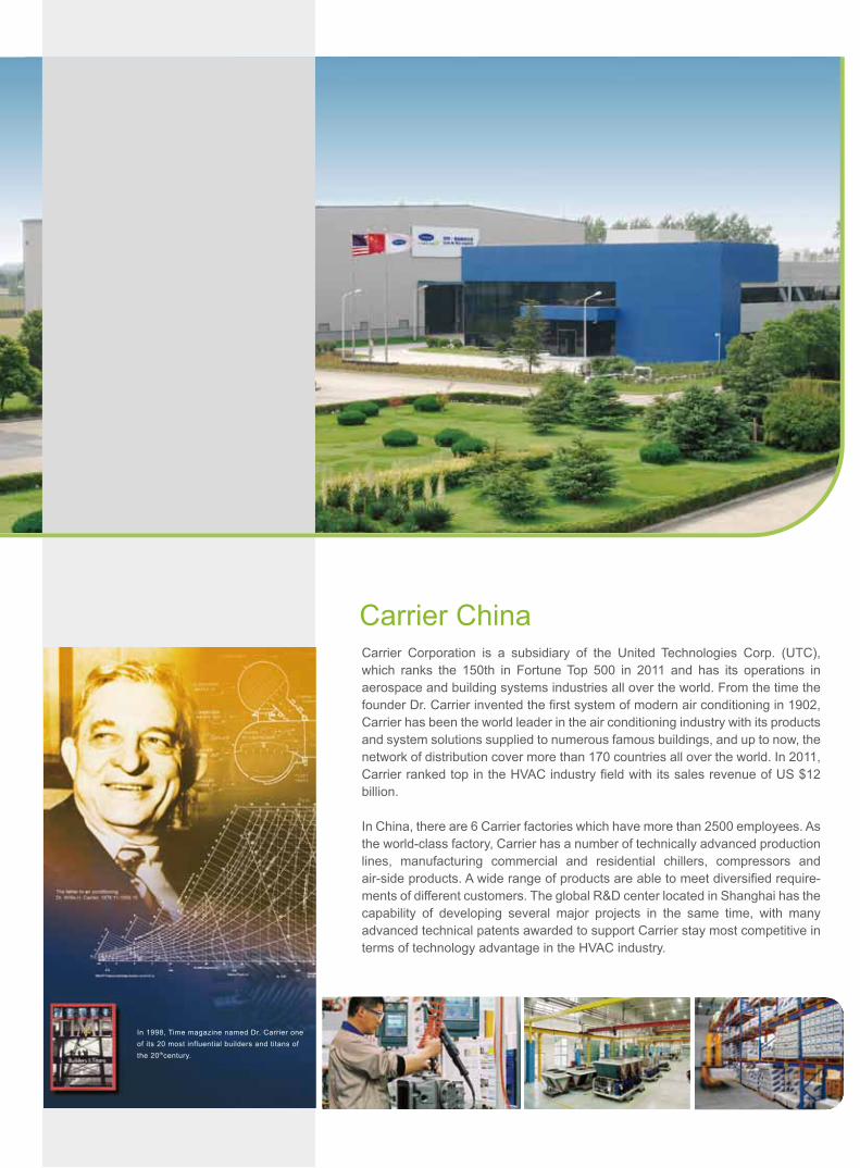
Carrier Corporation is a subsidiary of the United Technologies Corp. (UTC), which ranks the 150th in Fortune Top 500 in 2011 and has its operations in aerospace and building systems industries all over the world. From the time the founder Dr. Carrier invented the first system of modern air conditioning in 1902, Carrier has been the world leader in the air conditioning industry with its products and system solutions supplied to numerous famous buildings, and up to now, the network of distribution cover more than 170 countries all over the world. In 2011, Carrier ranked top in the HVAC industry field with its sales revenue of US $12 billion.
In China, there are 6 Carrier factories which have more than 2500 employees. As the world-class factory, Carrier has a number of technically advanced production lines, manufacturing commercial and residential chillers, compressors and air-side products. A wide range of products are able to meet diversified require-ments of different customers. The global R&D center located in Shanghai has the capability of developing several major projects in the same time, with many advanced technical patents awarded to support Carrier stay most competitive in terms of technology advantage in the HVAC industry.
Carrier China
In 1998, Time magazine named Dr. Carrier oneof its 20 most influential builders and titans ofthe 20thcentury.

Model Number Nomenclature
Cooling Capacity
Note: Carrier is dedicated to continuous product development. Components list will vary to meet different demands*Availability please check with local sales office
19XR:1055~5274kW (Air condition Low voltage/Middle votage) 2110~5803kW (Air condition High voltage) 1055~5135kW (Air condition Low voltage VFD)19XR-E:2813~5274kW (Air condition Low voltage/Low voltage VFD/Middle voltage/High voltage) 2110~3517kW (Ice condition Low voltage/Middle voltage/High voltage)
2
19XR 65 65 467 DJ S 52
Description19XR-High Efficiency HermeticCentrifugal Liquid Chiller
19XRV-Ultra High EfficiencyHermetic Centrifugal Liquid Chillerwith VFD19XR-E-Two-stage High EfficiencyHermetic Centrifugal Liquid Chiller19XRV-E-Two-stage Ultra High Efficiency Hermetic Centrifugal Liquid Chiller with VFD
Cooler Size30, 31, 3235, 36, 3740, 41, 4245, 46, 4750-54, 5P-5R55-59, 5X-5Z60-64, 6P-6R65-69, 6X-6Z70-74, 7P-7R75-79, 7X-7Z80-84, 8P-8R85-89, 8X-8Z
Compressor CodeFirst Digit Indicates Compressor Frame Size
Motor Voltage Code52-(380V-3Ph-50Hz)55-(6.3kV-3Ph-50Hz)5A-(10k52-400-3-5053-3000-3-5054-3300-3-5055-6300-3-505A-10000-3-505B-11000-3-5062-380-3-6063-416-3-6067-3300-3-6068-4160-3-6059-6900-3-606A-11000-3-60
V-3Ph-50Hz)
Motor Efficiency CodeS - Standard EfficiencyH - High EfficiencyGear size code for 19XR-E
Condenser Size30, 31, 3235, 36, 3740, 41, 4245, 46, 4750, 51, 52, 53, 5455, 56, 57, 58, 5960, 61, 62, 63, 6465, 66, 67, 68, 6970, 71, 72, 73, 7475, 76, 77, 78, 7980, 81, 82, 83, 8485, 86, 87, 88, 89
Motor CodeCDCECLCMCNCPCQ
DCDDDEDFDGDHDJ
EHEJEKELEMENEP
MDMF

Energy-saving and High Efficiency
Stable Operation
Environmental Leadership
Compressor key components designed with advanced jet engine technology.Aerodynamically contoured impellers - Impellers use high back sweep main blades with low-rent and are smaller and lighter than profile intermediate splitter blades. This new design is aerodynamically contoured to improve compressor full-load and part-load operating efficiency.High performance tubing - Tubing with internally and externally enhanced fins improves chiller performance by reducing overall resistance to heat transfer. The new heat exchanger reduces refrigerant charge and manufacturing cost.Carrier patent AccuMeterTM system regulates refrigerant flow according to load conditions, provides a liquid seal at all operating conditions and eliminates unintentional hot gas bypass.Optimized piping design reduces refrigerant pressure loss and ensures chiller efficiency.
Variable inlet guide vanes - The guide vanes are connected with air-water piping,reducing installation craft-quality cable and controlled by a precise electronic actuator.The vanes regulate inlet flow to provide high efficiency through a wide operating range.Diffuser design - single-stage compressor utilizes patented SRD actuator to improveefficiency and reliability. Two-stage compressor utilizes vaneless diffuser to meet highlift application requirement with stable operation.
Designed specifically for chlorine-free HFC-134a refrigerant(the environmentally preferred HFC-134a refrigerant withzero-ozone-depletion potential)
SRDactuator
outerring
innerring
3

Advanced Design
Convenient Installation
Water boxes are equipped with standard flanges, which facilitate the field installation and protect temperature sensor.The positive pressure design reduces the chiller size by up to 35% compared to low-pressure design. The smaller size minimizes the need for valuable mechanical room floor space. In addition, positive-pressure design eliminates the need for additional cost of low-pressure containment devices.Refrigerant-cooled oil cooler-Refrigerant cooling eliminates field water piping, reduces installation cost.Cooler and condenser are designed and manufactured in accordance with the standard of pressure vessel of china. The unit isolation valves make the heat exchangers into a liquid containers and the pump out system is also provided to output refrigerant, which provides ease of maintenance.
International Chiller Visual Control (ICVC) -a large english LCD (liquid crystal display) features 4 menu-specific soft keys. The default display offers all in one glance review of key chiller operation data, simplifying the interaction between chiller and user.Direct digital Product Integrated Control (PIC II)- Automated controls test can be executed prior to start-up to verify that the entire control system is functioning properly. Carrier’s PIC II integrates directly with the Carrier Comfort Network (CCN) via DATAPORT module, providing a system solution to controls applications.Carrier offers 19XR/XR-E 10/11kV hermetic centrifugal chiller to provide more choices for installation with 10/11kV and power supply.19XRV/XR(V)-E Evergreen chiller equipped with a LF2 VFD that designs with total harmonic distortion (THD)<5% and fully meets IEEE519-1992 requirement. The 19XRV/XR(V)-E becomes a more cost-effective choice for installations with a high percentage of time operating at part load.Mix-match capability - The chillers provide a complete line of compressors, motors and heat exchangers, ensuring the best combination of chiller components regardless of tonnage, lift, and efficiency specifications.
4
Free-standing VFD starter Unit-mounted VFD starter
Environmental Leadership
Industry-leading Efficiency
The system has been designed specifically for chlorine-free HFC-134a refrigerant, the environmentally preferred HFC-134a refrigerant with zero-ozone depletion potential.
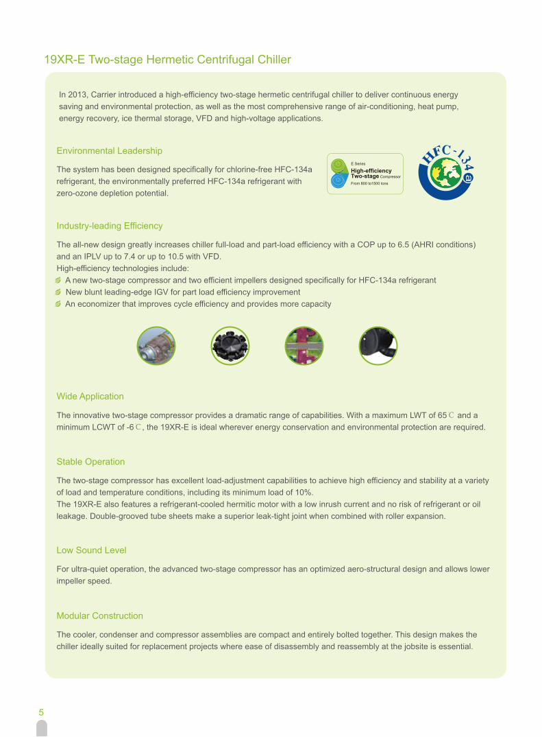
The all-new design greatly increases chiller full-load and part-load efficiency with a COP up to 6.5 (AHRI conditions) and an IPLV up to 7.4 or up to 10.5 with VFD.High-efficiency technologies include: A new two-stage compressor and two efficient impellers designed specifically for HFC-134a refrigerant New blunt leading-edge IGV for part load efficiency improvement An economizer that improves cycle efficiency and provides more capacity
Wide Application
The innovative two-stage compressor provides a dramatic range of capabilities. With a maximum LWT of 65℃ and a minimum LCWT of -6℃, the 19XR-E is ideal wherever energy conservation and environmental protection are required.
Stable Operation
The two-stage compressor has excellent load-adjustment capabilities to achieve high efficiency and stability at a variety of load and temperature conditions, including its minimum load of 10%.The 19XR-E also features a refrigerant-cooled hermitic motor with a low inrush current and no risk of refrigerant or oil leakage. Double-grooved tube sheets make a superior leak-tight joint when combined with roller expansion.
Low Sound Level
For ultra-quiet operation, the advanced two-stage compressor has an optimized aero-structural design and allows lower impeller speed.
Modular Construction
The cooler, condenser and compressor assemblies are compact and entirely bolted together. This design makes the chiller ideally suited for replacement projects where ease of disassembly and reassembly at the jobsite is essential.
In 2013, Carrier introduced a high-efficiency two-stage hermetic centrifugal chiller to deliver continuous energy saving and environmental protection, as well as the most comprehensive range of air-conditioning, heat pump, energy recovery, ice thermal storage, VFD and high-voltage applications.
a19XR-E Two-stage Hermetic Centrifugal Chiller
5

Geothermal Underground water
Earth's surface water Dark/Grey water
chiller cooling
Ice melting Ice Thermal Storage
Time 7 8 9 10 11 12 13 14 15 16 17 18 19 20 21 22 23 0 1 2 3 4 5 6
Heat Pump Application
The heat pump system utilizes natural energy storage in soil, bedrock, groundwater, surface water, wastewater and air to satisfy demand for building cooling, heating and hot water.
Heat Pump System Benefits Cooling/heating Improved system efficiency Use of low-grade energy
19XR-E Benefits Wide range of applications with high efficiency Hot water temperature (LWT) up to 65℃
Energy Recovery Application
Discharging condenser heat via a cooling tower not only causes thermal pollution but is a tremendous waste for locations with high demand for heating, such as hotels, factories and hospitals.
Energy Recovery System Benefits Reduced boiler size and operating time Reduced cooling tower size and waste heat discharge Improved system efficiency by 15-25%
19XR-E Benefits High efficiency operation Hot water temperature(LWT) up to 65℃
Ice Thermal Storage Application
The chiller stores energy as ice during the night, when electricity costs and utilization are low. This energy is then discharged to satisfy cooling loads when electricity costs peak during the day, greatly reducing building operating costs.
Ice Thermal Storage System Benefits Reduced chiller and cooling tower size Reduced chiller operating time Operational cost savings by using off-peak electricity Backup cooling in emergency situations
19XR-E Benefits Stable 24-hour operation Suitable for variable voltage and VFD applications Minimum leaving water temp (LCWT): -6℃ Suitable for cold air distribution district cooling systems
6
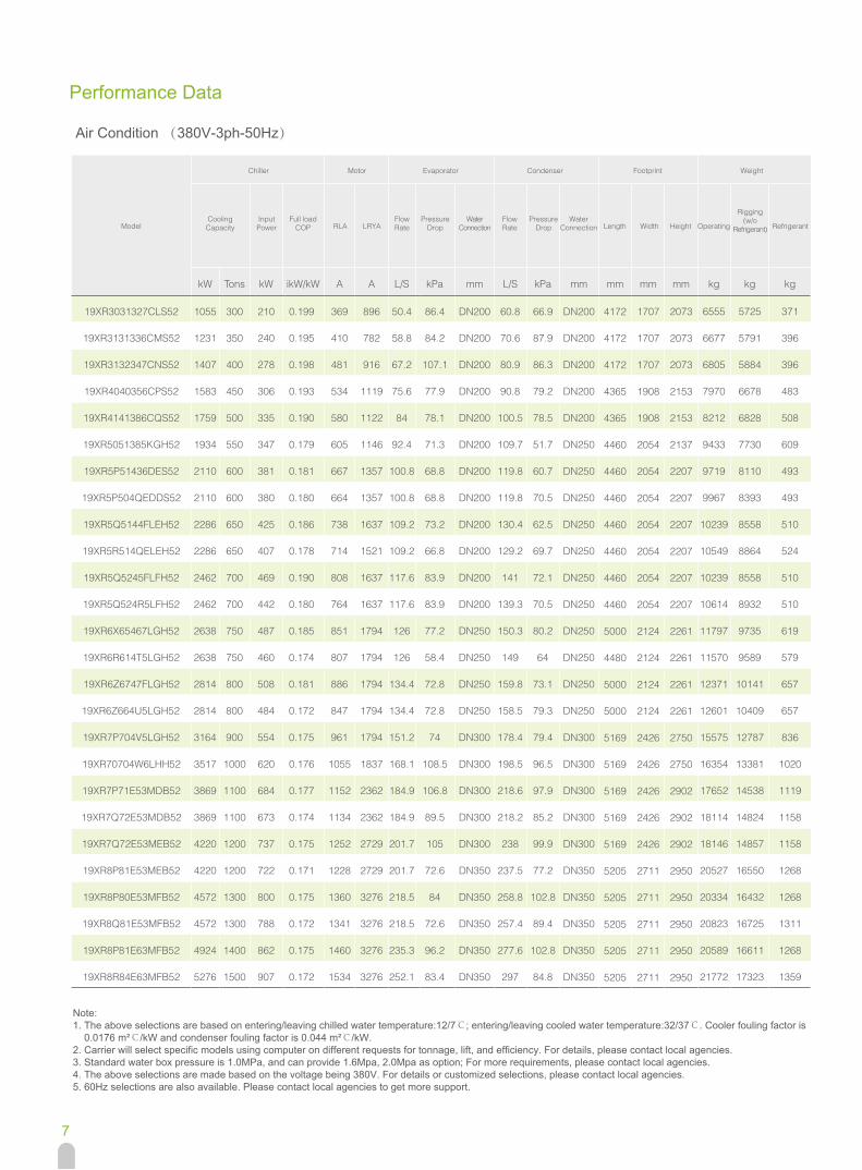
Performance Data
Air Condition (380V-3ph-50Hz)
Note:1. The above selections are based on entering/leaving chilled water temperature:12/7℃; entering/leaving cooled water temperature:32/37℃. Cooler fouling factor is 0.0176 m²℃/kW and condenser fouling factor is 0.044 m²℃/kW.2. Carrier will select specific models using computer on different requests for tonnage, lift, and efficiency. For details, please contact local agencies.3. Standard water box pressure is 1.0MPa, and can provide 1.6Mpa, 2.0Mpa as option; For more requirements, please contact local agencies.4. The above selections are made based on the voltage being 380V. For details or customized selections, please contact local agencies.5. 60Hz selections are also available. Please contact local agencies to get more support.
Model
Chiller Motor Evaporator
CoolingCapacity
InputPower
Full loadCOP RLA LRYA
FlowRate
PressureDrop
WaterConnection
FlowRate
PressureDrop
Condenser Footprint Weight
WaterConnection Length Width Height Operating
Rigging(w/o
Refrigerant) Refrigerant
kW Tons kW ikW/kW A A L/S kPa mm L/S kPa mm mm mm mm kg kg kg
19XR3031327CLS52 1055 300 210 0.199 369 896 50.4 86.4 DN200 60.8 66.9 DN200 4172
4172
4172
4365
4365
4460
4460
4460
4460
4460
4460
4460
5000
4480
5000
5000
5169
5169
5169
5169
5169
5205
5205
5205
5205
5205
1707
1707
1707
1908
1908
2054
2054
2054
2054
2054
2054
2054
2124
2124
2124
2124
2426
2426
2426
2426
2426
2711
2711
2711
2711
2711
2073
2073
2073
2153
2153
2137
2207
2207
2207
2207
2207
2207
2261
2261
2261
2261
2750
2750
2902
2902
2902
2950
2950
2950
2950
2950
6555 5725 371
19XR3131336CMS52 1231 350 240 0.195 410 782 58.8 84.2 DN200 70.6 87.9 DN200 6677 5791 396
19XR3132347CNS52 1407 400 278 0.198 481 916 67.2 107.1 DN200 80.9 86.3 DN200 6805 5884 396
19XR4040356CPS52 1583 450 306 0.193 534 1119 75.6 77.9 DN200 90.8 79.2 DN200 7970 6678 483
19XR4141386CQS52 1759 500 335 0.190 580 1122 84 78.1 DN200 100.5 78.5 DN200 8212 6828 508
19XR5051385KGH52 1934 550 347 0.179 605 1146 92.4 71.3 DN200 109.7 51.7 DN250 9433 7730 609
19XR5P51436DES52 2110 600 381 0.181 667 1357 100.8 68.8 DN200 119.8 60.7 DN250 9719 8110 493
19XR5P504QEDDS52 2110 600 380 0.180 664 1357 100.8 68.8 DN200 119.8 70.5 DN250 9967 8393 493
19XR5Q5144FLEH52 2286 650 425 0.186 738 1637 109.2 73.2 DN200 130.4 62.5 DN250 10239 8558 510
19XR5R514QELEH52 2286 650 407 0.178 714 1521 109.2 66.8 DN200 129.2 69.7 DN250 10549 8864 524
19XR5Q5245FLFH52 2462 700 469 0.190 808 1637 117.6 83.9 DN200 141 72.1 DN250 10239 8558 510
19XR5Q524R5LFH52 2462 700 442 0.180 764 1637 117.6 83.9 DN200 139.3 70.5 DN250 10614 8932 510
19XR6X65467LGH52 2638 750 487 0.185 851 1794 126 77.2 DN250 150.3 80.2 DN250 11797 9735 619
19XR6R614T5LGH52 2638 750 460 0.174 807 1794 126 58.4 DN250 149 64 DN250 11570 9589 579
19XR6Z6747FLGH52 2814 800 508 0.181 886 1794 134.4 72.8 DN250 159.8 73.1 DN250 12371 10141 657
19XR6Z664U5LGH52 2814 800 484 0.172 847 1794 134.4 72.8 DN250 158.5 79.3 DN250 12601 10409 657
19XR7P704V5LGH52 3164 900 554 0.175 961 1794 151.2 74 DN300 178.4 79.4 DN300 15575 12787 836
19XR70704W6LHH52 3517 1000 620 0.176 1055 1837 168.1 108.5 DN300 198.5 96.5 DN300 16354 13381 1020
19XR7P71E53MDB52 3869 1100 684 0.177 1152 2362 184.9 106.8 DN300 218.6 97.9 DN300 17652 14538 1119
19XR7Q72E53MDB52 3869 1100 673 0.174 1134 2362 184.9 89.5 DN300 218.2 85.2 DN300 18114 14824 1158
19XR7Q72E53MEB52 4220 1200 737 0.175 1252 2729 201.7 105 DN300 238 99.9 DN300 18146 14857 1158
19XR8P81E53MEB52 4220 1200 722 0.171 1228 2729 201.7 72.6 DN350 237.5 77.2 DN350 20527 16550 1268
19XR8P80E53MFB52 4572 1300 800 0.175 1360 3276 218.5 84 DN350 258.8 102.8 DN350 20334 16432 1268
19XR8Q81E53MFB52 4572 1300 788 0.172 1341 3276 218.5 72.6 DN350 257.4 89.4 DN350 20823 16725 1311
19XR8P81E63MFB52 4924 1400 862 0.175 1460 3276 235.3 96.2 DN350 277.6 102.8 DN350 20589 16611 1268
19XR8R84E63MFB52 5276 1500 907 0.172 1534 3276 252.1 83.4 DN350 297 84.8 DN350 21772 17323 1359
7

Performance Data
Air Condition (10kV-3ph-50Hz)
kW Tons kW ikW/kW A A L/S kPa mm L/S kPa mm mm mm mm kg kg kg
19XR7P704V5LHH5A 3164 900 556 0.176 38 200 151.2 74 DN300 179.3 80 DN300 5169
5169
5169
5169
5169
5205
5205
5205
5205
5205
5731
8032
8032
2426
2426
2426
2426
2426
2711
2711
2711
2711
2711
2712
3261
3261
2750
2750
2902
2902
2902
2950
2950
2950
2950
2950
3029
3365
3365
16192 13403 836
19XR70704W6LHH5A 3517 1000 620 0.176 42 200 168.1 108.5 DN300 198.5 96.5 DN300 16960 13985 1020
19XR7P71E53MDB5A 3869 1100 685 0.177 45 231 184.9 106.8 DN300 218.6 97.9 DN300 18195 15081 1119
19XR7Q72E53MDB5A 3869 1100 674 0.174 45 231 184.9 89.5 DN300 218.2 85.2 DN300 18657 15368 1158
19XR7Q72E53MFB5A 4220 1200 736 0.174 49 244 201.7 105 DN300 238 99.9 DN300 18563 15273 1158
19XR8P81E53MFB5A 4220 1200 721 0.171 48 244 201.7 72.6 DN350 237.5 77.2 DN350 20944 16967 1268
19XR8P80E53MFB5A 4572 1300 799 0.175 53 244 218.5 84 DN350 258.8 102.8 DN350 20689 16787 1268
19XR8Q81E53MFB5A 4572 1300 787 0.172 52 244 218.5 72.6 DN350 257.4 89.4 DN350 21178 17080 1311
19XR8P81E63MFB5A 4924 1400 861 0.175 57 244 235.3 96.2 DN350 277.6 102.8 DN350 20944 16967 1268
19XR8R84E63MFB5A 5276 1500 906 0.172 60 244 252.1 83.4 DN350 297 84.8 DN350 22127 17678 1359
19XR878750EMHH5A 5803 1650 988 0.170 64 299 277.3 148.1 DN350 326.1 135.7 DN350 24551 19955 1420
19XRD5QQQQ585585MFHMFH5A 8790 2500 1508 0.172 101 295 420.1 63 DN450 495.8 61.2 DN450 42230 35552 2266
19XRD5RRSS595595MFHMFH5A 10548 3000 1825 0.173 122 305 504.1 87.9 DN450 595.5 67.1 DN450 43498 36482 2206
Note:1. The above selections are based on entering/leaving chilled water temperature:12/7℃; entering/leaving cooled water temperature:32/37℃. Cooler fouling factor is 0.0176 m²℃/kW and condenser fouling factor is 0.044 m²℃/kW.2. Carrier will select specific models using computer on different requests for tonnage, lift, and efficiency. For details, please contact local agencies.3. Standard water box pressure is 1.0MPa, and can provide 1.6Mpa, 2.0Mpa as option; For more requirements, please contact local agencies.4. The above selections are made based on the voltage being 380V. For details or customized selections, please contact local agencies.5. 60Hz selections are also available. Please contact local agencies to get more support.
Model
Chiller Motor Evaporator Condenser Footprint Weight
CoolingCapacity
InputPower
Full loadCOP RLA LRYA
FlowRate
PressureDrop
WaterConnection
FlowRate
PressureDrop
WaterConnection Length Width Height Operating
Rigging(w/o
Refrigerant)Refrigerant
8
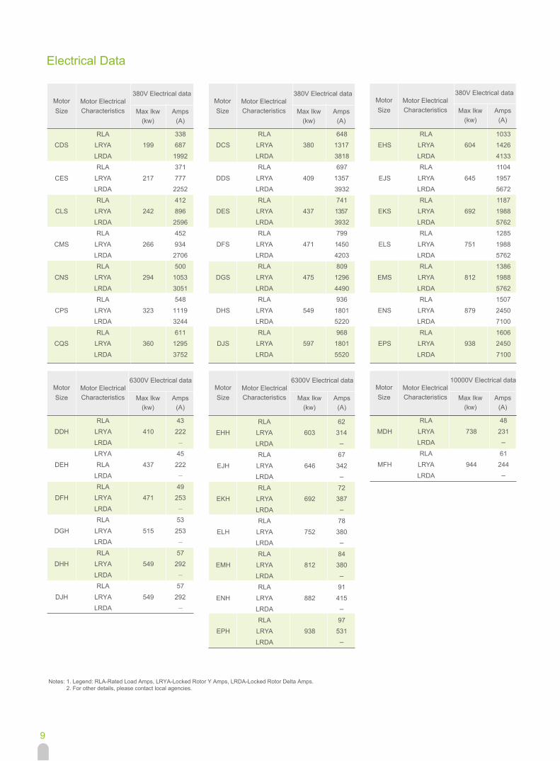
Electrical Data
Notes: 1. Legend: RLA-Rated Load Amps, LRYA-Locked Rotor Y Amps, LRDA-Locked Rotor Delta Amps. 2. For other details, please contact local agencies.
34ALRDDH LRYA 410 222
LRDALRYA 45
DEH RLA 437 222LRDA
94ALRDFH LRYA 471 253
LRDA35ALR
DGH LRYA 515 253LRDA
75ALRDHH LRYA 549 292
LRDA75ALR
DJH LRYA 549 292LRDA
RLA 1033EHS LRYA 604 1426
LRDA 4133RLA 1104
EJS LRYA 645 1957LRDA 5672
RLA 1187EKS LRYA 692 1988
LRDA 5762RLA 1285
ELS LRYA 751 1988LRDA 5762
RLA 1386EMS LRYA 812 1988
LRDA 5762RLA 1507
ENS LRYA 879 2450LRDA 7100
RLA 1606EPS LRYA 938 2450
LRDA 7100
RLA 648DCS LRYA 380 1317
LRDA 3818RLA 697
DDS LRYA 409 1357LRDA 3932
RLA 741DES LRYA 437 1357
LRDA 3932RLA 799
DFS LRYA 471 1450LRDA 4203
RLA 809DGS LRYA 475 1296
LRDA 4490RLA 936
DHS LRYA 549 1801LRDA 5220
RLA 968DJS LRYA 597 1801
LRDA 5520
RLA 338CDS LRYA 199 687
LRDA 1992RLA 371
CES LRYA 217 777LRDA 2252
RLA 412CLS LRYA 242 896
LRDA 2596RLA 452
CMS LRYA 266 934LRDA 2706
RLA 500CNS LRYA 294 1053
LRDA 3051RLA 548
CPS LRYA 323 1119LRDA 3244
RLA 611CQS LRYA 360 1295
LRDA 3752
26ALREHH LRYA 603 314
LRDA76ALR
EJH LRYA 646 342LRDA
27ALREKH LRYA 692 387
LRDA87ALR
ELH LRYA 752 380LRDA
48ALREMH LRYA 812 380
LRDA19ALR
ENH LRYA 882 415LRDA
79ALREPH LRYA 938 531
LRDA
84ALR
MDH LRYA 738 231LRDA
16ALRMFH LRYA 944 244
LRDA
MotorSize Max Ikw
(kw)Amps
(A)
Motor ElectricalCharacteristics
380V Electrical dataMotorSize Max Ikw
(kw)Amps
(A)
Motor ElectricalCharacteristics
380V Electrical data
MotorSize Max Ikw
(kw)Amps
(A)
Motor ElectricalCharacteristics
10000V Electrical dataMotorSize Max Ikw
(kw)Amps
(A)
Motor ElectricalCharacteristics
6300V Electrical dataMotorSize Max Ikw
(kw)Amps
(A)
Motor ElectricalCharacteristics
6300V Electrical data
MotorSize Max Ikw
(kw)Amps
(A)
Motor ElectricalCharacteristics
380V Electrical data
9
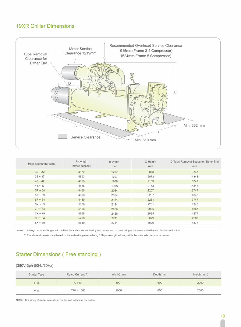
19XR Chiller Dimensions
Starter Dimensions ( Free standing )
A
B
C
Notes: 1. A-length includes flanges with both cooler and condenser having two passes and nozzles being at the same end (drive end for standard units)
2. The above dimensions are based on the waterside pressure being 1.0Mpa. A-length will vary while the waterside pressure increases.
Tube RemovalClearance for
Either End
Motor ServiceClearance 1219mm
D
Recommended Overhead Service Clearance915mm(Frame 3-4 Compressor)1524mm(Frame 5 Compressor)
Service ClearanceMin. 610 mm
Min. 362 mm
A-Lengthmm(2 passes)
B-Widthmm
C-Heightmm
D-Tube Removal Space for Either Endmm
Heat Exchanger Size
30 ~ 3235 ~ 3740 ~ 4245 ~ 475P ~ 545X ~ 596P ~ 646X ~ 697P ~ 747X ~ 798P ~ 848X ~ 89
417246934365488544604980448050005156576652005810
170717071908190820542054212421242426242627112711
207320732153215322072207226122612985298530293029
374743433747434337474343374743434267487742674877
(380V-3ph-50Hz/60Hz)
Notes: The wiring of starter enters from the top and exits from the bottom.
Starter Type
Y-
Y-
Rated Current(A)
740
740 ~ 1560
Width(mm)
800
1000
Depth(mm)
600
600
Height(mm)
2000
2000
10

C
Tube RemovalClearance for
Either End
Motor ServiceClearance 1219mm
Recommended Overhead Service Clearance1524mm(Frame E Compressor)
Service Clearance
19XR-E Chiller Dimensions
D
>762mm
>610mmA
Heat Exchanger Size
Notes: 1. A-length includes flanges with both cooler and condenser having two passes and nozzles being at the same end (drive end for standard units) 2. The above dimensions are based on the waterside pressure being 1.0Mpa. A-length will vary while the waterside pressure increases.
A-Length
mm(2 passes )
5169
5779
5205
5817
19XR-E B-Width
mm
2426
2426
2711
2711
19XR-E C-Height
mm
2902
2902
2950
2950
D-Tube Removal Space for Either End
mm
4267
4877
4267
4877
70-74/7K-7R
75-79/7T-7Z
80-84/8K-8R
85-89/8T-8Z
11
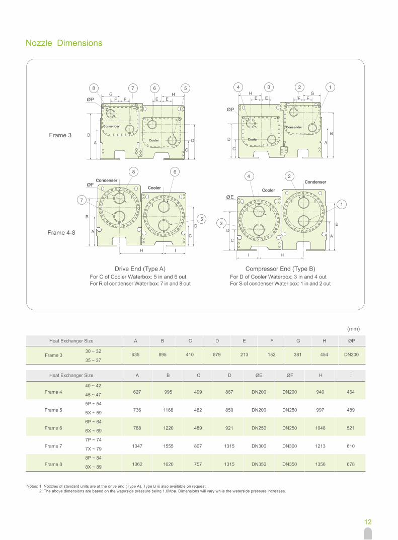
Heat Exchanger Size
30 ~ 32
35 ~ 37
B C D E F G HA
635 895 410 679 213 381 454152
ØP
DN200
(mm)
Drive End (Type A)For C of Cooler Waterbox: 5 in and 6 outFor R of condenser Water box: 7 in and 8 out
Frame 3
Frame 4-8
Nozzle Dimensions
Compressor End (Type B)For D of Cooler Waterbox: 3 in and 4 outFor S of condenser Water box: 1 in and 2 out
Frame 3
Notes: 1. Nozzles of standard units are at the drive end (Type A). Type B is also available on request. 2. The above dimensions are based on the waterside pressure being 1.0Mpa. Dimensions will vary while the waterside pressure increases.
A B C D ØE ØF H IHeat Exchanger Size
627
736
788
1047
1062
995
1168
1220
1555
1620
499
482
489
807
757
867
850
921
1315
1315
DN200
DN200
DN250
DN300
DN350
940
997
1048
1213
1356
464
489
521
610
678
DN200
DN250
DN250
DN300
DN350
40 ~ 42
45 ~ 47
5P ~ 54
5X ~ 59
6P ~ 64
6X ~ 69
7P ~ 74
7X ~ 79
8P ~ 84
8X ~ 89
Frame 4
Frame 5
Frame 6
Frame 7
Frame 8
12
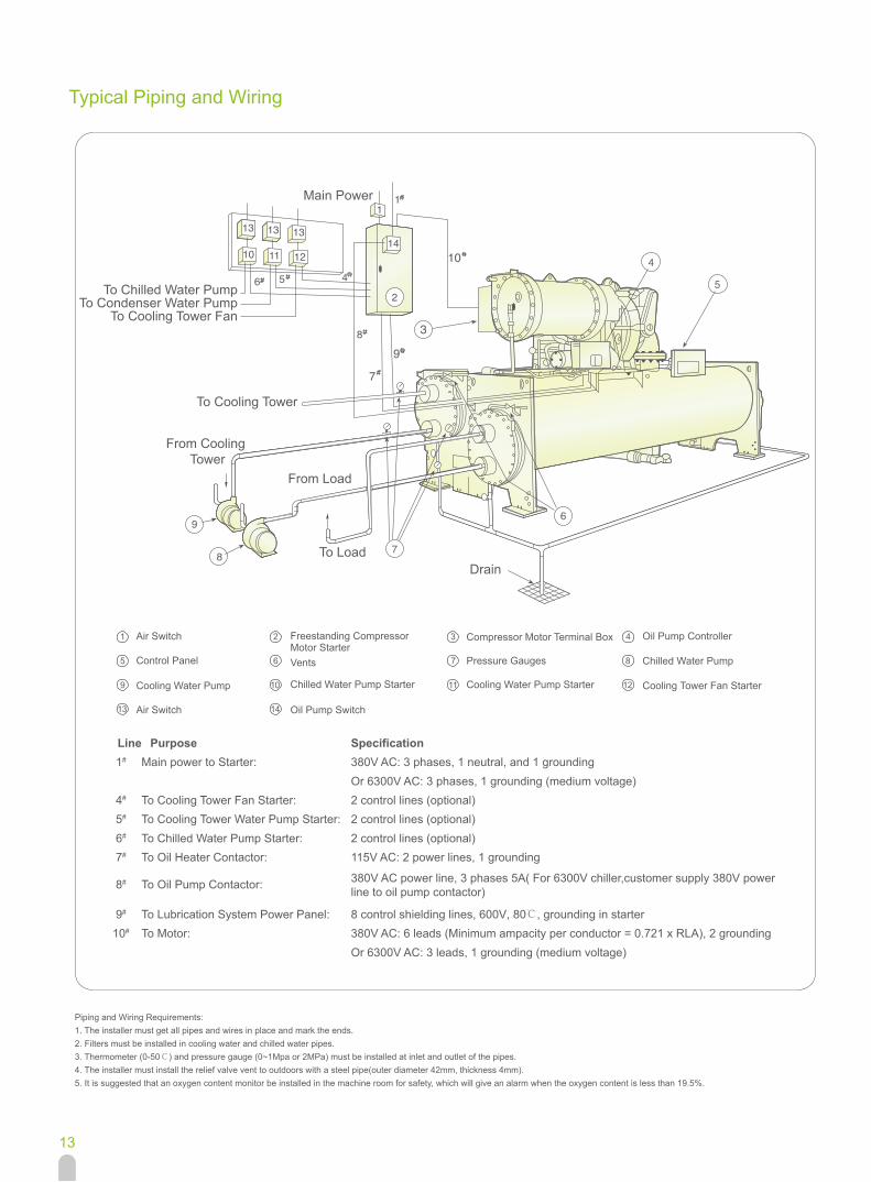
Piping and Wiring Requirements:1. The installer must get all pipes and wires in place and mark the ends.2. Filters must be installed in cooling water and chilled water pipes.3. Thermometer (0-50℃) and pressure gauge (0~1Mpa or 2MPa) must be installed at inlet and outlet of the pipes.4. The installer must install the relief valve vent to outdoors with a steel pipe(outer diameter 42mm, thickness 4mm).5. It is suggested that an oxygen content monitor be installed in the machine room for safety, which will give an alarm when the oxygen content is less than 19.5%.
Typical Piping and Wiring
DrainTo Load
From Load
To Cooling Tower
Main Power
To Chilled Water PumpTo Condenser Water Pump
To Cooling Tower Fan
From Cooling Tower
Chilled Water Pump
Specification380V AC: 3 phases, 1 neutral, and 1 groundingOr 6300V AC: 3 phases, 1 grounding (medium voltage)2 control lines (optional)2 control lines (optional)2 control lines (optional)115V AC: 2 power lines, 1 grounding
380V AC power line, 3 phases 5A( For 6300V chiller,customer supply 380V powerline to oil pump contactor)
8 control shielding lines, 600V, 80℃, grounding in starter380V AC: 6 leads (Minimum ampacity per conductor = 0.721 x RLA), 2 groundingOr 6300V AC: 3 leads, 1 grounding (medium voltage)
Air Switch
Control Panel
Oil Pump Controller
Line1#
4#
5#
6#
7#
8#
9#
10#
14
PurposeMain power to Starter:
To Cooling Tower Fan Starter:To Cooling Tower Water Pump Starter:To Chilled Water Pump Starter:To Oil Heater Contactor:
To Oil Pump Contactor:
To Lubrication System Power Panel:To Motor:
Freestanding CompressorMotor Starter
11
6
1
12
7
2
13
8
3
9
4
10
5 Vents
Cooling Water Pump Starter
Pressure Gauges
Cooling Tower Fan Starter
Compressor Motor Terminal Box
Air Switch
Cooling Water Pump
Oil Pump Switch
Chilled Water Pump Starter
13

Piping and Wiring Requirements:1. The installer must get all pipes and wires in place and mark the ends.2. Filters must be installed in cooling water and chilled water pipes.3. Thermometer (0-50˚C) and pressure gauge (0~1Mpa or 2MPa) must be installed at inlet and outlet of the pipes.4. The installer must install the relief valve vent to outdoors with a steel pipe(outer diameter 42mm, thickness 4mm).5. It is suggested that an oxygen content monitor be installed in the machine room for safety, which will give an alarm when the oxygen content is less than 19.5%.
DrainTo Load
From Load
To Cooling Tower
Main Power
To Chilled Water PumpTo Condenser Water Pump
To Cooling Tower Fan
From Cooling Tower
Typical Piping and Wiring (with VFD)
Specification
380V AC: 3 phases, 1 neutral, and 1 grounding
2 control lines (optional)
2 control lines (optional)
2 control lines (optional)
Line
1#
4#
5#
6#
Purpose
Main power to Starter:
To Cooling Tower Fan Starter:
To Cooling Tower Water Pump Starter:
To Chilled Water Pump Starter:
Cooling Water Pump
Air Switch
Vents
Oil Pump ControllerUnit-mounted Starter
6
1
7
2
8
3
9
4
10
5 Pressure Gauges Chilled Water Pump
Control Panel
Chilled Water Pump Starter Cooling Water Pump Starter
14

Types of Base Isolation
Location Of Isolator
View X-X
Support Plate
Elastomeric Pad
Jacking Screw(s)
Soleplate
Leveling Pad(s)Leveling Pad
See Note #3
Level Base Line
Jacking ScrewSee Note #2
Tube Sheet
See Note #1
THK(25)H.R.S.Soleplate
Accessory soleplate package includes 4soleplates, 16 jacking screws, and 16 levelingpads.Jacking Screws should be removed after thegrout has set.Thickness of grout varies, depending on theamount necessary to level chiller.
View Y-Y
Simplified Isolation
Tube SheetSupport Plate
Elastomeric Pad
Standard Isolation
Condenser Center
Cooler CenterAccessory Soleplate
Support Plate
1.
2.
3.
Notes:
Frame 8
Heat Exchanger Size
Frame 6
Frame 4
30~32
35~37
40~42
45~47
5P~54
5X~59
6P~64
6X~69
7P~74
7X~79
8P~84
8X~89
Frame 7
Frame 5
Frame 3
B
1632
1632
1829
1829
1969
1969
2070
2070
2400
2400
2686
2686
C
92
92
92
92
92
92
92
92
176
176
176
176
D
387
387
387
387
387
387
387
387
559
559
559
559
E
229
229
229
229
229
229
229
229
406
406
406
406
F
540
540
540
540
540
540
540
540
711
711
711
711
G
464
464
464
464
464
464
464
464
635
635
635
635
H
254
254
254
254
254
254
254
254
432
432
432
432
J
178
178
178
178
178
178
178
178
356
356
356
356
A
3931
4451
3931
4451
3931
4451
3931
4451
4620
5230
4620
5230
15
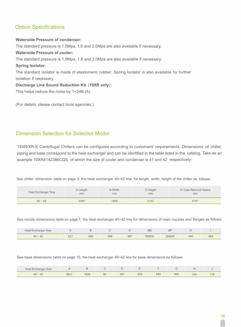
Dimension Selection for Selected Model
A
3931
C
92
D
387
F
540
G
464
H
254
J
178
Heat Exchanger Size
40 ~ 42
Heat Exchanger Size
40 ~ 42
A B C D ØE ØF H I
627 995 499 867 DN200 DN200 940 464
See chiller dimension table on page 6, the heat exchanger 40~42 line for length, width, height of the chiller as follows:
19XR/XR-E Centrifugal Chillers can be configured according to customers' requirements. Dimensions of chiller, piping and base correspond to the heat exchanger and can be identified in the table listed in the catalog. Take as an
example 19XR4142386CQS, of which the size of cooler and condenser is 41 and 42 respectively:
E
229
Waterside Pressure of condenser:The standard pressure is 1.0Mpa,
,
1.6 and 2.0Mpa are also available if necessary.Waterside Pressure of cooler:The standard pressure is 1.0Mpa 1.6 and 2.0Mpa are also available if necessary.Spring Isolator:The standard isolator is made of elastomeric rubber. Spring Isolator is also available for furtherisolation if necessary.Discharge Line Sound Reduction Kit (19XR only) :This helps reduce the noise by 1~2dB (A)
(For details, please contact local agencies.)
B
1829
Heat Exchanger SizeA-Length
mmB-Width
mmC-Height
mmD-Tube Removal Space
mm
747335128091563424 ~ 04
Option Specifications
See nozzle dimensions table on page 7, the heat exchanger 40~42 line for dimensions of main nozzles and flanges as
See base dimensions table on page 10, the heat exchanger 40~42 line for base dimensions as follows:
follows:
16

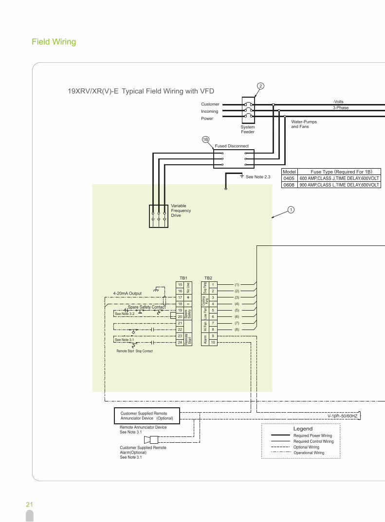
Field Wiring
19XR/XR-E Typical Field Wiring with Free-Standing Starter (380V-3ph-50Hz/60Hz)
380V-3ph-50Hz
115V-1ph-50Hz
17
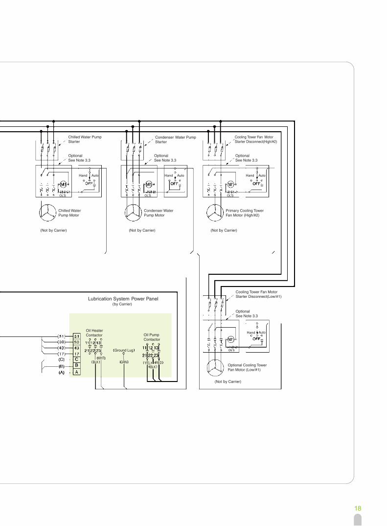
Lubrication System
18

Field Wiring
19XR/XR-E Typical Field Wiring with Free-Standing Starter (Medium Voltage)
380V-3ph-50Hz
115V-1ph-50Hz
V-1ph-50Hz
19

20
Field Wiring
Customer
Incoming
Power
SystemFeeder
Fused Disconnect
See Note 2.3
VariableFrequencyDrive
4-20mA Output
Water-Pumpsand Fans
Fuse Type (Required For 1B)Model
-Volts 3-Phase
3.2
No U
se
3.1
3.1Operational Wiring
ph
19XRV/XR(V)-E Typical Field Wiring with VFD
21

-Volts 3-Phase
3.5
22
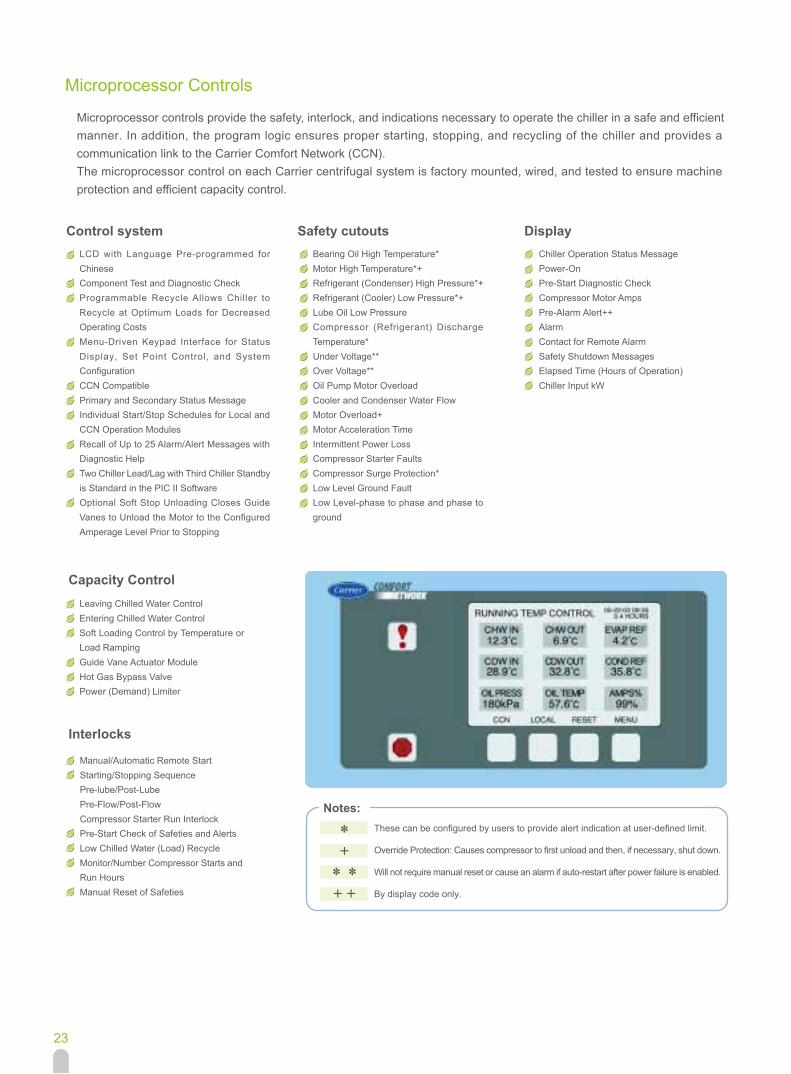
Microprocessor Controls
Microprocessor controls provide the safety, interlock, and indications necessary to operate the chiller in a safe and efficientmanner. In addition, the program logic ensures proper starting, stopping, and recycling of the chiller and provides acommunication link to the Carrier Comfort Network (CCN).The microprocessor control on each Carrier centrifugal system is factory mounted, wired, and tested to ensure machineprotection and efficient capacity control.
Notes:These can be configured by users to provide alert indication at user-defined limit.
Override Protection: Causes compressor to first unload and then, if necessary, shut down.
Will not require manual reset or cause an alarm if auto-restart after power failure is enabled.
By display code only.
Interlocks
Capacity Control
Control systemLCD with Language Pre-programmed forChineseComponent Test and Diagnostic CheckProgrammable Recycle Allows Chiller toRecycle at Optimum Loads for DecreasedOperating CostsMenu-Driven Keypad Interface for StatusDisplay, Set Point Control, and SystemConfigurationCCN CompatiblePrimary and Secondary Status MessageIndividual Start/Stop Schedules for Local andCCN Operation ModulesRecall of Up to 25 Alarm/Alert Messages withDiagnostic HelpTwo Chiller Lead/Lag with Third Chiller Standbyis Standard in the PIC II SoftwareOptional Soft Stop Unloading Closes GuideVanes to Unload the Motor to the ConfiguredAmperage Level Prior to Stopping
Leaving Chilled Water ControlEntering Chilled Water ControlSoft Loading Control by Temperature orLoad RampingGuide Vane Actuator ModuleHot Gas Bypass ValvePower (Demand) Limiter
Manual/Automatic Remote StartStarting/Stopping SequencePre-lube/Post-LubePre-Flow/Post-FlowCompressor Starter Run InterlockPre-Start Check of Safeties and AlertsLow Chilled Water (Load) RecycleMonitor/Number Compressor Starts andRun HoursManual Reset of Safeties
Safety cutoutsBearing Oil High Temperature*Motor High Temperature*+Refrigerant (Condenser) High Pressure*+Refrigerant (Cooler) Low Pressure*+Lube Oil Low PressureCompressor (Refrigerant) DischargeTemperature*Under Voltage**Over Voltage**Oil Pump Motor OverloadCooler and Condenser Water FlowMotor Overload+Motor Acceleration TimeIntermittent Power LossCompressor Starter FaultsCompressor Surge Protection*Low Level Ground FaultLow Level-phase to phase and phase toground
DisplayChiller Operation Status MessagePower-OnPre-Start Diagnostic CheckCompressor Motor AmpsPre-Alarm Alert++AlarmContact for Remote AlarmSafety Shutdown MessagesElapsed Time (Hours of Operation)Chiller Input kW
23
Field Wiring Specifications (with Free-standing Starter)
1.0
1.1
1.2
I. General
2.0
2.1
2.2
II. Power Wiring to Starter
3.0
3.1
3.2
3.3
III. Control Wiring
3.4
3.5
3.6
2.3
2.4
1.3
1.4
1.51.6
Starters shall be designed and manufactured inaccordance with Carrier Engineering Require-ment Z-415.All field-supplied conductors, devices, and thefield-installation wiring, termination of conductorsand devices, must be in compliance with allapplicable codes and job specifications.The routing of field-installed conduit andconductors and the location of field-installeddevices must not interfere with equipment accessor the reading, adjusting, or servicing of anycomponent.
Equipment installation and all starting and controldevices, must comply with details in equipmentsubmittal drawings and literature.Contacts and switches are shown in the positionthey would with the circuit deenergized and thechiller shut down.WARNING - Do not use aluminum conductors.Installer is responsible for any damage causedby improper wiring between starter and machine.
Circuit breaker is to be used to disconnect powerto starter.Unit-mounted starter power conductor ratingmust meet minimum nameplate voltage andcompressor motor RLA.Lug adapters may be required if installationconditions dictate that conductors be sizedbeyond the minimum ampacity required.
Flexible conduit should be used for the last fewfeet of the power conductor to start enclosure toprovide unit vibration isolation.Compressor motor and controls must begrounded by using equipment-grounding lugsprovided inside unit mounted starter enclosure.
Field supplied control conductors should be atleast 1 mm2 or larger.Optional ice build start/terminate device contacts,optional remote start/stop device contacts andoptional spare safety device contacts, must have24 VAC rating. MAX current is 60 MA, nominalcurrent is 10 MA. Switches with gold platedbifurcated contacts are recommended.Remove jumper wire between J2-1 and J2-2before connecting auxiliary safeties betweenthese terminals.ISM contact outputs can control cooler andcondenser pump and tower fan motor contactorcoil loads (VA) rated 5 Amps at 115 VAC up to 3Amps at 220 VAC. Do not use starter controltransformer as the power source for contactorcoil loads.
Do not route control wiring carrying 30V or lesswithin a conduit which has wires carrying 50V orhigher or along side wires carrying 50V or higher.Control wiring between free-standing starter andpower panel must be separate shielded cableswith minimum rating of 600V, 80°C Groundshield at starter.If optional oil pump circuit breaker is not suppliedwithin the starter enclosure as shown, it must belocated within sight of the chiller with wiringrouted to suit.
24

Field Wiring Specifications (with Free-standing Starter)
4.0 Low voltage (600 v or less) compressor motorshave (6) 5/8 terminal studs (lead connectorsnot supplied by Carrier). Either 3 or 6 conductorsmust be run between compressor motor andstarter, depending on the type of motor starteremployed. If only 3 leads are utilized, jumpermotor terminals as follows : 1 to 6, 2 to 4, and 3to 5. Center to center distance between terminalsis 8mm.Compressor motor starter must havenameplate stamped as to conform with CarrierEngineering Requirement Z-415.
4.1 Medium voltage [over 600 volts] compressormotors have (3) terminals. Connections are 9/16-threaded stud.Compressor motor starter musthave nameplate stamped as to conform withCarrier Engineering requirement "Z-415."
4.2 Power conductor rating must meet compressormotor RLA. When (3) conductors are used:Minimum ampacity per conductor = 1.25 xcompressor RLA When (6) conductors are used:Minimum ampacity per conductor = 0.721 xcompressor RLA
4.3 When more than one conduit is used to runconductors from starter to compressor motorterminal box, three leads from each phase(conductor) must be in each conduit to preventexcessive heating (e.g., conductors to motorterminals 1, 2, & 3 in one conduit, and those to4, 5, & 6 in another).
IV. Power Wiring Between Free-standing Starter and Compressor Motor
4.4 Compressor motor power conductors may enterterminal box through top, bottom or right sideusing holes cut by contractor to suit conduit.Flexible conduit should be used for the last fewfeet to the terminal box for unit vibrationisolation.
4.5 Compressor motor frame should be grounded inaccordance with the National Electrical Code-us(NFPA-70) and applicable codes. Means forgrounding compressor motor is a #4 AWG-500MCM pressure connector, supplied and locatedin the lower left side corner of the compressormotor terminal box.
4.6 Do not allow motor terminals to support weight ofwire cables. Use cable supports and strainrelieves as required.
4.7 Use backup wrench when tightening leadconnectors to motor terminal studs. Torque to 45lb-ft max.
4.8 Motor terminals and wire connectors must beinsulated with insulation putties and tapesattached to chil lers to prevent moisturecondensing and electrical arc.
25
Field Wiring Specifications (with VFD)
1.0 VFD starters shall be designed and manufacturedin accordance with Carrier Engineering Require-ment Z-420.
1.1 All field-supplied conductors, devices, and thefield-installation wiring, termination of conductorsand devices,must be in compliance with allapplicable codes and job specifications.
1.2 The routing of field-installed conduit andconductors and the location of field-installeddevices must not interfere with equipment accessor the reading, adjusting, or servicing of anycomponent.
I. General
2.0
2.1
2.2
II. Power Wiring to VFD Starter
3.0 Field supplied control conductors should be atleast 1 mm2 or larger.
3.1 Optional ice build start/terminate device contacts,optional remote start/stop device contacts andoptional spare safety device contacts, must have24 VAC rating. MAX current is 60 MA, nominalcurrent is 10 MA. Switches with gold platedbifurcated contacts are recommended.
3.2 Remove jumper wire between TB1-19 and TB1-20 before connecting auxiliary safeties betweenthese terminals.
III. Control Wiring
1.3 Equipment installation and all starting and controldevices, must comply with details in equipmentsubmittal drawings and literature.
1.4 Contacts and switches are shown in the positionthey would with the circuit deenergized and thechiller shut down.
1.5 WARNING - Do not use aluminum conductors.
2.3
3.3 VFD ISM contact outputs can control cooler andcondenser pump and tower fan motor contactorcoil loads (VA) rated 5 Amps at 115 VAC up to 3Amps at 227 VAC. Do not use VFD starter controltransformer as the power source for contactor coilloads.
3.4 Do not route control wiring carrying 30V or lesswithin a conduit which has wires carrying 50V orhigher or along side wires carrying 50V or higher.
3.5 VFD provide spare output terminal for customer,Input sign must be 4~20mA, not grounded. Inputresistance of terminal is soon.
Provide a means of disconnecting power tostarter. Fused disconnect is required on VFD.ncoming power wire must be protected with metaljacket.Line side power conductor rating must meet VFDnameplate voltage and chiller full load amps(minimum circuit ampacity).
Compressor motor and controls must be groundedby using equipment grounding lugs provided insideunit mounted starter enclossure.
26

The Manufacturer reserves the right to change any produt specifications without prior notices Version:
Supersede:
CAT_19XR/XR-E_E-1304_02
CAT_19XR_E-1205_01
Apr, 2013Effective Date: