HENKE ALL-HYDRAULIC WINGhenkemfg.com/.../AHW_CASE_845TO885_NH...8510301_02.pdf · For Case 845-885...
88
AHW_CASE_845TO885_NH_RG140TORG200_EFF_JAN2013_TO_PRES_8510301_02_033.DOCX HENKE ALL-HYDRAULIC WING Models: AHW 42BH, AHW 66BH For Case 845-885 & New Holland RG140-RG200 Series Graders PARTS BOOK AND INSTALLATION MANUAL Serial Number: _______________ VERSION 3.3, APRIL 2015 HENKE MANUFACTURING CORPORATION MANUFACTURERS OF SNOW REMOVAL EQUIPMENT FOR 95 YEARS 3070 WILSON AVE. LEAVENWORTH, KS 66048 PHONE (913)682-9000 FAX(913)682-0300 WEBSITE ADDRESS : WWW.HENKEMFG.COM EMAIL: [email protected]
Transcript of HENKE ALL-HYDRAULIC WINGhenkemfg.com/.../AHW_CASE_845TO885_NH...8510301_02.pdf · For Case 845-885...

AHW_CASE_845TO885_NH_RG140TORG200_EFF_JAN2013_TO_PRES_8510301_02_033.DOCX
HENKE ALL-HYDRAULIC WING Models: AHW 42BH, AHW 66BH For Case 845-885 & New Holland RG140-RG200 Series Graders
PARTS BOOK AND INSTALLATION MANUAL Serial Number: _______________ VERSION 3.3, APRIL 2015
HENKE MANUFACTURING CORPORATION MANUFACTURERS OF SNOW REMOVAL EQUIPMENT FOR 95 YEARS 3070 WILSON AVE. LEAVENWORTH, KS 66048 PHONE (913)682-9000 FAX(913)682-0300 WEBSITE ADDRESS : WWW.HENKEMFG.COM EMAIL: [email protected]

AHW_CASE_845TO885_NH_RG140TORG200_EFF_JAN2013_TO_PRES_8510301_02_033.DOCXPage 2 of 67
<THIS PAGE IS INTENTIONALLY LEFT BLANK>
AHW_CASE_845TO885_NH_RG140TORG200_EFF_JAN2013_TO_PRES_8510301_02_033.DOCXPage 3 of 67
Introduction
Thank you for your purchase of a Henke All Hydraulic Wing for your Case or New Holland motor grader. The bolt-up/bolt-up attaching structure design of this wing allows greater rotation of the main grader blade than other designs, which improves snow moving capability. The All Hydraulic Wing consists of four main subassemblies: 1. Wing Post and Attachment Assemblies
2. Moldboard and Pushbeam Assemblies
3. Rear Attachment Assembly (either: Elevating Rear, Fixed Rear,
Manually Elevating Rear, or Rear Ripper Attachment)
4. Hydraulic Hoses and Fittings Before beginning your installation, please check that all of the appropriate ship-loose parts and hardware listed in Table 1 was received. In the unlikely event that any parts are missing, please contact Henke Manufacturing Corporation for replacements. The cutting path, defined as the distance perpendicular to the motion of the vehicle, of the snow wing is approximately 80% of the moldboard length. Therefore, an AHW-12’ would have a cutting path of almost 10 feet. The parts lists for the AHW Case/NH snow wing are listed in Tables 2 thru 12 (if applicable). These lists are important and should be referred to when ordering replacement parts from your local dealer or Henke Manufacturing Corporation. The parts diagrams for the snow wing are shown in Figures 1 thru 7. This Product Manual should be read in its entirety before using your Henke AHW Case/NH snow wing to minimize mounting problems. For customer service, replacement parts, or answers to questions about your Henke plow, please call Henke Manufacturing at (913) 682-9000.

AHW_CASE_845TO885_NH_RG140TORG200_EFF_JAN2013_TO_PRES_8510301_02_033.DOCXPage 4 of 67
Table of Contents
Introduction ..................................................................................................................... 3
Wing Installation Loose Hardware ................................................................................. 10
Parts Figures and Parts Lists ........................................................................................ 11
Mounting Instructions .................................................................................................... 53
Henke Warranty ............................................................................................................ 66
Dealer Warranty Procedure ........................................................................................... 67
List of Tables
Table 1 – Wing Installation Loose Hardware ................................................................. 10
Table 2 - Front Post Assembly and Attachments, Parts List ......................................... 12
Table 3 - AHW Moldboard Assembly & Attachments, Parts List ................................... 14
Table 4 - Elevating Rear Assembly, Parts List .............................................................. 16
Table 5 - Rear Ripper Assembly, Parts List .................................................................. 17
Table 6 - Fixed Rear Assembly, Parts List .................................................................... 18
Table 7 - 2-Section Valve & Controls Kit 6182602 ........................................................ 25
Table 8 - 3-Section Valve & Controls Kit 6182603 ........................................................ 26
Table 9 - Special 3-Section Valve & Controls Kit 6182604 ............................................ 27
Table 10 - Hydraulic Tie-In Kit 7080465 ........................................................................ 28
Table 11 - Cylinder Hose Kit 7080464........................................................................... 29
Table 12 - Elevating Rear Hose Kit 7080466 ................................................................ 30
Table 13 - DRY Torque Values for Toplock (All-Metal) or Nylock Nuts Only ................. 62
Table 13 - DRY Torque Values for Standard Non-Locking Nuts ONLY ........................ 62
Table 14 - Henke Cutting Edges ................................................................................... 63
Table 15 - Henke Cutting Edge Hardware ..................................................................... 64
Table 16 - Henke Curb Guards and Wear Guards ........................................................ 65

AHW_CASE_845TO885_NH_RG140TORG200_EFF_JAN2013_TO_PRES_8510301_02_033.DOCXPage 5 of 67
List of Figures Figure 1. Henke All Hydraulic Wing on CASE Grader .......................................... COVER
Figure 2. Front Post Assembly & Attachments ............................................................. 11
Figure 3. AHW Moldboard Assembly & Attachments ................................................... 13
Figure 4. AHW Elevating Rear Assembly .................................................................... 15
Figure 5. Rear Ripper Assembly .................................................................................. 17
Figure 6. Fixed Rear Assembly .................................................................................... 18
Figure 7. Welded-On Mounting Plate Installation ......................................................... 19
Figure 8. Hydraulic Hoses and Fittings Running From Henke Valve ............................ 20
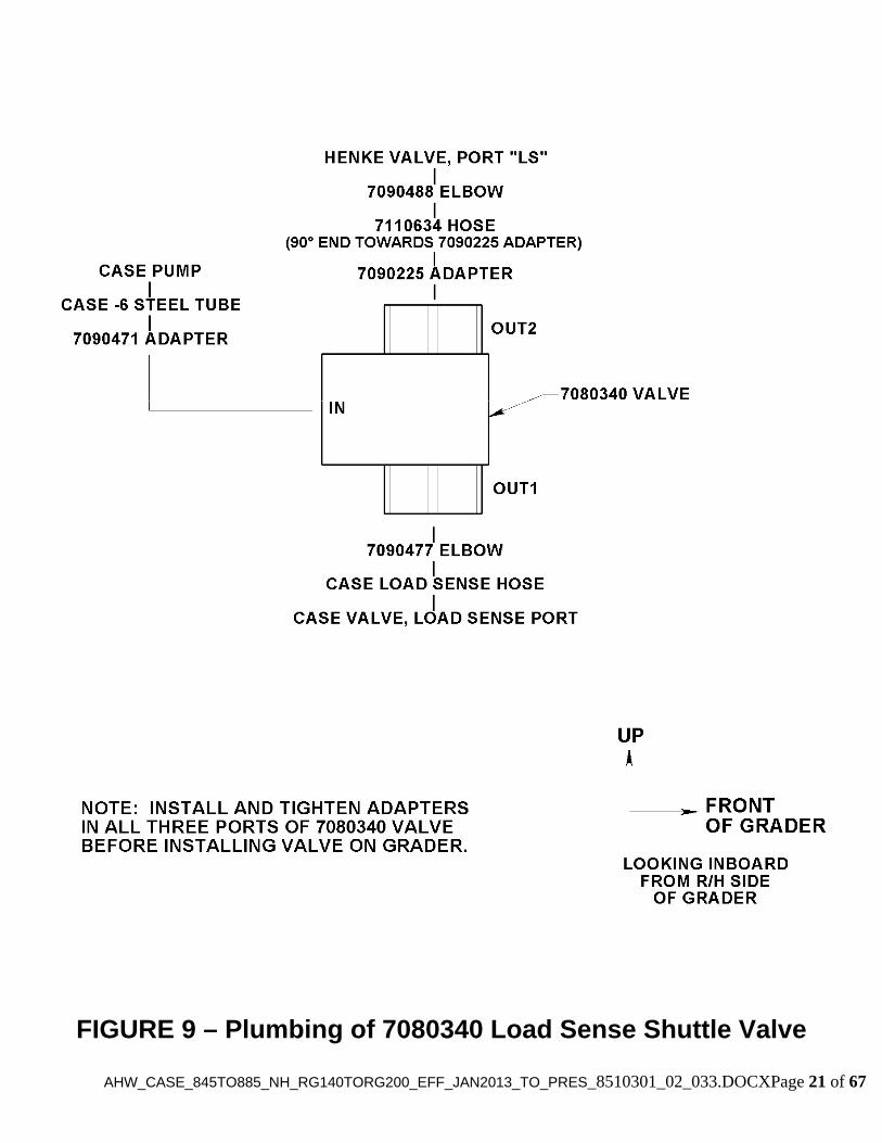
Figure 9. Plumbing of 7080340 Load Sense Shuttle Valve .......................................... 21
Figure 10. Hydraulic Schematic from Bulkhead Plate to Wing ..................................... 22
Figure 11. Mounting of Henke MUDROC Valve on Wing Post ..................................... 23
Figure 12. REQUIRED ADJUSTMENT! - MUDROC Relief Valve Adjustment ............. 24
Figure 101. Installation of Post Attaching Structure on Grader .................................... 31
Figure 102. Front Pipe Brace Ear Mounting ................................................................. 32
Figure 103. Rear Pipe Brace Ear Mounting .................................................................. 33
Figure 104. Front Pipe Brace Mounting ........................................................................ 34
Figure 105. Rear Pipe Brace Mounting ........................................................................ 35
Figure 106. Elevating Rear Assembly (View 1 of 2) ..................................................... 36
Figure 107. Elevating Rear Assembly (View 2 of 2) ..................................................... 37
Figure 108. Fixed Rear Assembly ................................................................................ 38
Figure 109. Rear Ripper Attachment ............................................................................ 39
Figure 110. Henke Control Valve Mounting .................................................................. 40
Figure 111. Henke Control Valve Mounting & Load Sense Hose Attachment .............. 41
Figure 112. Drilling of Hole in Cab Floor ...................................................................... 42
Figure 113. Installation of Control Handles & Cables ................................................... 43
Figure 114. Installation of Load Sense Shuttle Valve (View 1 of 2) .............................. 44
Figure 115. Installation of Load Sense Shuttle Valve (View 2 of 2) .............................. 45
Figure 116. Henke Pressure Hose Attachment to Case System .................................. 46
Figure 117. Case Hard Line Replace with Customized Hard Line ............................... 47
Figure 118. Attachment of Henke Return Hose to Case Tank ..................................... 48
Figure 119. Henke Bulkhead Plate, Unbolted .............................................................. 59
Figure 120. Henke Bulkhead Plate, Installed. .............................................................. 50
Figure 121. Looping of Hoses on Rear of Wing Post ................................................... 51
Figure 122. Attachment of Hoses to Clamp on Wing Slide Assembly .......................... 52

AHW_CASE_845TO885_NH_RG140TORG200_EFF_JAN2013_TO_PRES_8510301_02_033.DOCXPage 6 of 67
<THIS PAGE IS INTENTIONALLY LEFT BLANK>

Safety Section 1-1
© 2009 Alamo Group Inc.
SAFETY SECTION
SAFETY
Wings and High Gate Safety Section 1-2
© 2009 Alamo Group Inc.
SA
FE
TY
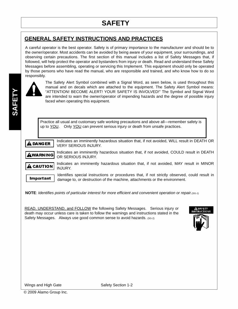
GENERAL SAFETY INSTRUCTIONS AND PRACTICES
A careful operator is the best operator. Safety is of primary importance to the manufacturer and should be tothe owner/operator. Most accidents can be avoided by being aware of your equipment, your surroundings, andobserving certain precautions. The first section of this manual includes a list of Safety Messages that, iffollowed, will help protect the operator and bystanders from injury or death. Read and understand these SafetyMessages before assembling, operating or servicing this Implement. This equipment should only be operatedby those persons who have read the manual, who are responsible and trained, and who know how to do soresponsibly.
The Safety Alert Symbol combined with a Signal Word, as seen below, is used throughout thismanual and on decals which are attached to the equipment. The Safety Alert Symbol means:“ATTENTION! BECOME ALERT! YOUR SAFETY IS INVOLVED!” The Symbol and Signal Wordare intended to warn the owner/operator of impending hazards and the degree of possible injuryfaced when operating this equipment.
Indicates an imminently hazardous situation that, if not avoided, WILL result in DEATH ORVERY SERIOUS INJURY.
Indicates an imminently hazardous situation that, if not avoided, COULD result in DEATHOR SERIOUS INJURY.
Indicates an imminently hazardous situation that, if not avoided, MAY result in MINORINJURY.
Identifies special instructions or procedures that, if not strictly observed, could result indamage to, or destruction of the machine, attachments or the environment.
NOTE: Identifies points of particular interest for more efficient and convenient operation or repair.(SG-1)
Practice all usual and customary safe working precautions and above all---remember safety isup to YOU. Only YOU can prevent serious injury or death from unsafe practices.
READ, UNDERSTAND, and FOLLOW the following Safety Messages. Serious injury ordeath may occur unless care is taken to follow the warnings and instructions stated in theSafety Messages. Always use good common sense to avoid hazards. (SG-2)
SAFETY
Wings and High Gate Safety Section 1-3
© 2009 Alamo Group Inc.
SA
FE
TY
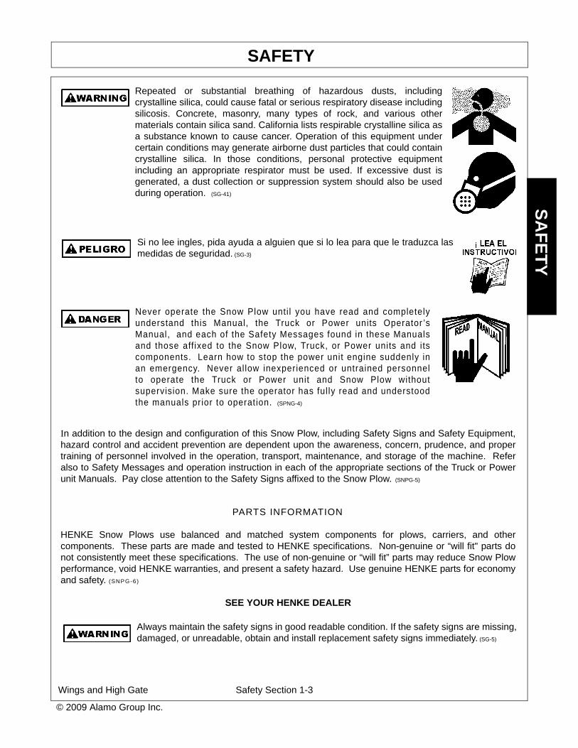
Repeated or substantial breathing of hazardous dusts, includingcrystalline silica, could cause fatal or serious respiratory disease includingsilicosis. Concrete, masonry, many types of rock, and various othermaterials contain silica sand. California lists respirable crystalline silica asa substance known to cause cancer. Operation of this equipment undercertain conditions may generate airborne dust particles that could containcrystalline silica. In those conditions, personal protective equipmentincluding an appropriate respirator must be used. If excessive dust isgenerated, a dust collection or suppression system should also be usedduring operation. (SG-41)
Si no lee ingles, pida ayuda a alguien que si lo lea para que le traduzca lasmedidas de seguridad. (SG-3)
Never operate the Snow Plow unti l you have read and completelyunderstand this Manual, the Truck or Power units Operator ’sManual, and each of the Safety Messages found in these Manualsand those aff ixed to the Snow Plow, Truck, or Power units and itscomponents. Learn how to stop the power unit engine suddenly inan emergency. Never al low inexperienced or untrained personnelto operate the Truck or Power unit and Snow Plow withoutsupervision. Make sure the operator has ful ly read and understoodthe manuals prior to operation. (SPNG-4)
In addition to the design and configuration of this Snow Plow, including Safety Signs and Safety Equipment,hazard control and accident prevention are dependent upon the awareness, concern, prudence, and propertraining of personnel involved in the operation, transport, maintenance, and storage of the machine. Referalso to Safety Messages and operation instruction in each of the appropriate sections of the Truck or Powerunit Manuals. Pay close attention to the Safety Signs affixed to the Snow Plow. (SNPG-5)
PARTS INFORMATION
HENKE Snow Plows use balanced and matched system components for plows, carriers, and othercomponents. These parts are made and tested to HENKE specifications. Non-genuine or “will fit" parts donot consistently meet these specifications. The use of non-genuine or “will fit” parts may reduce Snow Plowperformance, void HENKE warranties, and present a safety hazard. Use genuine HENKE parts for economyand safety. (SNPG-6)
SEE YOUR HENKE DEALER
Always maintain the safety signs in good readable condition. If the safety signs are missing,damaged, or unreadable, obtain and install replacement safety signs immediately. (SG-5)

SAFETY
Wings and High Gate Safety Section 1-4
© 2009 Alamo Group Inc.
SA
FE
TY
OPERATOR SAFETY INSTRUCTIONS AND PRACTICES
All Safety Shields, Guards and other Protective Safety devices should be used andmaintained in good working condit ion. All safety devices should be inspectedcareful ly at least daily for missing or broken components. NEVER REMOVEPROTECTIVE SHIELDS AND GUARDS! NEVER MODIFY OR CUT PROTECTIVE SHIELDS ORGUARDS! When shields or guards are removed to access areas for maintenance, they must bereplaced and be in good condition before operating. Missing, broken, or worn shields,guards, and other protective devices must be replaced at once and prior to operationto reduce the possibil i ty of injury. (SNPS-02)
The Snow Plow power unit should be equipped with a fire extinguisher, rated for all fires, inan accessible and visible area. The fire extinguisher should be inspected routinely by acertified inspector for operational use and replaced as needed. Never obstruct access tothe fire extinguisher. (SNPS-6)
NEVER use drugs or alcohol immediately before or while driving or operating the SnowPlow. Drugs and alcohol will affect an operator’s alertness and coordination and thereforeaffect the operator’s ability to operate the Equipment safely. Before operating theEquipment, an operator on prescription or over-the-counter medication mustconsult a medical professional regarding any side effects of the medicationthat would hinder their ability to operate the Equipment safely. NEVERknowingly allow anyone to operate this Equipment when their alertness orcoordination is impaired. Serious injury or death to the operator or otherscould result if the operator is under the influence of drugs or alcohol. (SNPD-3)
Always wear OSHA approved Personal Protective Equipment (PPE) while operating,servicing, repairing, and/or cleaning the Equipment. PPE is designed to provide bodilyprotection during such activities.
Personal Protective Equipment includes:-Protective Eye Wear-Steel Toed Safety Footwear-Gloves-Hearing Protection-Close Fitted Clothing-Hard Hat-When working around a raised hopper.-Respirator-Depending on conditions and material being swept or cleaned.
Specialized protective equipment may be required if dangerous or hazardous material is being moved by theplow. (SNPD-4)
SAFETY
Wings and High Gate Safety Section 1-5
© 2009 Alamo Group Inc.
SA
FE
TY
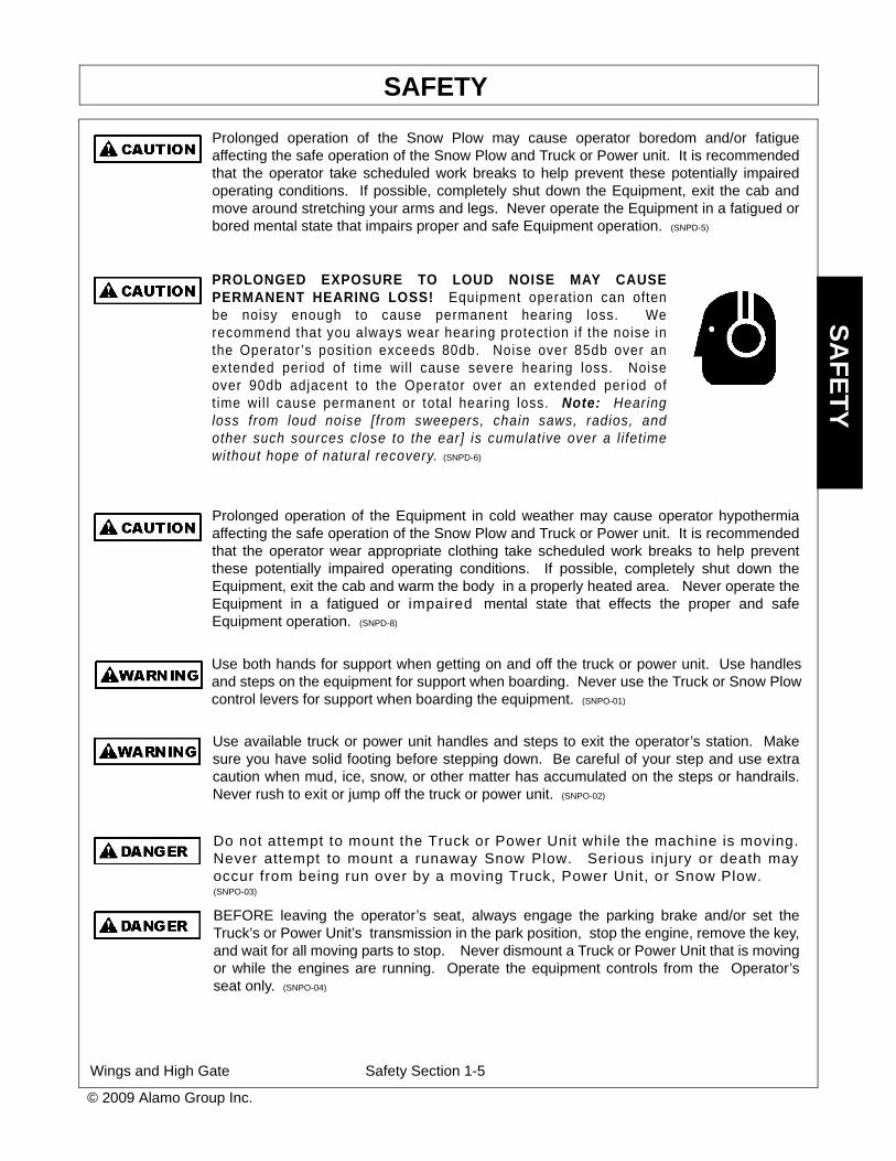
Prolonged operation of the Snow Plow may cause operator boredom and/or fatigueaffecting the safe operation of the Snow Plow and Truck or Power unit. It is recommendedthat the operator take scheduled work breaks to help prevent these potentially impairedoperating conditions. If possible, completely shut down the Equipment, exit the cab andmove around stretching your arms and legs. Never operate the Equipment in a fatigued orbored mental state that impairs proper and safe Equipment operation. (SNPD-5)
PROLONGED EXPOSURE TO LOUD NOISE MAY CAUSEPERMANENT HEARING LOSS! Equipment operation can oftenbe noisy enough to cause permanent hearing loss. Werecommend that you always wear hearing protection if the noise inthe Operator ’s posit ion exceeds 80db. Noise over 85db over anextended period of t ime will cause severe hearing loss. Noiseover 90db adjacent to the Operator over an extended period oft ime wil l cause permanent or total hearing loss. Note: Hearingloss from loud noise [from sweepers, chain saws, radios, andother such sources close to the ear] is cumulative over a l ifetimewithout hope of natural recovery. (SNPD-6)
Prolonged operation of the Equipment in cold weather may cause operator hypothermiaaffecting the safe operation of the Snow Plow and Truck or Power unit. It is recommendedthat the operator wear appropriate clothing take scheduled work breaks to help preventthese potentially impaired operating conditions. If possible, completely shut down theEquipment, exit the cab and warm the body in a properly heated area. Never operate theEquipment in a fatigued or impaired mental state that effects the proper and safeEquipment operation. (SNPD-8)
Use both hands for support when getting on and off the truck or power unit. Use handlesand steps on the equipment for support when boarding. Never use the Truck or Snow Plowcontrol levers for support when boarding the equipment. (SNPO-01)
Use available truck or power unit handles and steps to exit the operator’s station. Makesure you have solid footing before stepping down. Be careful of your step and use extracaution when mud, ice, snow, or other matter has accumulated on the steps or handrails.Never rush to exit or jump off the truck or power unit. (SNPO-02)
Do not attempt to mount the Truck or Power Unit while the machine is moving.Never attempt to mount a runaway Snow Plow. Serious injury or death mayoccur from being run over by a moving Truck, Power Unit, or Snow Plow.(SNPO-03)
BEFORE leaving the operator’s seat, always engage the parking brake and/or set theTruck’s or Power Unit’s transmission in the park position, stop the engine, remove the key,and wait for all moving parts to stop. Never dismount a Truck or Power Unit that is movingor while the engines are running. Operate the equipment controls from the Operator’sseat only. (SNPO-04)
SAFETY
Wings and High Gate Safety Section 1-6
© 2009 Alamo Group Inc.
SA
FE
TY
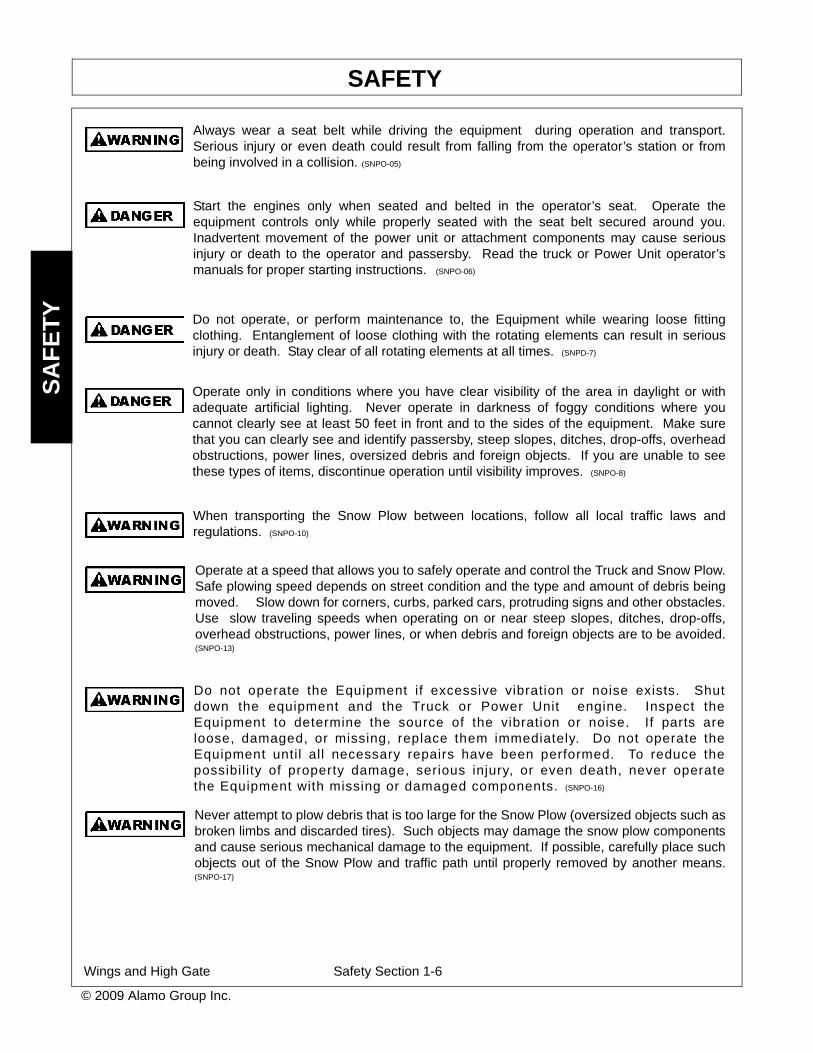
Always wear a seat belt while driving the equipment during operation and transport.Serious injury or even death could result from falling from the operator’s station or frombeing involved in a collision. (SNPO-05)
Start the engines only when seated and belted in the operator’s seat. Operate theequipment controls only while properly seated with the seat belt secured around you.Inadvertent movement of the power unit or attachment components may cause seriousinjury or death to the operator and passersby. Read the truck or Power Unit operator’smanuals for proper starting instructions. (SNPO-06)
Do not operate, or perform maintenance to, the Equipment while wearing loose fittingclothing. Entanglement of loose clothing with the rotating elements can result in seriousinjury or death. Stay clear of all rotating elements at all times. (SNPD-7)
Operate only in conditions where you have clear visibility of the area in daylight or withadequate artificial lighting. Never operate in darkness of foggy conditions where youcannot clearly see at least 50 feet in front and to the sides of the equipment. Make surethat you can clearly see and identify passersby, steep slopes, ditches, drop-offs, overheadobstructions, power lines, oversized debris and foreign objects. If you are unable to seethese types of items, discontinue operation until visibility improves. (SNPO-8)
When transporting the Snow Plow between locations, follow all local traffic laws andregulations. (SNPO-10)
Operate at a speed that allows you to safely operate and control the Truck and Snow Plow.Safe plowing speed depends on street condition and the type and amount of debris beingmoved. Slow down for corners, curbs, parked cars, protruding signs and other obstacles.Use slow traveling speeds when operating on or near steep slopes, ditches, drop-offs,overhead obstructions, power lines, or when debris and foreign objects are to be avoided.(SNPO-13)
Do not operate the Equipment if excessive vibration or noise exists. Shutdown the equipment and the Truck or Power Unit engine. Inspect theEquipment to determine the source of the vibration or noise. If parts areloose, damaged, or missing, replace them immediately. Do not operate theEquipment until all necessary repairs have been performed. To reduce thepossibil ity of property damage, serious injury, or even death, never operatethe Equipment with missing or damaged components. (SNPO-16)
Never attempt to plow debris that is too large for the Snow Plow (oversized objects such asbroken limbs and discarded tires). Such objects may damage the snow plow componentsand cause serious mechanical damage to the equipment. If possible, carefully place suchobjects out of the Snow Plow and traffic path until properly removed by another means.(SNPO-17)

SAFETY
Wings and High Gate Safety Section 1-7
© 2009 Alamo Group Inc.
SA
FE
TY
Unplowed snow, piled ice and debris, and snow drifts left behind the equipment might posea driving hazard to vehicle traffic colliding with the debris or losing traction on the material.It is recommended to post warning signs alerting driver’s of the equipment operationpresence and the need to reduce vehicle speed. If such hazards are left behind followingthe Snow Plows passage, the area should be plowed a second time and any remaininghazards removed by an alternative method. (SNPO-19)
Use extreme caution when lowering the Snow Wing. Make sure no bystanders are closeby or underneath the wing while lowering. Allow ample clearance around the equipmentwhen lowering or raising the wing. Use extreme caution around obstructions includingbystanders, passersby, curbs, buildings, and other property. Use the Truck’s or PowerUnit’s horn to warn of danger when the wing is being lowered. Lower wing slowly andcarefully. Sudden or unexpected dropping of wing could result in serious injury. (SNPO-24)
Do not allow the Snow Plow to come in contact with potentially dangerous and/orhazardous material. Such hazards may include, but are not exclusively limited to, thefollowing:
• Fire Hazards- Fuel spills, burning material,• Chemical Hazards- Chemical spills, discarded chemical containers, batteries, • Biological Hazards- Decaying Carcasses, BioMedical Waste,• Radioactive Hazards-Radioactive Waste, Radioactive Material,• Carcinogenic Materials-Asbestos,• Corrosive Materials-Batteries, Acids and Bases.
In most areas, these types of material require special handling requirements for safe and proper disposal andshould not be plowed by the Snow Plow, nor can they be disposed of in a general landfill site like most sweptwaste. Contact the appropriate authority for the collection and disposal requirements of such dangerous and/or hazardous material. (SNPO-25)
Always wear required OSHA approved Personal Protective Equipment (PPE) when comingin contact with and removing potentially dangerous and hazardous material that hascollected on the Snow Plow equipment or which is obstructing one or more components.Pay close attention to dangerous and hazardous material including, but not exclusivelylimited to, chemicals, decaying carcasses and sharp objects. (SNPO-26)
Verbal communication near a Truck or Power Unit and Snow Plow is difficult anddangerous. Operating instructions and directions should be made prior to starting theequipment. Unclear and misunderstood communication may lead to operator andbystander injury or death and equipment damage. If communication by the operator isnecessary, completely shutdown and exit the equipment. Never allow anyone to approachthe equipment while in operation. (SNPO-28)
Never allow children to play on, under, or around the Truck or Power Unit nor allow childrento operate equipment controls. Children can slip or fall off the equipment and be injured orkilled. Children can cause the equipment components to shift or fall crushing themselvesor others. (SNPO-29)
SAFETY
Wings and High Gate Safety Section 1-8
© 2009 Alamo Group Inc.
SA
FE
TY
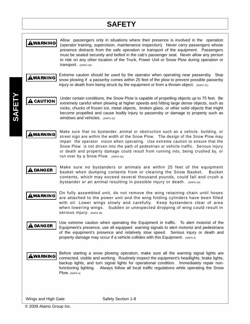
Allow passengers only in situations where their presence is involved in the operation(operator training, supervision, maintenance inspection). Never carry passengers whosepresence distracts from the safe operation or transport of the equipment. Passengersmust be seated securely and belted in the cab’s passenger seat. Never allow any personto ride on any other location of the Truck, Power Unit or Snow Plow during operation ortransport. (SNPO-30)
Extreme caution should be used by the operator when operating near passersby. Stopsnow plowing if a passerby comes within 25 feet of the plow to prevent possible passerbyinjury or death from being struck by the equipment or from a thrown object. (SNPO-31)
Under certain conditions, the Snow Plow is capable of propelling objects up to 75 feet. Beextremely careful when plowing at higher speeds and hitting large dense objects, such asrocks, chucks of frozen ice, metal objects, broken glass, or other solid objects that mightbecome propelled and cause bodily injury to passersby or damage to property such aswindows and vehicles. (SNPO-32)
Make sure that no bystander, animal or obstruction such as a vehicle, building, orstreet sign are within the width of the Snow Plow. The design of the Snow Plow mayimpair the operator vision when operating. Use extreme caution to ensure that theSnow Plow is not driven into the path of pedestrian or vehicle traff ic. Serious injuryor death and property damage could result from running into, being crushed by, orrun over by a Snow Plow. (SNPO-33)
Make sure no bystanders or animals are within 25 feet of the equipmentbasket when dumping contents from or cleaning the Snow Basket. Bucketcontents, which may exceed several thousand pounds, could fall and crush abystander or an animal resulting in possible injury or death. (SNPO-34)
On fully assembled unit, do not remove the wing retaining chain until hosesare attached to the power unit and the wing folding cylinders have been fil ledwith oil. Lower wings slowly and carefully. Keep bystanders clear of areawhen lowering wings. Sudden or unexpected dropping of wing could result inserious injury. (SNPO-36)
Use extreme caution when operating the Equipment in traffic. To alert motorist of theEquipment’s presence, use all equipped warning signals to alert motorist and pedestriansof the equipment’s presence and relatively slow speed. Serious injury or death andproperty damage may occur if a vehicle collides with this Equipment. (SNPS-3)
Before starting a snow plowing operation, make sure all the warning signal lights areconnected, visible and working. Routinely inspect the equipment’s headlights, brake lights,backup lights, and turn signal lights for operational condition. Immediately repair non-functioning lighting. Always follow all local traffic regulations while operating the SnowPlow. (SNPS-4)

SAFETY
Wings and High Gate Safety Section 1-9
© 2009 Alamo Group Inc.
SA
FE
TY
CONNECTING OR DISCONNECTING IMPLEMENT SAFETY INSTRUCTIONS AND PRACTICES
Always turn on all safety lights and flashers when you operate the Snow Plow. (SNPS-5)
Be particularly careful in transport. The Implement has raised and moved the center ofgravity to the front of the Power Unit increasing the possibility of overturn and tippingforward. Turn curves or go up slopes only at low speed and using a gradual turning angle.Go up slopes with the Implement located uphill. Slow down on rough or uneven surfaces.(SPU-2)
Do not stand or allow bystander or coworkers between the attachmentand the truck or power unit while installing or disconnecting theattachment. Keep hands and body clear of the attachment and theattachment mounts. Serious injury or death can result from a personbeing crushed between the attachment and truck or power unit. (SNPC-01)
Reset the tripped snow plow edge by raising the snow plow off the ground. DO NOTattempt to reset the trip edge by hand. The trip edge is spring loaded and sudden andunexpected movement can occur resulting in serious injuries. Keep and hands and feetaway from the trip edge. If the trip edge does not reset, stop plowing and have the snowplow repaired before resuming snow plowing. (SNPO-12)
Make sure the implement is properly attached to the Power Unit and the retaining pinssecurely lock the Implement into position. Improper mounting of the Implement onto thePower Unit can result in the Implement falling causing serious injury. (SNPC-02)
The operator of the equipment must be trained in the operation and safe use of thismachine. The operator must read and completely understand the operator’s manuals ofthe Snow Plow, Truck or Power unit manufacturers. New operators should be trained in anopen area clear of obstructions before operating on public roadways. If operation of theentire Snow Plow unit (Truck or Power unit) is not completely understood, consult yourauthorized sales representative for a detailed explanation. Never allow an untrained orunqualified driver to operate the Snow Plow. (SNPD-1)
The Snow Plow driver must meet the requirements and possess a Motor Vehicle Licenseas determined by the state in which the Snow Plow is operated if used on public roadways.Contact your local State Department of Public Safety office for special licensingrequirements to operate the Snow Plow in your area. (SNPD-2)

SAFETY
Wings and High Gate Safety Section 1-10
© 2009 Alamo Group Inc.
SA
FE
TY
MAINTENANCE AND SERVICE SAFETY INSTRUCTIONS AND PRACTICES
Perform service, repairs and lubrication according to the maintenance section. Ensure theunit is properly lubricated as specified in the lubrication schedule and all bolts and nuts areproperly torqued. Failure to properly service, repair and maintain this Implement in goodoperating condition could cause component failure and possible serious injury or evendeath. (SG-35)
Periodically inspect all moving parts for wear and replacewhen necessary with authorized service parts. Look for loosefasteners, worn or broken parts, and leaky or loose fitt ings.Make sure all pins are properly secured. Serious injury mayoccur from not maintaining this equipment in good workingorder. (SNPM-01)
Inspect the entire Snow Plow before each use. Accidents may occur or damage to theequipment may result if the Snow Plow is not maintained in good mechanical workingorder.
• Check for loose bolts, worn or broken parts, pinched hydraulic hoses, and leaky or loose fittings.• Make sure all pins are secure and safety pin equipped.• Make sure replacement parts are the correct size and properly installed.• Make sure all fluid levels are full and replenish as necessary.• Make sure fuel, oil, and coolant caps are replaced and tightened.• Check tire condition for tread wear and tire pressure at the rated PSI.• Make sure that all safety shields and guards are attached and in good condition.• Make sure all scheduled maintenance is up to date. (SNPM-02)
Do not modify or alter this Snow Plow. Do not permit anyone to modify oralter this equipment, any of its components or any Snow Plow function.Modification can result in equipment failure and cause serious injuries to theoperator, coworkers, or bystanders. (SNPM-03)
Use extreme care when climbing onto the equipment to perform repairs, maintenance,and cleaning. Use proper stands and ladders to access areas that cannot be reached fromground level. Slipping and falling off the equipment can cause serious injury or death.(SNPM-04)
Never attempt to repair, lubricate, adjust, clean, remove obstructions or perform any othertype of service to any component while the Snow Plow is in motion or while the engine isrunning. Completely shut down the engine and wait for all motion to come to a completestop before servicing the Snow Plow. (SNPM-05)

SAFETY
Wings and High Gate Safety Section 1-11
© 2009 Alamo Group Inc.
SA
FE
TY
Never leave the Snow Plow unattended while the plow is in the raised position. Accidentaloperation of the lifting lever or a hydraulic failure may cause a sudden drop of the unitwhich could result in injury or death by crushing. If the plow must be raised for inspectionor service securely block up and support the Plow to prevent it falling. (SNPM-06)
Never crawl under the Snow Plow or any raised component unless it is properly blockedup and support to prevent it from falling. Accidental operation of a lifting lever or hydraulicfailure may cause a sudden drop of the unit with injury or death by crushing. (SNPM-07)
Use proper protective equipment including gloves, safety eye wear, arm protection whenhandling plow blades and components during replacement, adjustment, and maintenance.Plow edges and components can become sharp and have burrs that could inflict punctureand cuts to the hands, arms, and/or eyes if proper protective equipment is not worn. (SNPM-08)
Replace bent, cracked, or broken plow blade with a new blade. Never attempt tostraighten or weld on plow blades because this will likely crack or otherwise damage theblade with subsequent failure and possible serious injury from broken blade being ejectedfrom plow. (SNPM-10)
Escaping pressurized hydraulic oil generated by hydraulic pumps has the potential toinflict serious injury and possible death. Never attempt to repair a pump or hose or tightena connection while the system is pressurized. Always shut down the engine and relievehydraulic oil pressure before performing any repairs to the hydraulic system. (SNPM-11)
Hydraulic pressure must be relieved from the hydraulic circuit prior to doing anymaintenance or repair work and when the Snow Plow is parked at the end of the day.Place the Snow Plow(s) on the ground or securely blocked up. Turn off the Truck enginethen engage the hydraulic remote cylinders several times to relieve hydraulic pressureprior to performing any maintenance or repair work. (SNPM-12)
Never remove debris from or unclog jams in the plow or lifting components until the enginehave been completely shutdown and all components have come to a complete stop andare lowered to ground level and hydraulic pressure relieved. Always wear PPE whenremoving collected material and debris from the equipment. Serious injury or death mayoccur if any of these precautions are not followed when removing plugged or entangleddebris. (SNPM-15)
Engine Exhaust, some of its constituents, and certain vehicle components contain or emitchemicals known to the state of California to cause cancer and birth defects or otherreproductive harm. (SNPM-20)

SAFETY
Wings and High Gate Safety Section 1-12
© 2009 Alamo Group Inc.
SA
FE
TY
Do not operate this equipment with hydraulic oil or fuelleaking. Oil and fuel are expensive and their presencecould present a hazard. Do not check for leaks with yourhand! High-pressure oil streams from breaks in the linecould penetrate the skin and cause tissue damage includinggangrene. To check for a hose leak, SHUT the ENGINE OFF andremove all hydraulic pressure. Wear oil impenetrable gloves, safetyglasses and use Cardboard to check for evidence of oil leaks. If yoususpect a leak, REMOVE the HOSE and have it tested at a Dealer.If oil does penetrate the skin, have the injury treatedimmediately by a physician knowledgeable and skil led inthis procedure. (SNPM-21)
Always read carefully and fully comply with the manufacturers instructions when handlingfuels, oils, solvents, cleansers, and any other chemical agent. (SNPM-22)
Battery posts, terminals and related accessories contain lead and lead compounds,chemicals known to the state of California to cause cancer and birth defects or otherreproductive harm. Wash Hands after handling. (SNPM-23)
Avoid contact with hot surfaces on the bottom of the skid shoes or plow cuttingedges. Use gloves and eye protection when servicing hot components. Contactwith a hot surface can cause serious injury from burns or scalding. (SNPM-24)
Remove the negative battery cable from the battery before performing any maintenance onthe electrical system to prevent an accidental circuit shorting and sparks. Sparks canresult in wiring damaged, fire or personal injury. (SNPM-25)
DO NOT allow any person under a folded wing unless wing is securely supported or lockedup with the safety chain. Never work under a lifted component unless the component issecurely supported or blocked up. Keep bystanders clear of area when lowering wings.Sudden or unexpected dropping of wing could result in serious injury. (SNPM-26)
Before conducting maintenance on the Snow Plow stop the truck or Power Unit, place thetransmission in the park position and set the parking brake. Turn the engine off andremove the key to prevent inadvertent or accidental starting of the engine. Unexpectedengine start up or vehicle movement can result in serious bodily injuries or death. (SNPM-27)

SAFETY
Wings and High Gate Safety Section 1-13
© 2009 Alamo Group Inc.
SA
FE
TY
TRANSPORTING SAFETY INSTRUCTIONS AND PRACTICES
Secure the wing for transport when not plowing. Secure wing in transportposition using wing transport safety chain. Sudden or unexpected dropping ofwing could result in serious injury. (SNPO-35)
Transport the Truck, Power Unit, and Snow Plow only at safe speeds. Serious accidentsand injuries can result from driving this equipment at unsafe speeds. Become familiar withthe driving characteristics of the equipment and how it handles before operating ortransporting on streets and highways. Make sure the Truck’s or Power Unit’s steering,brakes, and wheels are in good condition and operate properly)
Before transporting the Equipment determine the safe transport speeds for you and the machine. Make sure you abide by the following rules:
• Test the Truck or power unit and Snow Plow at a slow speed and increase the speed slowly. Apply the brakes smoothly to determine the stopping characteristics of the Truck equipped with the Snow Plow. As you increase the speed of the Truck, the stopping distance increases. Determine the maximum safe transport speed for you and the equipment. When driving down a hill or on wet or icy roads, the braking distance increases: use extreme care and reduce your speed. Do not operate the equipment with weak or faulty brakes.
• Obey all traffic laws and regulations. Never exceed the posted speed limit.• The Snow Plow has moved the center of gravity of the equipment forward. Use extreme caution when
transporting at highway speeds. Slow down for sharp corners or on slopes to avoid loss of steering con-trol.
• Only transport the equipment at the speeds determined as safe and which allow for proper control of the machine while driving and stopping during an emergency.
• When operating in traffic, use the Truck’s or Power Units directional indicator or signal lights to indicate your movement. Always use the flashing warning lights and other equipped warning features to alert motorist of your presence and slow moving speed when operating in traffic. Be Aware of Traffic Around You and Watch Out for the Other Guy. (SNPO-09)

SAFETY
Wings and High Gate Safety Section 1-14
© 2009 Alamo Group Inc.
SA
FE
TY
Federal Laws and Regulations
This section is intended to explain in broad terms the concept and effect of federal laws and regulations concerning
employer and employee equipment operators. This section is not intended as a legal interpretation of the law and
should not be considered as such.
Employer-Employee Operator Regulations
U.S. Public Law 91-596 (The Williams-Steiger Occupational and Health Act of 1970) OSHA
This Act Seeks:
“...to assure so far as possible every working man and woman in the nation safe and healthful workingconditions and to preserve our human resources...”
DUTIESSec. 5 (a) Each employer-
(1) shall furnish to each of his employees employment and a place of employment which are free fromrecognized hazards that are causing or are likely to cause death or serious physical harm to his employees;
(2) shall comply with occupational safety and health standards promulgated under this Act.
(b) Each employee shall comply with occupational safety and health standards and all rules, regulations andorders issued pursuant to this Act which are applicable to his own actions and conduct.
OSHA Regulations
OSHA regulations state in part: “At the time of initial assignment and at least annually thereafter, the employershall instruct every employee in the safe operation and servicing of all equipment with which the employee is,or will be involved.”
Employer Responsibilities:
To ensure employee safety during plow and truck or other power unit operation, it is the employer’s responsibility to:
1. Train the employee in the proper and safe operation of the plow and truck or other power unit.
2. Require that the employee read and fully understand the plow and truck or other power unit Operator’s manual.
3. Permit only qualified and properly trained employees to operate the plow and truck or other power unit.
4. Maintain the plow and truck or other power unit in a safe operational condition and maintain all shields and guards
on the equipment.
5. Ensure the truck or other power unit is equipped with a functional ROPS and seat belt and require that the
employee operator securely fasten the safety belt and operate with the ROPS in the raised position at all times.
6. Forbid the employee operator to carry additional riders on the Tractor or Implement.
7. Provide the required tools to maintain the plow and truck or other power unit in a good safe working condition and
provide the necessary support devices to secure the equipment safely while performing repairs and service.
8. Require that the employee operator stop operating equipment if bystanders or passersby come within 25 feet.
Child Labor Under 16 Years of Age
Some regulations specify that no one under the age of 16 may operate power machinery. It is your responsibility to
know what these regulations are in your own area or situation. (Refer to U.S. Dept. of Labor, Employment Standard
Administration, Wage & Home Division, Child Labor Bulletin #102.)

Chamfer All Wing Cutting EdgesFigure 1-1:Chamfer All Wing Cutting Edges
NOTE:
1. When deploying wing, always lower rear of wing before front of wing.
2. Henke recommends that all side wing cutting edges are chamfered on lower inboard corner, asshown above.
Non- compliance could result in damage to, or destruction of the machine,attachments, or the environment

DECALS
Folding Vee Decals Safety Section 1-15
All Hydraulic Wings for Graders
Henke Part No.
Qty. Description
7331003 1 Use genuine Henke replacement parts7331004 1 Secure body with blocks7331005 1 Stop Engine Stay clear of moving parts
7331007 1Read and understand operator's manualIf you cannot read English get assistance
7331008 1 Chain wing in transport position7331012 1 Raise plow before backing
7330012 1 Serial Number Tag7330023 4 Tack - Serial Tag7300047 1 Product Manual Canister7300048 1 Can Plug7020391 3 Stud, 1/4-20 X 5/8 Non-Flange7040002 3 Flat Washer, 1/4 USS7030044 3 Nylock Nut, 1/4-207330014 1 Henke Logo Decal - 2000
7331006 2Do not use hands to check for oil leaks
High Pressure oil leak-injection7331010 3 Keep clear, Pinch Point
Other Attachments and Decals
Use the following decals from sheet 7332006-010.
(NOTE: Some decals on sheet 7332006-010 are not needed on this product. Discard decals not needed.)
Instructions: Follow these instructions to position the above items to your Henke product for safety and professional appearance. Apply on clean surfaces only. They should be properly applied and kept in good condition. If a decal is worn out, torn, or otherwise defaced, call us for an immediate replacement at 1-913-682-9000, or 1-888-682-9010.
DECALS
Folding Vee Decals Safety Section 1-16
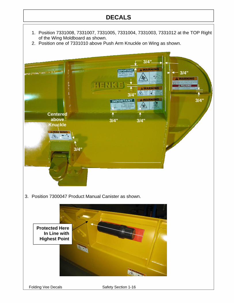
1. Position 7331008, 7331007, 7331005, 7331004, 7331003, 7331012 at the TOP Right
of the Wing Moldboard as shown. 2. Position one of 7331010 above Push Arm Knuckle on Wing as shown.
3. Position 7300047 Product Manual Canister as shown.
3/4"
3/4"
Centered above
Knuckle 3/4" 3/4"
3/4"
3/4"
3/4"
Protected Here In Line with
Highest Point
DECALS
Folding Vee Decals Safety Section 1-17
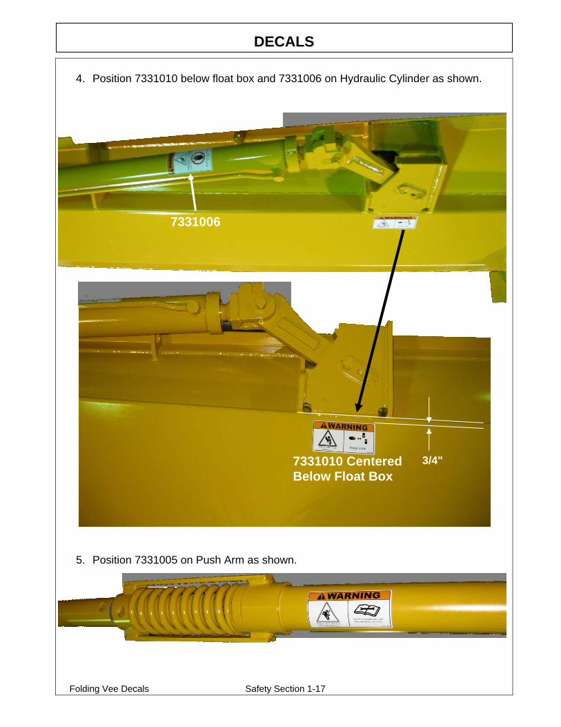
4. Position 7331010 below float box and 7331006 on Hydraulic Cylinder as shown.
5. Position 7331005 on Push Arm as shown.
7331006
7331010 Centered Below Float Box
3/4"

DECALS
Folding Vee Decals Safety Section 1-18
6. Position 7331010 on post as shown.
7. Position 7331006 decal on Post as shown.
Outboard Side of
Post
Centered In Given
Above Bottom
Rib
Rear Side of Post

AHW_CASE_845TO885_NH_RG140TORG200_EFF_JAN2013_TO_PRES_8510301_02_033.DOCXPage 7 of 67
In Season Maintenance
Snow removal equipment must be cared for and maintained regularly. Daily or pre-route inspection and maintenance are necessary. Failure to do so may affect efficiency and safety. A visual inspection must be carried out after every 8 hours of operation. Look for damaged components, bends, cracked welds or hydraulic leaks. REPAIR IMMEDIATELY! It is recommended to re-torque all bolts after the first 8 hours of use and to regularly check for loosened or missing fasteners. Replace any damaged or missing fasteners immediately. Because of the environment in which snow equipment is expected to operate, hydraulic lines, fasteners, wearable or replaceable items and warning decals may become damaged by snow, ice and road debris. These items must be inspected daily and replaced if necessary to avoid equipment damage or personal injury. Lubrication of moving parts is of the utmost importance. Exposure to snow, ice, salt and road debris will wash away lubrication quickly and it may be necessary to inspect and reapply lubrication more than once a day.

AHW_CASE_845TO885_NH_RG140TORG200_EFF_JAN2013_TO_PRES_8510301_02_033.DOCXPage 8 of 67
End of Season Maintenance
GROUND ENGAGING COMPONENTS CUTTING EDGES & GUARDS Replace any broken cutting edges, unevenly or excessively worn cutting edges, and
broken or worn wear guards. RUNNING GEAR Replace broken, worn, or missing running gear shoes, and any damaged adjuster leg
components. Grease internal threads and sliding members (it’s best to disassemble and grease directly; zerks aren’t as effective at greasing these areas).
HARDWARE Replace missing or broken bolts. Proper torque is important! Use grade 8 plow bolts
for steel cutting edges.
HYDRAULICS HOSES Plug or cap any QC fittings or any open hose ends. Inspect hoses for any leaks or
potential leaks. Secure hoses with hose clamps. CYLINDERS Check for leaks, and any chrome rod dents or scratches. Apply a light coat of oil or
grease on exposed rod surfaces.
FRAME AND MOLDBOARD JOINTS
Check pins, bushings, and pivot bolts for wear. Make sure all keepers are in place. Make sure shear bolts and pins are same as original equipment (usually grade 2). Some drivers don’t like replacing shear pins and will install grade 8 replacements to avoid replacing during a storm. These items are designed to shear to protect the driver and the equipment. CHECK WELDMENTS FOR CRACKS.
REPLACE WORN OR BROKEN PARTS FOUND BY ABOVE INSPECTIONS.
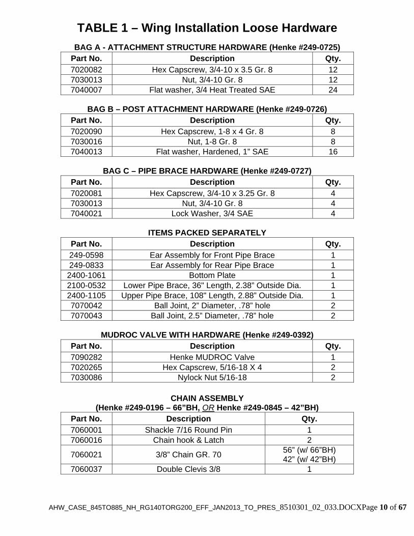
The installation hardware provided for the All Hydraulic Wing is listed below. If any hardware is missing please contact Henke Manufacturing Corporation. All installation hardware is yellow zinc plated for long-term corrosion resistance.

AHW_CASE_845TO885_NH_RG140TORG200_EFF_JAN2013_TO_PRES_8510301_02_033.DOCXPage 9 of 67
<THIS PAGE IS INTENTIONALLY LEFT BLANK>
AHW_CASE_845TO885_NH_RG140TORG200_EFF_JAN2013_TO_PRES_8510301_02_033.DOCXPage 10 of 67
BAG A - ATTACHMENT STRUCTURE HARDWARE (Henke #249-0725) Part No. Description Qty. 7020082 Hex Capscrew, 3/4-10 x 3.5 Gr. 8 12 7030013 Nut, 3/4-10 Gr. 8 12 7040007 Flat washer, 3/4 Heat Treated SAE 24
BAG B – POST ATTACHMENT HARDWARE (Henke #249-0726)
Part No. Description Qty. 7020090 Hex Capscrew, 1-8 x 4 Gr. 8 8 7030016 Nut, 1-8 Gr. 8 8 7040013 Flat washer, Hardened, 1” SAE 16
BAG C – PIPE BRACE HARDWARE (Henke #249-0727)
Part No. Description Qty. 7020081 Hex Capscrew, 3/4-10 x 3.25 Gr. 8 4 7030013 Nut, 3/4-10 Gr. 8 4 7040021 Lock Washer, 3/4 SAE 4
ITEMS PACKED SEPARATELY
Part No. Description Qty. 249-0598 Ear Assembly for Front Pipe Brace 1 249-0833 Ear Assembly for Rear Pipe Brace 1 2400-1061 Bottom Plate 1 2100-0532 Lower Pipe Brace, 36" Length, 2.38” Outside Dia. 1 2400-1105 Upper Pipe Brace, 108" Length, 2.88” Outside Dia. 1 7070042 Ball Joint, 2” Diameter, .78” hole 2 7070043 Ball Joint, 2.5” Diameter, .78” hole 2
MUDROC VALVE WITH HARDWARE (Henke #249-0392)
Part No. Description Qty. 7090282 Henke MUDROC Valve 1 7020265 Hex Capscrew, 5/16-18 X 4 2 7030086 Nylock Nut 5/16-18 2
CHAIN ASSEMBLY
(Henke #249-0196 – 66”BH, OR Henke #249-0845 – 42”BH) Part No. Description Qty. 7060001 Shackle 7/16 Round Pin 1 7060016 Chain hook & Latch 2
7060021 3/8” Chain GR. 70 56” (w/ 66”BH) 42” (w/ 42”BH)
7060037 Double Clevis 3/8 1
TABLE 1 – Wing Installation Loose Hardware

AH
W_C
AS
E_845T
O885_N
H_R
G140T
OR
G200_E
FF
_JAN
2013_TO
_PR
ES
_8510301_02_033.DO
CX
Page 11 of 67
FIGURE 2 – Front Post Assembly & Attachments

AHW_CASE_845TO885_NH_RG140TORG200_EFF_JAN2013_TO_PRES_8510301_02_033.DOCXPage 12 of 67
Item No. Qty. Part No. Description
1 1249-0706249-0574
Slide Assembly, 42"BH orSlide Assembly, 66"BH
2 1 249-0215 Banjo Hinge Pin Assembly3 1 7020131 Hex Capscrew, 5/8-11 x 2.75 GR. 84 13 7030084 Toplock Nut, 5/8-11 GR. C5 1 249-0188 Knuckle Pin Assembly6 1 7040004 Flat Washer, 3/8 Hardened, USS7 1 7040018 Lock Washer, 3/88 1 7020029 Hex Capscrew, 3/8-16 x 1 GR. 59 2 7300006 Nylatron Slide Guide10 12 7020128 Hex Capscrew, 5/8-11 x 4.5 GR. 811 12 7040006 Flat Washer, 5/8
12 1249-0887249-0588
Post Assembly, 42"BH orPost Assembly, 66"BH
13 1 249-0590 Attaching Structure Assembly14 8 7020090 Hex Capscrew, 1-8 x 4 GR. 815 16 7040013 Flat Washer, 1” Hardened, SAE16 8 7030016 Nut, 1-8 GR. 817 1 2400-1061 Weld-On Mounting Plate18 12 7020082 Hex Capscrew, 3/4-10 x 3.5 GR. 819 24 7040007 Flat Washer, 3/4 Hardened, SAE20 16 7030013 Nut, 3/4-10 GR. 8
21 170808117080809
Hydraulic Cylinder, 3.5 x 42 x 1.75, 42"BHHydraulic Cylinder, 3.5 x 66 x 1.75, 66"BH
22 1 7040024 Flat Washer, 1 1/2 Hardened, SAE23 1 7030024 Slotted Nut, 1 1/2-6 GR. 224 1 7050001 Cotter Pin, 1/4 x 325 1 249-0200 Pin Assembly26 1 7050003 Cotter Pin, 3/16 x 227 2 7070042 Ball Joint, 2” dia. with 0.78” Hole28 1 249-0598 Pipe Brace Ear Assembly, Front29 1 249-0833 Pipe Brace Ear Assembly, Rear30 2 7070043 Ball Joint, 2.5” dia.with 0.78” hole31 1 2100-0532 Pipe Brace, 36”32 1 2400-1105 Pipe Brace, Large, 108”33 4 7020081 Hex Capscrew, 3/4-10 x 3.25 GR. 834 4 7040021 Lock Washer, 3/435 2 7090111 Grease Fitting, Straight, 1/4-2836 2 2400-1054 Slide Keeper (Purchased as part of Item #1)50 1 249-0192 Banjo Hinge Assembly (Also shown in Fig. 3)52 1 249-0185 Knuckle Assembly (Also shown in Fig. 3)
Not Shown 1249-0845249-0196
Safety Chain Assembly 42"BHSafety Chain Assembly 66"BH
Not Shown 6 7050048 Roll Pin for Slide Assembly
TABLE 2 – Front Post Assembly & Attachments, Parts List This list is important and should be referred to when ordering replacement parts from your local dealer or Henke Manufacturing Corporation. The parts diagram for the front post assembly is shown in Figure 2.
AHW_CASE_845TO885_NH_RG140TORG200_EFF_JAN2013_TO_PRES_8510301_02_033.DOCXPage 13 of 67
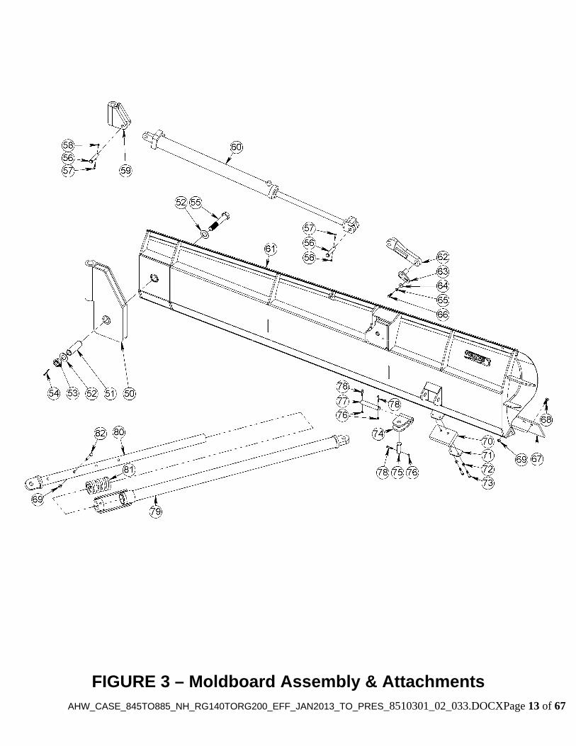
FIGURE 3 – Moldboard Assembly & Attachments

AHW_CASE_845TO885_NH_RG140TORG200_EFF_JAN2013_TO_PRES_8510301_02_033.DOCXPage 14 of 67
This list is important and should be referred to when ordering replacement parts from your local dealer or Henke Manufacturing Corporation. The parts diagram for the
moldboard and push tube assemblies is shown in Figure 2.
TABLE 3 – Moldboard Assembly & Attachments, Parts List
Item No. Qty. Part No. Description50 1 249-0192 Banjo Hinge Assembly51 1 2400-0062 Hinge Plate Bushing52 2 7040024 Flat Washer, 1 1/2 Hardened, SAE53 1 7030024 Slotted Nut, 1 1/2-654 1 7050001 Cotter Pin, 1/4 x 355 1 2400-0183 Moldboard Attaching Bolt56 2 2400-1870 Clevis Pin, 1 . 4.5, Modified 57 2 7020019 Hex Capscrew, 5/16-18 X 1.5 GR. 558 2 7030086 Nylock Nut, 5/16-1859 1 249-0185 Knuckle Assembly60 1 7080808 Hydraulic Cylinder, 3.5 x 37.5 x 1.75N/A N/A 7080908 Seal Kit for Cylinder 7080808
61 1
249-0705249-0878249-0199249-0209
Moldboard Assembly, 10'Moldboard Assembly, 11'Moldboard Assembly, 12'Moldboard Assembly, 14'
62 1 249-0189 Float Link Assembly63 1 139-0918 Float Link Pin Assembly64 1 7040005 Flat Washer, 1/2 Hardened, SAE65 1 7040019 Lock Washer, ½66 1 7020130 Hex Capscrew, 1/2-13 x 1.5 GR. 867 Varies Varies Cutting Edge (1/2 x 8 Standard)68 Varies Varies Plow Bolt, 5/8-11 GR. 869 Varies 7030084 Toplock Nut, 5/8-11 GR. C70 1 2000-0126 Bumper71 1 2000-0125 Bumper Bracket72 2 7030031 Toplock Nut, 1/2-13 GR. C73 2 7020051 Hex Capscrew, 1/2-13 x 3.5 GR. 574 1 249-0193 Pushbeam Moldboard Joint75 1 2400-1784 Clevis Pin, 1-1/4 x 3.5 AHW76 3 7030006 Nylock Nut, 3/8-1677 1 2300-0160 Pin, 1.25 x 778 3 7020034 Hex Capscrew, 3/8-16 x 2
79 1
249-0777
249-0783
Outer Tube Assembly, Std Length(Rear Ripper Machines Only)
Outer Tube Assembly, Short Length(Fixed and Elevating Rear Machines)
80 1 249-0779 Inner Tube Assembly81 1 7070103 Compression Spring82 1 7020500 Hex Capscrew, 5/8-11 x 5.5
AHW_CASE_845TO885_NH_RG140TORG200_EFF_JAN2013_TO_PRES_8510301_02_033.DOCXPage 15 of 67
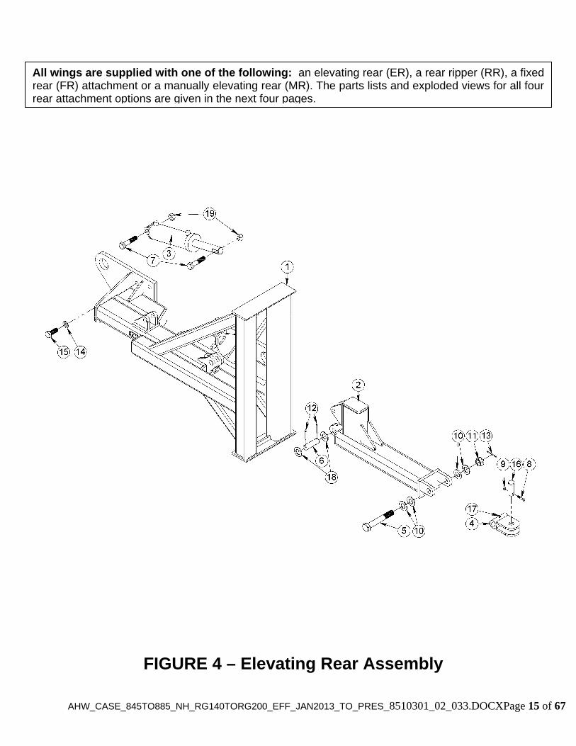
FIGURE 4 – Elevating Rear Assembly
All wings are supplied with one of the following: an elevating rear (ER), a rear ripper (RR), a fixed rear (FR) attachment or a manually elevating rear (MR). The parts lists and exploded views for all four rear attachment options are given in the next four pages.
AHW_CASE_845TO885_NH_RG140TORG200_EFF_JAN2013_TO_PRES_8510301_02_033.DOCXPage 16 of 67
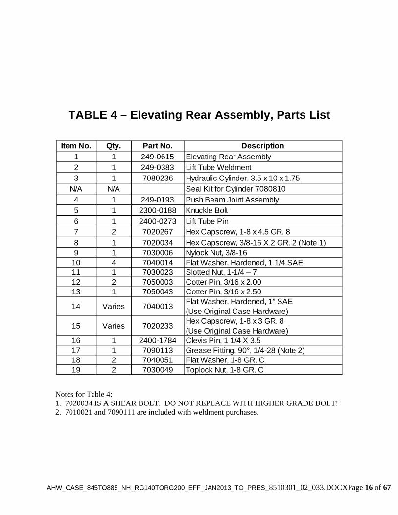
TABLE 4 – Elevating Rear Assembly, Parts List
Item No. Qty. Part No. Description
1 1 249-0615 Elevating Rear Assembly2 1 249-0383 Lift Tube Weldment3 1 7080236 Hydraulic Cylinder, 3.5 x 10 x 1.75
N/A N/A Seal Kit for Cylinder 70808104 1 249-0193 Push Beam Joint Assembly5 1 2300-0188 Knuckle Bolt6 1 2400-0273 Lift Tube Pin7 2 7020267 Hex Capscrew, 1-8 x 4.5 GR. 88 1 7020034 Hex Capscrew, 3/8-16 X 2 GR. 2 (Note 1)9 1 7030006 Nylock Nut, 3/8-16
10 4 7040014 Flat Washer, Hardened, 1 1/4 SAE11 1 7030023 Slotted Nut, 1-1/4 – 712 2 7050003 Cotter Pin, 3/16 x 2.0013 1 7050043 Cotter Pin, 3/16 x 2.50
14 Varies 7040013Flat Washer, Hardened, 1” SAE(Use Original Case Hardware)
15 Varies 7020233Hex Capscrew, 1-8 x 3 GR. 8(Use Original Case Hardware)
16 1 2400-1784 Clevis Pin, 1 1/4 X 3.517 1 7090113 Grease Fitting, 90°, 1/4-28 (Note 2)18 2 7040051 Flat Washer, 1-8 GR. C19 2 7030049 Toplock Nut, 1-8 GR. C
Notes for Table 4: 1. 7020034 IS A SHEAR BOLT. DO NOT REPLACE WITH HIGHER GRADE BOLT! 2. 7010021 and 7090111 are included with weldment purchases.
AHW_CASE_845TO885_NH_RG140TORG200_EFF_JAN2013_TO_PRES_8510301_02_033.DOCXPage 17 of 67
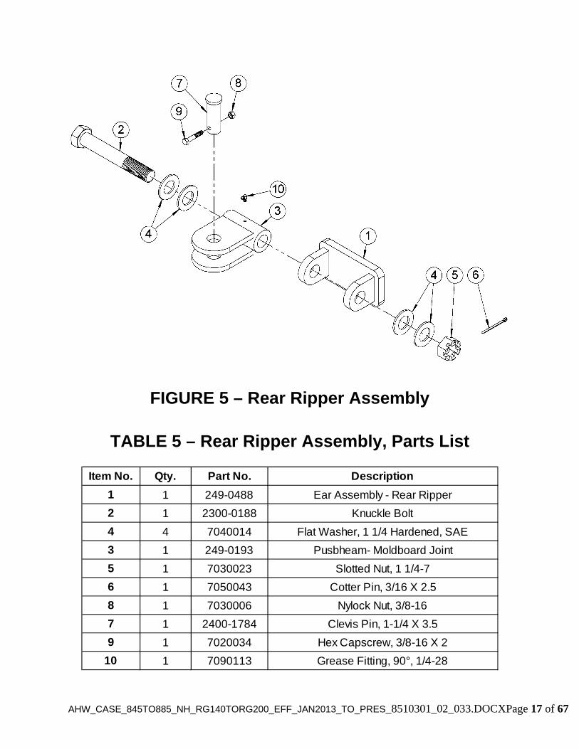
FIGURE 5 – Rear Ripper Assembly
TABLE 5 – Rear Ripper Assembly, Parts List
Item No. Qty. Part No. Description
1 1 249-0488 Ear Assembly - Rear Ripper
2 1 2300-0188 Knuckle Bolt
4 4 7040014 Flat Washer, 1 1/4 Hardened, SAE
3 1 249-0193 Pusbheam- Moldboard Joint
5 1 7030023 Slotted Nut, 1 1/4-7
6 1 7050043 Cotter Pin, 3/16 X 2.5
8 1 7030006 Nylock Nut, 3/8-16
7 1 2400-1784 Clevis Pin, 1-1/4 X 3.5
9 1 7020034 Hex Capscrew, 3/8-16 X 2
10 1 7090113 Grease Fitting, 90°, 1/4-28
AHW_CASE_845TO885_NH_RG140TORG200_EFF_JAN2013_TO_PRES_8510301_02_033.DOCXPage 18 of 67
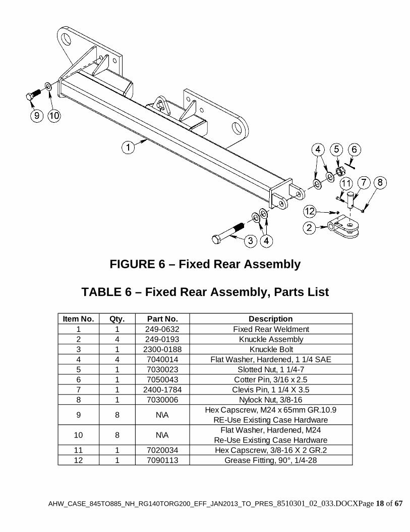
FIGURE 6 – Fixed Rear Assembly
TABLE 6 – Fixed Rear Assembly, Parts List
Item No. Qty. Part No. Description1 1 249-0632 Fixed Rear Weldment2 4 249-0193 Knuckle Assembly3 1 2300-0188 Knuckle Bolt4 4 7040014 Flat Washer, Hardened, 1 1/4 SAE5 1 7030023 Slotted Nut, 1 1/4-76 1 7050043 Cotter Pin, 3/16 x 2.57 1 2400-1784 Clevis Pin, 1 1/4 X 3.58 1 7030006 Nylock Nut, 3/8-16
9 8 N\AHex Capscrew, M24 x 65mm GR.10.9
RE-Use Existing Case Hardware
10 8 N\AFlat Washer, Hardened, M24
Re-Use Existing Case Hardware11 1 7020034 Hex Capscrew, 3/8-16 X 2 GR.212 1 7090113 Grease Fitting, 90°, 1/4-28
AH
W_C
AS
E_845T
O885_N
H_R
G140T
OR
G200_E
FF
_JAN
2013_TO
_PR
ES
_8510301_02_033.DO
CX
Page 19 of 67
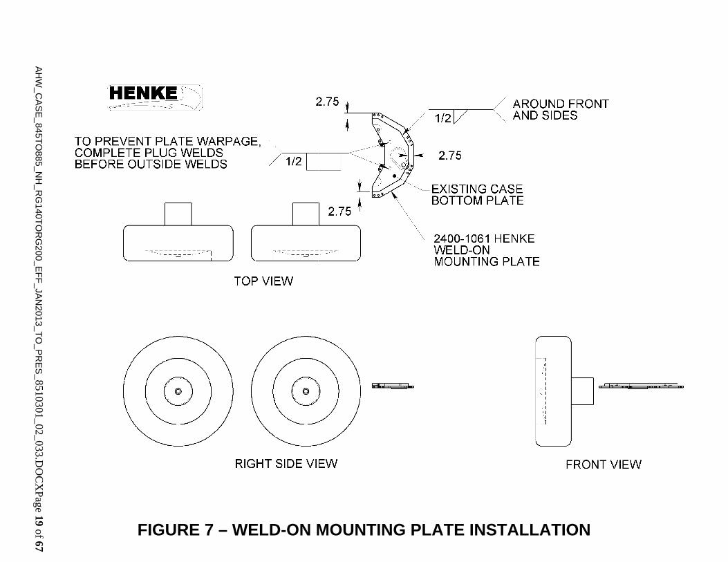
FIGURE 7 – WELD-ON MOUNTING PLATE INSTALLATION
AHW_CASE_845TO885_NH_RG140TORG200_EFF_JAN2013_TO_PRES_8510301_02_033.DOCXPage 20 of 67
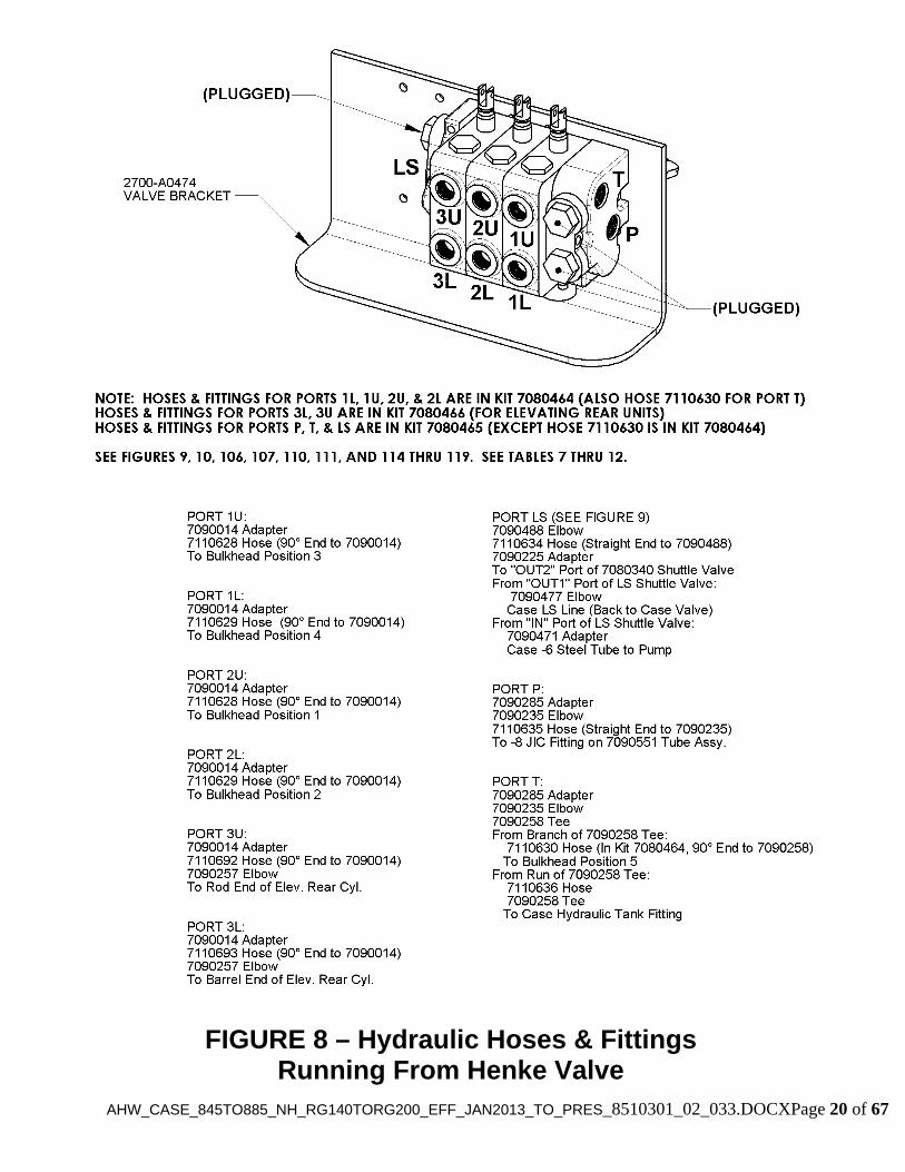
FIGURE 8 – Hydraulic Hoses & Fittings Running From Henke Valve
AHW_CASE_845TO885_NH_RG140TORG200_EFF_JAN2013_TO_PRES_8510301_02_033.DOCXPage 21 of 67
FIGURE 9 – Plumbing of 7080340 Load Sense Shuttle Valve
AH
W_C
AS
E_845T
O885_N
H_R
G140T
OR
G200_E
FF
_JAN
2013_TO
_PR
ES
_8510301_02_033.DO
CX
Page
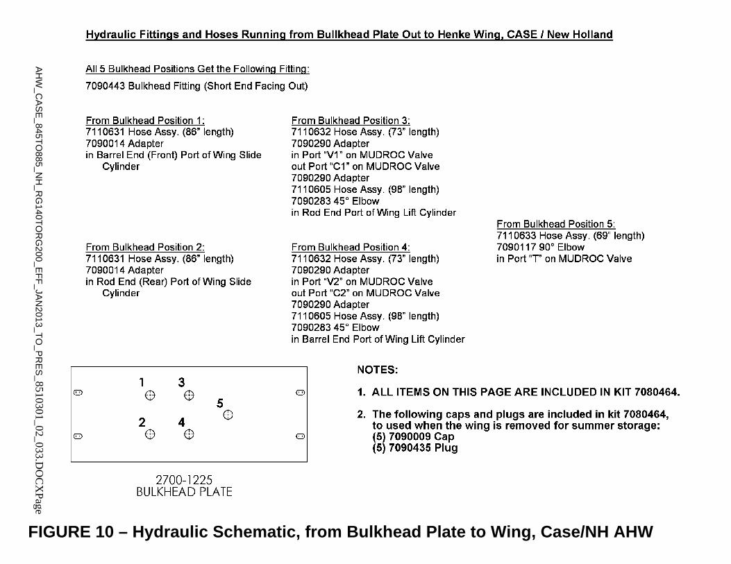
FIGURE 10 – Hydraulic Schematic, from Bulkhead Plate to Wing, Case/NH AHW
AHW_CASE_845TO885_NH_RG140TORG200_EFF_JAN2013_TO_PRES_8510301_02_033.DOCXPage 23 of 67
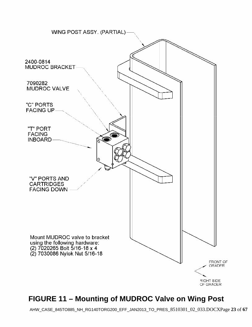
FIGURE 11 – Mounting of MUDROC Valve on Wing Post
AHW_CASE_845TO885_NH_RG140TORG200_EFF_JAN2013_TO_PRES_8510301_02_033.DOCXPage 24 of 67
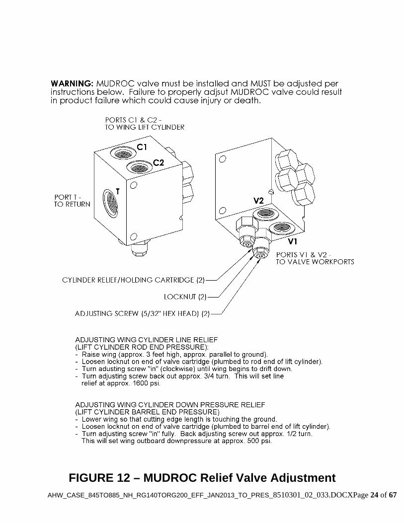
FIGURE 12 – MUDROC Relief Valve Adjustment

AHW_CASE_845TO885_NH_RG140TORG200_EFF_JAN2013_TO_PRES_8510301_02_033.DOCXPage 25 of 67
TABLE 7 – 2-Section Valve & Controls Kit
Henke Kit No. 6182602
Note:
1. All hose assembly lengths are total lengths which include the fittings.
Qty. Part No. Description1 7080098 Hydraulic Valve, Load Sense, 2-Section1 279-0474 Valve Bracket Assembly1 7080340 Load Sense Shuttle Valve1 2700-1225 Bulkhead Plate2 2700-1278 Control Handle, Bent2 7080502 Control Cable, 66”2 7080119 Remote Valve Control Kit (“Bonnet Kit”)1 279-0503 Handle Bracket Assembly2 7090558 Clamp Pair, Beringer PP-H41001 7090559 Clamp Cover Plate, Beringer DCP-H44 7020314 Hex Capscrew, 3/8-16 x 2.25 Gr. 53 7020024 Hex Capscrew, 5/16-18 x 3 Gr. 26 7030086 Nylock Nut, 5/16-18 Gr. 24 7020063 Hex Capscrew, 5/8-11 x 3.5 Gr. 24 7030084 Toplock Nut, 5/8-11 Gr. C8 7040006 Flat Washer, Hardened, 5/8 SAE1 7300037 Decal Sheet – “Wing”1 7300038 Decal Sheet – “Plow”3 7020125 Hex Capscrew, 5/16-18 x 4.5 Gr. 22 7210018 Cable Tie, .30 x 24”, UV Black

AHW_CASE_845TO885_NH_RG140TORG200_EFF_JAN2013_TO_PRES_8510301_02_033.DOCXPage 26 of 67
TABLE 8 – 3-Section Valve & Controls Kit
Henke Kit No. 6182603
Note:
1. All hose assembly lengths are total lengths which include the fittings.
Qty. Part No. Description1 7080351 Hydraulic Valve, Load Sense, 3-Section1 279-0474 Valve Bracket Assembly1 7080340 Load Sense Shuttle Valve1 2700-1225 Bulkhead Plate3 2700-1278 Control Handle, Bent3 7080502 Control Cable, 66”3 7080119 Remote Valve Control Kit (“Bonnet Kit”)1 279-0503 Handle Bracket Assembly2 7090558 Clamp Pair, Beringer PP-H41001 7090559 Clamp Cover Plate, Beringer DCP-H44 7020314 Hex Capscrew, 3/8-16 x 2.25 Gr. 53 7020024 Hex Capscrew, 5/16-18 x 3 Gr. 26 7030086 Nylock Nut, 5/16-18 Gr. 24 7020063 Hex Capscrew, 5/8-11 x 3.5 Gr. 24 7030084 Toplock Nut, 5/8-11 Gr. C8 7040006 Flat Washer, Hardened, 5/8 SAE1 7300037 Decal Sheet – “Wing”1 7300038 Decal Sheet – “Plow”3 7020125 Hex Capscrew, 5/16-18 x 4.5 Gr. 22 7210018 Cable Tie, .30 x 24”, UV Black

AHW_CASE_845TO885_NH_RG140TORG200_EFF_JAN2013_TO_PRES_8510301_02_033.DOCXPage 27 of 67
TABLE 9 – Special 3-Section Valve & Controls Kit with Detent on Wing Slide & Wing Lift
Henke Kit No. 6182604
Note:
1. All hose assembly lengths are total lengths which include the fittings.
Qty. Part No. Description1 7080578 Hydraulic Valve, Load Sense, 3-Section w/2 Detents1 279-0474 Valve Bracket Assembly1 7080340 Load Sense Shuttle Valve1 2700-1225 Bulkhead Plate3 2700-1278 Control Handle, Bent3 7080502 Control Cable, 66”3 7080119 Remote Valve Control Kit (“Bonnet Kit”)1 279-0503 Handle Bracket Assembly2 7090558 Clamp Pair, Beringer PP-H41001 7090559 Clamp Cover Plate, Beringer DCP-H44 7020314 Hex Capscrew, 3/8-16 x 2.25 Gr. 53 7020024 Hex Capscrew, 5/16-18 x 3 Gr. 26 7030086 Nylock Nut, 5/16-18 Gr. 24 7020063 Hex Capscrew, 5/8-11 x 3.5 Gr. 24 7030084 Toplock Nut, 5/8-11 Gr. C8 7040006 Flat Washer, Hardened, 5/8 SAE1 7300037 Decal Sheet – “Wing”1 7300038 Decal Sheet – “Plow”3 7020125 Hex Capscrew, 5/16-18 x 4.5 Gr. 22 7210018 Cable Tie, .30 x 24”, UV Black

AHW_CASE_845TO885_NH_RG140TORG200_EFF_JAN2013_TO_PRES_8510301_02_033.DOCXPage 28 of 67
TABLE 10 – Hydraulic Tie-In Kit
Henke Kit No. 6182600
Note:
1. All hose assembly lengths are total lengths which include the fittings.
2. Items marked with an * are included in Henke Kit 7080465.
Qty. Part No. Description1 7110634* Hose Assembly, 3/8-2 x 36”, -6 JIC F x -6 JIC F 90° Elbow
1 7110635*Hose Assembly, 1/2-2 x 24.5", -8 JIC F x -8 JIC F 90° Tube Elbow (Long Drop)
1 7110636* Hose Assembly, 1/2-2 x 110", -8 JIC F e/e2 7090235* Elbow, 90, -8 JIC M x -8 JIC F2 7090285* Straight Adapter, -8 JIC M x -12 ORB M2 7090258* Tee, -8 JIC M, -8 JIC F Run1 7090488* Elbow, 90, -6 JIC M x -4 ORB Adj. M1 7090225* Straight Adapter, -6 JIC M x -6 ORB M1 7090477* Elbow, 90, -6 JIC M x -6 ORB Adj. M1 7090471* Straight Adapter, -6 ORB M x -6 JIC F1 7090009* Cap, -8 JIC1 7090551 Custom Tube Assembly (design on file at Tompkins)

AHW_CASE_845TO885_NH_RG140TORG200_EFF_JAN2013_TO_PRES_8510301_02_033.DOCXPage 29 of 67
TABLE 11 – Cylinder Hose Kit
Henke Kit No. 6182609
Note:
1. All hose assembly lengths are total lengths which include the fittings.
2. All Items marked with an * are included in Henke Kit 7080464.
Qty. Part No. Description
2 7110605*Hose Assembly, 98", -8 JIC F e/e, Nylon Sleeve Full Length
2 7110596*Hose Assembly, 62", -8 JIC F x -8 JIC F 90° Tube Elbow (Short Drop)
2 7110808*Hose Assembly, 64", -8 JIC F x –8 JIC F 90° Tube Elbow (Long Drop), Nylon Sleeve Full Length
1 7110809*Hose Assembly, 57", -8 JIC F x –8 JIC F 90° Tube Elbow (Short Drop)
2 7110810*Hose Assembly, 86", -8 JIC F x –8 JIC F 90° Tube Elbow (Long Drop), Nylon Sleeve Full Length
2 7110811*Hose Assembly, 73", -8 JIC F x –8 JIC F 90° Tube Elbow (Short Drop), Nylon Sleeve Full Length
1 7110812*Hose Assembly, 69", -8 JIC F x –8 JIC F 90° Tube Elbow (Short Drop), Nylon Sleeve Full Length
6 7090014* Straight Adapter, -8 JIC M x –10 ORB M5 7090443* Bulkhead Fitting, -8 JIC M4 7090290* Straight Adapter, -8 JIC M x –8 ORB M1 7090117* Elbow, 90, -8 JIC M x –10 ORB Adj. M2 7090283* Elbow, 45, -8 JIC M x –8 ORB Adj. M5 7090009* Cap, -8 JIC5 7090435* Plug, -8 JIC1 7090493* Clamp Pair (must be marked “3087” or “7/8T”)1 7090429* Cover Plate1 7020277* Bolt, 5/16-18 x 1.75, GR. 2, Zinc Plated1 2700-1433 Valve Bracket for 7080344

AHW_CASE_845TO885_NH_RG140TORG200_EFF_JAN2013_TO_PRES_8510301_02_033.DOCXPage 30 of 67
TABLE 12 – Elevating Rear Hose Kit
Henke Kit No. 7080466
Note:
1. All hose assembly lengths are total lengths which include the fittings.
Qty. Part No. Description
1 7110692Hose Assembly, 221", -8 JIC F x -8 JIC F 90° Tube
Elbow (Short Drop)
1 7110693Hose Assembly, 213", -8 JIC F x –8 JIC F 90° Tube
Elbow (Long Drop)2 7090014 Straight Adapter, -8 JIC M x –10 ORB M2 7090257 Elbow, 90, -8 JIC M x –8 ORB Adj. M1 7090428 Clamp Pair (must be marked “30840” or “1/2P”)1 7090429 Cover Plate1 7020277 Bolt, 5/16-18 x 1.75, Gr. 2, Zinc Plated1 N/A Spiral Hose Wrap, Cut to 22” Length1 N/A Spiral Hose Wrap, Cut to 16” Length
AH
W_C
AS
E_845T
O885_N
H_R
G140T
OR
G200_E
FF
_JAN
2013_TO
_PR
ES
_8510301_02_033.DO
CX
Page 31 of 67
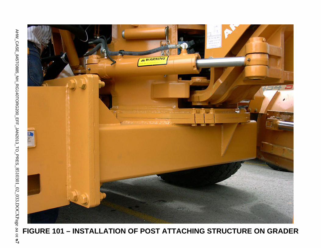
FIGURE 101 – INSTALLATION OF POST ATTACHING STRUCTURE ON GRADER

AH
W_C
AS
E_845T
O885_N
H_R
G140T
OR
G200_E
FF
_JAN
2013_TO
_PR
ES
_8510301_02_033.DO
CX
Page 32 of 67
Case Ears
249-0598 Front Pipe Brace Assembly
5.00”
1.75”
FIGURE 102 – FRONT PIPE BRACE EAR MOUNTING
AH
W_C
AS
E_845T
O885_N
H_R
G140T
OR
G200_E
FF
_JAN
2013_TO
_PR
ES
_8510301_02_033.DO
CX
Page 33 of 67
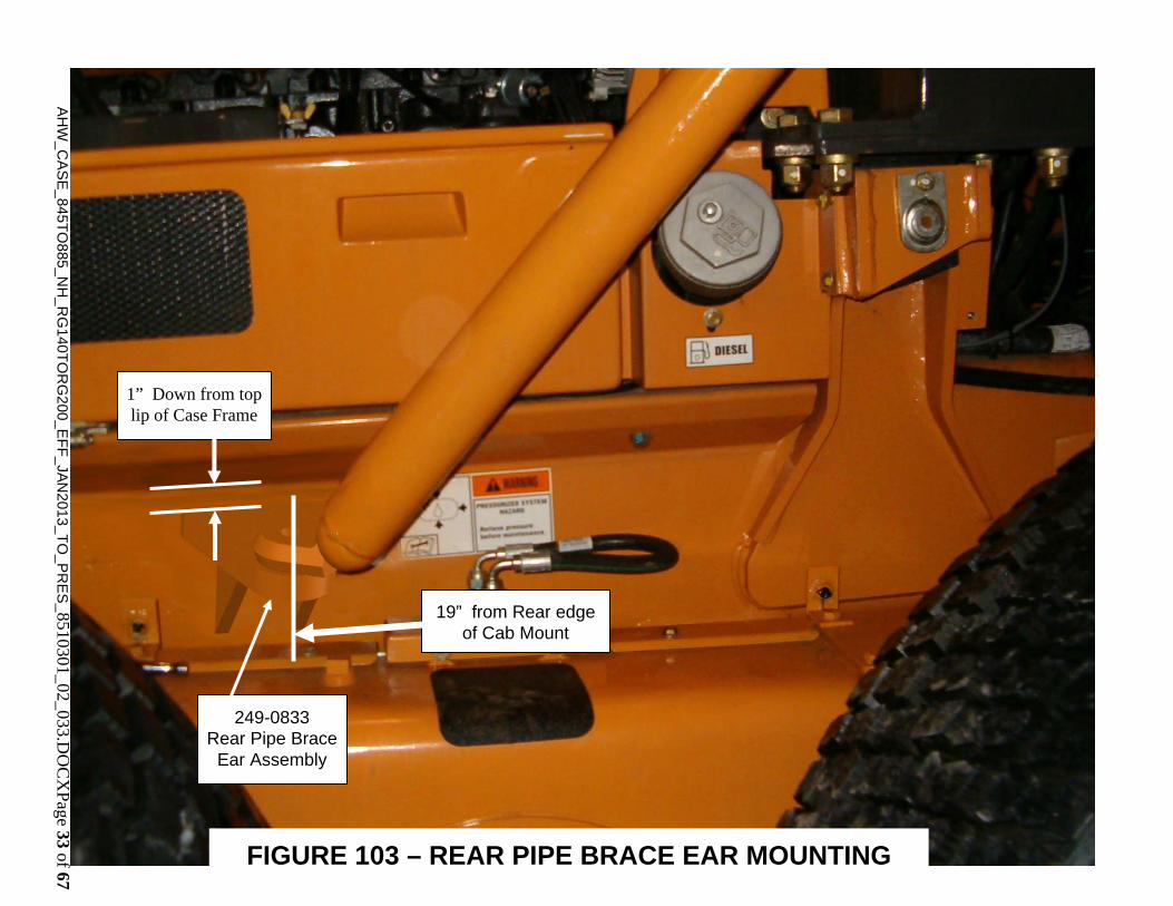
19” from Rear edge of Cab Mount
249-0833 Rear Pipe Brace
Ear Assembly
1” Down from top lip of Case Frame
FIGURE 103 – REAR PIPE BRACE EAR MOUNTING

AH
W_C
AS
E_845T
O885_N
H_R
G140T
OR
G200_E
FF
_JAN
2013_TO
_PR
ES
_8510301_02_033.DO
CX
Page 34 of 67
FIGURE 104 – FRONT PIPE BRACE MOUNTING

AHW_CASE_845TO885_NH_RG140TORG200_EFF_JAN2013_TO_PRES_8510301_02_033.DOCXPage 35 of 67
FIGURE 105 – REAR PIPE BRACE MOUNTING
AH
W_C
AS
E_845T
O885_N
H_R
G140T
OR
G200_E
FF
_JAN
2013_TO
_PR
ES
_8510301_02_033.DO
CX
Page 36 of 67
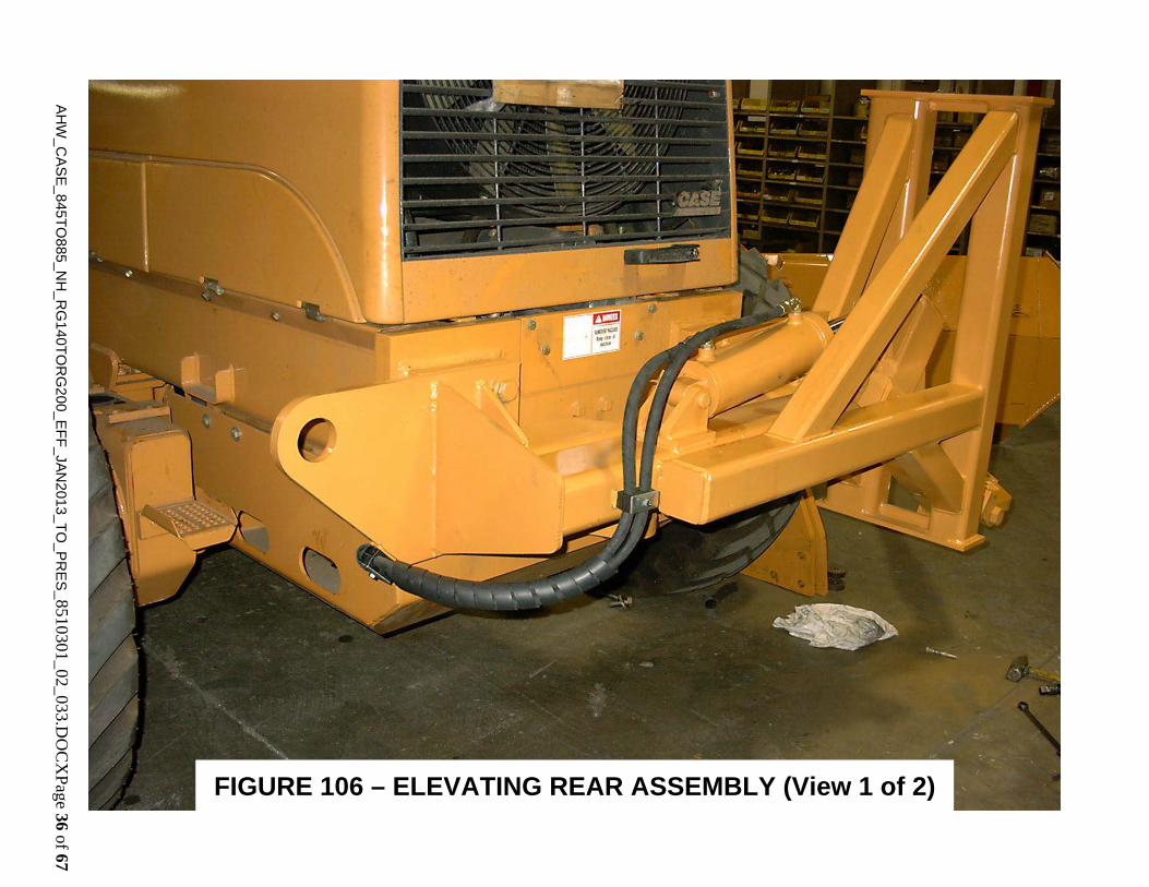
FIGURE 106 – ELEVATING REAR ASSEMBLY (View 1 of 2)
AHW_CASE_845TO885_NH_RG140TORG200_EFF_JAN2013_TO_PRES_8510301_02_033.DOCXPage 37 of 67
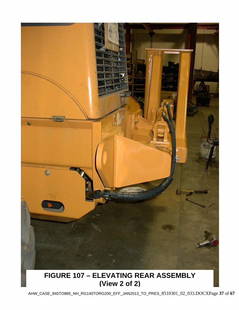
FIGURE 107 – ELEVATING REAR ASSEMBLY (View 2 of 2)

AH
W_C
AS
E_845T
O885_N
H_R
G140T
OR
G200_E
FF
_JAN
2013_TO
_PR
ES
_8510301_02_033.DO
CX
Page 38 of 67
FIGURE 108 – FIXED REAR ASSEMBLY

AH
W_C
AS
E_845T
O885_N
H_R
G140T
OR
G200_E
FF
_JAN
2013_TO
_PR
ES
_8510301_02_033.DO
CX
Page 39 of 67
FIGURE 109 – REAR RIPPER ATTACHMENT

AHW_CASE_845TO885_NH_RG140TORG200_EFF_JAN2013_TO_PRES_8510301_02_033.DOCXPage 40 of 67
Mudroc Return Hose 7110630
Main Return Hose7110636
Pressure Hose 7110635
FIGURE 110 – HENKE CONTROL VALVE MOUNTING (View 1 of 2)
AHW_CASE_845TO885_NH_RG140TORG200_EFF_JAN2013_TO_PRES_8510301_02_033.DOCXPage 41 of 67
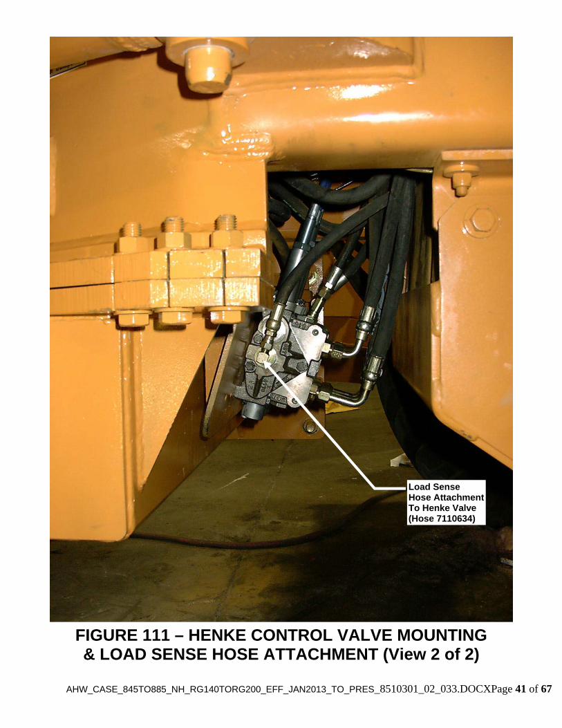
Load Sense Hose AttachmentTo Henke Valve (Hose 7110634)
FIGURE 111 – HENKE CONTROL VALVE MOUNTING & LOAD SENSE HOSE ATTACHMENT (View 2 of 2)
AH
W_C
AS
E_845T
O885_N
H_R
G140T
OR
G200_E
FF
_JAN
2013_TO
_PR
ES
_8510301_02_033.DO
CX
Page 42 of 67
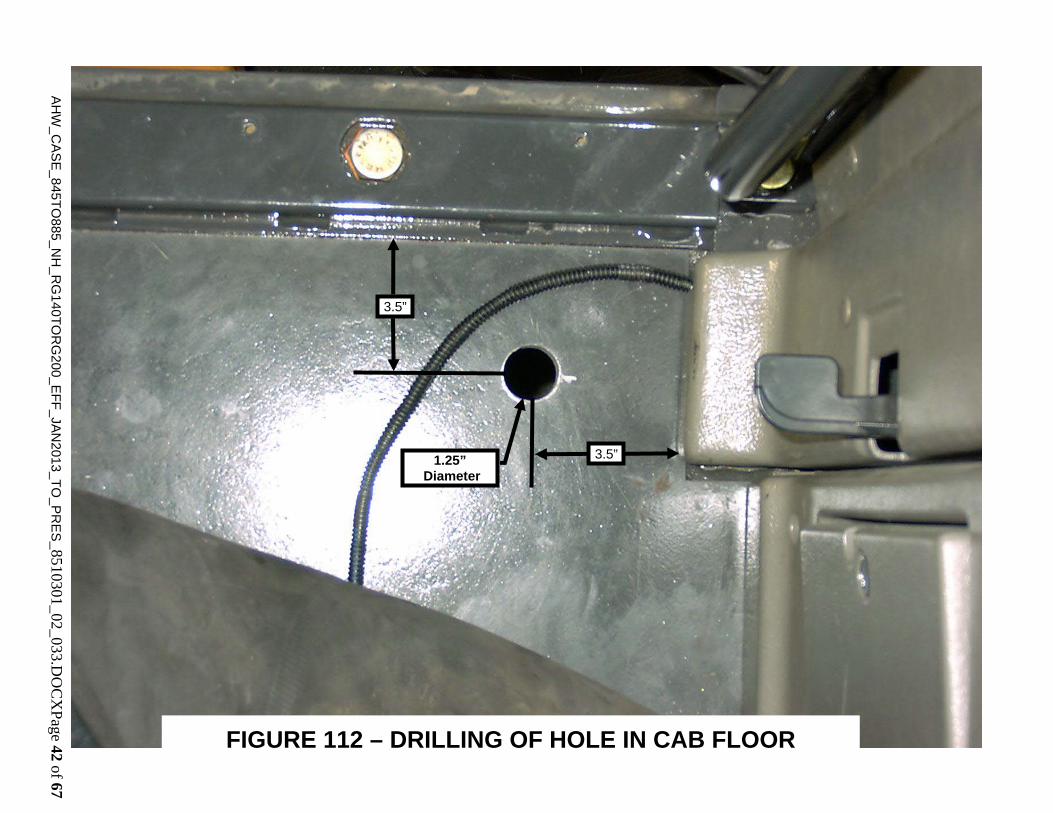
1.25” Diameter
3.5”
3.5”
FIGURE 112 – DRILLING OF HOLE IN CAB FLOOR
AH
W_C
AS
E_845T
O885_N
H_R
G140T
OR
G200_E
FF
_JAN
2013_TO
_PR
ES
_8510301_02_033.DO
CX
Page 43 of 67
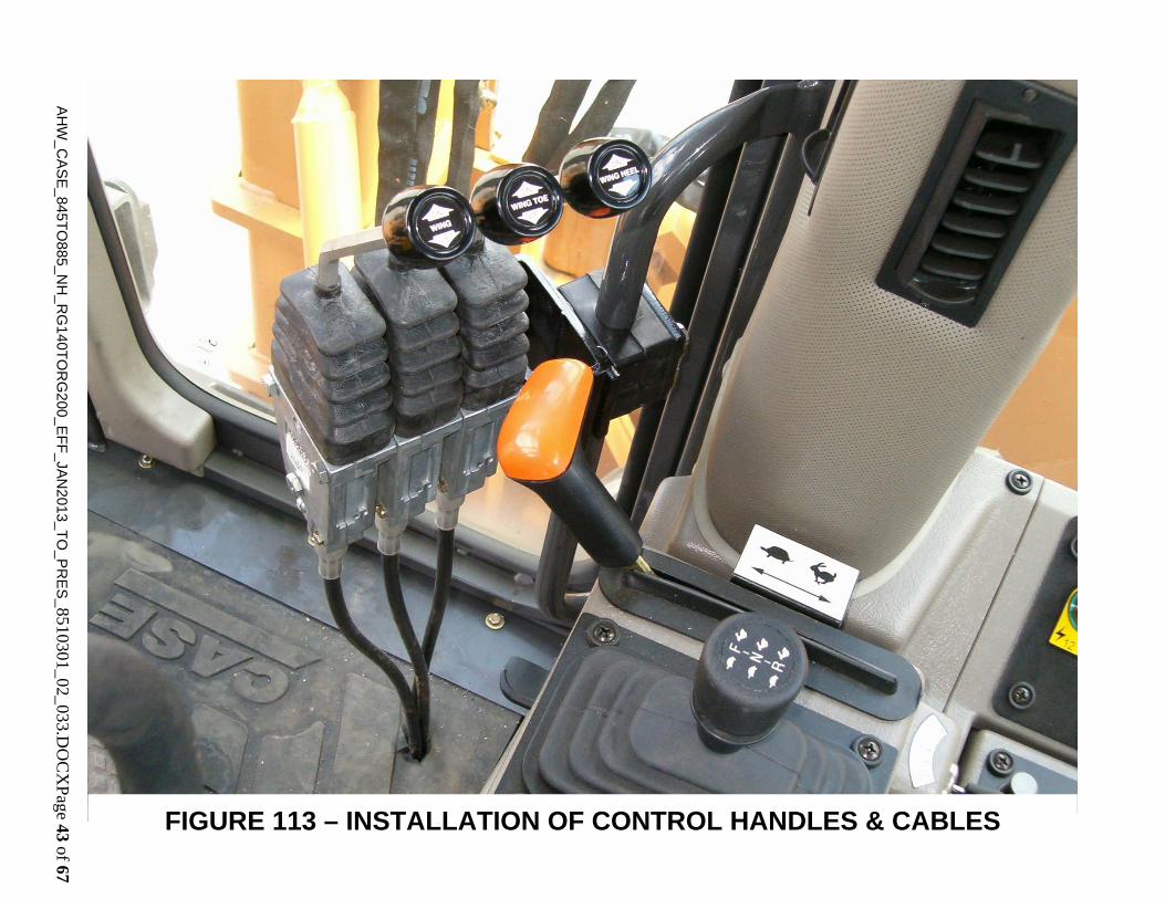
FIGURE 113 – INSTALLATION OF CONTROL HANDLES & CABLES

AH
W_C
AS
E_845T
O885_N
H_R
G140T
OR
G200_E
FF
_JAN
2013_TO
_PR
ES
_8510301_02_033.DO
CX
P
of 67
Load Sense Shuttle Valve
FIGURE 114 – INSTALLATION OF LOAD SENSE SHUTTLE VALVE (View 1 of 2)
AH
W_C
AS
E_845T
O885_N
H_R
G140T
OR
G200_E
FF
_JAN
2013_TO
_PR
ES
_8510301_02_033.DO
CX
Page 45 of 67
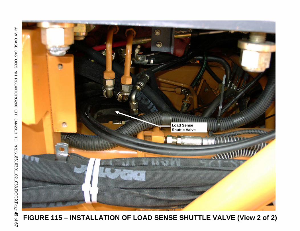
Load Sense Shuttle Valve
FIGURE 115 – INSTALLATION OF LOAD SENSE SHUTTLE VALVE (View 2 of 2)
AH
W_C
AS
E_845T
O885_N
H_R
G140T
OR
G200_E
FF
_JAN
2013_TO
_PR
ES
_8510301_02_033.DO
CX
Page 46 of 67
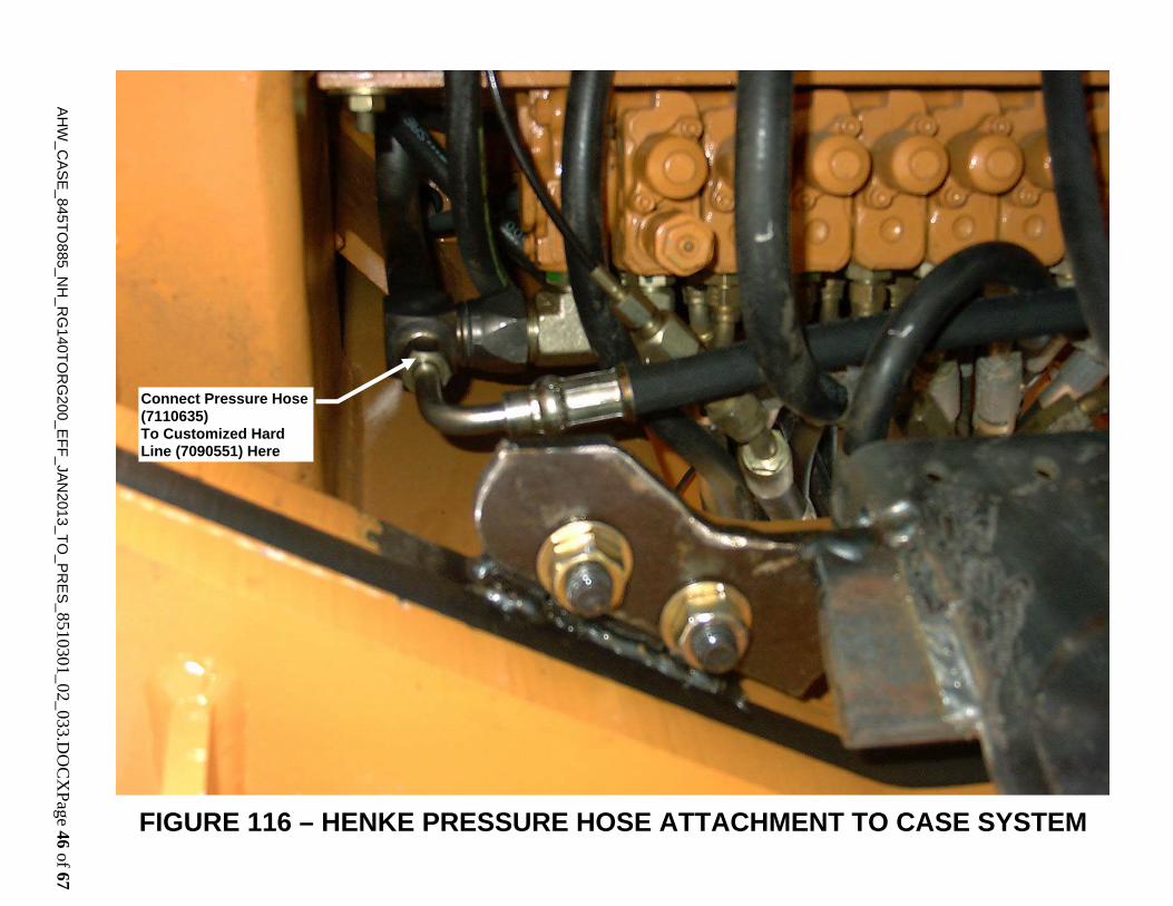
Connect Pressure Hose (7110635) To Customized Hard Line (7090551) Here
FIGURE 116 – HENKE PRESSURE HOSE ATTACHMENT TO CASE SYSTEM
AH
W_C
AS
E_845T
O885_N
H_R
G140T
OR
G200_E
FF
_JAN
2013_TO
_PR
ES
_8510301_02_033.DO
CX
Page 47 of 67
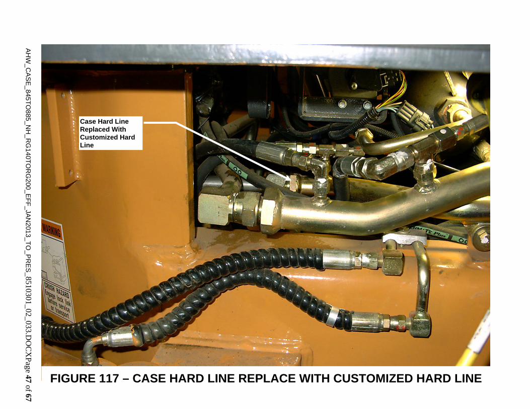
Case Hard Line Replaced With Customized Hard Line
FIGURE 117 – CASE HARD LINE REPLACE WITH CUSTOMIZED HARD LINE

AH
W_C
AS
E_845T
O885_N
H_R
G140T
OR
G200_E
FF
_JAN
2013_TO
_PR
ES
_8510301_02_033.DO
CX
Page 48 of 67
Henke Return Hose 7110636
FIGURE 118 – ATTACHMENT OF HENKE RETURN HOSE TO CASE TANK
AHW_CASE_845TO885_NH_RG140TORG200_EFF_JAN2013_TO_PRES_8510301_02_033.DOCXPage 49 of 67
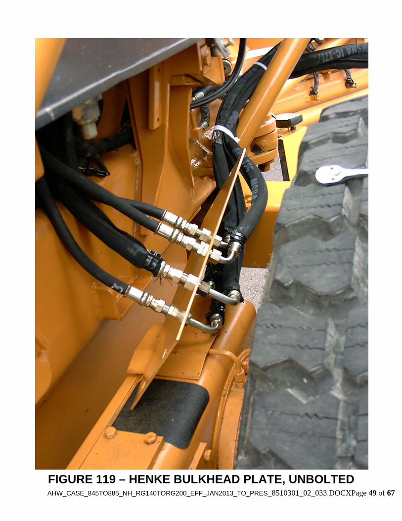
FIGURE 119 – HENKE BULKHEAD PLATE, UNBOLTED

AH
W_C
AS
E_845T
O885_N
H_R
G140T
OR
G200_E
FF
_JAN
2013_TO
_PR
ES
_8510301_02_033.DO
CX
Page 50 of 67
FIGURE 120 – HENKE BULKHEAD PLATE, INSTALLED
AHW_CASE_845TO885_NH_RG140TORG200_EFF_JAN2013_TO_PRES_8510301_02_033.DOCXPage 51 of 67
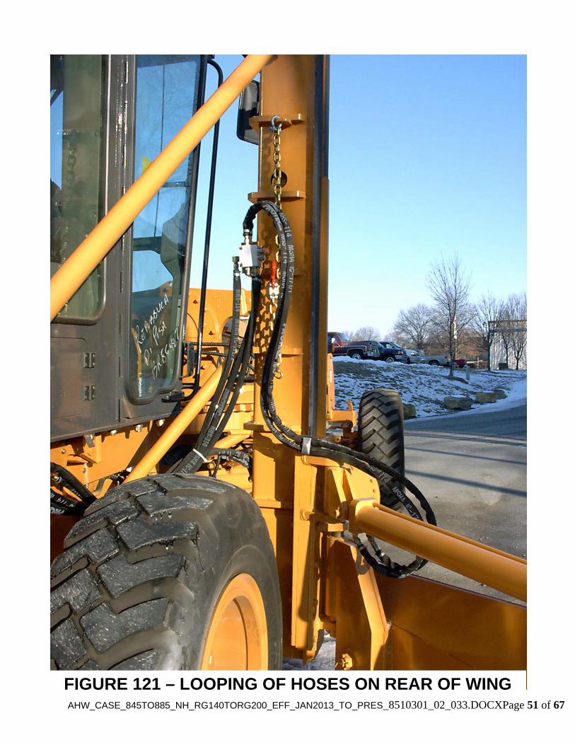
FIGURE 121 – LOOPING OF HOSES ON REAR OF WING

AHW_CASE_845TO885_NH_RG140TORG200_EFF_JAN2013_TO_PRES_8510301_02_033.DOCXPage 52 of 67
42”
FIGURE 122 – ATTACHMENT OF HOSES TO CLAMP ON WING SLIDE ASSEMBLY

AHW_CASE_845TO885_NH_RG140TORG200_EFF_JAN2013_TO_PRES_8510301_02_033.DOCXPage 53 of 67
6. Mounting Instructions for Henke All-Hydraulic Wing on Case & New Holland Graders
6.1 Ladder Removal 1. Remove the ladder on the side where the wing will be mounted. The ladder can not be used when the wing is installed. The ladder should be re-installed if the wing is removed.
6.2 Installation of Weld-On Mounting Plate Under Grader
Notes: (a) Before welding, disconnect electrical system components as directed in the Case grader manual. (b) Refer to Figures 1, 7, & 101. 1. Remove paint from the bottom of the grader to provide a clean welding surface at least 3/4" in
each direction from the corner of all weld joints. Also ensure that the mounting plate itself is clean and free of mill scale at least 3/4" in each direction from the corner of all weld joints.
2. Position the mounting plate as shown in Figure 7. Ensure that it is tight against the bottom of
the grader. Weld the frame ready plate securely in place as shown in Figure 7. The two plug weld holes should be welded first to prevent warping of the plate. Also note that no weld is required on the rear side of the plate. Allow to cool fully.
6.3 Mounting of Pipe Brace Ears on Grader Frame
Note: Refer to Figures 1, 102, & 103. 1. Position the front pipe brace ear assembly (249-0598) on the side of the grader frame as
shown in Figure 102. Mark its position, then remove the paint from the grader frame at least 1/2" in each direction. Cover the area under the pipe brace ear to avoid weld spatter damaging the paint or grader components. Weld the front pipe brace ear in place using min. 5/16" fillet welds all around.
2. Position the rear pipe brace ear assembly (249-0619) on the side of the grader frame as shown
in Figure 103. Mark its position, then remove paint from the grader neck at least 1/2" in each direction. Weld the rear pipe brace assembly in place using min. 5/16" fillet welds all around.
3. Prime and paint pipe brace ears and surrounding area to match grader. 6.4 Installation of Attaching Structure and Wing Post 1. Using a fork truck or other secure method, lift the 249-0590 attaching structure (Item 13,
Figure 1) into position under the grader. Fasten to grader using (12) 3/4-10 x 3.5" Gr. 8

AHW_CASE_845TO885_NH_RG140TORG200_EFF_JAN2013_TO_PRES_8510301_02_033.DOCXPage 54 of 67
bolts, (12) 3/4-10 Gr. 8 nuts, and (24) 3/4" heat treated washers. Starting at the center and working outward, torque all (12) 3/4" nuts per Table 13.
2. Securely install a chain or strap through the two large holes at the top of the post assembly
(Item 12, Figure 1). Raise the post into position. Fasten post to attaching structure using (8) 1-8 x 4 Gr. 8 bolts, (8) 1-8 Gr. 8 nuts, and (16) 1” heat treated washers. Starting at the center and working outward, torque all (12) 1” nuts per Table 13.
3. Prime and paint weld-on mounting plate and surrounding area to match grader. 6.5 Installation of Pipe Braces on Wing Post Note: Refer to Figures 1 and 102 thru 105 1. Front pipe brace: Install (1) 7070042 ball joint (2” diameter ball) on bottom of the lower
pipe brace ear on the post, and one on top of the front pipe brace ear assembly on the grader. Secure with (1) 3/4-10 x 3.25" Gr. 8 bolt, (1) 3/4-10 nut, and (1) 3/4” lock washer per ball joint. Tighten finger-tight only.
2. Rear pipe brace: Install (1) 7070043 ball joint (2.5” diameter ball) on bottom of the upper
pipe brace ear on the post, and one on front of the rear pipe brace ear assembly on the grader. Secure with (1) 3/4-10 x 3.25" Gr. 8 bolt, (1) 3/4-10 nut, and (1) 3/4” lock washer per ball joint. Tighten finger-tight only.
3. Orient each pair of ball joints so that a straight line is formed (as much as possible) between
the bolts, ball joints, and pipe (bolt-ball joint-pipe-ball joint-bolt all in a straight line). Tighten each ball joint slightly, but do not fully torque.
4. Test fit each pipe brace between one pair of ball joints. Trim each pipe brace as necessary to
obtain a snug fit, but be careful not to trim too much. When pipe braces have been trimmed properly, install between ball joints. Double check straightness of bolts, ball joints, and pipe, then tack weld ball joints to pipe on both ends. Remove pipe/ball joint assemblies and fully weld ball joints to pipe using minimum 1/4" fillet welds all around. Prime and paint each assembly and allow to dry. Re-install pipe brace assemblies, and fully torque all (5) nuts per Table 13.
Note: All wings will be supplied with one of the following options: elevating rear, fixed rear, or rear ripper attachment. Determine which option your wing was supplied with and proceed to the correct section -- 6.6, 6.7, or 6.8. 6.6 Installation of Optional Elevating Rear Assembly Note: Refer to Figures 106 & 107. 1. Remove the (2) Case tie-down plates bolted to the rear of the grader.
AHW_CASE_845TO885_NH_RG140TORG200_EFF_JAN2013_TO_PRES_8510301_02_033.DOCXPage 55 of 67
2. Lift the elevating rear into position, then fasten to grader using the same hardware that was removed in the previous step. Fully torque per Table 13.
6.7 Installation of Optional Fixed Rear Assembly Note: Refer to Fig. 108. 1. Remove the (2) Case tie-down plates bolted to the rear of the grader. 2. Lift the fixed rear into position, then fasten to grader using the same hardware that was
removed in the previous step. Fully torque per Table 13. 6.8 Installation of Optional Rear Ripper Attachment Note: Refer to Figures 4 & 109. 1. The rear ripper attachment will be welded to the right hand side of the grader’s rear ripper. If the grader does not have a rear ripper, then a different type of rear assembly option must be used. 2. Mark the location at which the rear ripper ear weldment (Item 1, Figure 4) will be welded to the rear ripper. It should be approximately centered on the end of the rear ripper. Remove the paint from the Case/New Holland rear ripper and the Henke ear weldment at least 1/2” in every direction from the corners of the weld joints. 3. Weld the Henke ear weldment to the right side of the Case/New Holland rear ripper using minimum 3/8” fillet welds all around. 6.9 Mounting of Henke Control Valve Note: Refer to Figures 110 & 111. 1. Attach valve to 279-0474 valve bracket assembly using (3) 5/16-18 x 3 bolts and (3) nylock nuts. 2. Attach valve bracket assembly to top side of 2400-1061 weld-on mounting plate (Item 17, Fig. 1) using (4) 5/8-11 x 3.5 bolts, (8) flat washers, and (8) toplock nuts. 6.10 Installation of Auxiliary Controls in Grader Cab Note: Refer to Figures 112 & 113 & Tables 7 thru 9. 1. Attach 2700-1278 handles to 279-0503 bracket assembly using (3) 5/16-18 bolts (4.5” length for 2 handles, 6” length for 3 handles) and (3) nylock nuts. 2. Attach this assembly to the R/H vertical handle bar in the cab using (2) 7090558 clamp pairs, (1) 7090559 cover plate, and (4) 3/8-16 x 2.25” bolts. The bottom of the bracket should be

AHW_CASE_845TO885_NH_RG140TORG200_EFF_JAN2013_TO_PRES_8510301_02_033.DOCXPage 56 of 67
located 23” from the cab floor. Adjust the handle position so it is comfortable and does not interfere with any other controls, then fully tighten. 6.11 Drilling of Hole in Cab Floor and Installation of Control Cables Note: Refer to Figures 112 & 113, and Tables 7 thru 9. 1. Pull the rubber mat up out of the way. Remove R/H outer trim piece. 2. Mark the correct hole center in the cab floor per Figure 112. Verify before drilling that there is nothing below the cab in the way, including structural members. 3. Drill (1) 1.25” hole through the cab floor. Replace the outer trim piece and rubber mat and cut two small (approx. 3/4 to 1” long) slits in the rubber mat directly above the 1.25” hole in the cab floor, to allow for the control cables to pass through. 4. Attach the first 7080502 control cable to the appropriate workport section of the auxiliary valve. On valves with three or more workports, cables should always be attached to the centermost workports first, then the other end of the cable should be attached to the appropriate control handle, and all adjustments completed, before installing the next cable. One 7080119 RVC (Remote Valve Control) hookup kit is required for each valve section. The valve generally comes with a bracket attached to each workport for manual control handle installation. Remove this bracket and discard, but be careful to retain and re-install both washers which are underneath this bracket when it is removed. Refer to instructions provided with RVC kit for additional information on RVC kit installation. It is important that the RVC kit be adjusted correctly at the valve to ensure that the full range of motion of the valve spool can be obtained using the control handle. 5. Run the first control cable up through the hole in the cab floor. Attach the threaded end of the cable to the appropriate control handle (generally, wing slide is furthest inboard, then wing lift, then elevating rear if applicable). Before proceeding, check to see that each handle travels the same distance forward as it does backward from the neutral position. If it does not, adjust the RVC kit at the valve until equal travel is obtained (indicating full valve spool travel). 6. Repeat steps 4 and 5 until all control cables are installed, and all adjustments completed. 6.12 Tie-In of Henke Valve to Grader Hydraulic System Caution: The grader must remain turned off when working on the hydraulics . Notes: (a) Refer to Figs. 8, 9, 110, 111, 114 thru 118, and Tables 7 thru 10. (b) All required hoses and fittings are included in Henke tie-in kit 7080465, and in the appropriate valve & controls kit, except as noted. (c) All Henke hoses have the hose part number engraved on the outside of the hose ferrule on one end.

AHW_CASE_845TO885_NH_RG140TORG200_EFF_JAN2013_TO_PRES_8510301_02_033.DOCXPage 57 of 67
1. LOAD SENSE: Install all three adapters in 7080340 load sense shuttle valve per Figure 9, and fully tighten before proceeding. Install load sense shuttle valve as shown in Figures 8, 9, 114, & 115. 2. PRESSURE: Remove existing hard pressure line running from L/H forward side of Case valve (see Figures 116 & 117), and replace with Henke part 7090551 (same part with additional -8 JIC male fitting added). Run pressure hose to Henke valve port “P” (see Figure 110). 3. RETURN: Install fittings in Henke valve port “T” (see Figure 110). Two return hoses are required: one runs to Henke bulkhead position 5 (see Section 6.13 & Figure 119; this hose is in kit 7080464), and one tees into the Case hydraulic tank (see Figure 118). To avoid excessive oil spillage, do not take the final step of teeing in to the Case hydraulic tank until all fittings and hoses on the return circuit are installed and fully tightened (see Section 6.14, Step 5). 6.13 Plumbing of Hoses from Henke Valve to Henke Bulkhead Plate Notes: (a) Refer to Figs. 8, 10, 110, 111, & 119; and Table 11. (b) All required hoses and fittings are included in Henke kit 7080464. 1. Remove Case cover and install Henke bulkhead plate 2700-1225 in its place. See Figure 119. 2. Install all (5) 7090443 bulkhead fittings in bulkhead plate and fully tighten. 3. Run all hoses from Henke valve to bulkhead plate per Figure 8. 6.14 Plumbing of Hoses from Bulkhead Plate to Slide Cylinder and Mudroc Valve Notes: (a) Refer to Figures 10, 11, 104, 105, 120, 121, and Table 11.
(b) All required hoses, fittings, etc. are included in Henke Kit No. 7080464 1. Install Mudroc relief valve on wing post, referring to Figure 11. Install (1) 7090117 elbow in
Mudroc port T and (4) 7090290 adapters in Mudroc ports C1, C2, V1, and V2. Install (2) 7090009 –8 JIC caps on the 7090290 adapters in ports C1 and C2 and fully tighten. Install Mudroc valve on post using (2) 5/16-18 x 4 bolts and (2) 5/16-18 nylock nuts (supplied with Mudroc valve). Fully tighten fasteners.
2. Run hoses to slide cylinder: Using a cloth, clean area around slide cylinder ports at base of
wing post. Remove plugs. Install (2) 7090014 adapters in cylinder ports and fully tighten. Feed one end of (2) 7110631 hoses down through cutout on inboard side of post and connect to ports on slide cylinder base. Connect these hoses to the appropriate positions on the bulkhead plate.
3. Run wing lift cylinder hoses to Mudroc valve: Run (2) 710632 hoses from Mudroc valve
ports V1 & V2 to appropriate positions on the bulkhead plate.
AHW_CASE_845TO885_NH_RG140TORG200_EFF_JAN2013_TO_PRES_8510301_02_033.DOCXPage 58 of 67
4. Run Mudroc return hose: Connect one end of 7110633 hose to 7090117 fitting on Mudroc port T. Connect other end to bulkhead position 5.
5. Complete the teeing in of the return line to the Case tank fitting. Conduct a leak check on all
hydraulics installed so far. Tighten fittings as necessary. 6. Install 2700-1225 bulkhead plate on Case grader, using Case bolts removed earlier, and fully
tighten. 7. Tie all hoses running from bulkhead plate to wing together with (2) large cable ties supplied
(see Figure 120). 6.15 Plumbing of Hoses to Optional Elevating Rear (if applicable) Note: Refer to Figures 8, 106, 107, & 111; and Table 12. 1. Install hydraulic fittings in Henke valve and elevating rear cylinder. Run hoses from Henke
valve to elevating rear cylinder. Note on Figure 107 how hoses are routed. Install spiral hose wrap around both hoses – 22” piece forward of hose clamp, 16” piece aft of hose clamp (see Figure 107). Tighten all fittings.
6.16 Mounting Instructions for Moldboard and Pushbeam Assemblies Note: Refer to Figure 2 & Table 3. 1. Remove the attaching bolt, bushing, nut, washers, and cotter pin (Items 67, 56, 68 (qty. 2),
69, and 70; Figure 2) from the moldboard assembly. These are the parts which will be used to attach the moldboard (Item 51, Figure 2) to the 249-0192 hinge assembly (Item 50, Figures 1 & 2).
2. Install the attaching bolt, one washer, and bushing through the moldboard as shown in Figure
2. 3. Lift moldboard using lift loop. Use auxiliary controls to raise 249-0192 hinge assembly until
it is at the correct height to pin up with the moldboard. Install bushing through banjo hinge assembly, and secure with washer, nut, and cotter pin. Make sure nut is tightened fully against bushing before installing cotter pin.
4. Attach the outer tube portion of the pushbeam (Item 72, Fig. 2) to the 249-0193
pushbeam/moldboard joint (Item 71, Figure 2) using the supplied hardware (Items 78 and 79, Figure 2).
5. Attach the inner tube portion of the pushbeam (Item 73, Fig. 2) to the rear assembly using (1)
1/2-13 x 4 Gr. 2 bolt (7020279), (2) 1/2” flat washers (7040005) and (1) 1/2-13 toplock nut (7030031). CAUTION - THIS IS A SHEAR BOLT AND SERVES AS A SAFETY DEVICE. DO NOT REPLACE WITH A HIGHER GRADE BOLT!
AHW_CASE_845TO885_NH_RG140TORG200_EFF_JAN2013_TO_PRES_8510301_02_033.DOCXPage 59 of 67
6. Attach the moldboard lift cylinder to the 249-0185 knuckle assembly (Item 52, Figures 1 & 2) using the appropriate hardware called out in Fig. 1.
NOTE: The ports on the lift cylinder MUST be facing down when the cylinder is installed. Rotate if required (it is not necessary to unpin the barrel end of the cylinder to rotate the rod).
6.17 Plumbing of Hydraulics to Moldboard Lift Cylinder Notes: (a) Note: Refer to Figures 10, 104, 105, 120, 121, & 122; and Table 11. (b) All required hoses, fittings, etc. are included in Henke Kit No. 7080464. 1. Remove (2) caps from the adapters in ports C1 & C2 of the Mudroc valve. Attach one end of
(2) 710605 hoses to adapters in ports C1 and C2. Attach hoses to clamp base on wing slide, leaving 42” of each hose outboard of the clamp (see Fig. 102). Attach other end of each hose to 7090283 adapters installed in ports of moldboard lift cylinder, ensuring that each hose is run to the proper port. Tighten all fittings, with the two hoses near but not touching the wing lift cylinder.
2. Check function of moldboard lift cylinder. It should be <Pull Back On Handle> = <Wing
Lifts Up>. If it is incorrect, reverse the hoses to correct.
CAUTION: Retracting the moldboard lift cylinder will cause the wing to retract into "transport position" against the grader. Be certain that no personnel are near the path of the wing. Make sure that all tools and other objects have been removed from the area.
WARNING: Do not articulate the grader, or raise or lower the elevating rear or rear ripper, until the Mudroc valve is properly adjusted! Doing so can cause damage to the wing lift cylinder and other components. 3. Conduct a hydraulic leak check on the moldboard lift cylinder circuit. Tighten fittings as
necessary.
6.18 Adjustment of Mudroc Valve & Functional Check 1. Adjust Mudroc valve per instructions on Figure 12. CAUTION: Failure to properly adjust the Mudroc valve to proper relief pressures may result in damage to wing components. 2. Test all functions of wing and other components through their full range of motion to ensure
that there are no apparent problems. Ensure that wing lift cylinder relieves pressure effectively in the following two cases: (a) with wing in transport position, articulate grader and/or raise or lower rear; and (b) with wing in plowing position, attempt to apply down pressure at outboard edge of cutting edge to lift grader. Re-adjust Mudroc valve if necessary to obtain proper relief function.
6.19 Paint Touch-Up

AHW_CASE_845TO885_NH_RG140TORG200_EFF_JAN2013_TO_PRES_8510301_02_033.DOCXPage 60 of 67
1. Wipe down grader and wing components with appropriate cleaning solvent as necessary to
remove dirt, hydraulic fluid, etc. 2. Touch up any damaged areas in the paint job.
6.20 Final Wrap-Up 1. Install simplified safety chain assembly on wing post. Remove 7/16" clevis from one end of
safety chain. Pass clevis through ear on rear side of post (on the second rib down from the top of the post). Install pin through chain and secure with cotter pin. Attach hook on other end of chain in one of two places: (a) Hook through lift ear on wing moldboard (to prevent wing from drifting out when is in transport position), or (b) Hook through large hole in 4th rib down from top of post for storage when not in use.
2. Top off hydraulic fluid in main hydraulic tank using the fluid specified in the Case Grader Operation & Maintenance Manual.
3. Apply the supplied decals, if not already installed, on Henke Plow and Attach Items as shown
in the Decals section of this book.

AHW_CASE_845TO885_NH_RG140TORG200_EFF_JAN2013_TO_PRES_8510301_02_033.DOCXPage 61 of 67
<THIS PAGE IS INTENTIONALLY LEFT BLANK>

AHW_CASE_845TO885_NH_RG140TORG200_EFF_JAN2013_TO_PRES_8510301_02_033.DOCXPage 62 of 67
Bolt Size (in.) Grade 2 Bolts Grade 5 Bolts Grade 8 Bolts
1/4-20 4 6 85/16-18 7 11 133/8-16 11 17 241/2-13 28 44 555/8-11 50 84 1103/4-10 95 150 1857/8-9 140 220 2701-8 205 330 430DO NOT USE THIS TABLE FOR NON-LOCKING NUTS
Bolt Size (in.) Grade 2 Bolts Grade 5 Bolts Grade 8 Bolts
1/4-20 5.5 9 12.55/16-18 11 18 263/8-16 20 33 461/2-13 50 80 1155/8-11 100 160 2253/4-10 175 280 4007/8-9 175 450 6501-8 270 675 975
DO NOT USE THIS TABLE FOR LOCKING NUTS
TABLE 14 – Dry Torque Values (Ft.-Lbs.) for Standard Non-Locking Nuts ONLY (See Page Notes)
TABLE 13 – Dry Torque Values (Ft.-Lbs.) - for Toplock (All-Metal) or Nylock Nuts ONLY (See Page Notes)
Page Notes:
1. “Dry” means plain or zinc-plated fasteners without any lubrication.
2. Fastener Grade Identification: a. Grade 8 bolts are identified by having (6) radial marks on the top of the bolt head.
Grade 8 nuts are identified by having radial marks on (2) adjacent corners.
b. Grade 5 bolts are identified by having (3) radial marks on the top of the bolt head. Grade 5 nuts are identified by having radial marks on (2) NON-adjacent corners.
c. Grade 2 bolts and nuts are identified by having (0) radial marks.
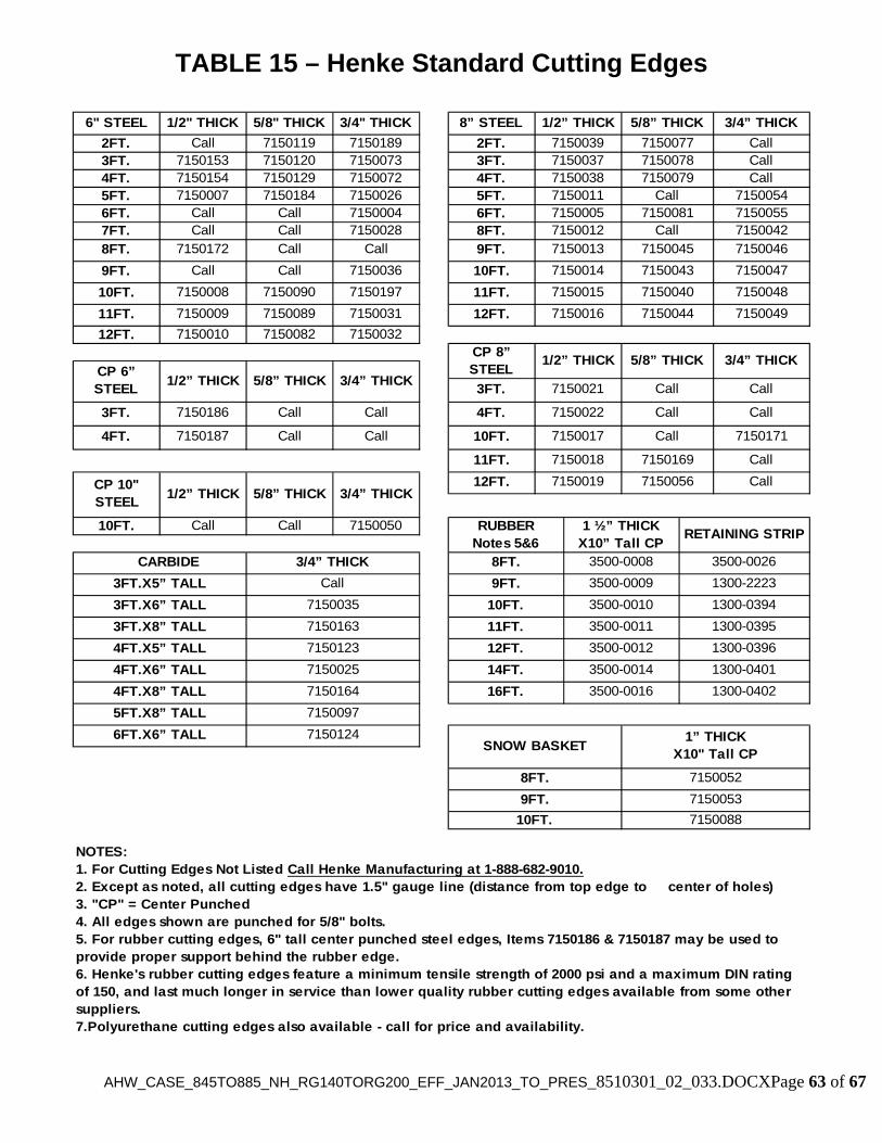
AHW_CASE_845TO885_NH_RG140TORG200_EFF_JAN2013_TO_PRES_8510301_02_033.DOCXPage 63 of 67
TABLE 15 – Henke Standard Cutting Edges
10FT. 7150088
SNOW BASKET1” THICK
X10" Tall CP
16FT. 3500-0016 1300-0402
12FT. 3500-0012 1300-0396
RUBBERNotes 5&6
1 ½” THICK X10” Tall CP
RETAINING STRIP
CARBIDE 3/4” THICK
4FT.X5” TALL 7150123
4FT.X8” TALL 7150164
8FT. 3500-0008 3500-0026
9FT. 7150053
CP 8” STEEL
1/2” THICK 5/8” THICK 3/4” THICK
12FT. 7150019 7150056 Call
9FT. 7150013 7150045 71500468FT. 7150172 Call Call
11FT. 3500-0011 1300-03953FT.X8” TALL 7150163
10FT. 3500-0010
Call
8FT.
6FT.X6” TALL 7150124
14FT. 3500-0014 1300-04014FT.X6” TALL 7150025
7150052
1300-03943FT.X6” TALL 7150035
10FT. Call Call 7150050
3FT.X5” TALL Call 9FT. 3500-0009 1300-2223
CP 10"STEEL
1/2” THICK 5/8” THICK 3/4” THICK
7150169 Call
4FT. 7150187 Call Call
11FT. 7150018
3FT. 7150186 Call Call
10FT. 7150017 Call 7150171
CP 6” STEEL
1/2” THICK 5/8” THICK 3/4” THICK3FT. 7150021 Call
4FT. 7150022 Call Call
7150044 7150049
12FT. 7150010 7150082 7150032
12FT. 715001611FT. 7150009 7150089 7150031
7150043 7150047
10FT. 7150008 7150090 7150197 11FT. 7150015 7150040 7150048
9FT. Call Call 7150036 10FT. 7150014
7150081 71500557FT. Call Call 7150028 8FT. 7150012 Call 71500426FT. Call Call 7150004 6FT. 7150005
3FT. 7150037 7150078 Call7150079 Call
5FT. 7150007 7150184 7150026 5FT. 7150011 Call 71500544FT. 7150154 7150129 7150072 4FT. 7150038
NOTES:1. For Cutting Edges Not Listed Call Henke Manufacturing at 1-888-682-9010.2. Except as noted, all cutting edges have 1.5" gauge line (distance from top edge to center of holes)3. "CP" = Center Punched4. All edges shown are punched for 5/8" bolts.5. For rubber cutting edges, 6" tall center punched steel edges, Items 7150186 & 7150187 may be used to provide proper support behind the rubber edge.6. Henke's rubber cutting edges feature a minimum tensile strength of 2000 psi and a maximum DIN rating of 150, and last much longer in service than lower quality rubber cutting edges available from some other suppliers.7.Polyurethane cutting edges also available - call for price and availability.
5FT.X8” TALL 7150097
1/2” THICK 5/8” THICK 3/4” THICK
2FT. Call 7150119 7150189 2FT. 7150039 7150077
6" STEEL 1/2" THICK 5/8" THICK 3/4" THICK 8” STEEL
Call3FT. 7150153 7150120 7150073

AHW_CASE_845TO885_NH_RG140TORG200_EFF_JAN2013_TO_PRES_8510301_02_033.DOCXPage 64 of 67
TABLE 16 – Henke Standard Cutting Edge Hardware
TYPE LENGTH PART NO. USES/NOTES
2” 71500012 ½” 7150003
3” 71500023 ½” 7150103
4” 71501054 ½” 7150106
5” 7150108
6” 7150107
3” 70202804” 70202875” 7020359
6” 7020363
4” 70200644 ½” 7020128
5” 7020295
NYLOCK NUT5/8-11 GRADE 8
N/A 7030095USE WITH RUBBER OR POLY CUTTING EDGES
TOPLOCK NUT 5/8-11 GRADE C
N/A 7030084USE WITH STEEL OR
CARBIDE CUTTING EDGES
PLOWBOLTS 5/8-11 GRADE 8
FOR STANDARD CUTTING EDGES AND WEAR
GUARDS
CARRIAGE BOLTS
5/8-11 GRADE 8
FOR SOME WRAPAROUND CURB GUARDS
(SQUARE HOLES, NOT COUNTER SUNK)
HEX BOLTSRUBBER AND POLY
CUTTING EDGES (USE NYLOCK NUTS ONLY)
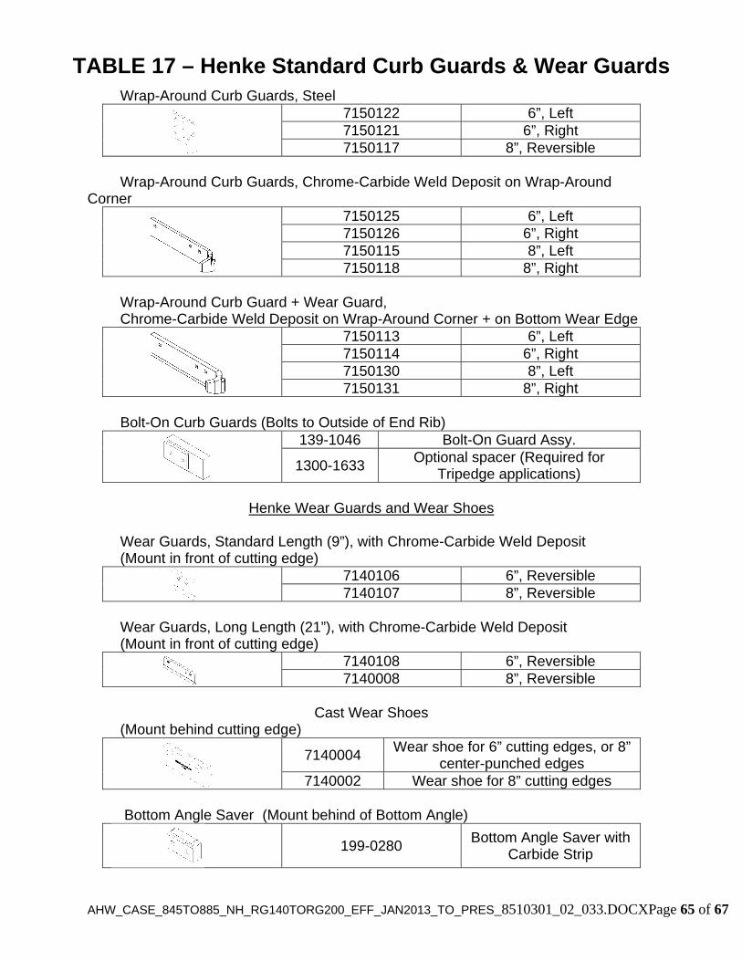
AHW_CASE_845TO885_NH_RG140TORG200_EFF_JAN2013_TO_PRES_8510301_02_033.DOCXPage 65 of 67
Wrap-Around Curb Guards, Steel 7150122 6”, Left
7150121 6”, Right 7150117 8”, Reversible
Wrap-Around Curb Guards, Chrome-Carbide Weld Deposit on Wrap-Around Corner
7150125 6”, Left 7150126 6”, Right 7150115 8”, Left 7150118 8”, Right
Wrap-Around Curb Guard + Wear Guard, Chrome-Carbide Weld Deposit on Wrap-Around Corner + on Bottom Wear Edge
7150113 6”, Left 7150114 6”, Right 7150130 8”, Left 7150131 8”, Right
Bolt-On Curb Guards (Bolts to Outside of End Rib)
139-1046 Bolt-On Guard Assy.
1300-1633 Optional spacer (Required for
Tripedge applications)
Henke Wear Guards and Wear Shoes Wear Guards, Standard Length (9”), with Chrome-Carbide Weld Deposit (Mount in front of cutting edge)
7140106 6”, Reversible 7140107 8”, Reversible
Wear Guards, Long Length (21”), with Chrome-Carbide Weld Deposit (Mount in front of cutting edge)
7140108 6”, Reversible 7140008 8”, Reversible
Cast Wear Shoes
(Mount behind cutting edge) 7140004
Wear shoe for 6” cutting edges, or 8” center-punched edges
7140002 Wear shoe for 8” cutting edges Bottom Angle Saver (Mount behind of Bottom Angle)
199-0280
Bottom Angle Saver with Carbide Strip
TABLE 17 – Henke Standard Curb Guards & Wear Guards

<THIS PAGE IS INTENTIONALLY LEFT BLANK>
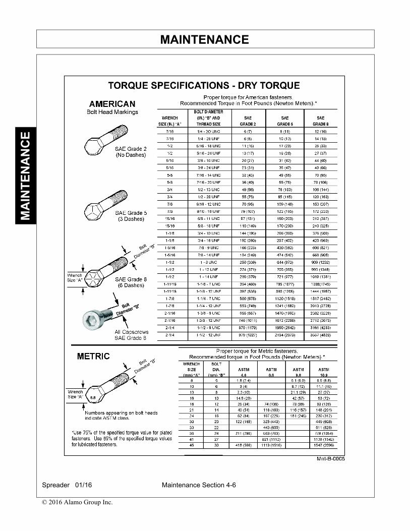
MAINTENANCE
Spreader 01/16 Maintenance Section 4-6
© 2016 Alamo Group Inc.
MA
INT
EN
AN
CE
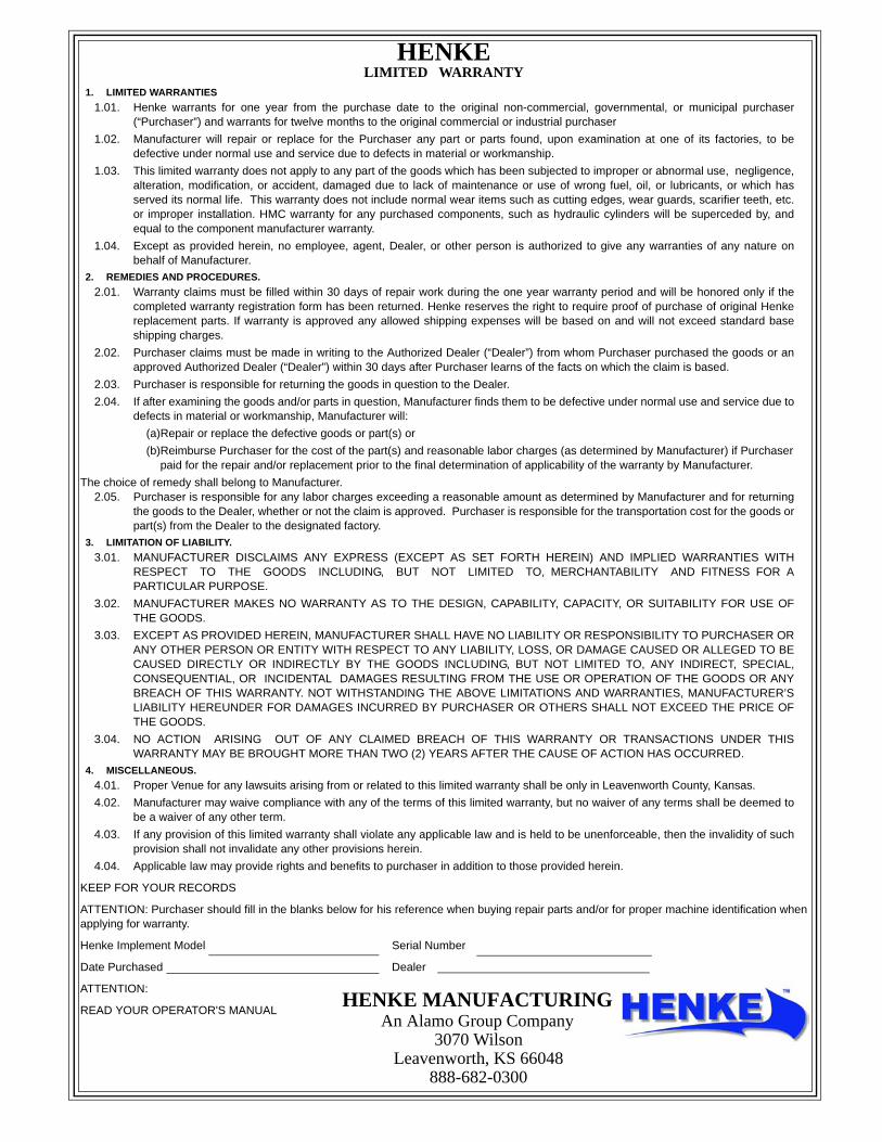
HENKE LIMITED WARRANTY
1. LIMITED WARRANTIES
1.01. Henke warrants for one year from the purchase date to the original non-commercial, governmental, or municipal purchaser(“Purchaser”) and warrants for twelve months to the original commercial or industrial purchaser
1.02. Manufacturer will repair or replace for the Purchaser any part or parts found, upon examination at one of its factories, to bedefective under normal use and service due to defects in material or workmanship.
1.03. This limited warranty does not apply to any part of the goods which has been subjected to improper or abnormal use, negligence,alteration, modification, or accident, damaged due to lack of maintenance or use of wrong fuel, oil, or lubricants, or which hasserved its normal life. This warranty does not include normal wear items such as cutting edges, wear guards, scarifier teeth, etc.or improper installation. HMC warranty for any purchased components, such as hydraulic cylinders will be superceded by, andequal to the component manufacturer warranty.
1.04. Except as provided herein, no employee, agent, Dealer, or other person is authorized to give any warranties of any nature onbehalf of Manufacturer.
2. REMEDIES AND PROCEDURES.
2.01. Warranty claims must be filled within 30 days of repair work during the one year warranty period and will be honored only if thecompleted warranty registration form has been returned. Henke reserves the right to require proof of purchase of original Henkereplacement parts. If warranty is approved any allowed shipping expenses will be based on and will not exceed standard baseshipping charges.
2.02. Purchaser claims must be made in writing to the Authorized Dealer (“Dealer”) from whom Purchaser purchased the goods or anapproved Authorized Dealer (“Dealer”) within 30 days after Purchaser learns of the facts on which the claim is based.
2.03. Purchaser is responsible for returning the goods in question to the Dealer.
2.04. If after examining the goods and/or parts in question, Manufacturer finds them to be defective under normal use and service due todefects in material or workmanship, Manufacturer will:
(a)Repair or replace the defective goods or part(s) or
(b)Reimburse Purchaser for the cost of the part(s) and reasonable labor charges (as determined by Manufacturer) if Purchaserpaid for the repair and/or replacement prior to the final determination of applicability of the warranty by Manufacturer.
The choice of remedy shall belong to Manufacturer.2.05. Purchaser is responsible for any labor charges exceeding a reasonable amount as determined by Manufacturer and for returning
the goods to the Dealer, whether or not the claim is approved. Purchaser is responsible for the transportation cost for the goods orpart(s) from the Dealer to the designated factory.
3. LIMITATION OF LIABILITY.
3.01. MANUFACTURER DISCLAIMS ANY EXPRESS (EXCEPT AS SET FORTH HEREIN) AND IMPLIED WARRANTIES WITHRESPECT TO THE GOODS INCLUDING, BUT NOT LIMITED TO, MERCHANTABILITY AND FITNESS FOR APARTICULAR PURPOSE.
3.02. MANUFACTURER MAKES NO WARRANTY AS TO THE DESIGN, CAPABILITY, CAPACITY, OR SUITABILITY FOR USE OFTHE GOODS.
3.03. EXCEPT AS PROVIDED HEREIN, MANUFACTURER SHALL HAVE NO LIABILITY OR RESPONSIBILITY TO PURCHASER ORANY OTHER PERSON OR ENTITY WITH RESPECT TO ANY LIABILITY, LOSS, OR DAMAGE CAUSED OR ALLEGED TO BECAUSED DIRECTLY OR INDIRECTLY BY THE GOODS INCLUDING, BUT NOT LIMITED TO, ANY INDIRECT, SPECIAL,CONSEQUENTIAL, OR INCIDENTAL DAMAGES RESULTING FROM THE USE OR OPERATION OF THE GOODS OR ANYBREACH OF THIS WARRANTY. NOT WITHSTANDING THE ABOVE LIMITATIONS AND WARRANTIES, MANUFACTURER’SLIABILITY HEREUNDER FOR DAMAGES INCURRED BY PURCHASER OR OTHERS SHALL NOT EXCEED THE PRICE OFTHE GOODS.
3.04. NO ACTION ARISING OUT OF ANY CLAIMED BREACH OF THIS WARRANTY OR TRANSACTIONS UNDER THISWARRANTY MAY BE BROUGHT MORE THAN TWO (2) YEARS AFTER THE CAUSE OF ACTION HAS OCCURRED.
4. MISCELLANEOUS.
4.01. Proper Venue for any lawsuits arising from or related to this limited warranty shall be only in Leavenworth County, Kansas.
4.02. Manufacturer may waive compliance with any of the terms of this limited warranty, but no waiver of any terms shall be deemed tobe a waiver of any other term.
4.03. If any provision of this limited warranty shall violate any applicable law and is held to be unenforceable, then the invalidity of suchprovision shall not invalidate any other provisions herein.
4.04. Applicable law may provide rights and benefits to purchaser in addition to those provided herein.
KEEP FOR YOUR RECORDS
ATTENTION: Purchaser should fill in the blanks below for his reference when buying repair parts and/or for proper machine identification whenapplying for warranty.
Henke Implement Model Serial Number
Date Purchased Dealer
ATTENTION:
READ YOUR OPERATOR'S MANUALHENKE MANUFACTURING
An Alamo Group Company3070 Wilson
Leavenworth, KS 66048888-682-0300

AHW_CASE_845TO885_NH_RG140TORG200_EFF_JAN2013_TO_PRES_8510301_02_033.DOCXPage 67 of 67
For units delivered within the past 12 months, report any warranty problems
needing repair to our Product support department. Please have information ready
regarding:
1. Henke unit model and serial number, 2. Model of equipment Henke unit is attached to (prime mover) 3. Description of the problem and any helpful information by
the end user. (Photos are always helpful). Measurements or photos may be requested by Henke engineering for any issues regarding prime mover proximity and clearance, or any other unique considerations of fit and adaptability. These may be necessary for a proper repair recommendation and procedure. Henke will respond with a written labor hour allowance for Henke participation on a faxed claim form and will ship any required replacement parts. If necessary, a repair procedure will be included on the claim form. A parts invoice will be generated to confirm shipment of the replacement parts. If defective parts are needed for analysis, Henke will request their return.
Any such returned items are to be labeled with the claim number and returned to: Henke Manufacturing Corp. ATTN: Product Support 3070 Wilson Ave. Leavenworth, KS. 66048 RGA#_____________
The dealer should perform repairs as agreed on a dealer warranty repair order. Return the claim form with a copy of the dealer warranty repair order and service report. Credit as agreed will be issued to the dealer upon receipt of the dealer warranty repair order invoice (Pro-forma invoice), and upon receipt, inspection and warranty confirmation of the returned parts if any. Parts & Service Assistance Parts and service assistance is available, Monday through Friday, from 8:00 am to 5:00 pm, CST. Call 913-682-9000. Our web site, www.henkemfg.com, is a quick source for parts pricing, and many common parts diagrams. Parts purchase orders may be faxed in at any time to 913-682-0300. Faxed orders are encouraged, as they help insure order accuracy and follow up. Include any special instructions, such as drop ship addresses on your order.
Dealer Warranty Procedure