Hei report
58
Communication 16 HEALTH EFFECTS INSTITUTE FEBRUARY 2011 HEI Special Committee on Emerging Technologies The Future of Vehicle Fuels and Technologies: Anticipating Health Benefits and Challenges
-
date post
13-Sep-2014 -
Category
Documents
-
view
1.633 -
download
0
description
Transcript of Hei report

101 Federal Street
Boston, MA 02110-1817, USA
Phone +1-617-488-2300
Fax +1-617-488-2335
www.healtheffects.org
COMMUNICATION 13October 2008
H E A L T HE F F E CTSINSTITUTE
Communication 16H E A L T H E F F E C T S I N S T I T U T E
F E B R U A R Y 2 0 1 1
HEI Special Committee on Emerging Technologies
The Future of Vehicle Fuels and Technologies: Anticipating Health Benefi ts and Challenges


The Future of Vehicle Fuels and Technologies: Anticipating Health
Benefits and Challenges
HEI Special Committee on Emerging Technologies
Communication 16
Health Effects Institute
Boston, Massachusetts
Trusted Science
·
Cleaner Air
·
Better Health

Publishing history: The Web version of this document was posted at
www.healtheffects.org
in February 2011.
Citation for document:
HEI Special Committee on Emerging Technologies. 2011. The Future of Vehicle Fuels and Technologies:Anticipating Health Benefits and Challenges. Communication 16. Health Effects Institute, Boston, MA.
© 2011 Health Effects Institute, Boston, Mass., U.S.A. Asterisk Typographics, Barre, Vt., Compositor. Printed by Recycled Paper Printing, Boston, Mass. Library of Congress Catalog Number for the HEI Report Series: WA 754 R432.
Cover paper: made with at least 55% recycled content, of which at least 30% is post-consumer waste; free of acid andelemental chlorine. Text paper: made with 100% post-consumer waste recycled content; acid free; no chlorine used inprocessing. The book is printed with soy-based inks and is of permanent archival quality.

C O N T E N T S
:
report hnologies d of their life-cycle y issues. a concise mmittee’s
About HEI v
Contributors vii
CHAPTER 1. INTRODUCTION 1
Context 1
Technologies 2
Fuels 2
CHAPTER 2. NEW TECHNOLOGIES 3
Engine Modifications 3
Gasoline Direct-Injection Engines 3
Gasoline Direct Injection — Stoichiometric (Homogeneous) 4
Gasoline Direct Injection — Lean-Burn (Stratified) 4
Turbocharging and Downsizing Gasoline Engines 5
High-Efficiency Dilute Gasoline Engine 5
Homogeneous Charge Compression Ignition 6
Low Temperature Diesel Combustion 7
Exhaust Aftertreatment 7
Diesel Particle Filters 8
DPFs Using Passive Regeneration 8
DPFs Using Active Regeneration 9
Aftermarket and Retrofit Systems 10
Selective Catalytic Reduction and Ammonia Slip Catalyst 11
NOx Adsorber Catalyst Technology 13
Sidebar: Impact of Vehicle Technologies on Climate 14
CHAPTER 3. ELECTRIC DRIVE TECHNOLOGIES 15
Hybrid Electric Vehicles 15
Plug-In Hybrid Electric Vehicles 16
Battery Electric Vehicles 16
Fuel-Cell Vehicles 17
Questions Related to Fuels for Electric Drive Technologies 18
Electricity as a Fuel 18
Fuel-Cell Vehicles 18
CHAPTER 4. NEW FUELS 19
Spark-Ignition Fuels 19
Gasoline 19
Ethanol 19
Other Alcohols 21
Natural Gas 21
Liquefied Petroleum Gas 22
Compression Ignition Fuels 22
Petroleum Diesel 22
Fischer-Tropsch Diesel 22
Biodiesel 23
Alcohols and Ethers 24
NOTE TO READERSEach chapter in this describes specific tecor fuels, the likelihoouse, their emissions, issues, and regulatorChapter 6 provides summary and the Coconclusions.

Communication 16
Source-Related Issues Concerning Fuels 24
Oil Sands 24
Oil Shale 25
Coal Gasification 25
Cross-Cutting Issues 25
Climate Impact and Life-Cycle Analysis for Fuels 25
Fuel Additives 26
CHAPTER 5. OTHER EMISSIONS ISSUES 28
Brake Wear 28
Tire Wear 29
Lubricating Oil 30
CHAPTER 6. SUMMARY AND CONCLUSIONS 31
Internal Combustion Engine Technologies 32
Gasoline Direct-Injection Technology 32
Selective Catalyst Reduction 32
Electric Drive Technology 32
Fuels for Internal Combustion Engines 34
Use of Ethanol in Gasoline Will Increase 34
Use of Fatty Acid Esters in Diesel Fuel (Biodiesel) Will Increase 35
Environmental Issues Related to the Source of Fuels Will Be Important 35
Use of Metallic Additives in Fuels Is a Continuing Concern 35
REFERENCES 35
ABBREVIATIONS AND OTHER TERMS 41
ACKNOWLEDGMENTS 43
HEI Board, Committees, and Staff 45

A B O U T H E I
v
The Health Effects Institute is a nonprofit corporation chartered in 1980 as an independent research organization to provide high-quality, impartial, and relevant science on the effects of air pollution on health. To accomplish its mission, the institute
• Identifies the highest-priority areas for health effects research;
• Competitively funds and oversees research projects;
• Provides intensive independent review of HEI-supported studies and related research;
• Integrates HEI’s research results with those of other institutions into broader evaluations; and
• Communicates the results of HEI’s research and analyses to public and private decision makers.
HEI receives half of its core funds from the U.S. Environmental Protection Agency and half from the worldwide motor vehicle industry. Frequently, other public and private organizations in the United States and around the world also support major projects or certain research programs. This project, in particular, was partially supported by the Federal Highway Administration.
HEI has funded more than 280 research projects in North America, Europe, Asia, and Latin America, the results of which have informed decisions regarding carbon monoxide, air toxics, nitrogen oxides, diesel exhaust, ozone, particulate matter, and other pollutants. These results have appeared in the peer-reviewed literature and in more than 200 comprehensive reports published by HEI.
HEI’s independent Board of Directors consists of leaders in science and policy who are committed to fostering the public–private partnership that is central to the organization. The Health Research Committee solicits input from HEI sponsors and other stakeholders and works with scientific staff to develop a Five-Year Strategic Plan, select research projects for funding, and oversee their conduct. The Health Review Committee, which has no role in selecting or overseeing studies, works with staff to evaluate and interpret the results of funded studies and related research.
All project results and accompanying comments by the Health Review Committee are widely disseminated through HEI’s Web site (
www.healtheffects.org
), printed reports, newsletters and other publications, annual conferences, and presentations to legislative bodies and public agencies.


C O N T R I B U TO R S
vii
HEI Special Committee on Emerging Technologies
Alan Lloyd, Cochair,
President, International Council on Clean Transportation
Christine Vujovich, Cochair,
Former Vice President Marketing and Environmental Policy, Cummins Inc.
Thomas Cackette, Chair, New Technologies Subcommittee,
Chief Deputy Executive Officer, California Air Resources Board
Albert Hochhauser, Chair, Fuels Subcommittee,
Former Senior Engineering Advisor, ExxonMobil Research and Engineering Company
Steven Cadle,
Principal Scientist, Air Improvement Resource; formerly at General Motors Research and Development Center
Wayne Eckerle,
Vice President, Corporate Research and Technology, Cummins Technical Center
Helmut Greim,
Former Director, Institute of Toxicology and Environmental Hygiene, and Chair of Toxicology, Technical University of Munich
John Heywood,
Director, Sloan Automotive Laboratory, and Sun Jae Professor of Mechanical Engineering, Massachusetts Institute of Technology
Roland Hwang,
Vehicles Policy Director, Energy Program, Natural Resources Defense Council
David Kittelson,
Professor of Mechanical Engineering, University of Minnesota
C. Andy Miller,
Atmospheric Protection Branch, National Risk Management Research Laboratory, U.S. Environmental Protection Agency
Norbert Pelz,
Former Senior Manager, Fuels and Lubricants, DaimlerChrysler AG
Kathryn Sargeant,
Director, Air Toxics Center, Office of Transportation and Air Quality, U.S. Environmental Protection Agency
Robert Sawyer,
Class of 1935 Professor of Energy Emeritus, University of California–Berkeley, and Visiting Professor of Energy and Environment, University College London
Dennis Schuetzle,
President, Renewable Energy Institute International
Tom Stricker,
Vice President, Toyota Motor North America
Michael Walsh,
International consultant on fuels and transportation emissions
Michael Wang,
Senior Scientist and Group Leader, Systems Assessment Section, Center for Transportation Research, Argonne National Laboratory
Peer Reviewers
Kathryn Clay,
Alliance for Automobile Manufacturers
James Eberhardt,
Office of Vehicle Technologies, U.S. Department of Energy
Douglas Lawson,
National Renewable Energy Laboratory
Axel Friedrich,
Consultant ; formerly at the German Federal Environment Agency (UBA)
John German,
International Council on Clean Transportation
S. Kent Hoekman,
Desert Research Institute
Timothy Johnson,
Corning Inc.
Noboru Oba,
Nissan Motor Company
Jeremy Martin,
Union of Concerned Scientists
Ichiro Sakai,
American Honda Motor Company
Daniel Sperling,
University of California–Davis
HEI Project Manager
Rashid Shaikh,
Director of Science
HEI Publications Staff
Asterisk Typographics,
Composition
Suzanne Gabriel,
Editorial Assistant
Barbara Gale,
Director of Publications
Hope Green,
Editorial Assistant
Fred Howe,
Consulting Proofreader
Susan T. Landry,
Consulting Science Editor
Flannery Carey McDermott,
Editorial Assistant

Health Effects Institute Communication 16 © 2011 1
COMMUNICATION 16
The Future of Vehicle Fuels and Technologies: Anticipating Health Benefits and Challenges
HEI Special Committee on Emerging Technologies
CHAPTER 1. INTRODUCTION
Driven by a need for energy independence, increasedfuel efficiency, and concerns about climate change andreduction of air pollutant emissions, the development ofnew fuels and technologies for the transportation sector ismoving forward at an unprecedented pace in the UnitedStates and other parts of the world. The mission of theHealth Effects Institute (HEI*) is to understand the healthconsequences of exposure to emissions from vehicles andother sources in the environment. Therefore, HEI decidedto assess the nature and pace of new fuels and technolo-gies, along with potential unintended consequences oftheir use. To do this effectively, HEI established in 2009 aSpecial Committee on Emerging Technologies (SCET) com-posed of leading experts in a range of disciplines relevantto assessing new fuels and technologies.
SCET produced
The Future of Vehicle Fuels and Tech-nologies: Anticipating Health Benefits and Challenges
toprovide HEI with a compilation of those automotive tech-nologies and fuels that are likely to be commercially avail-able within the next 10 years in the United States at a levelof market share that could result in population exposure.The report highlights expected changes in emissions andother effects from the use of each technology and fuel exam-ined. The primary audience for the report is HEI’s ResearchCommittee, which will review the projections and trendsin the use of these technologies and fuels and identify thepotential health implications that may arise from thesedevelopments. This assessment of fuels, technology, emis-sions, and potential effects on health is designed to be akey resource in guiding HEI’s decisions to determine the
Work of the HEI Special Committee on Emerging Technologies was sup-ported with funding from the United States Environmental ProtectionAgency (Assistance Award CR–83234701) and motor vehicle manufactur-ers. Support for the preparation and publication of this Communicationwas provided by the Federal Highway Administration (Grant DTFH61-09-G-00010). This report has not been subjected to peer or administrativereview by any of the sponsors and may not necessarily reflect their views,and no official endorsement should be inferred.
* A list of abbreviations and other terms appears at the end of this report.
priority areas for future research to inform regulatory andother decisions during the next 10 years.
In general, the Committee has avoided quantifying theimpact on fuel efficiency of the technologies and fuelsincluded in this report or to delineate their benefits interms of greenhouse gases (GHGs). The rationale for thischoice is that technologies and fuels may be used on differ-ent vehicle platforms by different manufacturers, with orwithout other processes, to reduce fuel consumption andimprove efficiency, and the engines may be tested underdifferent conditions. The Committee has mostly relied onqualitative statements. The purpose of this report, thus, isto elucidate, as well as possible, how each technology mayaffect emissions, environmental quality, GHG emissions,and, in turn, what effect it may have on health in a qualita-tive fashion.
Although the main scope of this report is the study ofemerging technologies and fuels in the United States, andto some extent, Europe and Japan, the Committee has alsoaddressed technologies and fuels in the developing coun-tries wherever appropriate.
CONTEXT
The technology of motor vehicles, and especially that ofthe powertrains, continues to improve and change (Heywoodand Welling 2009). Tailpipe emissions have been drasticallyreduced in response to stringent emission regulations; how-ever, there continues to be a compelling need for attain-ment of regulatory standards in many parts of the UnitedStates (U.S. Environmental Protection Agency [EPA] 2010a),which frequently include reductions in vehicles’ emissions.After a hiatus of about 20 years, average fuel consumptionof vehicles sold in the United States has begun to improve,and new regulations limiting carbon dioxide (CO
2
) emis-sions and increasing fuel economy requirements — alongwith concerns about supplies and cost of petroleum — willaccelerate this trend (U.S. EPA and National Highway Traf-fic Safety Administration 2010). These regulatory require-ments, along with the rising cost of fuel and concernsabout supplies, will provide pressure to increase the extentand pace of changes in technology and fuels.

2
The Future of Vehicle Fuels and Technologies
The discussion in this report has implicitly assumedthat, broadly speaking, new technologies are suitable fornew fuels and vice versa. However, the problem of match-ing engines and fuels with each other is receiving muchattention. Questions are being raised, such as: How farshould the engines be optimized for the use of a specificfuel? And, how far should a fuel’s composition be opti-mized for use with a specific engine technology? In otherwords, greater attention to the fuel–engine
system
shouldbe paid. Though important, consideration of such issueswas beyond the scope of this report.
TECHNOLOGIES
Emission controls in gasoline engines and associatedcatalyst technologies for the reduction of hydrocarbons,carbon monoxide (CO), and oxides of nitrogen (NO
x
) arehighly effective and continue to improve. Technologies forthe reduction of particulate matter (PM) emissions from die-sel engines are maturing rapidly. Technologies for reduc-ing NO
x
from diesel engines are becoming available andare being continuously improved.
A variety of factors govern the output of emissions froma vehicle, including the powertrain and emissions controltechnologies, the engine’s average operating efficiency, thevehicle’s weight, size, and relative performance capability(for example, acceleration and speed), along with the fuelused as the source of power, and driver behavior and driv-ing conditions. Vehicle-based technologies and fuels alsostrongly affect the vehicle’s fuel (or energy) consumptionand hence its GHGs. They also have a concomitant impacton emissions of criteria and toxic air pollutants.
In this report, the Committee examines the more prom-ising options for future powertrains in on-road vehicles(which dominate transportation’s contribution to urban airpollution and significantly affect global GHG emissions).As much as possible, the Committee has provided a briefdescription of the technologies, commented on their likeli-hood of use and the time frame, assessed their emissionsand other potential impacts, and discussed any specificregulatory issues. The powertrain developments consid-ered include mainstream gasoline and diesel engines andthe anticipated changes in their component technolo-gies, as well as hybrids, plug-in electric hybrid vehicles(PHEVs), battery-powered electric vehicles (BEVs) andfuel-cell vehicles (FCVs).
The Committee also evaluated anticipated changes inexhaust-aftertreatment technologies—that is, particle filtersand catalysts. These assessments are intended to provideguidance as to the relative attractiveness of the differentpowertrain and aftertreatment technologies and the impactthey are likely to have on fuel consumption and GHGemissions, as well as on toxic and unregulated pollutants.
Where appropriate, the Committee has also made com-ments on the relative costs of technologies, although thisdiscussion is cost qualitative, like those of most of theother factors considered in the report (for more quantita-tive estimates, see National Research Council [NRC] 2010).In assessing future powertrain and aftertreatment develop-ments, the Committee has used today’s mainstream gaso-line and diesel engine technologies as baselines.
This report describes the technologies that hold the mostpromise for significantly improving the efficiency of thesebaseline gasoline and diesel engines as well as the morepromising alternatives to the internal combustion enginetechnologies that are close to or already in limited produc-tion. The prospects for these new technologies and anyrelated emission concerns — chiefly how they might con-tribute to air pollution problems — are the primary focus.
Because of the special nature of electric-drive vehicles,which use special technologies allowing them to use elec-tricity as the source of power, electric vehicles (EVs) arediscussed in a separate chapter that bridges considerationsrelated to technologies and fuels.
FUELS
After considering the existing and upcoming technolo-gies, the Committee focused on fuels. This report providesHEI with a “roadmap” of fuel use and related issues thatare projected for the next 10 years. Significant changes inthe mix of transportation fuels in the marketplace areanticipated; the factors driving such changes include:
• The need to reduce GHGs
• The rate of introduction of new automotive technology
• The need for improvements in ambient air quality
• The need for reduced reliance on imported petroleumand petroleum products
• The rate of utilization of resources from agricultural andforestry sectors
• The availability of new sources such as natural gas fromshale
• The price of petroleum and petroleum products
Use of ethanol is increasing, mostly blended with gaso-line; there is also some use as E85 (85% ethanol with 15%gasoline) in flexible-fuel vehicles. Other fuels that could beproduced from biomass are being explored. BEVs andPHEVs are entering the market. If production volumes ofsuch vehicles grow to become a significant part of totalsales, then the use of electricity as a major fuel in transpor-tation will become important. The use of natural gas as asource of energy is on the increase, mostly for power gen-eration, chemical production, and home heating. It is used

HEI Communication 16
3
on a fairly limited basis in the United States for transporta-tion, and although the prospects for expanded use in theUnited States are not clear, the use of natural gas in trans-portation in Europe and Asia is increasing. The use ofhydrogen as a fuel for transportation may well emerge inthe next 5 to 10 years. The supply of gasoline and dieselfrom oil sands and heavy oils (crude oil with high vis-cosity and high hydrogen-to-carbon ratio) is steadilyincreasing, but because of the higher energy demands thatextraction and production require, the associated GHGemissions are likely to be higher, too, than those from fuelsderived from petroleum. The environmental impact ofextraction is also a cause for concern.
As noted above, the Committee took a broad view andincluded nontraditional fuels such as electricity in thereport. We recognize that indirect factors may affect fuelchoices. Such indirect factors include changes in emis-sions that may result from the use of different sources toproduce fuel. For instance, heavy crude may generate moreemissions than conventional crude oil in the processingsteps, but this source will produce fuel that is equivalent toconventional fuels. Recognizing the challenges inherent inunderstanding this complex area, the Committee also lookedat fuels from the perspective of life-cycle analysis and GHGemissions for a broader determination of the impact of fuelchoices on these issues. Finally, indirect impact on landuse from widespread use of biofuels continues to be anarea of intense interest and uncertainty; whereas the Com-mittee recognized these issues, it was beyond the scope ofthis report to perform a detailed evaluation.
Throughout this analysis, the Committee relied largelyon detailed assessments done by others, and used suchpublished data as well as its own judgment to reach a con-clusion as to the expected evolution of these promisingtechnologies and fuels.
CHAPTER 2. NEW TECHNOLOGIES
The need to improve fuel economy and the need toreduce both GHG emissions and other pollutants are driv-ing major changes in the automotive sector, and this trendwill continue during the next decades. State and federalgovernments as well as international organizations havemandated improvements along these lines. The internalcombustion engine will continue to improve and remainthe dominant technology for the next two or so decades,although we are likely to see an increase in powertrainelectrification and the use of nonpetroleum fuels withinthis period.
How much room is left to improve the efficiency of con-ventional internal combustion engines? It appears likely
that — at a constant vehicle weight and performance —continuous improvements in the conventional internalcombustion engine can lead to a reduction of 30% to 50%in fuel consumption of light-duty vehicles (LDVs) over thenext 20 to 30 years (Bandivadekar et al. 2008; NRC 2010).Such improvements will come from steady advances inweight reductions (made possible by the use of new mate-rials and innovative designs), better aerodynamics, elec-tronic controls, and other changes (such as variable valvetiming, transmissions with more gears, and cylinder de-activation). The use of biofuels, powertrain electrification,and hydrogen-fuel cells will lead to improvements in theaverage fuel consumption across the fleet, as well. Improve-ments in traffic management and other social policies couldyield added benefits.
The extent to which the various technologies and fuelswill penetrate the market in the future — and thus the ulti-mate benefit they will provide — will depend on a varietyof factors, including technology cost, fuel cost, availabilityof required infrastructure, government policy, customerpreferences, and more. The Committee attempted to quali-tatively assess the likelihood of use of each option, recog-nizing there are uncertainties in any future projection.Also, the Committee focused mostly on technologies thatare likely to have an effect on emission characteristics.Extensive discussions of all the technologies, their costs,and their impacts have recently been published (NRC2010; U.S. EPA 2008).
ENGINE MODIFICATIONS
Gasoline Direct-Injection Engines
The dominant technology used to control the fuel flowin gasoline engines has been port injection; however, thedirect injection of fuel into the cylinders of gasolineengines is increasingly being used because it improves fuelefficiency and performance. Although the gasoline direct-injection (GDI) system is more expensive than the port-injection system, it provides better control of the air-to-fuel ratio, especially while starting an engine and duringwarm-up. Another important feature of the GDI is that itallows the use of a higher engine compression ratio, madepossible because of cooling of the in-cylinder air charge asthe direct-injected fuel spray evaporates. Because of the lesscomplete mixing of fuel vapor and air, however, the partic-ulate emissions of the engine increase, including the num-ber of ultrafine particles (UFPs; particles that are less than100 nm in diameter). The timing of fuel injection is impor-tant, therefore, because earlier fuel injection provides bet-ter mixing and lower PM emissions. Direct-fuel injectionalso enables effective turbocharging and engine downsizing

4
The Future of Vehicle Fuels and Technologies
(discussed below). Two different approaches have beendeveloped to use the direct-fuel injection concept: stoi-chiometric (homogeneous) and lean burn (stratified).
Gasoline Direct Injection — Stoichiometric (Homogeneous)
Description of the Technology
In a GDI-stoichiometricengine, fuel is injected at high pressure directly into thecombustion chamber instead of upstream of the intakevalve. Direct injection provides better fuel vaporization,more flexibility as to when the fuel is injected, and a morestable combustion event. The heat of vaporization of thefuel lowers the charge temperature, which reduces engineknock and allows for higher compression ratio and higherintake pressures with reduced levels of enrichment. GDI isparticularly effective in improving fuel efficiency whencombined with turbocharging and engine downsizing. Thestoichiometric combustion also allows efficient use of thewell-developed three-way catalyst to treat emissions; thisis an advantage in comparison to lean-burn direct injection,which requires more complex aftertreatment to reduce PMand NO
x
emissions.
Likelihood of Use and Time Frame
Because of the diffi-culties presented by lean-burn combustion (discussedbelow), automotive companies are preferentially adoptingthe use of GDI-stoichiometric. Such engines — in combina-tion with turbocharging and engine downsizing — are cur-rently in use in automotive applications around the globe,with most major manufacturers offering them. In view of theincreasing pressure for improvements in fuel efficiency andreduction in CO
2
emissions, the use of GDI-stoichiometrictechnology is likely to become widespread during thecoming decade.
Emissions of Potential Concern
The major concern aris-ing from the use of GDI-stoichiometric engines is higheremissions of PM, both total mass and UFPs, althoughsuch emissions are less than those from lean-burn engines.UFPs emitted from GDI-stoichiometric engines have notbeen well characterized, though research in this area iscurrently underway.
Life-Cycle Issues
None.
Specific Regulatory Issues
The regulatory issues raisedby the use of GDI-stoichiometric engines are the increasedmass of PM (which can be reduced by refinements in fuelinjection that minimize contact with the combustion cham-ber walls and valves) and the production of UFPs. Controlof emissions of NO
x
is not a concern because of the stoi-chiometric mixture and use of a three-way catalyst.
Currently, there are no standards for UFPs, although thisis an area of potential health concern. Perhaps the mostfar-reaching expression of concern regarding UFPs is inEurope, where a standard based on the number of particleswill be phased in for all diesel vehicles starting in 2011and will be fully in place by 2013. This standard is beingimplemented less because of specific health questions andmore to ensure that diesel-exhaust particle filters (DPFs)are installed on all diesel vehicles. A particle number stan-dard will also be extended to all gasoline engines, startingin 2014 and with full implementation by 2015 (DieselNet2010). For gasoline-powered, lean-burn GDI vehicles tomeet such a standard, auto manufacturers may need to em-ploy a particulate trap, as discussed below. The CaliforniaAir Resources Board, in the context of proposed rules toimplement its Low-Emission Vehicle (specifically LEV III)regulations for light-duty and medium-duty vehicles, iscurrently considering an optional particle number stan-dard that would be based on Europe’s Particulate Measure-ment Programme (PMP) and would include solid particlesdown to 23 nm in size (California Air Resources Board2010a). The PMP measurement method accounts for onlysolid particles; in contrast, the particle mass standardsinclude both solid
and
volatile particles. There is an on-going debate about what the lower size cutoff should beand whether volatile particles should be counted.
Gasoline Direct Injection — Lean-Burn (Stratified)
Description of the Technology
Lean-burn (stratified-charge) GDI allows operation with excess air in the cylin-der chamber, reducing the amount of intake throttling,thus reducing pumping losses and fuel consumption. Inthe lean-burn mode, fuel is injected near the spark plugduring the compression stroke to create a stratified chargenear the spark plug (U.S. EPA 2008). Under certain operat-ing conditions, the air-to-fuel ratio can be as high as 20:1 to40:1 (as compared with 14.7:1 for stoichiometric combus-tion). The advantages of lean-burn GDI technology arereduced pumping losses and reduced heat losses (theexcess air reduces combustion temperature, which in turnreduces heat loss to the cooling and exhaust systems).Lean-burn combustion, when combined with engine down-sizing and turbocharging, can result in useful improve-ment in fuel economy above what GDI-stoichiometrictechnology can achieve.
Likelihood of Use and Time Frame
Lean-burn GDI en-gines began to appear in the mid-1990s, primarily in Japanand Europe, and continue to be used today on a limitedbasis. In areas with stringent NO
x
emission requirements,aftertreatment costs are higher than for stoichiometric
HEI Communication 16
5
engines, and PM controls may be necessary in the future.Use of gasoline with very low sulfur is also required due tothe adverse effect of sulfur on lean-exhaust aftertreatmentsystems. These considerations are likely to limit the wide-spread use of this technology, and currently no manu-facturer in the United States has plans to introduce thistechnology. To the extent that sulfur limits in gasoline fuelare reduced, or more sulfur-tolerant lean NO
x
catalytic con-verters are developed, use of this technology could expandin the future. However, because of the higher PM emissionsfrom such engines, a particle trap may also be required.
Emissions of Potential Concern
With the lean-burn GDIengine, as with the GDI-stoichiometric engine, PM massand particulate numbers increase as compared with con-ventional gasoline engines. Due to excess air in the com-bustion chamber, the exhaust from lean-burn GDI enginesis lean, an environment in which the conventional three-way catalyst does not work well; therefore, emission con-trol requires the use of a lean-NO
x
catalytic converter orsimilar technology (Tashiro et al. 2001), adding to the over-all cost. Also, because the fuel is added later during thecombustion cycle, there is less time for mixing of fuel andair, increasing the emissions of PM above those from aGDI-stoichiometric engine.
Life-Cycle Issues
None.
Specific Regulatory Issues
As mentioned above, com-pared with emissions from GDI-stoichiometric engines,lean-burn GDI engines can produce higher NO
x
emissions,which must be controlled by the use of a lean-NO
x
cata-lytic converter. Such catalytic converters can be poisonedby sulfur in the exhaust. Therefore, gasoline with very lowsulfur levels, at or below 10 to 15 parts per million (ppm),is needed to achieve low NO
x
control. Gasoline sulfur lim-its vary throughout the world; in the United States, thecurrently allowed levels are 30 ppm (average) and 80 ppm(maximum). Reductions in the sulfur level of fuel wouldgreatly facilitate deployment of lean-burn GDI engines.Issues related to control of PM from GDI engines are dis-cussed above in the section about GDI-stoichiometricengines and apply to lean-burn GDI engines as well.
Turbocharging and Downsizing Gasoline Engines
Description of the Technology
In a turbocharged engine,the turbocharger compressor increases the density of theair entering the engine cylinders. Exhaust gases flowingthrough the turbocharger turbine drive this compressor.Thus, more fuel can be burned in a given size engine,increasing its torque and power. The engine can then bedownsized (and the maximum speed reduced).
The abnormal phenomenon of knock in gasoline-enginecombustion limits both the compression ratio of the engineand the extent to which it can be boosted or turbocharged.GDI technology reduces the impact of these constraintson turbocharged engine operation. The injection of fueldirectly into the cylinder cools the in-cylinder air chargeas the gasoline spray evaporates when the fuel drops movethrough this air. This evaporative cooling effect offsets theonset of knock (which is caused by excessively high tem-peratures of the unburned mixture during combustion)and allows higher boost. As a result, the low compres-sion ratio of traditional turbocharged engine designs canbe substantially increased. Thus, as discussed above, tur-bochargers are being widely used, along with GDI andengine downsizing, to enhance fuel efficiency of gasoline-powered vehicles.
Likelihood of Use and Time Frame
The use of turbo-chargers for gasoline engines—in combination with enginedownsizing — is increasing rapidly to increase fuel effi-ciency, especially with GDI technology. Turbochargers havebeen used on gasoline engines around the world for manyyears. Recent refinements in turbochargers, including vari-able geometry, improved materials, and other factors, haveincreased the reliability and performance of these unitsover those of just a decade ago (U.S. EPA 2008). In thefuture, it is likely that most turbocharged gasoline engineswill use direct-fuel injection.
Emissions of Potential Concern
The engine-out pollutantemissions levels in turbocharged engines may be some-what higher than for a standard gasoline engine, and thethermal loading on the exhaust catalyst system can behigher. These problems can be resolved, although there aresome concerns regarding cold starting with turbocharging,under the proposed LEV III standards in California. Still,no critical concerns related to emissions and the use of tur-bocharging are expected.
Life-Cycle Issues
None.
Specific Regulatory Issues
None.
High-Efficiency Dilute Gasoline Engine
Description of the Technology
In view of the increasinglytighter emission standards for diesel engines, some of itsefficiency and cost advantages are being compromised.Therefore, there has been interest in exploring ways to usegasoline engine technologies for heavy-duty applications(Alger et al. 2005), but more recently, attention has shiftedto applications in the light- and medium-duty market. Inhigh-efficiency dilute gasoline engine (HEDGE) technology,

6
The Future of Vehicle Fuels and Technologies
exhaust gas recirculation (EGR) is used to reduce throttlinglosses and to mitigate engine knock. EGR is used to controlthe amount of air inducted into the combustion chambersand a stoichiometric mixture is created. The EGR extendsthe knock margin, which allows more advanced timing andimproved fuel economy. Finally, by using a base enginewith high peak cylinder pressure capability, the engine canbe downsized and down-speeded — which also reducesfuel consumption. Furthermore, as with lean-burn GDI, thedilute operation achieved with EGR reduces combustiontemperature and heat losses. HEDGE technology integratesmostly existing technologies that allow a gasoline-fueledengine to operate at torque-per-liter and thermal-efficiencylevels comparable to modern diesel engines, but at a sub-stantially lower engine and aftertreatment cost. Devel-opment of cost-effective ignition systems, componentdurability, exhaust-catalyst technology, and sensor tech-nology is the present focus of research in this area.
Likelihood of Use and Time Frame
Modern gasoline en-gine development continues at a rapid pace, especiallywith the introduction of GDI engine technology in the last5 years. There is also a trend toward using highly dilutedlean-burn GDI engines. Given the current pace of gasolinetechnology advancement and the potential benefits ofHEDGE, there is interest in this technology for the light-and medium-duty markets, as noted. Early versions of“HEDGE-light” can be found in the third-generation ToyotaPrius, currently on the market. The use of HEDGE technol-ogy is likely to expand during the next few years.
Emissions of Potential Concern
Conventional HEDGEtechnology is presumed to operate under stoichiometricconditions using the conventional, durable three-way cat-alyst that is used almost universally with gasoline engines.Therefore, regulated emissions are expected to meet recentCalifornia Air Research Board LEV III standards or better.Particulate and other nonregulated emissions are not ex-pected to be significantly different from those of gasolineengines available today. Two studies (Mohr et al. 2003;Alger et al. 2010) suggest that particle number emissionsmay be an issue relative to more stringent standards underdiscussion in the European Union (EU). Thus, particulatefiltration may be necessary for future gasoline engines,whether they employ a HEDGE approach or more conven-tional gasoline architecture. There are also some remainingconcerns regarding cold-start emissions and combustionstability (emissions). The emissions profile from highlydiluted, stoichiometric engines, however, is expected to bedifferent in that such engines are not likely to produce verymuch NO
x
and PM, although they may produce increasedlevels of hydrocarbons and aldehydes.
Life-Cycle Issues
None.
Specific Regulatory Issues
See above under Emissions ofPotential Concern.
Homogeneous Charge Compression Ignition
Description of the Technology
Homogeneous charge com-pression ignition (HCCI) is an engine combustion processthat has potential for improving the efficiency of inter-nal combustion engines while reducing pollutants in theexhaust. HCCI may be considered a special case of lowtemperature combustion, which is discussed below. A verylean fuel–vapor air mixture, usually hotter than in stan-dard gasoline engines, is compressed in the engine cylindersto a sufficiently high temperature to cause spontaneousignition. Alternatively, a dilute fuel, air, and residual gasplus EGR mixture can be used. The combustion of theseextremely lean or dilute mixtures in an internal combus-tion engine produces low NO
x
emissions with the poten-tial for higher efficiency. The fuel and air mixture has to bewell mixed in HCCI engines for efficient, controlled auto-ignition. Also, the compression-ignited combustion pro-cess starts at multiple points, which is inherently difficultto control (while compression ignition is also used in aconventional diesel engine, the timing of the ignition iscontrolled by injecting fuel into already compressed andhot air, leading to a rapid initiation of combustion; withHCCI, air and fuel are premixed).
Another challenge has to be overcome as well: achievingspontaneous (or compression) ignition requires higher tem-peratures at the end of compression, which can lead to amain combustion event that occurs too fast. The high pres-sure and temperature can result in engine damage or accel-erated wear because they exceed the engine’s mechanical ca-pacity. With HCCI and its more recent rendition — partiallypremixed compression ignition — the air and fuel are usu-ally partially premixed (and stratified); this helps to con-trol both the ignition event and the burn rate. There is alsoa problem of deposits in the combustion chamber of HCCIengines. Further, this novel combustion process cannot yetbe employed at high or very low engine power levels, so itneeds to be combined with standard spark-ignited engineoperation at these higher and lower engine load conditions,thus reducing some of its benefits. Some of the difficultiesnoted above with the HCCI approach are related to thechemical composition and combustion properties of currentfuels; it is possible that the most appropriate fuel for HCCIengines will be different from today’s gasoline and dieselfuels, possibly raising emissions and regulatory issues.
Likelihood of Use and Time Frame
HCCI is currently inthe development stage with continuing research, prototypeengines, and a limited number of concept vehicles. The

HEI Communication 16
7
applications of HCCI have been explored for both gasolineand diesel engines, although the interest is greater for diesel(see section on low-temperature diesel combustion below).The current prognosis of this engine technology is that unlessthe problems and tradeoffs outlined above are resolved, im-provements in mainstream spark-ignition engine efficiencyand emissions control will render the benefits marginal.
Emissions of Potential Concern
NO
x
emissions with HCCIcombustion are substantially lower than in standard gaso-line engines. Still, the spontaneous ignition of very lean ordilute mixtures is not as complete as the traditional spark-ignited flame propagation combustion process, so the emis-sions of hydrocarbons, aldehydes and CO are higher. It isanticipated that catalysts in the exhaust system will beneeded to meet the levels being set for future regulationsfor emissions levels. With lean-engine operation, and lowexhaust gas temperatures, the effectiveness of the NO
x
catalyst is significantly lower than that of current three-way catalyst performance with stoichiometric mixtures.While PM emissions from homogeneous HCCI engines arenot likely to be a concern, it is not known whether PMemissions may be produced from stratified versions.
Life-Cycle Issues
None.
Specific Regulatory Issues
None.
Low Temperature Diesel Combustion
Description of the Technology
The problem of emis-sions of NO
x
and PM in diesel engines arises from theengine’s diffusion-flame combustion process. High fuel–airmixture temperatures at the end of compression are re-quired to achieve rapid, spontaneous ignition. These high-compression temperatures result in high burned-gas tem-peratures within the stoichiometric diffusion flame thatforms around each individual diesel fuel spray, resultingin high rates of nitric oxide (NO) formation. The very richmixture within each diesel fuel spray is at high temperatureand pressure, which results in high rates of soot formation.If combustion in the diesel engine could occur at lowertemperatures and with better mixed fuel–air mixtures (lessrich or even leaner than stoichiometric mixtures), thenboth the rates of NO
x
and soot formation would be signif-icantly lower. This approach is called low-temperaturediesel combustion.
To date, a full realization of low-temperature combustionin a practical diesel engine has not been achieved. Withmultiple fuel injections in each engine cycle — which isnow feasible with piezoelectric fuel injectors and commonrail fuel injection systems — and EGR, the standard dieselcombustion process is shifting in this direction. An early
injection, or even preinjection, of a small fraction of thetotal fuel is being used to prime the combustion of the mainfuel injection pulse so that the main combustion processoccurs faster, is thus more robust, and can be started later(after the piston has reached its top center position). Thus,parts of the overall combustion occur under lower temper-ature conditions and with a better mixed fuel. Such ap-proaches are continuing to be examined and developed,and are starting to be used in production engines.
Likelihood of Use and Time Frame
It seems unlikely thatfully implemented low-temperature diesel combustion tech-nology will be commercialized within the next decade. Inthe shorter term, partial use of low-temperature dieselcombustion will provide, at the very least, an opportunityfor modest reduction of the cost of the total engine com-bustion system.
Emissions of Potential Concern
The lower chamber tem-perature reduces exhaust temperature and catalyst effi-ciency, resulting in higher hydrocarbon, aldehyde and COemissions; PM emissions are generally quite low. In theshort term, low-temperature diesel combustion will be usedonly in a narrow engine operating window, where DPFs andNO
x
-reduction systems are likely to be used; the impact onlevels of vehicle emissions is likely to be modest undersuch conditions. However, there are concerns about coldstarts and, when the low-temperature diesel combustion isused over a wider operating range, further characterizationof emissions will be necessary.
Life-Cycle Issues
None.
Specific Regulatory Issues
None.
EXHAUST AFTERTREATMENT
Technology for the control of emissions from conven-tional port-fuel injection gasoline engines is mature and hasbeen stable for some time. In combination with clean fuels(low sulfur and no lead additive), and with exhaust-oxygensensors, catalyst efficiencies of 99.7% for hydrocarbonsand 99.5% for NO
x
are being achieved using the three-waycatalyst converters; such vehicles can meet the very strin-gent super ultra-low emission vehicle standards, as pro-posed by the California Air Resources Board. As discussedabove, some of the emerging engine technologies highlightthe need for development of improved catalysts; activeresearch is underway to develop such catalysts.
The picture for emissions control from diesel-poweredvehicles has evolved rapidly during the last decade. Themajor problem in the past has been emissions of highlevels of soot. Soot emissions have been largely addressed

8
The Future of Vehicle Fuels and Technologies
by the use of efficient particulate traps and ultra low-sulfurdiesel fuel. The catalysts used on some traps, however,increase the levels of nitrogen dioxide (NO
2
) markedly,although total NO
x
remains essentially the same. Reduc-tion of NO
x
emissions has lagged behind control of dieselsoot and several strategies are now being used to controlNO
x
, most notably the selective catalytic reduction (SCR)systems that are beginning to be introduced in the heavy-duty diesel market in the United States, starting in 2010.The U.S. EPA requires that the DPF-SCR systems be dura-ble for 435,000 miles or 10 years or 22,000 hours, withsevere penalties for noncompliance. As a result, emissionsfrom diesel engines now entering the U.S. market are sub-stantially lower than those from older diesel engines.
Diesel Particle Filters
There are many types of DPFs but, in the United States,the so-called wall-flow filter is by far the most common filterfor transportation applications. It consists of a honeycomb-like ceramic structure with alternate passages blocked (Fino2007; Johnson 2008). Wall-flow filters are extremely effec-tive at removing diesel PM, with removal efficiencies typi-cally well over 95%. There are a variety of other types offilter media; these include ceramic foams, sintered metal,and those made of wound, knit, or braided fibers. All ofthese filters have qualitatively similar emission perfor-mances and differ mainly in durability, cost, and packag-ing. Disposable, low-temperature fibrous paper filters thatcan only be used with cooled exhaust have been used inniche applications such as underground mining and arenot considered here.
High-efficiency particle filters can quickly become loadedwith soot particles, which must be removed to preventplugging. Removal is done by oxidizing the collected sootparticles in place in a process called regeneration. Temper-atures of 600
�
C or more must be reached to oxidize soot inengine exhaust, but such high temperatures are neverreached in normal engine operation. Therefore, othermeans must be used to achieve regeneration. There are twotypes of regeneration processes, passive — where soot isoxidized at lower temperatures with the aid of an oxidationcatalyst — and active — where heat is added to reach ex-haust temperatures sufficient for soot combustion; withineach category a number of designs are available.
DPFs Using Passive Regeneration
Description of the Technology
Passive DPFs are usedmainly in retrofit applications; essentially all DPFs in-stalled in new trucks use some form of
active
regeneration.However, passive regeneration plays an extremely impor-tant role even in active systems because it is associatedwith little or no fuel-consumption penalty. Several types of
catalysts are used in passive DPFs to reduce the soot-oxidation temperature. The Johnson Matthey trap — froma leading manufacturer — or, as it is known, the continu-ously regenerating trap (CRT) (Allansson et al. 2002), posi-tions a NO
2
-generating, precious metal-oxidizing catalyst,generally platinum, upstream of the uncatalyzed DPF; thiscatalyst converts NO in the exhaust to NO
2
. NO
2
is a strongoxidizing agent that reacts rapidly with soot at tempera-tures between about 250
�
and 450
�
C. In applications wherethe exhaust temperature is above 250
�
C a significant frac-tion of the time, e.g., in over-the-road trucks, the CRT doesexactly what its name implies. A variant, called the cata-lytic continuously regenerating trap (CCRT), has a catalyticcoating; a rare earth metal such as platinum is added to theDPF itself, which facilitates regeneration and helps over-come problems with the lower temperature limit. Anotherversion of a passive system is exemplified by the Engel-hard DPX; Engelhard is another major manufacturer of fil-ters. This is a catalyzed DPF, which also converts NO toNO
2
to oxidize the soot, but in this case the NO
2
formationtakes place within the filter itself rather than in an up-stream catalyst; an advantage of this system is that it needssmaller amounts of the precious metal catalyst. Because ofconcerns about NO
2
emissions, new low-NO
2
versionsof CRTs — such as the advanced CCRT — are now availablethat meet the California 2009 requirements for unreactedNO
2
emissions (the so-called NO
2
slip) (Johnson MattheyEmission Control Technologies 2009).
Another way to achieve passive regeneration is to use afuel-borne catalyst. In this case a metallic catalyst, typi-cally some combination of cerium, strontium, and iron isadded to the fuel. During the combustion process, catalyticmetallic nanoparticles become intimately mixed with thesoot, making it much more reactive so that oxidation cantake place at temperatures below 400
�
C (Vincent et al.1999; Vincent and Richards 2000). This technology hasbeen around for about 10 years and has seen some level ofuse in retrofit applications outside of the United States.However, there are concerns about metallic emissionsresulting from introduction of metals into fuels, and fuel-borne catalysts are not being pursued in the United States.
Likelihood of Use and Time Frame
Use of various ver-sions of the continuously regenerating traps and catalyticDPFs has increased in heavy-duty retrofit applicationsover the past 10 years. As we will discuss, an active ver-sion of a catalyzed CRT or DPF is the most widely usedsystem for heavy-duty diesel truck engines built in theUnited States since the 2007 model year. Passive regen-eration DPFs are generally not suitable for use in light-duty diesel applications because the exhaust temperaturein light-duty diesel vehicles is often lower than 250
�
C

HEI Communication 16
9
(however, all light-duty diesel vehicles sold in the UnitedStates since 2004 have active DPFs and meet or exceed theEPA Tier 2 standards).
Emissions of Potential Concern
The emissions of con-cern from the DPFs that use NO
2
to oxidize the soot areNO
2
and nanoparticles. The amount of NO
2
formed inthese devices is considerably more than what is consumedduring soot oxidation and the excess NO
2
is emitted fromthe tailpipe (Gense et al. 2006). If DPFs are used in a stand-alone system without additional de-NO
x
devices, then theemissions of NO
2
may raise environmental and health con-cerns. The catalysts that convert NO to NO
2
are also effec-tive at converting SO
2
from fuel and lube oil combustionto sulfuric acid, which then nucleates to form nanoparti-cles as the exhaust dilutes in the atmosphere (Vaaraslahtiet al. 2004; Grose et al. 2006). These systems also store sul-fates and release them when exhaust temperature is high(Swanson et al. 2009). Such release could lead to emission“hot spots” under certain traffic conditions. Sulfur in thefuel also degrades catalyst performance. Therefore, the useof these systems was limited before ultra-low sulfur dieselfuel became widely available. Fuel consumption penaltiesfrom increased back pressure are small, typically 1% to2% or less.
Metallic fuel additives that serve as fuel-borne catalysts areused in some European vehicles and for some aftermarketapplications (Richards et al. 2006). The main emissions ofconcern are metallic nanoparticles that could be releasedin the event of a filter failure. It is difficult to obtainapproval from the EPA (U.S. EPA 2009) or the CaliforniaAir Resources Board to use metallic fuel additives; how-ever, other countries remain interested in uses of fuel-borne catalysts. The use of metallic fuel additives appearsto cause only very small fuel consumption penalties. (Seefurther discussion in the section on fuels.)
DPFs Using Active Regeneration
Description of the Technology
All new diesel-poweredpassenger cars sold in Western countries use some form ofactive regeneration (Twigg and Phillips 2009). Since Peugeotintroduced the first widely used active DPF system in2000, several million diesel passenger cars using this tech-nology have been sold. The system combines a silicon car-bide wall-flow filter with an upstream oxidizing catalyst,active fuel-injection control, and a cerium-based fuel-bornecatalyst (Salvat et al. 2000). Exhaust temperatures associ-ated with passenger car operation are usually too low toallow passive regeneration so the pressure drop across thefilter is monitored; whenever it becomes excessive, addi-tional fuel is injected into the cylinder late in the cycle.
This fuel is oxidized over the catalyst, raising the exhausttemperature sufficiently high to start regeneration.
The Johnson Matthey company recently introduced acompact soot filter, an active DPF for European passengercars (Twigg 2009). In this device, the oxidizing catalyst andDPF are integrated and the device is mounted very close tothe turbocharger outlet. The combination of close couplingto raise the operating temperature of the device and zonedcatalyst design eliminates the need for a fuel-borne cata-lyst and decreases the fuel consumed during regeneration.The device may lead to some NO
2
and sulfuric acid nano-particle emissions, but emissions from such systems havenot been well characterized.
In the United States, the main application for DPFs is intrucks and buses because the light-duty diesel vehicle mar-ket is very small. Nearly all the vehicles sold in the UnitedStates since the 2007 model year use an active version ofa catalyzed DPF system. These devices combine passiveregeneration with active regeneration whenever the pres-sure drop across the DPF (or some other measure of filterloading) indicates excessive soot buildup. These systemsalso include a diesel oxidation catalyst (DOC), which ispositioned upstream of the DPF. The DOC converts NO inthe exhaust to NO
2
, which plays a role in active regenera-tion. Active regeneration is accomplished by injectingfuels into the exhaust stream; the combustion of fuel raisesthe DOC temperature, leading to combustion of the accu-mulated PM and soot.
Likelihood of Use and Time Frame Since the 2007 modelyear, all new diesel engines sold in the United States, bothheavy duty and light duty, are equipped with an activeDPF. In Europe, active DPF for LDVs started to be used in1999 and are widely used today.
Emissions of Potential Concern The Advanced Collabora-tive Emissions Study (ACES) has been organized by theHealth Effects Institute. ACES has recently completed adetailed study characterizing the emissions under a vari-ety of driving cycles from four 2007-compliant heavy-dutydiesels (HDDs) equipped with a DOC and DPF (differentdesigns of devices were used by different manufacturers).The levels of criteria pollutants as well as about 300 un-regulated air pollutants in the emissions were measuredin the study (Coordinating Research Council 2009). Theinvestigators reported that emissions of PM, carbon mon-oxide, and nonmethane hydrocarbons were at least 90%below the EPA 2007 standard; average NOx emissions were10% below the standard. The engines were fitted witheither a DOC and a catalyzed DPF or only with a DPF witha means of active regeneration. The real-time particle-number concentrations (diameter 5.6 to 30 nm) during

10
The Future of Vehicle Fuels and Technologies
regeneration were several orders of magnitude higher thanthe particle-number concentrations without active regen-eration; however, the authors point out, the average parti-cle-number emissions were about 90% lower than thoseemitted with the use of 2004 technology. For the next phaseof the study, currently underway, ACES has launched ananimal bioassay to study the health effects of inhalationexposure to emissions from one of the four engines testedearlier; the results will be available in 2013.
Even though the levels of pollutants are substantially re-duced, the issue of the toxicologic potential of the remain-ing compounds remains an area of interest. For example,in a recent study, engines fitted with a variety of DPFs weretested for the oxidative potential of PM in the exhaust (Bis-was et al. 2009); oxidative potential is widely consideredto be an indicator of the potential to cause biological injury.The DPF reduced the oxidative potential by 60% to 98%when expressed per vehicle distance traveled; when ex-pressed per unit mass, there were substantial differencesamong the various devices. In the aforementioned ACESstudy, total nitro-polycyclic aromatic hydrocarbon (nitro-PAH) emissions from the 2007 engines were lowered by81% when compared with 2004 engines, but nitro-PAHemissions for the 16-hour cycle were not zero and were afactor of two to three times higher than background levels.Nitrosamines were also detected in the emissions.
As indicated above, passive regeneration plays an impor-tant role in the operation of active systems, so that theso-called active systems share many characteristics of pas-sive systems. Thus NO2 and sulfate nanoparticles remainpotential emissions of concern. The ACES program showedthat nanoparticle emissions during the 16-hour test cyclewere undetectable except during regeneration. Thus, thepotential for exposure to nanoparticles is greatest underoperating conditions that lead to regeneration. The U.S.emission standards for 2010 heavy-duty trucks stronglyreduce NOx emissions, so even though NO2 may constitutehalf or more of NOx emissions, the absolute levels are low.
For DPFs that are used in combination with fuel-bornecatalysts that typically contain some combination of cerium,strontium, and iron compounds, there is also a concernregarding emissions of metallic ash in case of a failed filter.
DPFs are quite effective in reducing the emissions ofPM — as well as a variety of other compounds, except NO2— from diesel engines. However, some of the observationsdiscussed above also underscore the importance of ongo-ing research and vigilance in monitoring emissions fromDPF devices. In Europe, DPFs used in LDVs have been verystable and durable. Although the certification standardsfor the performance of DPFs for heavy-duty applicationsare quite stringent in the United States, little informationis currently available on the durability and stability of
these filters in actual use. The fuel-consumption penaltyassociated with these systems depends upon the drivingcycle, with little or no penalty for highway driving whereregeneration is mainly passive. Low-temperature start-stopoperations lead to frequent regeneration and fuel consump-tion penalties of up to several percent.
Aftermarket and Retrofit Systems
Description of the Technology DPFs with passive regen-eration like the CRT, CCRT, and catalytic DPF describedabove are widely used around the world in retrofit applica-tions. The applications must be chosen carefully to ensurethat the operating cycle provides exhaust temperaturesabove 250�C a significant fraction of the time. Generallylight-load and start-stop applications are inappropriate.Other types of DPF retrofit systems use off-line regenera-tion. With these systems the DPF is heated, generally elec-trically but sometimes with a burner, to cause regeneration.Regeneration may occur with the device in place or with itremoved and installed in a separate heating appliance.There are other types of retrofit systems that use active, on-line regeneration systems with burners and sensors.
A DOC consists of a flow-through structure similar tothat used on gasoline engine three-way catalysts, with aplatinum or platinum-palladium catalyst. Its main advan-tages are simplicity and low cost. DOCs oxidize NO, CO,and hydrocarbons, but they do not oxidize PM because thetemperature of the exhaust is not high enough. Before DPFsbecame available, DOCs were widely used as the primaryemission-control system on diesel passenger cars and lighttrucks (California Code of Regulations 2007; Toussimis etal. 2000). DOCs are still a common retrofit technology forheavy-duty trucks and buses (U.S. EPA 1999; CaliforniaAir Resources Board 2000) and are used extensively inunderground mines.
A variant on the DOC is the so-called partial-flow or openfilter (Heikkilä et al. 2009; Mayer et al. 2009). This type ofdevice combines elements of DOCs and DPFs by eitherusing convoluted flow passages to direct a portion of theflow over the filtration medium or simply by having a filtra-tion medium that has a very open structure. These filtersare usually catalyzed to allow passive regeneration. Reportson the effectiveness of these devices are mixed, rangingfrom little or no PM mass removal efficiency (Mayer et al.2009) to nearly 80% (Heikkilä et al. 2009). The remainingPM is emitted and is an environmental and health concern.Interest in these devices stems mainly because they areless likely than DOCs to become plugged and they reducethe levels of hydrocarbons by oxidation. Some modernengines may have low enough engine-out PM emissions tomeet current standards with little or no aftertreatment; insuch cases, partial-flow devices may be considered. The

HEI Communication 16
11
problem with such devices is that, like a DOC, they do notqualitatively change the nature of PM emissions, so thatemissions of concern would be similar to that of a DOCexcept at slightly lower levels. These systems are alsoreported to be subject to particle blowoff under some oper-ating conditions. At present, the devices have limited usefor transportation applications, although there is interestin their use for off-road applications to meet Tier 4 emis-sion standards.
Likelihood of Use and Time Frame Aftermarket retrofitfilter systems are being deployed on a fairly wide scale,spurred by special programs and mandates from state andfederal governments in the United States and Europe. Ret-rofit applications are available for many heavy-duty vehi-cles (HDVs) built during 1994 to pre-2007.
Emissions of Potential Concern DPF and DOCs used inretrofit applications have similar emissions to thosedescribed above though the precise composition dependson the catalyst(s) used; however, the emissions from retro-fit devices have been even less well characterized. BecauseDPF systems do not reduce NOx emissions, most dieselengine manufacturers plan to use additional technologiesto control NOx emissions. NO2 emissions, currently notdirectly regulated, are a concern for catalyzed DPF sys-tems, unless measures are taken to control NO2, as in theadvanced CCRT. Storage and release of sulfates might alsobe a problem under some conditions; for example, underhigh-load conditions, sulfate-based nucleation mode nano-particles can form in the aftertreatment system. It shouldbe noted that these nanoparticles will not be measureableunder the EU’s PMP particle-number measurement proto-col. Finally, some retrofit DPFs contain vanadium pentox-ide, which is unstable at high temperatures and its vaporsare a cause for concern (see below).
DOCs, used for retrofit and other applications, have amore limited impact on emissions. They lead to an increasein nitrogen dioxide emissions (Liu and Woo 2006; Majewski2009). Further, DOCs do not remove solid carbon or ashparticles, though organic compounds adsorbed to the PMare combusted. In addition, unless low-sulfur fuel is used,sulfate or sulfuric acid particles and nanoparticles are alsoemissions of concern (Maricq et al. 2002). The DOC deviceis effective for removing CO, hydrocarbons, and organiccarbon (a part of the PM) from emissions. In addition,because DOCs do not remove organic carbon particleswhen cold, various schemes have been developed to storehydrocarbons during engine warm-up. There is no signifi-cant fuel-consumption penalty.
Life-Cycle Issues None.
Specific Regulatory Issues Both California and the U.S.EPA now require retrofit filters to demonstrate that NO2emissions are less than 20% of NOx emissions.
Selective Catalytic Reduction andAmmonia Slip Catalyst
Description of the Technology Because diesel enginesoperate under lean conditions, reduction of NOx to nitro-gen gas is particularly challenging. Originally developedfor stationary sources, selective catalytic reduction (SCR)technology is designed to reduce NOx emissions. A reduc-tant, typically ammonia (NH3) or urea, is injected into theexhaust stream for the chemical conversion (Majewski2005a,b). Urea serves as an alternative source of NH3because it thermally decomposes to NH3.
For most on-highway motor vehicle applications, zeolitecatalysts, using urea as the reductant, are the system ofchoice. Zeolites are microporous crystalline aluminosili-cate minerals, found naturally or produced artificially, andare often referred to as “molecular sieves.” By substitutingother metals for the aluminum and silicon, these struc-tures can be adapted for a wide variety of catalytic pur-poses. For motor vehicles, most manufactures have settledon the use of iron- and copper-exchanged zeolites or acombination of the two. A more detailed description ofSCR technology can be found in Majewski (Majewski2005a,b). Future developments in SCR technology may usecerium, titanium, or tungsten to promote acidic zirconiaSCR catalysts (Rohart 2008).
If NH3 is not fully consumed in the catalytic process, itis emitted in the exhaust, a process referred to as ammoniaslip. An ammonia slip catalyst is commonly used to con-trol such emissions. It is an oxidation catalyst, typicallywith a platinum-based formulation (Majewski 2005b). Thiscatalyst can lead to the formation of nitrous oxide (N2O),a GHG as well as an ozone-depleting gas (Havenith andVerbeek 1997; Ravishankara et al. 2009; Wuebbles 2009).
In view of the need to reduce CO2 emissions, anothertrend in this area should be noted: to improve efficiency,heavy-duty diesel engines are being calibrated to lower PMlevels and higher engine-out NOx levels. Therefore, higherefficiency de-NOx technologies will be required in the future,increasing efficiency percentages from the low 90s in 2010to the high 90s, later in the decade. To achieve such highefficiency, more urea will have to be injected into the SCR,which could lower the exhaust temperature. Given the wideoperating range of diesel engines, it is conceivable that sec-ondary emissions of urea-related by-products will increase.Therefore, this area deserves continuing attention.
Several alternatives to the use of urea are also being in-vestigated. One of these alternatives relies on the reduction

12
The Future of Vehicle Fuels and Technologies
of NOx by hydrocarbons (Parvulescu et al. 1998; Liu andWoo 2006). The catalyst used to accomplish this is similarto urea-SCR except that fuel or reformed fuel (a hydrogenand CO mixture) is used as a reducing agent instead ofurea. So far, hydrocarbon-SCR has not proved successfulfor a number of reasons: the temperature window corre-sponding to high conversion efficiency is limited; the fuelconsumption penalty is large; and NOx emissions (Twigg2007) are a concern. The combination of increased fuelconsumption and the emissions of NOx — a potent GHG —raises questions about the impact of this technology on cli-mate change. However the technology may be improving asTenneco and GE Transportation have recently announcedplans to jointly develop hydrocarbon-SCR technology fordiesel locomotives and some nonroad applications (GreenCar Congress 2009). Additionally, the use of solid metalamine chloride salts used as an NH3 storage system for thereplacement of aqueous urea is also being considered, sincesuch compounds have a high specific NH3 storage capacity(Fulks et al. 2009).
Likelihood of Use and Time Frame A federal NOx stan-dard of 0.20 g/bhp-hr (grams per brake horsepower-hour)has been phased in for diesel engines between model years2007 and 2010. For the 2010 model year, most major HDDmanufacturers (e.g., Cummins, Detroit Diesel, Mack, Pac-car, and Volvo) are using the urea-SCR system, thus the useof SCR is expected to increase rapidly in the United States.However, one manufacturer (Navistar) plans to use an EGR-or NH3-SCR system to meet the standard (Dixon 2009).SCR is currently being used in Europe and Japan for HDDapplications, and more than half a million diesel trucks inEurope now use urea SCR and the numbers are rapidlyincreasing (Green Car Congress 2008). Further tighteningof CO2 regulations will drive engine-efficiency improve-ments further, resulting in higher NOx emissions and theneed for more effective SCR systems. However, because suchefforts will also lead to lower exhaust temperatures, thetask of developing better SCR systems will be challenging.
For LDVs, urea-SCR systems are already in use in Europeand the United States (e.g., in Mercedes-Benz, BMW, andAudi vehicles). The market penetration for these dieselsystems in the light-duty fleet may reach levels of 5% to15% in the United States (Tim Johnson, Director, EmergingTechnologies and Regulations, Corning Incorporated, 2009,personal communication). In Europe, the light-duty dieselfleet is expected to decrease, chiefly because of the shrink-ing differential between the price of gasoline and dieselfuels. Oxidation catalysts are currently being deployed inEurope and Japan, and very likely to be used in the UnitedStates, to control NH3 slip from SCR systems. A high mar-ket penetration for this technology is expected.
Emissions of Potential Concern The introduction of ureainto the exhaust system represents a large departure fromconventional emission-control systems; our understandingof the chemical reactions within the catalyst and result-ing emission products is quite poor at this time. Studieswith the urea-SCR system have indicated the presence ofnitrogen-containing compounds, including nitro-PAHs. Forexample, various studies have indicated the presence ofnitrosamines (Farber and Harris 1984), nitromethane, nitro-propane, hydrogen cyanide, and increases in NOx (Sluderet al. 2005), and melamine (Hori and Oguchi 2004). Al-though more systematic studies are needed before reachingany final conclusions, it should be noted that nitrogen-containing organic compounds are often toxic or biologi-cally active, making the presence of these compounds inthe emissions an area of potential health concern. How-ever, there is also a concern that some of the detectedchemicals may be the result of artifacts of sample collec-tion. There is an additional issue in that the exhaust fromSCR systems may contain novel nitro-organic compoundsand possibly others for which appropriate sampling andanalytical methods are not available; thus, there is a needto develop analytic methods to detect and characterizesuch compounds. A comprehensive study on emissionsfrom 2010-compliant HDD engines is planned as a part ofACES. These engines will be equipped with DPF anddevices designed to remove NOx, and the study will char-acterize a large number of regulated and unregulated com-pounds in the exhaust.
A recent study in Europe raised questions about theeffectiveness of SCR for reducing NOx emissions (Ligterniket al. 2009). Seven trucks that met the Euro V emissionsstandard were driven according to standardized procedures.Emissions of NOx were about three times higher than pre-viously estimated for urban driving. Problems with ureainjection during stop-and-go driving, where exhaust tem-peratures are generally lower, have been reported (Xu et al.2007; Zhan et al. 2010). At higher speeds, NOx emissionswere greatly reduced. However, this study’s report did notprovide information about composition of the SCR catalystemployed in the trucks. Furthermore, it should be notedthat there are significant differences between the emis-sions standards and compliance requirements in the UnitedStates and those in Europe, with those in the United Statesbeing more stringent; these differences make it problem-atic to extend the Euro V data to the United States.
There has been concern related to the use of copper-based zeolite catalysts used in some SCR systems. Copperis an extremely potent catalyst for dioxin formation, andthere is the possibility that SCR with copper may lead todioxin emissions (Heeb et al. 2007). A study performed byEPA investigators was presented at a recent Society of

HEI Communication 16
13
Automotive Engineers (SAE) meeting. Based on the test-ing to date of a 2007 heavy-duty diesel Cummins engineequipped with a retrofitted and mildly aged copper/zeoliteSCR catalyst only (without urea injection), no statisticallysignificant differences were seen between the engine-outdioxin/furan emissions and the SCR-out dioxin/furan emis-sions. Additional testing has yet to be conducted on thecomparison of a complete catalyst system (i.e., a copper/zeolite SCR catalyst compared to an iron/zeolite SCR cata-lyst, with both including an oxidation catalyst, urea injec-tion, particulate filter, and NH3 slip catalyst) (Laroo 2010).Copper-iron-zeolite catalysts are desirable because theyhave the best performance in reducing NOx over a broadtemperature range (Majewski 2005b).
Some early SCR catalyst formulations included vanadiumpentoxide deposited on titanium dioxide, with tungstentrioxide often added as a cocatalyst or promoter. However,one study reported vaporization of vanadium pentoxidewhen heated to above 580�C; emission of vanadium pen-toxide is of health concern. However, as noted above, mostautomotive SCR systems rely on zeolite-based formulations,although some vanadium-based systems may be used forretrofit applications and off-road applications. Vanadiumcatalysts are cheaper and more sulfur-tolerant than thecopper-iron-zeolite variants, but vanadium-based systemsare not stable at higher temperatures (Johnson 2010).
Finally, there is also a concern that truck drivers maycontinue driving after urea in the on-board storage tankhas been depleted. This issue remains controversial and islikely to be addressed using engine cut-off switches andregulatory enforcement actions.
In summary, based on available information, it is antici-pated that the combination of DPF and urea-SCR systemswill substantially reduce criteria pollutants in emissionsfrom diesel engines. Although emissions of toxic, unregu-lated species are expected to be low or very low, conclu-sions regarding their overall risk are difficult to draw atthis point because such exhaust has not been characterizedsystematically or in detail. Although the performance stan-dards for diesel aftertreatment devices are very stringent inthe United States, little information is available at thistime concerning the long-term performance and stabilityof DPF-SCR devices. All these issues deserve further study.
Life-Cycle Issues There are no known significant life-cycle issues related to the deployment of urea-SCR tech-nology. Urea is used for many purposes in the chemicalindustry. Some large-scale urea spillages have occurred,resulting in wildlife deaths. Accidental localized spillsassociated with SCR-related urea distribution and infra-structure may occur, but are not expected to pose any sig-nificant health or environmental concerns.
Specific Regulatory Issues As mentioned above, SCRemission-control technology has been developed to meetthe federal 2010 emission requirements for NOx (0.20 g/bhp-hr), which apply to virtually all on-road heavy-dutydiesel engines (e.g., line-haul trucks, buses, refuse trucks).DPF-SCR devices are also being used on most new light-duty diesel vehicles. European heavy-duty diesel emissionstandards (Euro VI) will become effective between 2013 and2014, and approach the 2010 U.S. emission standards; theEuropean standards will, however, remain less stringent.
Given that limited data exist on NH3 emissions fromproduction-ready heavy-duty diesel vehicles equipped withSCR, further study of this issue is warranted. At present,there are no federal limits on NH3 emissions for new vehi-cles or retrofit applications. The California Air ResourcesBoard has not yet set an NH3 standard for new vehicles,but has put a limit on NH3 emissions from retrofit applica-tions, mandating that “the diesel emission control strategymust not increase the emissions of NH3 to a level greaterthan 25 ppm by volume at the tailpipe on average over anytest cycle used to support the emission reduction claims”(California Code of Regulations 2007). It appears likelythat the EU will cap NH3 emissions to 10 ppm in the EuroVI regulations for heavy-duty diesel vehicles.
NOx Adsorber Catalyst Technology
Description of the Technology The NOx adsorber catalyst(NAC) is also commonly referred to as the lean-NOx trap,the NOx storage-reduction catalyst, and the NOx storagecatalyst. It is predominantly used in diesel engines and is amultifunctional, cyclically operated catalyst unit, withtwo major operation phases: trapping and regeneration.During the trapping phase, the NAC removes NOx from theexhaust by oxidizing and storing it on the catalyst, in theform of a nitrate. This process occurs under excess oxygen(lean) conditions typical for diesel exhaust. During therich regeneration phase, for a few seconds every minute,NOx, is released from the catalyst and chemically reducedto nitrogen by excess reductant, typically by injectingdiesel fuel. The key catalytic functions inherent to a NOxadsorber are oxidation, trapping, reductant transformation,and reduction. To satisfy these requirements, a NAC mustcontain a capable reduction-oxidation component such asplatinum and rhodium (as in a three-way catalyst) and astorage component with basic properties, such as alkali oralkaline-earth metal compounds. The storage componentalso traps sulfur oxide (SOx) species originating from fueland lubricating oil, leading to a progressive decrease in theNOx-trapping capacity. The NAC is best used with verylow-sulfur fuel. Removal of SOx is accomplished under high-temperature, rich conditions (Epling et al. 2004), which canalso damage the catalyst. NAC technology is used as a part of

14
The Future of Vehicle Fuels and Technologies
a system that includes both a NAC and other catalytic com-ponents, typically oxidation catalysts and catalyzed dieselparticulate filters (Majewski 2007; Yezerets et al. 2007).
Likelihood of Use and Time Frame NAC technology isoften used for LDVs and has been used commercially inseveral diesel-powered vehicles, for example Toyota Aven-tis, Dodge Ram pickup, Mercedes E320, and VolkswagenJetta. Further market penetration of this technology is likelyin smaller light-duty diesels, and lean-burn GDI applica-tions (Majewski 2007).
Emissions of Potential Concern During the NOx regener-ation phase, NAC can produce N2O and NH3 as byprod-ucts of NOx reduction (Pihl et al. 2006). However, now thatthere is a better understanding of the regenerative process,
the levels of these emissions have been minimized. Forexample, as determined independently by several researchgroups, the produced NH3 is rapidly consumed inside thecatalyst, acting as a NOx-regeneration agent (Cumaranatungeet al. 2007; Clayton et al. 2008; Lietti et al. 2008; Lindholmet al. 2008). As an example, the Dodge Ram NAC systemproduces no measurable emissions of NH3. Another strat-egy involves manipulation of the regeneration conditions tointentionally create NH3 slip from a NAC (Parks et al. 2008).This slip is created in the systems where NH3 is consumedby a downstream SCR catalyst, as in the Mercedes E320system (Majewski 2007). In both cases, NH3 emissions outof the NAC system are negligible.
During SOx regeneration, NAC can produce hydrogensulfide as a byproduct of SOx reduction. Another reducedsulfur product, carbonyl sulfide, has been observed, but
IMPACT OF VEHICLE TECHNOLOGIES ON CLIMATE
The most likely routes through which new technolo-gies may affect climate change are by gains (or losses) infuel efficiency, emissions of non-CO2 GHGs, and emis-sions of soot. Regarding fuel efficiency, the Committeehas refrained from stating specific numerical values forgains or losses in fuel efficiency in this report becausesuch effects are intimately linked to many other factors,such as overall engine configuration and testing condi-tions, to name just two. Also, such changes in efficiencyare evolving constantly as manufacturers find ways tomake gains in engine and automobile design.
Gains in fuel efficiency will lead to a decrease in CO2emissions from the tailpipe and thus will have a net bene-ficial effect on the climate. Each gallon of fuel saved re-duces CO2 emissions by approximately 8.8 kg. The gainsin efficiencies from technologies such as GDI (especiallywhen deployed with turbocharging and engine downsiz-ing) and hybrid electric vehicles (HEVs) are fairly clearand well accepted. The fuel efficiency penalty from theuse of DPF and SCR is likely to cause a rather modesteffect in increasing CO2 emissions; however, the reduc-tion in black carbon emissions associated with aftertreat-ment technologies may well compensate for the increasedCO2 emissions. In other cases, however, the reduction intail-pipe CO2 emissions may be offset at least partially bydisplaced emissions at other sites—for example at powerplants, in the case of EVs. If the major source of power inthe United States continues to be coal, the gains in effi-ciency from EVs may well be canceled by power plantemissions, resulting in no overall decrease in GHG emis-sions. However, as the carbon intensity of the electricity
delivered to the vehicles is reduced with the use of re-newable sources, for instance, the climate benefits of EVsand similar technologies will be enhanced. The develop-ment of cost-effective carbon capture and storage (CCS)technologies may also enhance these benefits, althoughthis technology is not expected to be commercially avail-able during the time frame considered by this Committee.
There is a broad trend in automotive engineering toimprove fuel efficiency for gasoline engines—and de-crease CO2 emissions—with greater use of EGR and otherprocesses that lower the combustion or exhaust tempera-tures. The impact of such changes on emissions deservesattention. For example, lower combustion temperaturescould also lead to higher engine-out hydrocarbon emis-sions as well as a longer heat-up period and perhaps alower catalyst performance, especially during cold starts.There is potentially a similar concern regarding HEVs,which shut off the engine during idling (see chapter 3,Electric Drive Technologies).
Some technologies appear to produce small amounts ofother GHGs, such as N2O, that affect the climate. By andlarge, such gases are found in relatively small amounts inautomobile emissions and are not likely to have a majorimpact on climate.
Finally, the contribution of black carbon or soot to cli-mate change is being widely appreciated now, and thoughestimates vary, it is likely to be a significant contributorto climate change on the global scale. Technologies, suchas DPF, that greatly reduce the emissions of PM, there-fore, would be expected to exert a net positive effect interms of climate change.

HEI Communication 16
15
only under laboratory conditions in the absence of watervapor. Carbonyl sulfide reacts rapidly with water vapor toform hydrogen sulfide and CO2. Strategies for hydrogensulfide emission mitigation are well known and broadlycommercially applied in the three-way catalyst industrysector. Similar measures are implemented in the NAC sys-tems. As a result, sulfur is emitted from the NAC systems inthe same form as from engines that were not aftertreated,namely as SOx. Thus, the, NAC system does not lead tosubstantial increases in N2O, NH3, or hydrogen sulfideemissions, as compared with a non-aftertreated engine.
Life-Cycle Issues None.
Specific Regulatory Issues None.
CHAPTER 3. ELECTRIC DRIVE TECHNOLOGIES
Electric drive technologies — HEVs, PHEVs, BEVs, andFCVs — have started to be marketed in many countriesduring the last few years. HEVs have high fuel efficiencyand good performance, and their perceived environmentalbenefits attract consumers. Pollutant emissions are compa-rable to the cleanest available gasoline engines. HEVs werefirst introduced in the market approximately 10 years ago;they now account for a few percent of new LDV sales (J.D.Power 2010). PHEVs, which can be recharged by plugginginto a traditional 110V or 220V outlet (depending on thedesign), can be recharged at home, allowing partial “refuel-ing” with electricity. Their larger battery increases theirsales price. In the U.S. market, the first commercial PHEV,the Chevy Volt, arrived in late 2010. The Telsa roadster, afull-performance BEV was first introduced in 2008 but itshigh cost — primarily because of the battery — has limitedits sales to less than 2000 vehicles. The Nissan Leaf, a 100-mile range but otherwise full-performance compact sedanBEV, also went on sale in late 2010. Honda introduced itsfuel-cell Clarity in a limited commercial demonstration in2008. Most automobile manufacturers are prepared tomarket FCVs and some have announced plans for theiravailability in just a few years, but point to the need forhydrogen infrastructure before large-scale commercializa-tion can become a reality.
HYBRID ELECTRIC VEHICLES
Description of the Technology HEVs combine a combus-tion engine, electric drive, and a battery. A wide variety ofdesigns is being used that aim to combine the engine, elec-tric motor, generator, mechanical drive, and energy stor-age. The simplest employ a belt drive motor-generator tostop the engine while idling without providing any electri-cal tractive force. There are three general classes of full
HEVs, which allow significant electrical assist in poweringthe vehicle and regeneration during braking: parallel (com-bined electric and mechanical drive); series (only electricdrive); and mixed series and parallel (power split, withfeatures of both parallel and series).
The HEV reduces fuel consumption by a combination offactors, including idle-stop (shutting down the gasolineengine when the vehicle stops or coasts); regenerativebraking; engine down-sizing; facilitating electrification ofaccessories; and allowing the engine to operate at higherefficiency for a greater fraction of the time. Reduction infuel consumption can be as high as 50%, depending on thesophistication of the design and how the vehicle is oper-ated. Improvements in power electronics, motor generators,and batteries enhance the performance and reduce the costof HEVs. Most HEVs use nickel-metal hydride batteries,but the introduction of lithium-ion batteries in the U.S.market began with the 2010 Mercedes S400 Hybrid and theuse of these is likely to spread. The Toyota Prius, the cur-rent leader in the hybrid class of vehicles in the UnitedStates, employs additional fuel-saving methods, such asimproved aerodynamics, EGR, the Atkinson-cycle engine,and low-rolling resistance tires.
Likelihood of Use and Time Frame Commercial produc-tion of HEVs began in 1998 in the United States. In 2008,3.1% of cars and 0.9% of trucks sold in the United Stateswere HEVs (U.S. EPA and National Highway Traffic SafetyAdministration 2010); this category of vehicle is the largestsegment of the electrified vehicles. The combination oftechnology improvements and more stringent fuel econ-omy and GHG regulation will assure an increasing fractionof HEVs in the light-duty fleet. Penetration of HEVs in thefuture is difficult to predict. A study from the Massachu-setts Institute of Technology depicted a “no clear winner”scenario in which 22.5% of new car sales will be HEVs andPHEVs in 2035 (Bandivadekar et al. 2008). Greater uncer-tainty is associated with the possibility of a transformativetechnology, such as BEVs or FCVs supplanting HEVs(Kromer and Heywood 2007).
Emissions of Potential Concern Although the unique op-erational characteristics of HEVs may require differentstrategies for calibration and compliance with emissionsstandards than conventional internal combustion engines,HEVs are not expected to introduce any new or uniqueemissions of concern. In fact, many hybrids on the markettoday in the United States are among the lowest-emittingvehicles available. Some diesel-fueled HEVs are beginningto be introduced, especially in the European market.
There appears to be little information available on anyincreased exposure to electromagnetic radiation of driversand passengers in HEVs; although such exposures may be

16
The Future of Vehicle Fuels and Technologies
limited, they may pose a public health concern as HEVs(and other automobiles with batteries and motors) becomemore common. This area deserves attention.
Life-Cycle Issues Life-cycle issues specific to HEVs relateto the production, use, and disposal of batteries — as wellas to the constituent metals of the batteries, such as nickeland lithium. Given the high value of such metals, it is verylikely that they will be largely recycled. However, lithiumis highly reactive chemically, and the potential harm forhumans from exposure during metal mining and refining,and during battery manufacturing, disposal and recycling,as well as from accidental exposures (such as from carcrashes) has not been fully evaluated. The batteries alsocontain highly flammable electrolytes, which are of poten-tial concern in accidents. Special training of emergencyworkers—to avoid contact with battery contents and highvoltage — will be necessary. Although there are plentifulsupplies of lithium on the global market, there are con-cerns about the supply of rare earth elements that areneeded to make certain components of EVs, for exampleneodymium for electric motors (Service 2010; Jacoby andJiang 2010). Note that these concerns are also applicable toall electric drive-train vehicles that have batteries.
Specific Regulatory Issues None.
PLUG-IN HYBRID ELECTRIC VEHICLES
Description of the Technology The possibility of fuelingvehicles with electricity is enabled by providing increasedbattery capacity to an HEV. Still, because of the limitedpower storage available with existing batteries, PHEVs havea gasoline engine to extend the overall driving range. Thus,PHEVs allow displacing some hydrocarbon fuel with elec-tricity. This technology is currently in the early commercial-ization phase. There are designs that employ larger batteries,which are sufficient to provide 10 to 40 miles all-electricrange, and charging from the electric power grid.
Likelihood of Use and Time Frame The Chevrolet Volt(about 40 miles all-electric range and referred to as a range-extended EV) has recently become available in the UnitedStates. The high cost of the larger battery and uncertaintyrelated to actual cost savings from displacing gasoline byelectricity may affect market acceptance. Other designs,such as the PHEV version of the Toyota Prius, have smallerbatteries and shorter all-electric range.
Emissions of Potential Concern Tailpipe emissions shouldbe comparable to those of the HEV and combustion-enginevehicles, which must be certified to the same emission stan-dards. However, the upstream source of the electricity will
have emissions associated with electrical power generation.Important pollutants from traditional coal-fired power plants— which provide about half of the electricity used in theUnited States—include particulates, SO2, NOx, mercury,and CO2; these emissions can be greater than those associ-ated with the displaced hydrocarbon fuel. Because there isconsiderable geographic variability in the power-plantsites, such increased emissions may accentuate regionaldifferences in air pollution within the United States. Issuesarising from the potential for electromagnetic field expo-sures are discussed in the HEV section.
Life-Cycle Issue Life-cycle issues associated with themanufacture of batteries and recycling are discussed inthe HEV section, and may be more difficult to resolvebecause of the increased battery size. However, because ofthe need for greater storage space for batteries, PHEVs arelikely to use lithium batteries, rather than the nickel metalhydride used in most of today’s HEVs.
Specific Regulatory Issues No regulatory issues have beenidentified. However, there are questions related to the im-pact of increased electricity demand for battery chargingon the power grid — for example, the potential use of thesebatteries to smooth grid load as well as off-peak powerpricing — that may receive regulatory attention.
BATTERY ELECTRIC VEHICLES
Description of the Technology Historically, BEVs wereamong the first automotive designs. Because of the highbattery cost and low energy density compared to hydrocar-bon fuels, combustion engines became and remain the dom-inant vehicle-propulsion device. Today’s BEVs range fromsmall, limited-speed, limited-range cars to full-performancepassenger cars, but the total number remains low.
Likelihood of Use and Time Frame Improvements in per-manent motors, power electronics, and batteries, resultinglargely from HEV applications, are helping enable two cur-rent applications: compact, limited-range vehicles and high-performance vehicles. Simplified powertrain design (com-pared to combustion engine, transmission, and emissionscontrols) and improved low-speed performance are advan-tageous characteristics. High battery cost and low energydensity (compared to liquid hydrocarbon fuels), along withlimited driving range and the time needed for recharging,remain the major disadvantages of many BEVs. In addi-tion, problems with operability of BEVs (and PHEVs) inhigh- and low-temperature conditions, due to battery per-formance, may also pose a challenge, although auto andbattery manufacturers appear to be making progress in solv-ing these problems.

HEI Communication 16
17
High-performance, full-range BEVs (for example, theTesla) have entered the market, but carry a very high price,in excess of $100,000. Several original equipment manu-facturers have prototype BEVs in demonstration testing inJapan, China, Europe, and the United States. Nissan beganto ship its Leaf BEV in the United States at the end of 2010.Nissan is building a battery factory and EV assembly plantin Tennessee with an eventual capacity of 150,000 vehi-cles and 200,000 vehicle batteries. The Leaf has a range of75 to 100 miles. The recharging options including 120 V(slow), 240 V (overnight), and 400 V DC (20–30 minutes).A battery-swapping scheme is being promoted by a com-pany called Better Place, but such ideas appear to be atvery preliminary stages. In the near future, BEVs are mostlikely to be adopted as compact vehicles that operatewithin a limited range.
Emissions of Potential Concern As discussed above, emis-sions associated with power generation may be a cause forconcern, depending upon the process used for power gen-eration. Emissions from electromagnetic fields and their po-tential health effects remain uncharacterized and unassessedfor all EVs.
Life-Cycle Issues Concerns related to batteries and metalsare discussed in previous sections.
Specific Regulatory Issues Overall regulatory issues forBEVs are similar to those for HEVs and PHEVs, but com-pliance with emissions standards is greatly simplified forthe manufacturers because there are no tailpipe emissionsfrom a BEV.
FUEL-CELL VEHICLES
Description of the Technology Current FCVs are hybridswherein the fuel cell replaces the internal combustion en-gine. The battery allows the FCV to meet transient vehicle-power demand. Improved vehicle efficiency provided byan HEV configuration allows reduction of fuel-cell stacksize and hydrogen gas storage size and mass. This technol-ogy has progressed rapidly with substantial support fromboth government and industry. Several manufacturers havesmall fleets of prototype-production vehicles in the handsof businesses and private individuals. Demonstration fuel-cell transit-bus fleets exist in the United States and Europe,and several manufacturers have announced plans to beginto market FCVs during the few next years. FCVs havedrawn great interest among auto manufacturers becausethey can provide full performance over a range of vehiclesizes and also meet zero tailpipe and zero GHG emissions
goals (depending on the source of hydrogen). All manufac-turers appear to be using high-pressure hydrogen storage.On-board reforming of a hydrocarbon fuel is another possi-bility, but this is not being currently pursued.
Hydrogen can also be burned in an internal combustionengine. This technology has been demonstrated by BMW.Tailpipe emissions are very low except for NOx, which canbe controlled. Because of the lower efficiency of internalcombustion engines compared to fuel cells, greater quanti-ties of hydrogen must be carried on board. BMW hasaddressed this by using liquefied hydrogen, which intro-duced the need for a liquefied hydrogen-fueling network.Because of fuel-supply issues associated with hydrogeninternal combustion engines, and the apparent lack ofinterest on the part of manufacturers as compared to inter-est in FCVs, introduction of this technology seems unlikelywithin the time frame we are considering.
Likelihood of Use and Time Frame The major barriers tointroduction of FCVs are the cost and lack of fueling infra-structure. As in the case of BEVs and PHEVs, the source ofelectricity and contribution of associated GHG emissionsshould be considered in evaluating the overall benefits ofelectric-drive vehicles. Electrolysis and natural gas reform-ing are existing technologies that are seeing early introduc-tion. Natural gas reforming at petroleum refineries couldprovide a large central source of hydrogen, with distribu-tion in high-pressure tanks or by pipeline. Germany plansto create a countrywide fuel network of 1000 hydrogen sta-tions by 2015.
Emissions of Potential Concern Without an onboard re-former, FCVs are a zero tailpipe-emissions technology. Theprimary emissions are those associated with the produc-tion, compression, and delivery of the hydrogen. On-boardelectromagnetic field issues are common with HEVs, PHEVs,and BEVs.
Life-Cycle Issues Battery production and recycling issuesare common with the other electric-drive vehicles. As withelectricity, the upstream source of hydrogen can have sig-nificant emissions, involving a range of air pollutants andGHG emissions. New processes for the thermochemicalproduction of hydrogen may bring new emissions issues.
Specific Regulatory Issues Regulatory issues primarilyconcern safety associated with high-pressure hydrogen andthe wide flammability limits of hydrogen. As with otherhigh-voltage applications, special training of emergencypersonnel is required.

18
The Future of Vehicle Fuels and Technologies
QUESTIONS RELATED TO FUELS FORELECTRIC DRIVE TECHNOLOGIES
Electricity and hydrogen are the two new fuels forelectric-drive vehicles. Liquid fuels — discussed in otherparts of the report — are used in HEVs and can be used inPHEVs to drive them part of the time. It is expected thatthe liquid fuels used in these vehicles will be the sameas those used in standard internal combustion engines.Although hydrogen could be used in internal combustionengines vehicles, more efficient use may lie in FCVs. There-fore, the discussion of fuels for electric-drive vehiclesincludes electricity and hydrogen only.
Electricity as a Fuel
The environmental impact of the use of electricity asan automotive fuel has two major distinguishing features:the nature of emissions during electricity generation andthe geographic location of these emissions. As we movethrough the technology spectrum from internal combustionengine powered by fossil fuels through HEVs to PHEVs toBEVs, the source of air pollution emissions moves fromthe vehicle tailpipe to the power sector that generates theelectricity to drive the vehicle. Although there are substan-tial regional and temporal variations within the UnitedStates, the national average electricity generation mix isroughly 50% from coal, 20% from nuclear power, 18% fromnatural gas, 1% from oil, and less than 1% from biomass;the remaining 10% is derived largely from hydropower,with geothermal, wind, and solar sources contributingsmall amounts. Other countries have different mixes offuel for power generation. China depends on coal for 80%of its electricity; Brazil has significant amounts of hydro-power; and France generates large amounts of power usingnuclear energy.
Overall, coal is the predominant source of energy forproducing electricity worldwide. Its combustion producesemissions of SOx, NOx, PM, and mercury as well as CO2.Technologies to dramatically reduce all but CO2 exist butadd to the cost of electricity production. Most planning forincreased use of EVs for transportation assumes that theconventional pollutants and climate-related emissions willhave to be substantially reduced through emission con-trols, alternative energy sources, and possibly CCS.
There are a number of potential alternatives, althoughfew that do not raise questions. Biomass-fired power plantsgenerate a number of particulate and gaseous pollutants,but their CO2 emissions are in part renewable because ofthe carbon used by plants during biomass growth. Therecontinue to be concerns related to nuclear waste disposaland accidental release of radiation from nuclear powerplants. Hydropower plants, especially large ones, maycause ecological damage. Geothermal power plants may
create concerns about water pollution and air emissions.Solar and wind power produce no carbon emissions,although siting of such facilities has become controversial,especially for wind farms in some parts of the country.
Thus, although vehicles with electric powertrains maynot produce emissions on roadways where they are used,electricity generation at distant sites and the accompanyingemissions of GHGs and other pollutants should be takeninto consideration when evaluating their overall environ-mental impact. Even though power plants are generallynot located in densely populated areas where tailpipeemissions have their greatest impact, in the absence ofeffective pollution control, the short- and long-range trans-port of the pollutants is a major source of concern forhuman health and the environment. Such transport raisesadditional challenges when the pollution travels acrossnational boundaries. It should be noted that, in order toprovide greater incentives to manufacturers, the EPA hasexempted upstream emissions from consideration for bat-tery charging, for the span of 2012 to 2016.
Fuel-Cell Vehicles
The other possible source of electric power for auto-mobiles is a hydrogen-powered fuel cell. Hydrogen fuel-cell stacks in FCVs require significant amounts of preciousmetals, whose recycling and disposal also need to be takeninto account. Hydrogen can be produced from a variety ofsources. At present, the majority of hydrogen (primarilyfor nontransportation use) worldwide is produced fromnatural gas via steam methane reforming. The NationalResearch Council has outlined possible hydrogen sourcesthat would support a major transition from petroleum basedliquid fuels to hydrogen for road vehicles (National Re-search Council 2008). They anticipate that early introduc-tion would be through distributed natural gas reformersand possibly some distributed electrolysis, which do notrequire high-pressure hydrogen gas distribution infrastruc-ture. The well-to-wheels CO2-emissions reduction using dis-tributed natural gas reforming would be less than one-halfthat from using gasoline in conventional internal combus-tion engines. CO2 emissions using average U.S. electricityto generate hydrogen are greater than using petroleum-based fuels. As demand increases, large central natural gasor coal gasification reforming with pipeline distributionwould develop. CO2 emissions associated with coal utili-zation are about twice those of natural gas. CCS would benecessary for both of these sources to constrain CO2 emis-sions. In the longer term, very low carbon technologies,such as gasification of biomaterials, thermochemical pro-cesses using nuclear or solar energy, photobiochemical andphotoelectrochemical methods, and centralized electroly-sis using renewable electricity may evolve.

HEI Communication 16
19
CHAPTER 4. NEW FUELS
Gasoline, produced by the refining of crude oil or petro-leum, is by far the major fuel used for transportation inthe United States and most other countries. Total petroleumconsumption in the United States is approximately 19 mil-lion barrels per day or 378 billion gallons per year (GPY)(U.S. Department of Energy 2010). The United States con-sumes about 280 million gallons per day or 137 billionGPY of motor gasoline. Motor gasoline represents abouttwo-thirds of all energy used for transportation, one-half ofall petroleum consumption, and about one-fifth of totalU.S. energy consumption. The United States is a netimporter of petroleum, with imports accounting for nearly57% of the total consumption. Although Canada is thelargest U.S. supplier of crude oil, the United States alsodepends on many other countries to meet its demand.
In 2007, the U.S. Congress passed the Energy Indepen-dence and Security Act (EISA; U.S. EPA 2007b). Amongthe many provisions of EISA, the following are importantfor the transportation sector: “to move the United Statestoward greater energy independence and security, toincrease the production of clean renewable fuels, . . . [and]to increase the efficiency of . . . vehicles” (U.S. EPA 2007b).For renewable fuels, the law mandates increased produc-tion of biofuels, to reach 36 billion GPY by 2022; thisincludes 21 billion GPY derived from so-called advancedfeedstock, not produced from corn sugar.
Some 10.6 billion gallons of ethanol were produced inthe United States in 2009, including 0.6 billion gallons ofadvanced biofuels (Renewable Fuels Association 2010;U.S. EPA 2010d). This appears to be in compliance withthe Renewable Fuels Standard (RFS) program promulgatedby the EPA. Recently, EPA has proposed RFS2 for the2011 calendar year (U.S. EPA 2010b). This proposed ruleprojects total 2011 renewable fuels consumption of 14 bil-lion gallons (including 0.8 billion gallons of biomass-based diesel). Finally, EISA includes language to ensurethat indirect effects of biofuel production are included inthe calculation of overall (or life-cycle) GHG emissions forqualified renewable fuels. It should be noted that the lawdoes not require similar analyses for petroleum fuels. TheCalifornia Air Resources Board has also taken various stepsto reduce the carbon intensity of motor fuels (CaliforniaAir Resources Board 2010b).
Biofuels come in two general forms. The first—typified byethanol and fatty acid esters — are oxygenated compoundsthat are dissimilar to the compounds found in petroleumbased fuels. There are questions about the maximum levelto which they may be mixed with conventional petroleumfuels without causing any negative effects on the materialsused in engines, fuel systems, or emission-control devices.
The second type is represented by biofuels that are hydro-carbon mixes which are quite similar to their petroleumbased counterparts. Hydrogenated vegetable oil and Fischer-Tropsch (F-T) diesel are examples of the second type ofbiofuels. Their advantage lies in that they can be easilysubstituted for petroleum, both in the existing infrastruc-ture and with engine components, and therefore there maybe a transition from the oxygenates to hydrocarbon fuelsin the future. Both types of biofuels are being developed inthe United States and abroad and both are discussed inthis chapter.
SPARK-IGNITION FUELS
Gasoline
In the course of the outlook period in question —approximately the next 10 years—traditional gasoline willin all likelihood continue to occupy the dominant role infueling LDVs in the United States and in the rest of theworld. The composition of the hydrocarbon portion of gas-oline will probably not undergo major changes in theUnited States and Europe. Sulfur has already been reducedsignificantly in the United States and Europe (30 ppm aver-age and 10 ppm maximum respectively). These extremelylow levels allow sophisticated aftertreatment systems tooperate efficiently over the lifetime of the vehicle. It ispossible that there will be consideration of additionalreductions in sulfur levels. In the United States, benzeneconcentrations in gasoline will drop to 0.62% by weight(national average) by 2011 (U.S. EPA 2007a). In other partsof the world, lead will be eliminated, sulfur levels willcontinue to drop, and benzene content may be reduced toreflect concerns about toxics emissions.
If there are major reductions in fuel demand for LDVs,then gasoline composition may be modified to reflect arebalancing of refinery operations. Such reductions in gas-oline demand might result from the widespread introduc-tion of BEVs, a major increase in fuel economy, reductionin driving, or a major increase in the use of alternativefuels. One possible outcome of reduced gasoline demandat oil refineries would be for heavier gasoline molecules tobe diverted to diesel fuel. The amount of heavy hydrocarbonmolecules in gasoline would be reduced, probably makingit a bit cleaner from an emissions perspective. While theoutcome of these changes on fuel composition is difficultto predict, the large base population of vehicles and theirlongevity make it likely that these changes will occur grad-ually over a period of 10 years or more.
Ethanol
In response to many of the factors cited in the introduc-tion, it is likely that the ethanol content of gasoline used
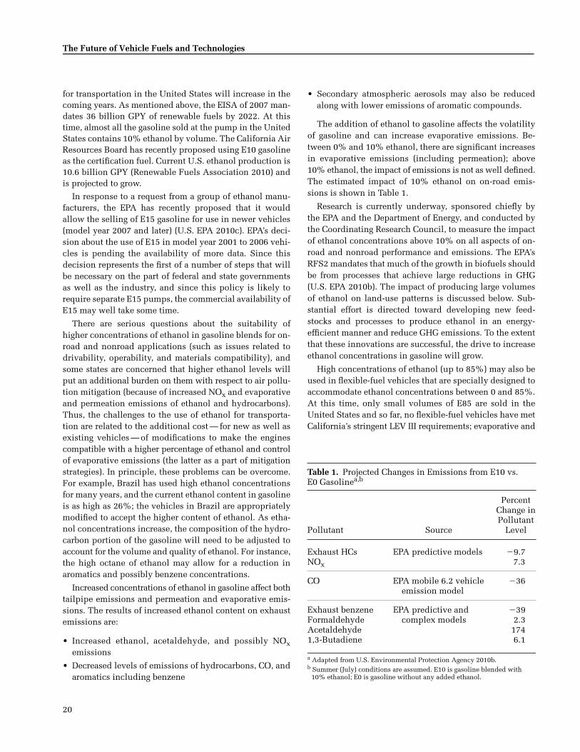
20
The Future of Vehicle Fuels and Technologies
for transportation in the United States will increase in thecoming years. As mentioned above, the EISA of 2007 man-dates 36 billion GPY of renewable fuels by 2022. At thistime, almost all the gasoline sold at the pump in the UnitedStates contains 10% ethanol by volume. The California AirResources Board has recently proposed using E10 gasolineas the certification fuel. Current U.S. ethanol production is10.6 billion GPY (Renewable Fuels Association 2010) andis projected to grow.
In response to a request from a group of ethanol manu-facturers, the EPA has recently proposed that it wouldallow the selling of E15 gasoline for use in newer vehicles(model year 2007 and later) (U.S. EPA 2010c). EPA’s deci-sion about the use of E15 in model year 2001 to 2006 vehi-cles is pending the availability of more data. Since thisdecision represents the first of a number of steps that willbe necessary on the part of federal and state governmentsas well as the industry, and since this policy is likely torequire separate E15 pumps, the commercial availability ofE15 may well take some time.
There are serious questions about the suitability ofhigher concentrations of ethanol in gasoline blends for on-road and nonroad applications (such as issues related todrivability, operability, and materials compatibility), andsome states are concerned that higher ethanol levels willput an additional burden on them with respect to air pollu-tion mitigation (because of increased NOx and evaporativeand permeation emissions of ethanol and hydrocarbons).Thus, the challenges to the use of ethanol for transporta-tion are related to the additional cost — for new as well asexisting vehicles — of modifications to make the enginescompatible with a higher percentage of ethanol and controlof evaporative emissions (the latter as a part of mitigationstrategies). In principle, these problems can be overcome.For example, Brazil has used high ethanol concentrationsfor many years, and the current ethanol content in gasolineis as high as 26%; the vehicles in Brazil are appropriatelymodified to accept the higher content of ethanol. As etha-nol concentrations increase, the composition of the hydro-carbon portion of the gasoline will need to be adjusted toaccount for the volume and quality of ethanol. For instance,the high octane of ethanol may allow for a reduction inaromatics and possibly benzene concentrations.
Increased concentrations of ethanol in gasoline affect bothtailpipe emissions and permeation and evaporative emis-sions. The results of increased ethanol content on exhaustemissions are:
• Increased ethanol, acetaldehyde, and possibly NOxemissions
• Decreased levels of emissions of hydrocarbons, CO, andaromatics including benzene
• Secondary atmospheric aerosols may also be reducedalong with lower emissions of aromatic compounds.
The addition of ethanol to gasoline affects the volatilityof gasoline and can increase evaporative emissions. Be-tween 0% and 10% ethanol, there are significant increasesin evaporative emissions (including permeation); above10% ethanol, the impact of emissions is not as well defined.The estimated impact of 10% ethanol on on-road emis-sions is shown in Table 1.
Research is currently underway, sponsored chiefly bythe EPA and the Department of Energy, and conducted bythe Coordinating Research Council, to measure the impactof ethanol concentrations above 10% on all aspects of on-road and nonroad performance and emissions. The EPA’sRFS2 mandates that much of the growth in biofuels shouldbe from processes that achieve large reductions in GHG(U.S. EPA 2010b). The impact of producing large volumesof ethanol on land-use patterns is discussed below. Sub-stantial effort is directed toward developing new feed-stocks and processes to produce ethanol in an energy-efficient manner and reduce GHG emissions. To the extentthat these innovations are successful, the drive to increaseethanol concentrations in gasoline will grow.
High concentrations of ethanol (up to 85%) may also beused in flexible-fuel vehicles that are specially designed toaccommodate ethanol concentrations between 0 and 85%.At this time, only small volumes of E85 are sold in theUnited States and so far, no flexible-fuel vehicles have metCalifornia’s stringent LEV III requirements; evaporative and
Table 1. Projected Changes in Emissions from E10 vs. E0 Gasolinea,b
Pollutant Source
Percent Change inPollutant
Level
Exhaust HCs EPA predictive models �9.7NOx 7.3
CO EPA mobile 6.2 vehicleemission model
�36
Exhaust benzene EPA predictive and complex models
�39Formaldehyde 2.3Acetaldehyde 1741,3-Butadiene 6.1
a Adapted from U.S. Environmental Protection Agency 2010b. b Summer (July) conditions are assumed. E10 is gasoline blended with
10% ethanol; E0 is gasoline without any added ethanol.

HEI Communication 16
21
permeation emissions are a major problem. If ethanol avail-ability increases and suitable materials that are compatiblewith the higher alcohol content can be used while keepingsuch vehicles affordable, the use of E85 may become morewidespread and the emissions implications of E85 may bemore important. There is a great deal of emissions certifi-cation data on E85 in flexible-fuel vehicles, but not muchresearch has been carried out to understand the relation-ships between fuel properties and in-use emissions. It islikely that E85 use will increase acetaldehyde and ethanolemissions. The optimal composition of the gasoline por-tion has also not been studied extensively. More emis-sions research in this area would be useful. Additionally,since flexible-fuel vehicles can be fueled by either regu-lar gasoline or E85, it is likely that they will run on inter-mittent blends a significant fraction of the time. Moreemission testing on intermediate blends (for instance, E40)is needed.
Other Alcohols
Research is also being conducted to develop manufac-turing processes to produce alcohols of higher molecularweight, such as tertiary-butanol and n-butanol from renew-able resources, most likely through fermentation (U.S.Department of Energy 2009). These alcohols are more com-patible with gasoline than is ethanol, and it is possible thatthey will be approved for use at higher concentrations thanethanol. Significant research must be carried out before thesealcohols are commercially viable. There are little data onemissions from these alcohols in current and future vehicles.
The use of methanol-gasoline mixtures in spark-ignitionvehicles has a number of technical challenges. Methanolhas even lower energy density than ethanol. It is not par-ticularly miscible with gasoline and is prone to phase sep-aration in the presence of small amounts of water — moreso than ethanol. The U.S. EPA has approved use of lowmethanol concentrations in gasoline (< 5%) when accom-panied by co-solvents such as tertiary-butanol. High levelsof methanol in gasoline require specially designed cars.Methanol itself is well known for its neurotoxicity, andmethanol use as a fuel can result in high emissions offormaldehyde, a toxic pollutant. Finally, methanol is usu-ally made from natural gas or, in China, from coal. If madefrom coal, the carbon footprint for methanol fuel may behigh. Increased methanol use in the United States is notlikely to happen within the outlook period, the nextdecade. China is now the world leader in methanol pro-duction and a significant amount of methanol finds its wayinto the gasoline pool. The probability of increased use ofmethanol is low in the United States, Europe, and Japan,and medium in other parts of the world such as China andIndia. It should also be noted that, in addition to its direct
use as a transportation fuel, methanol has uses in produc-ing other fuels; for example, in the production of biodieseland possibly as a source of hydrogen for fuel cells.
Natural Gas
Natural gas may be used in transportation in a numberof ways: it may be stored as compressed natural gas (CNG)or liquefied as in liquefied natural gas (LNG), and burneddirectly in spark-ignition engines. It may also be convertedto a liquid hydrocarbon fuel through chemical processingsuch as Fischer-Tropsch reactions (discussed below).With the advent of sizeable recoverable deposits of naturalgas in the United States and elsewhere, an increase in theuse of natural gas — especially for power generation — isexpected (Massachusetts Institute of Technology 2010).
CNG is a clean fuel for spark-ignition engines and itslow carbon content makes it attractive in terms of CO2emissions. It is used in many vehicles around the world,most notably in Italy and Argentina, and use is on theincrease in China. Widespread use in the United Stateswould entail a large investment in infrastructure for dis-tributing and compressing CNG. Specially modified vehi-cles would be sold with high-pressure storage cylinders.Devices that store large amounts of CNG at lower pres-sures, possibly adsorbed on a substrate, are desirable butnot currently available. Most CNG use in the U.S. transpor-tation system today is in captive fleets with central refuel-ing stations, and of these, most are composed of HDVs,such as municipal buses where the size of high-pressuretanks and the distribution issue are not serious detriments.Conversion of gasoline vehicles to CNG is possible, but isalso quite expensive in the United States.
Whereas most data on CNG use are with older technol-ogy, nonmethane hydrocarbons and CO emissions associ-ated with CNG are low. However, NOx emissions may beequal to or a little higher than a gasoline-fueled counter-part, but lower than a diesel engine; PM emissions are low.In a study with buses powered by CNG, nanoparticle emis-sions from vehicles without a DOC were reported to beabout the same as for buses equipped with a CRT; such emis-sions are suspected to arise from lubricating oil (Holmenand Ayala 2002). Formaldehyde emissions may be higherthan for gasoline and diesel engines, while other toxicemissions are generally low. Methane emissions are higherthan for gasoline- or diesel-fueled vehicles; furthering thedesign of CNG vehicles with low emissions is an area ofactive research and development.
From a GHG perspective, natural gas may also be used asa replacement for coal in generating electricity. This use ofnatural gas is a lower investment strategy than its use as anautomotive fuel, which would require large infrastructure

22
The Future of Vehicle Fuels and Technologies
capital investments. It should be noted that methane itself,the main constituent of natural gas, is a potent GHG (ap-proximately 20-fold more potent than CO2), and care mustbe taken to minimize leakage during production, distribu-tion, and use.
New supplies of natural gas in the United States arebeing obtained by shale drilling; this process requireshydraulic fracturing, or “fracking,” the rocks with waterand certain chemicals under high pressure. There are con-siderable environmental and health concerns associatedwith fracking (Kerr 2010) that are currently being investi-gated by the U.S. EPA and others.
Liquefied Petroleum Gas
Liquefied petroleum gas (LPG), which consists prima-rily of propane, is used in vehicles in plants and ware-houses. LPG is a relatively clean fuel, but is available inonly fairly small volumes; the outlook for substantiallyincreasing the supply is not optimistic.
COMPRESSION IGNITION FUELS
Petroleum Diesel
Traditional, petroleum-based diesel fuel is expected torepresent the majority of diesel fuels during the next 10 yearsand its composition will probably not change in theUnited States and Europe. In the United States, growth inthe use of diesel engines to power LDVs could have aneffect on diesel composition because refineries would bemodified to produce a higher fraction of diesel relative togasoline. The resulting changes in composition and emis-sions should be studied if this scenario is deemed likely.
Sulfur is a major source of particulate and acidic emis-sions but on-road sulfur levels in fuel sold in the UnitedStates and Europe have declined dramatically in recentyears. U.S. EPA regulations reduced sulfur in diesel fuelfrom about 2000 ppm to 500 ppm in 1995 with furtherreductions to 15 ppm in 2006; these stringent standardshave now been extended to nonroad fuel as of June 2010.In Europe, the current sulfur specification for diesel is10 ppm.* These reductions have reduced PM emissions,and enabled the introduction of catalytic aftertreatmentsystems in light- and heavy-duty diesels. However, thelack of availability of low-sulfur diesel is a major barrier tothe wide scale deployment of diesel emission controldevices in developing countries.
A great deal of research is currently devoted to the de-velopment of HCCI engines in order to improve efficiencyand reduce emissions relative to typical diesel engines. Atthis stage of development, it is not possible to define withany certainty the fuel requirements of these engines. It hasbeen suggested that the best fuel will be a minimally refinedproduct that has properties midway between gasoline anddiesel. The emissions effects associated with fuels forHCCI engines cannot be estimated at this time. It is impor-tant to follow the development of HCCI engines and makea determination if future emissions research is warranted.
Two significant sources of new diesel fuel blendstocks—or fully formulated fuels—are F-T processes (sometimesreferred to as synthetic diesel) and fatty acid esters (com-monly called biodiesel).
Fischer-Tropsch Diesel
F-T diesel is produced generally by a process consist-ing of two steps. First, a feedstock is thermally treated toproduce a synthesis gas consisting primarily of CO andhydrogen. In the second step, the synthesis gas is reactedcatalytically to produce a mixture of hydrocarbons, thecomposition of which may be adjusted by choosing re-actor design and reaction conditions. Most commercialprocesses produce either diesel fuel or lubricant basestocks. Raw F-T fuel is usually upgraded to improve qual-ity by hydrocracking and hydro-isomerization creating iso-paraffins from normal paraffins and/or removing waxymaterials to improve cold flow performance. The resultingfuel is similar to petroleum diesel in molecular weightrange (C8–C24), although the distributions may not matchexactly. The F-T diesel fuel is extremely high quality andhas low or zero aromatics and sulfur, along with a veryhigh cetane number (>70) (Alleman and McCormick 2003).F-T diesel produced from the hydroprocessing of F-T waxeshas lower energy density. It also has somewhat poorer lu-bricity than conventional diesel because lower molecularweight (C4–C12) aliphatic alcohols, which have excellentlubricity qualities, are destroyed during hydrorefining.The addition of small quantities (~200 ppm) of lubricityadditives can overcome this poor lubricity (Norton et al.1998). Catalysts and associated unit processes have beendeveloped recently that directly produce a high-qualityF-T diesel that does not require hydroprocessing andisomerization. This fuel has been shown to have betterlubricating properties than conventional diesel (Ayasse2009; Berlowitz et al. 1997; Ding et al. 2004).
F-T diesel has been shown to reduce emissions from die-sel engines significantly. In one study of a heavy-duty dieselengine, emissions relative to petroleum diesel were re-duced by 40% for PM, 20% for NOx, 41% for hydrocarbons,
* The 15-ppm sulfur limit in the United States is at the pump and includessulfur from pipeline and truck transfer. The 10-ppm sulfur limit in Europeis at the refinery gate and does not include sulfur from transfer, so the twonumbers are not directly comparable. In practice, sulfur levels in theUnited States and Europe are similar and quite low.

HEI Communication 16
23
and 30% for CO (Fanick et al. 2001). These reductions areconsistent with the properties and composition of F-T die-sel (Hochhauser 2009). In a test of a European light-dutydiesel passenger car, a 50/50 mixture of conventional andF-T diesel reduced emissions of hydrocarbons and COby about 45% and PM emissions by 22%. NOx emissionswere not affected (Schaberg et al. 2005). The benefits forreducing emissions of hydrocarbons, CO, and NOx suggesta nonlinear benefit for the mixtures. More emissions datain heavy-duty diesels with modern aftertreatment deviceswould be useful.
Various feeds may be used to produce F-T diesel—naturalgas, coal, shale, and biomass. Fuel that has properties sim-ilar to F-T diesel may also be produced by processing veg-etable oil in a refinery; the end result is commonly calledhydrogenated vegetable oil. The carbon footprint of theseprocesses and feedstocks is discussed in a later section.
A number of commercial plants to produce F-T dieselfrom natural gas and coal are in operation; others are beingstudied or planned. Natural gas produced in remote loca-tions that cannot be distributed with the existing pipelineinfrastructure may be put to other uses such as those forshipping after liquefaction or F-T conversion. LNG wouldprobably be used as a fuel to produce electricity or forhome heating in the United States. Production of F-T die-sel using biomass as a feedstock is likely to take place insmaller plants with locally grown biomass.
The most likely use of F-T diesel will be as blendstocksin standard diesel fuel. Use of F-T diesel as blendstocksallows fuel manufacturers to increase diesel productionwithout the expense of marketing a totally new fuel. Ifengine manufacturers develop new engine technology thattakes advantage of the special properties of F-T diesel,then a separate grade of fuel would have to be produced,distributed, and marketed.
The ASTM International is developing new specifica-tions (ASTM 2009) for diesel fuel derived from the low-temperature F-T process. These specifications will dealwith test methodologies and terminology for such syntheticfuels. Through this process, ASTM will address the suit-ability of these fuels as a blend component in fuels con-forming to the D975 standard, and this specification willbe used to ensure that purchasers obtain genuine syntheticdiesel fuel of high quality, which offers lower exhaust emis-sions capabilities when used in current and advanced com-pression ignition engines.
Biodiesel
Biodiesel refers to esters of fatty acids. These are usuallyfatty acid methyl esters, but may also be ethyl esters. Plantoils such as soy, palm, rapeseed (canola), and jatropha con-sist primarily of triglycerides. Biodiesel is produced from
the transesterification of these oils with alcohol, usuallymethanol. When purified, the resulting product containsoxygenated molecules that have a relatively narrow molec-ular weight distribution in the diesel fuel range. Researchis also being conducted to produce fatty acids from algaefarming. Glycerin is a significant byproduct of biodieselproduction, and research is underway to find new uses forthis product. The methanol used for transesterification isgenerally produced from natural gas or coal, and is thusnot obtained from biologic sources.
Relative to petroleum-based diesel fuel, fatty acid methylesters have a number of benefits and challenges, which aresummarized in Table 2.
The negative aspects of biodiesel performance can beovercome through blending or the use of additives or both.
While it may be used neat, biodiesel is most commonlyused as a blendstock. ASTM International has developed aspecification for pure biodiesel (2010a), and 5% (volume)biodiesel (B5) is approved for use under the diesel specifi-cation (D975). ASTM has developed a specification forhigher concentrations, B6-B20 (ASTM 2010b). Use ofbiodiesel is expected to grow in the outlook period, in partin response to the mandates contained in EISA 2007.
The emission effects of biodiesel have been studied andU.S. EPA has published a summary of emissions dataalong with a regression model (U.S. EPA 2002, 2010b). Thedata in Table 3 show that biodiesel reduces emissions ofPM, hydrocarbons, and CO and somewhat increases emis-sions of NOx. Predicted emission effects in heavy-dutydiesels are shown below for a 20% (volume) concentra-tion of biodiesel (B20) in typical diesel fuel. Other studieshave reported similar effects (Hoekman et al. 2009; Robbinset al. 2009).
Table 2. Comparison of Biodiesel with Petroleum Diesel: Properties and Performance
Advantages of Biodiesel Disadvantages of Biodiesel
Lower emissions of PM, HCs, CO, and PAHs
Near-zero sulfur content, without need for desulfurization
Lower aromatic content
Better lubricity
Higher cetane number
Lower GHG emissions
Slightly higher emissions ofNOx and possibly aldehydes
Higher viscosity
Poorer low-temperature properties
Poorer oxidative stability
Susceptible to microbial growth
(on life-cycle basis) Lower energy content
Increased engine deposits

24
The Future of Vehicle Fuels and Technologies
Because conventional diesel fuel is highly paraffinic andbiodiesel fuels contain esters, it is possible that unregulatedemissions will be affected. Based on the particular vegeta-tion source used to produce the biodiesel fuel, emissionsof formaldehyde and acetaldehyde may increase, as com-pared with a petroleum diesel (Hansen and Jensen 1997).Although quantitative information on these effects has notbeen published, one possible effect would be an increase inaldehyde emissions, because of the higher oxygen contentof the biodiesel. More research in this area will be useful.
Alcohols and Ethers
Alcohols and ethers have been proposed for use in die-sel engines, either neat or in mixtures with diesel fuel.Alcohols such as methanol and ethanol are not particu-larly miscible with diesel fuel and their use is unlikelywithin the outlook period of the next decade. Ethers suchas dimethyl ether (DME) can be good diesel fuels, but theredoes not seem to be a large incentive to introduce theminto the diesel pool. DME is also highly volatile and flam-mable; its physical properties are similar to propane. Itswidespread use in transportation would require expansionof the LPG infrastructure to transport and store it. There isinterest in DME use in Asia and some plants are being builtin China and Japan. Coal and natural gas are the primaryfeedstocks for DME production. DME can also be producedfrom the thermochemical conversion of biomass to pro-duce synthesis gas, which is then followed by the catalyticconversion of the synthesis gas to DME. Unlike any othersynthetic diesel fuel, DME virtually eliminates soot emis-sions and the need for DPFs.
SOURCE-RELATED ISSUES CONCERNING FUELS
High oil prices have driven interest in a variety of trans-portation fuel sources that are not petroleum based butbased on other sources of fossil fuels. These fuel sources in-clude tar sands, oil shale, and liquefied coal. The production
and use of these fuels could increase air and water pollu-tion and damage sensitive ecosystems, although some ofthis environmental impact could potentially be mitigatedthrough better regulation and enforcement (Bordetsky etal. 2007). As discussed in the next section, use of thesesources may also increase global GHG emissions.
Oil Sands
Currently, U.S. oil consumption is about 20 million bar-rels per day; 1.4 million barrels per day of crude oil areproduced from the oil sands in Alberta, Canada, of whichtwo-thirds is exported to the United States. According tothe Canadian Association of Petroleum Producers, oil sandsproduction is expected to grow and reach three to four timescurrent levels by 2020 (Canadian Association of PetroleumProducers 2008). Oil sands consist of a mixture: 85% sand,clay, and silt; 5% water; and 10% crude bitumen — a tarlikesubstance from which oil can be extracted. Oil sands areobtained either by strip mining or by injecting steam intothe earth to release bitumen (the in situ production pro-cess). Canada and Venezuela have the largest deposits ofoil sands in the world, and oil sands are the fastest growingsource of CO2 emissions in Canada (Grant et al. 2009).
Since the composition of crude produced from oil sandsis different than conventional crude, the composition offuel produced from oil sands may also be different. It islikely that diesel fuel produced from oil sands will containmore naphthenes than diesel produced from conventionalcrude oil; the effects on the composition of gasoline areless certain. An investigation of how fuel from oil sandsmay be different would be useful in understanding poten-tial emissions and health effects. A joint program of gov-ernment and industry in Canada compared emissions fromheavy-duty diesel engines operating on fuel derived fromoil sands and those from conventional crude (Mitchell2000). No impact of the fuel from the crude source onemissions was seen. However, the fuels were speciallyblended to have matched properties, such as aromatic con-tent. Differences in composition that might be reflected inactual blending may not be reflected in the results of theCanadian program. In addition, the tendency of these fuelsto form secondary organic aerosol is poorly understood.This area deserves more investigation.
Production of crude from oil sands generates air andwater pollution, negatively impacts the ecosystems ofboreal forests (Grant et al. 2009; Bordetsky et al. 2007), anduses large amounts of water. In addition, the holding reser-voirs for wastewater are a suspected source of contamina-tion, posing threats to humans, wildlife, and wetlands(Tenenbaum 2009). The high concentrations of pollutantssuch as naphthenic acids and heavy metals are acutelytoxic to aquatic life (Bordetsky et al. 2007).
Table 3. Changes in Emissions with the Use of B20 vs. B0 Diesela,b
Emissions Percent Change
NOx +2PM �16HCs �14CO �14
a Adapted from U.S. Environmental Protection Agency 2010b.b The table shows the impact on emissions, for all cycles, of using fuel
with 20% soybean-based biodiesel by volume (B20) compared with an average diesel fuel containing no biodiesel (B0).

HEI Communication 16
25
Oil Shale
Oil shale, a rock found in Wyoming, Utah, and Colorado,produces oil when heated to very high temperatures (pyrol-ysis). According to a RAND study, under a high-growthscenario, “an oil shale production level of 1 million barrelsper day is probably more than 20 years in the future, and3 million barrels per day is probably more than 30 yearsinto the future” (Bartis et al. 2005).
The development of commercial oil shale production isan energy-intensive process and could increase air pollu-tion (Bartis at al. 2005). Toxic elements such as arsenic andselenium could be released in the production process andmight leach into the Colorado River watershed system.Additional sources of power — using coal, natural gas, oroil shale—would likely be needed to produce oil from shaleand, depending on the fuel used for such processes, theycould generate dangerous air pollutants, including SO2,NOx, and mercury.
Coal Gasification
Conversion of coal to gasoline is also being consideredas a potential solution to supply and cost issues while alsoaddressing concerns about energy security. Although thisconversion process has been in existence for many years,first used by the Germans in World War II, current marketconditions have led to strong and renewed interest in thistechnology and there are now active plans to constructnew liquid-coal plants. According to the RAND studycited in the discussion of oil shale, coal-to-liquid produc-tion could reach as high as 3.5 million barrels per day by2030 (Bartis et al. 2005).
The effect of coal-to-liquid production on the environ-ment and on public health includes the known effectsassociated with coal extraction (including air and waterpollution), CO2 emissions, and the large amounts of waterrequired in the production process (Bordetsky et al. 2007).The effects of coal extraction and its use on the environmentand on health include landscapes destroyed by mountain-top removal and scarred by strip mining; air emissionscontaining acidic, toxic pollution from coal combustion;and water pollution caused by coal mining and combus-tion waste products (Bordetsky et al. 2007).
CROSS-CUTTING ISSUES
Climate Impact and Life-Cycle Analysis for Fuels
Alternative fuels were promoted in the 1980s as benefi-cial in terms of both air quality and energy security. As gas-oline and diesel became cleaner and emission controls ofinternal combustion engine vehicles dramatically improvedin the 1990s, the air quality benefit of alternative fuels over
gasoline and diesel gradually diminished in comparison.Since the late 1990s, alternative fuels, especially biofuels,electricity, and hydrogen gas, have been promoted for theirenergy-security benefits and GHG emission-reduction ben-efits, especially in the United States. Some fuel pathways,such as coal-to-gasoline conversion, are associated withsignificant environmental issues.
The production and use of alternative fuels in place ofpetroleum gasoline and diesel changes the amount of emis-sions during both fuel production and utilization, and mayshift emission locations upstream from vehicle tailpipes tothe fuel production and distribution stages. The changesand the shift in the location of emissions along the entirefuel cycle demand that a life-cycle analysis (LCA) of fuel–vehicle systems be conducted so that the environmentaleffects of the systems can be evaluated in a holistic andconsistent way. Since the 1990s, several comprehensiveLCA models have been developed in North America andEurope to examine the energy and emission effects of fueland vehicle systems. These models generally address emis-sions of criteria pollutants and GHGs, and the use of energyfrom different sources. One such model is the GreenhouseGases, Regulated Emissions, and Energy Use in Transpor-tation (GREET) model developed at Argonne National Lab-oratory with the support of the U.S. Department of Energy.The results of emissions models can be fed into emission-inventory models, air-quality models, and eventually health-effects models (though the LCA models themselves do notaddress health effects). Figure 1 presents sample resultsfrom the GREET model of petroleum use and GHG emis-sions from a group of fuels used in different vehicle tech-nologies (Wang and Huo 2009).
In Figure 1, the y-axis shows changes of petroleum useof different fuels relative to petroleum gasoline, represent-ing potential energy-security benefits of alternative fuels.The x-axis shows changes of CO2-equivalent emissions(including CO2, methane, and N2O) relative to petroleumgasoline. Petroleum gasoline and diesel in hybrid electricvehicle (HEV) applications realize reductions in petroleumuse because of efficiency gains of HEVs. LPG use in inter-nal combustion engines does not eliminate petroleum use,since about 40% of LPG in the United States is derivedfrom petroleum. Other nonpetroleum fuels have large petro-leum reductions. GHG emission effects vary widely amongthe alternative fuels. Dimethyl ether (DME), F-T diesel,and methanol (MeOH) from coal without CCS result indoubling of GHG emissions relative to petroleum gasoline.With CCS employed, GHG emissions associated with coal-derived fuels are equivalent to those of petroleum diesel.Fuels derived from natural gas such as CNG, DME, MeOH,and F-T diesel have small reductions or no changes in

26
The Future of Vehicle Fuels and Technologies
GHG emissions. Natural gas-based hydrogen for FCV ap-plications results in significant reductions. For EVs, GHGbenefits depend on electric generation mix. The Chinesegeneration mix with 80% of electricity from coal results insmall reductions; the U.S. mix with about 50% of electric-ity from coal results in moderate reductions; and thecleaner California mix results in large reductions. Biofuels(ethanol, biodiesel, F-T diesel, and hydrogen) in general,especially those produced from nongrain feedstocks, resultin huge GHG reductions.
Several key issues are being addressed in fuel LCA.Whereas biofuels are being promoted for GHG emissionmitigation, their effects on overall GHG emissions havebeen the subject of heated debate. In the past several years,studies were conducted to address indirect land usechanges from large scale biofuel production. Direct landuse changes are those changes that are needed for cultivat-ing feedstocks for biofuel production; indirect land usechanges refer to changes that occur somewhere beyond bio-fuel feedstock growth regions. In principle, indirect landuse changes occur because changes in global supply anddemand of food resulting from biofuel production lead tothe cultivation of new land for food production. There isincreasing acceptance of the indirect land use changesrelated to large-scale biofuel production (Searchinger et al.2009; Searchinger 2010), although debate continues on theexact magnitude of such effects and the best way to esti-mate them (Tyner et al. 2010). Thus, caution should beexercised when considering the impact of diverting a largeamount of agricultural land to crops for biofuel productionand whether, on balance, a particular biofuel is associatedwith more or fewer GHG emissions than petroleum. Inaddition, the expansion of food-crop or nonfood-crop pro-duction for future biofuel could also have a negativeimpact on water quality and could damage sensitive eco-systems (including the Gulf of Mexico through hypoxia)(Costello et al. 2009).
It should also be recognized that the U.S. crude supplyhas a large — and increasing — share of Canadian oil sandsand Venezuelan heavy, sour crude. Production of thesefuels is energy and emission intensive, as discussed else-where in this report.
Coal-based fuels such as MeOH, DME, and F-T dieselare promoted in countries such as China for benefitsrelated to energy security. China currently produces a largeamount of MeOH from coal, some of which is legally (andillegally) blended into gasoline. Liquid-fuel productionfrom coal involves coal gasification (or liquefaction) andfuels synthesis, two major processes that are capital andenergy intensive. These processes also consume a substan-tial quantity of water.
Fuel Additives
One of the greatest environmental successes of the latetwentieth century is the phaseout of lead additives in mostgasoline around the world. Lead was once widely used asan octane enhancer in gasoline because it was readilyavailable and cost-effective. Over time, lead additives wereremoved, as our understanding of the neurotoxicity oflead, especially for children, improved. Today, unleadedgasoline is used exclusively in all but about 17 countries.
The technical options available to replace lead for octaneenhancement include:
• Refinery modifications or redesign and the use of se-lected crude oils or high octane blendstocks; and
• The use of metallic octane-enhancing additives, oxygen-ates, or both, and including alcohols and ethers.
Because of the cost of refinery modifications, manyrefiners, especially those in the developing countries, haveopted for metallic additives such as methylcyclopentadi-enyl manganese tricarbonyl (MMT) and dicyclopentadienyliron (ferrocene) to replace lead. The use of metallic addi-tives is attractive because of their lower cost, ease of use,and the flexibility in octane adjustment they provide refin-ers. MMT and ferrocene do not require special handlingequipment and can be added to gasoline with existingadditive injection equipment. Use of these metallic addi-tives does not affect other gasoline properties. However,they do raise concerns regarding health effects and, insome cases, aftertreatment systems. The presence of MMTand ferrocene in gasoline leads to the formation of solid,nucleation mode particles, primarily < 10 nm diameternanoparticles (Gidney et al. 2010). These particles fall wellbelow the 23 nm cutoff of the anticipated Euro 6 particlenumber standard.
The combustion of MMT releases manganese compoundsinto the air. The inhalation of high concentrations of suchcompounds has been shown to produce symptoms that areakin to those of Parkinson’s disease. Although data on low-level exposure to such compounds — as will be generatedfrom their use as fuel additives — are sparse, there is con-cern that at low levels, health effects may take a longerperiod of time to develop, making detection and treat-ment more difficult. Because of concerns regarding theneurotoxicity of manganese compounds, the CaliforniaAir Resources Board banned the use of MMT in unleadedgasoline in 1976 (see California Air Resources Board 2005).Although the U.S. EPA has not banned the use of MMT inconventional gasoline, there is little or no use in theUnited States or most other industrialized countries. Itsuse continues in some developing nations, especially thosein Asia (including China) and Africa, which is a cause forconcern among international health experts. The literature
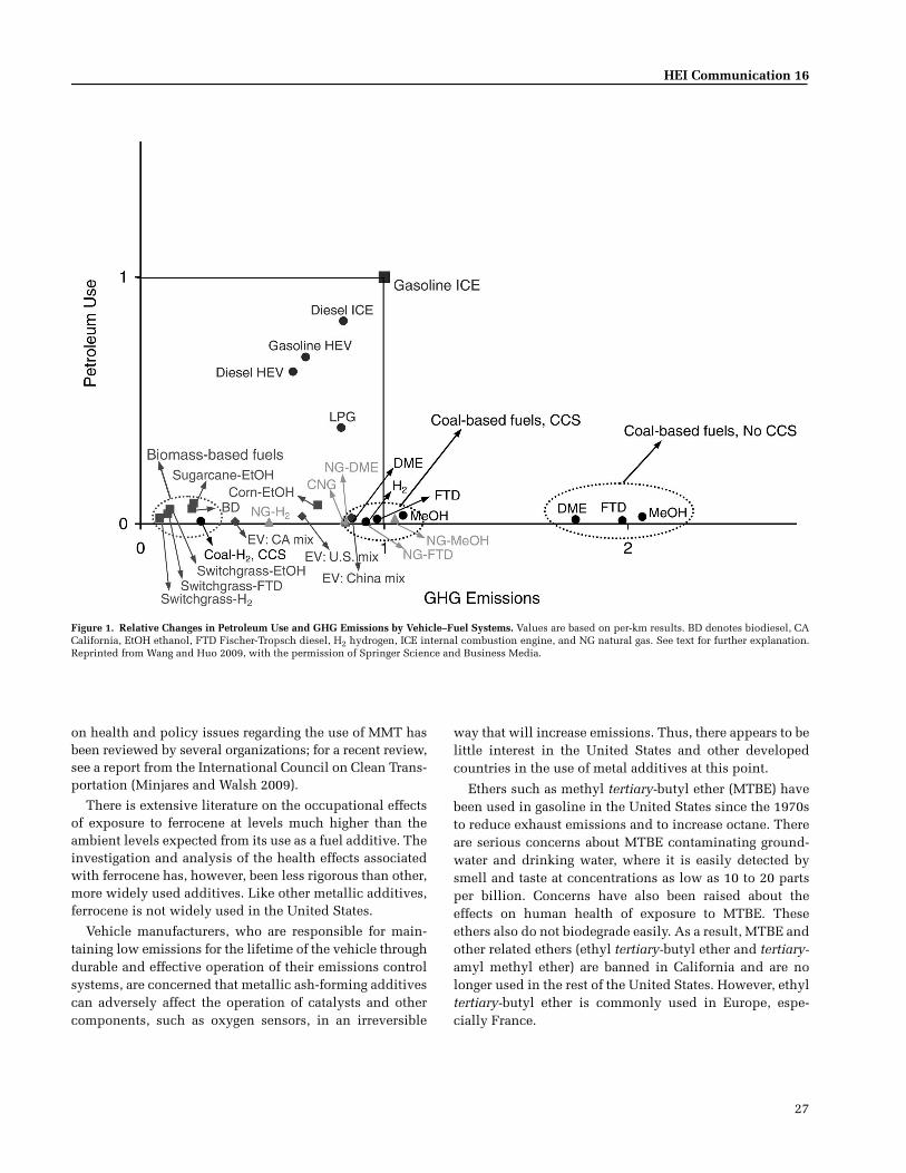
HEI Communication 16
27
on health and policy issues regarding the use of MMT hasbeen reviewed by several organizations; for a recent review,see a report from the International Council on Clean Trans-portation (Minjares and Walsh 2009).
There is extensive literature on the occupational effectsof exposure to ferrocene at levels much higher than theambient levels expected from its use as a fuel additive. Theinvestigation and analysis of the health effects associatedwith ferrocene has, however, been less rigorous than other,more widely used additives. Like other metallic additives,ferrocene is not widely used in the United States.
Vehicle manufacturers, who are responsible for main-taining low emissions for the lifetime of the vehicle throughdurable and effective operation of their emissions controlsystems, are concerned that metallic ash-forming additivescan adversely affect the operation of catalysts and othercomponents, such as oxygen sensors, in an irreversible
way that will increase emissions. Thus, there appears to belittle interest in the United States and other developedcountries in the use of metal additives at this point.
Ethers such as methyl tertiary-butyl ether (MTBE) havebeen used in gasoline in the United States since the 1970sto reduce exhaust emissions and to increase octane. Thereare serious concerns about MTBE contaminating ground-water and drinking water, where it is easily detected bysmell and taste at concentrations as low as 10 to 20 partsper billion. Concerns have also been raised about theeffects on human health of exposure to MTBE. Theseethers also do not biodegrade easily. As a result, MTBE andother related ethers (ethyl tertiary-butyl ether and tertiary-amyl methyl ether) are banned in California and are nolonger used in the rest of the United States. However, ethyltertiary-butyl ether is commonly used in Europe, espe-cially France.
Figure 1. Relative Changes in Petroleum Use and GHG Emissions by Vehicle–Fuel Systems. Values are based on per-km results. BD denotes biodiesel, CACalifornia, EtOH ethanol, FTD Fischer-Tropsch diesel, H2 hydrogen, ICE internal combustion engine, and NG natural gas. See text for further explanation.Reprinted from Wang and Huo 2009, with the permission of Springer Science and Business Media.

28
The Future of Vehicle Fuels and Technologies
CHAPTER 5. OTHER EMISSIONS ISSUES
As new technologies and fuels discussed in this paperdecrease the overall emissions of PM from the tailpipe andother sources, noncombustion emissions of PM are receivingmore attention, for example, dust from brake and tire wear,lubricating oil products and resuspended road dust (HEIPanel on the Health Effects of Traffic-Related Air Pollu-tion 2010). PM from such sources makes up an increas-ing proportion of total vehicle-related emissions and is ofparticular concern for those living in heavily populatedurban areas and close to major roads and highways. Suchemissions contain metals and organic compounds thatare of potential health concern. Although these sources ofPM are not emerging technologies in the same sense asthe others in this report, the Committee believes that theymerit attention.
Engine lubricants also affect pollutant emissions fromautomobiles. By improving engine efficiency, lubricantshelp reduce CO2 emissions and thereby GHG emissions.On the other hand, all engines consume some amount oflubricating oil, with the amount depending on factors suchas oil volatility, engine maintenance, age and design. Inaddition, some components of the oil evaporate and breakdown during use. The resulting byproducts can be directlyemitted and may also affect emission control systems. His-torically, the lubricant contribution to emissions from well-designed and maintained vehicles and engines has beenrelatively low and has been steadily decreasing. However,the advent of cleaner fuels, such as ultra-low sulfur dieselfuel, and new low emission technologies, may make thelubricant’s contribution more important on a relative basis.
BRAKE WEAR
Description of the Technology Brake lining is composedof five major components: binders; fibers; fillers; modifiers;and abrasives (Filip and Wright 1997; Filip et al. 1997;Kennedy et al. 2002). Binders are resins — typically madeof phenol formaldehyde—which act to solidify the matrix.Fibers are randomly interwoven throughout the matrixand often overlap to provide reinforcement, integrity, andstrength to the composite; examples include ceramic, min-eral, aramid, and cellulose fibers, and metal chips (e.g.,copper, steel, brass). Fillers are low-cost materials used tooccupy space, for example, barium and antimony sul-fates, kaolinite clays, magnesium and chromium oxides,powdered stone, powdered metals, and a variety of othersubstances. Modifiers are used to optimize wear character-istics, by acting as lubricants or in other ways; examples ofmodifiers include graphite and some metallic fibers. Abra-sives are used to increase friction; examples include silica,aluminum oxide, and zirconium silicate. However, brake
composition is highly variable, often proprietary, and con-stantly changing.
Likelihood of Use and Time Frame Although specific for-mulations are not standard and change frequently, thistechnology is stable and not likely to change dramatically.
Emissions of Potential Concern Dust created from brakelinings contains smaller particles than tire wear or resus-pended road dust, and comprises organic and inorganiccompounds. Examples of organic compounds present inbrake linings include the polymer aramid and phenolicspecies, although such compounds and other organic com-pounds are likely to undergo thermal decomposition ortransformation during vehicle braking. Many metals, someof which are toxic, are also present in the lining; examplesinclude chromium, nickel, copper, manganese, and anti-mony (Garg et al. 2000). Some iron may also be worn frombrake rotors of the braking system and become airborne.
The percentage of brake wear that becomes airborne ishighly variable and has been reported as anywhere be-tween 32% to 70% (Cha et al. 1983; Garg et al. 2000;Kennedy et al. 2002; Sanders et al. 2003). For the calendaryear 2009, estimated California brake-wear emissions ac-counted for 18% of the annual average statewide PM10emissions inventory and 10% of PM2.5 (California AirResources Board 2010c) (PM10 denotes PM with an aero-dynamic diameter � 10 µm, and PM2.5 PM with an aero-dynamic diameter � 2.5 µm).
There has been some concern about the use of asbestosin brake lining, especially regarding exposure of peoplewho may change brakes themselves (Occupational Safetyand Health Administration 2006; U.S. EPA 2007c). In arecent study, the California Air Resources Board sampled137 light-duty and medium-duty vehicles, ranging from1984 to 2006 model years, and found only four vehicles(i.e., 2.9%) that had asbestos (chrysotile) in their brake lin-ing; all were believed to be aftermarket products (Califor-nia Air Resources Board 2010d). Fifty-four heavy-dutyvehicles, ranging in model years 1990 to 2007, were subse-quently sampled; no asbestos-containing brake linings werefound in them.
In electric-drive vehicles, the presence of a regenerativebraking system does not impact composition of the brakelinings. Regenerative braking relies on a separate system,comprising an electric motor and motor controller. At somepoint during deceleration, the regenerative braking systemswitches over to the conventional braking system. Thus, itappears highly likely that there will be less brake wear in EVs.
Life-Cycle Issues Life-cycle issues include the exposureto toxic metals during mining and processing for the pro-duction of brake linings.
HEI Communication 16
29
Specific Regulatory Issues PM generated from brake wearis receiving attention lately because of potential health andecological effects, especially due to the presence of metalsin such PM. The state of Washington recently banned theuse of braking products that contain copper because ofconcerns about ill effects on fish. Other state-based generallaws (for example, the California Green Initiative) maymandate evaluation of some materials. Another regulatoryeffort in California is Senate Bill 346, which was signedinto law in September 2010 and sets de minimis levels(essentially a ban) of hazardous materials in brake liningssold in California. Limits are set for asbestiform fibers,chromium VI, cadmium, lead, mercury, and copper (Stateof California 2010). Based on the passage of SB 346 and theCalifornia Air Resources Board study discussed above,asbestos does not appear to be an issue in California. Themagnitude of this problem outside California is not known.However, brake lining containing asbestos is sold in devel-oping countries.
TIRE WEAR
Description of the Technology A typical tire has fivemajor components: tread; sidewall; belts; body plies; andthe bead. Tread is the portion of the tire in contact with theroad, sidewall is the side of a tire, belts are layers of steelthat run circumferentially around the tire under the tread,body plies are rubber-coated layers of textile cords that runperpendicular (radial ply) or at other angles (bias ply) tothe tread, and the bead is a high-strength steel cable coatedwith rubber that sits along the inside of the tire allowing itto stay on the wheel rim.
Tire formulations vary with desired properties such asphysical strength, wear resistance, driving type, and areproprietary (Rogge et al. 1993; Kennedy 2002; ChemRisk,Inc., and DIK Inc. 2008). In general, the major componentsof the tire are rubber (a mix of natural, polyisopropene,butadiene, and styrene-butadiene rubbers), carbon black,steel, and hydrocarbon oils and other components (Rub-ber Manufacturer’s Association 2009). The following threecomponents — rubbers, which provide structure; carbonblack, which provides reinforcement and strength; andhydrocarbon oils, which are plasticizers — each make up10% to 30% of tires. Silica is sometimes used as a partialsubstitute for carbon black, especially in low-rolling resis-tance tires, which can have up to 30% lower resistance thannormal tires. A variety of other chemicals are also added,including several metals (particularly zinc), resins, anti-degradants, cure activators and agents, accelerators, retard-ers, bonding agents, and bracing. The largest component ofthese are resins such as aromatic hydrocarbon polymersthat also serve as processing aids and can account for up to7% of tire composition.
Likelihood of Use and Time Frame Some 250 milliontires are shipped annually in the United States, with some80% used for replacement in existing vehicles. Rolling resis-tance typically consumes 4% to 7% of the total energy ex-pended by vehicles and therefore reducing rolling resistancehas been a priority for automobile and tire manufacturers(National Research Council 2006). With the exception ofthe increasing use of low-rolling resistance tires, tire tech-nology is not likely to change much in the near future.
Emissions of Potential Concern The rate of tire-tread wearis quite variable and depends on the road and driving andtire conditions. Most tire-wear particles are coarse, withless than 10% being in the fine range and a large propor-tion settle close to the road. Various studies have placedthe contribution of tire-wear particles to airborne PM at1.6% to 10% of total suspended particles in the UnitedStates (ChemRisk, Inc., and DIK Inc. 2008). In addition, theimpact of leachates of metal ions and the extraction ofwater-soluble organic compounds may be of environmen-tal concern (Weckwerth 2001).
The majority of tire-wear emissions are carbon (rangingfrom 60% to 87% of total mass), with organic carbon ac-counting for two-thirds or more of the total carbonaceousmass (Hildemann et al. 1991; Kupiainen et al. 2005; Schaueret al. 2006). Organic compounds found in tire-wear parti-cles include large amounts of n-alkanes like heptatriacon-tane, n-alkanoic acids like stearic acid, and natural resinslike dihydroabietic acid. PAHs are emitted at a lower rateof approximately 226 µg/g particle sample but remain ahealth concern. Zinc represents 1% to 2% of tire emissionsand is found in measurable amounts across tire brands andtypes (Weckwerth 2001). Smaller concentrations of othermetals such as nickel, cadmium, and copper have beenreported (Kochir 2010). It is not known how low-rollingresistance tires, which are becoming increasingly popular,affect wear emissions.
Life-Cycle Issues The major life-cycle issue is related to thedisposal of used tires. In 2007, almost 90% of the scrap tiresgenerated in the United States by weight were consumedin end-use markets, which comprise uses for tire-derivedfuel, ground rubber applications, and civil engineering(Rubber Manufacturer’s Association 2009). Open-air, un-controlled scrap-tire fires are a major concern as they emita number of organic and inorganic compounds. Scrap tiresalso serve as a breeding ground for vector-borne diseases.
Specific Regulatory Issues There are no U.S. regulationspertaining to tire materials, although in the European Union,Japan, and South Korea, regulations limit or prohibit theuse of highly aromatic extender oils to control the releaseof PAHs.

30
The Future of Vehicle Fuels and Technologies
LUBRICATING OIL
Description of the Technology Engine lubricating oil, com-posed of oil basestock and additives, has a variety of criticalfunctions in an internal combustion engine, such as reduc-ing friction and wear, removing debris and impurities, andpreventing corrosion. By reducing friction, the oils alsoimprove fuel economy and thereby reduce CO2 emissions.With newer formulations used in LDVs, there can be asmuch as 2% or more improvement in fuel economy com-pared with older technology and lubricant formulations.During use, some components of the oil inevitably breakdown, dirt and sludge build up, some lower molecularweight compounds may volatilize, and oil viscosity in-creases. Because all these factors degrade the performanceof the oil, it must be changed at regular intervals. Becauseof improvements in engine design and oil formulation,however, there is a trend toward increasing the mileageinterval between oil changes.
The oil basestock used in making lubricating oil usuallyis derived from crude oil. Synthetic base oils may be usedin higher quality lubricating oils in order to improve per-formance characteristics of the oils, such as longer drainintervals and increased wear protection. These syntheticbase oils may be made from chemical feedstocks (such aspoly alpha olefins), purified refinery streams, or the F-Tprocess (using natural gas or biomass feedstocks). Amongthe advantages of the synthetic oils is that the change intheir viscosity with temperature is low and that they areresistant to oxidative degradation.
A variety of additives is added to the base oils in manu-facturing lubricating oil, including antioxidants, detergentsand dispersants, viscosity improvers, anti-wear agents, anti-foaming agents, and dispersants (for example zinc dithio-phosphate, and compounds containing lead, copper, chro-mium, iron as well as a variety of organic and inorganiccompounds). New compounds — often proprietary — aredeveloped by various manufacturers on an ongoing basisto improve oil performance.
The American Petroleum Institute (API) categorizesbasestocks and fully formulated engine oils in variousgroups, depending on composition and performance (API2007). In Europe, categories for engine oils are defined bythe Association des Constructeurs Européens d’Automo-biles. As engine design and emission control technologieshave evolved, new lubricant testing procedures and per-formance criteria have been developed that result in morecomplex, higher quality formulations.
Likelihood of Use and Time Frame Lubricants willcontinue to be used in all combustion engines for the
foreseeable future, but the volume used annually maydecline — even as the vehicle population grows — becausemany manufacturers are adopting longer drain intervals.LDVs are moving from 3,000-mile drain intervals to asmuch as once per year or 10,000 miles; some heavy-dutymanufacturers allow up to 100,000-mile intervals whencombined with an appropriate oil analysis program.
Changes in lubricant specifications and formulationstend to occur in parallel with changes in engine technol-ogy. The aftertreatment devices used with diesel enginesare sensitive to the presence of metals and ash generatedfrom the engine and lubricants; therefore, there is muchinterest in the development of lubricant oils with lowlevels of sulfur, phosphorus, and ash precursors. Other fac-tors, however, such as new fuels and engine/vehicle tech-nologies, could affect the degree to which oil contributesto emissions.
Emissions of Potential Concern As noted, lubricants canaffect vehicle exhaust depending on factors such as engineand vehicle design, lubricant composition, engine age, driv-ing conditions, maintenance and the fuel used (Kleemanet al. 2007). Even under the best circumstances, someengine wear is to be expected from abrasion of engine parts,and the products of such wear are taken up by the oil. Var-ious constituents of the oil may also break down, volatilizeor combust, adding to engine-out emissions.
Relatively little research has been done on the impact oflubricating oil on emissions. Some base oils may containsulfur derived from their original source and which maybe emitted from the tailpipe. Ash, derived from additives(containing compounds of, for example, sulfur, phospho-rus, calcium, magnesium, zinc) or from wear of engine parts(containing iron, lead, copper, chromium) may also clogDPFs, decrease catalytic efficiency, and increase the toxic-ity of emissions. This is a particular problem for all die-sel vehicles, although it is more acute for LDVs, whichemploy smaller DPFs that are generally not serviced dur-ing the vehicle’s useful life. The challenge for both light-and heavy-duty applications is to reduce ash content with-out impairing other aspects of performance, especially nowthat extended intervals between oil changes are sought bymanufacturers and customers of both light-duty and heavy-duty vehicles. Low ash in lubricating oils is a warrantyrequirement from diesel vehicle manufacturers for post-2007 engines in the United States so that the efficiency ofaftertreatment devices is not compromised.
The impact of new fuels on oil-related exhaust has notbeen studied in much detail. Particle emissions from CNG-fueled vehicles are believed to derive from lube oil (Holmenand Ayala 2002). Other fuels, such as those containing

HEI Communication 16
31
increased ethanol and biodiesel, may interact with the oiland reduce its effectiveness. For example, certain dieselengines cannot tolerate biodiesel above 5% because the fuelgets into the oil more readily and decreases its lubricity,risking significant damage to the engine. The impact of thelubricant on evolving vehicle–fuel systems is likely tochange over the coming decade, and ongoing research sug-gests a need to evaluate lubricants more closely as an emis-sion factor.
The National Renewable Energy Laboratory is close tocompleting a detailed study on emissions related to lubri-cating oil. When published, the results of this study willprovide much needed information in this area.
Life-Cycle Issues As noted, by improving engine effi-ciency, lubricating oils decrease CO2 emissions. Other life-cycle issues are related to the source of base oil and addi-tives. The overall volume of lube oil consumption, andtherefore the volume of waste oil generated, is decreasing.Current research is focused on improving friction modifi-ers to increase fuel economy without losing oil durabilityor other performance benefits.
Specific Regulatory Issues Manufacturers comply withAPI performance specifications for manufacturing and usinglubricating oils. The EPA — during the process of vehiclecertification—ensures fairness in fuel economy testing, fac-tory fill, and other aspects of lubricant usage (U.S. EPA2010e). Used motor oil is hazardous because of its metalcontents and the presence of other compounds. Regulationsand enforcement are in place for disposing and recyclingof waste oil in the United States. Some states have showninterest in regulating aftermarket oils to help consumersavoid obsolete and poor quality oils.
CHAPTER 6. SUMMARY AND CONCLUSIONS
Since the mid 1970s, substantial progress has been madein controlling automobile emissions. With the phaseout ofleaded gasoline, deployment of the three-way catalyst,electronic ignition systems, and myriad of incrementalchanges, emissions from gasoline automobiles on the mar-ket today are a vast improvement over those of earliertimes. Whereas progress on reducing emissions from diesel-powered vehicles has until recently been at a slower pace,with the introduction of low-sulfur fuel and improved con-trol technologies, emissions from current engines are cleancompared even with 2004 engines. However, despite sig-nificant progress, many questions remain unansweredabout human exposure to air pollution and the healtheffects of such exposures.
The context in which automobiles function today hasbecome far more complex, especially in view of the mobil-ity and transportation needs of an increasing global popu-lation. Given concerns about climate change, efficiency,and energy security, there is an imperative to find newsolutions to enable mobility while overcoming problemsrelated to climate, energy security, and cost, along with airpollution. This complex situation provides the impetus forrapid development and introduction of a broad range ofnew fuels, technologies, and sources of energy to meet theneeds of the transportation sector.
The ultimate development and penetration of new fuelsand technologies will, of course, depend on a variety offactors beyond technical feasibility, including:
• Relative cost of the new feedstock or technology com-pared with the alternative
• The value of the new fuel or technology relative to theone it is replacing, including the willingness of the con-sumer to pay for a higher-cost product
• Alternative use of the proposed new materials or feed-stock (in the case of fuels)
• Taxes, incentives, and mandates
Within this larger context, HEI was founded to providetimely information and analyses on the health effects frommobile sources. To gather an authoritative outlook on theshort-term future of emerging technologies and fuels toinform HEI’s research, the HEI Board of Directors estab-lished SCET, a multidisciplinary team of engineers, fuelexperts, regulators, and other experts to help obtain a bet-ter understanding of the state of the field and explore newdevelopments that are likely to play a significant rolewithin the next 10 to 15 years. The Committee, chaired byChristine Vujovich and Alan Lloyd, with 16 other mem-bers, surveyed and evaluated new fuels and technologies,the likely time frame of their application, emissions ofpotential concern and key issues that need further atten-tion and research. The results of the Committee’s compre-hensive deliberations are presented in this report.
It is very likely that our near-term future will be a multi-fuel future. Rather than relying as extensively on oil as thesource of energy to power vehicles — most of it importedto the United States and Europe from other countries — wewill use increasing amounts of ethanol and other poten-tially renewable fuels as well as electricity. Developingfuels that are truly carbon-neutral is not yet within reach,but progress is being made. On the technology front, thereis much continued interest in further reducing traditionalemissions as well as reducing GHG emissions, improvingfuel efficiency, thereby helping reduce the carbon footprint

32
The Future of Vehicle Fuels and Technologies
from the transportation sector. Also, as we begin to reducedependence on oil as the chief energy source, the century-old domination of the conventional internal combustionengine is also expected to change substantially. Althoughthe internal combustion engine will endure through thenext 10 to 15 years, it will be supplemented, and in somecases superseded, by the electric powertrain.
Finally, in its deliberations, the Committee focusedlargely on developments and trends in the United Statesand, to a limited extent, Europe and other developed mar-kets. However, other regions of the world, especially therapidly developing countries of China and India, are in-creasingly important customers for automobiles; their mar-kets are growing faster than those of the developed coun-tries. Whereas there are expected to be some similarities inthe emergence of new fuels and technologies in the devel-oping and in the developed world, there will also be manydifferences in the nature, pace of introduction, and impactof these materials. To keep this report within bounds, weonly touched on issues that relate to developing nations,although the Committee remains interested in this impor-tant topic and may address it in future assessments.
To address the emerging fuels and technologies discussedin this report, SCET reviewed the full range of potentialchanges, focused on those that are most likely to come tomarket in the next decade, and identified those that mightpose important questions of unintended health conse-quences as they are developed and deployed. On the basisof the detailed review conducted by SCET and presentedin the previous chapters, the Committee identified the fol-lowing as key issues going forward.
INTERNAL COMBUSTION ENGINE TECHNOLOGIES
The technology chapter takes a careful look at new de-velopments in technologies for both gasoline- and diesel-powered vehicles. In the context of accelerated progress,the Committee notes several key areas that need furtherconsideration and investigation by HEI and others in thescientific community. A summary of the Committee’s eval-uation is presented in Table 4.
Gasoline Direct-Injection Technology
GDI technology is well established and expected to spreadbroadly within the gasoline engine market in the near term.Coupled with engine downsizing and turbocharging, GDIwill give a significant boost to fuel economy and the con-comitant reduction in carbon dioxide emissions. The majorconcern related to the use of GDI is higher emissions of PM,both mass and UFP emissions, although these emissions
are likely less than those from lean-burn engines. Theseemissions have not been well characterized and their poten-tial health effects are not well understood. There are alsosome indications of regulatory actions in California toreduce the mass and the number of PM from these enginesunder its LEV III standards, and actions in Europe thatcould affect the emissions of UFPs.
Selective Catalyst Reduction
SCR systems are being introduced to control the emis-sions of NOx from diesel engines. The introduction of ureaas the reducing agent gives rise to concerns regarding theformation of nitrogen-containing compounds, includingnitro-PAHs, in emissions and possibly other toxic com-pounds. Thus, even though the combination of DPF andSCR will substantially reduce criteria pollutants and un-regulated pollutants, conclusions regarding the overallrisk from air toxics are difficult to draw at this pointbecause such exhaust has not been characterized in detail.The Committee noted that the second phase of the HEIACES study will characterize exhaust from heavy-dutyengines equipped with DPF and de-NOx exhaust aftertreat-ment systems (model year 2010).
ELECTRIC DRIVE TECHNOLOGY
Engine electrification is likely to significantly expandwithin this decade, initially in the form of hybrids, withthe potential of moving to all EVs, and ultimately to FCVs.Although tailpipe emissions from such cars are reduced(as in the case of hybrids) or eliminated (in the case ofBEVs and FCVs), the Committee identified other issues thatneed attention. A potentially important issue is whetherthere are health effects associated with exposures to elec-tric and magnetic fields during operation of these vehicles.Another issue relates to the use of highly reactive metals —especially lithium — and possibly flammable electrolytesin the battery and the potential for human exposure to lith-ium during the entire life-cycle (from mining to recyclingand disposal) or in the event of automobile accidents.Finally, there is the issue of increased emissions associ-ated with electricity generation to charge EVs. In the nearterm, a large proportion of electricity in specific regions ofthe United States will continue to be produced by coal-fired power plants, potentially increasing emissions andexposure to some populations; there are also concerns aboutincreased GHG emissions from such plants. If electricity isgenerated from renewable sources, the emissions profilewill be different, and likely of less concern. There are littleor no empirical data available on these issues, and theyneed further research and investigation.

HEI Communication 16
33
Table 4. Summary of Emerging Technologies and Associated Issues
Pollutant(s) of ConcernResearchPrioritya Rationale for Priority Assigned
Engines
Gasoline direct injection–stoichiometric PM mass, UFPs H Universal use
Gasoline direct injection–lean burn PM mass, UFPs M Uncertain use
Turbocharging (gasoline) None L No issues
High-efficiency dilute gasoline engine PM mass, UFPs, HCs, aldehydesb
M Moderate use likely; little data available
Homogeneous charge compression ignition
HCs, aldehydes, CO, PMc L Use not imminent
Low temperature diesel combustion HCs, aldehydes, CO L Control of pollutants readily accomplished
Exhaust Aftertreatment
Diesel particulate filters–active and passive
NO2, UFPs, nitro-PAHs, sulfates,d metallic UFPse
L Relatively clean; generally used with selective catalytic reduction in modern engines
Retrofit diesel particulate filters NO2, UFPs, sulfates,d probable nitro-PAHs
M Same concerns as for filters used in new equipment, but much less data available
Retrofit diesel oxidization catalyst NO2, PM, sulfates,d probable nitro-PAHs
L Not widely used
Selective catalytic reduction using urea N-containing compounds, dioxinf
H Advanced Collaborative Emissions Study collecting data
NOx adsorber N2O, H2S, and other possible by-products
L Less use than selective catalytic reduction; less data; control of emissions readily accomplished
Electric Drive Technologies
Hybrid electric vehicles
Plug-in and battery electric vehicles
Fuel-cell vehicle (hydrogen)
Electromagnetic fields, lithium, and emissions from power plants
M Little data; increasing use of hybrid electric vehicles likely in near term; large-scale use of all electric vehicles possible in 10+ years
Other
Brake wear PM, metals, asbestos in some circumstances
L Regulatory efforts in place at state levels to manage composition
Tire wear PM, metals, PAHs M Emissions greater than for brake wear; has received less attention so far
Lubricating oil PM, metals M Largely unstudied area; may affect emissions directly and indirectly
a Letters denote the Committee’s conclusions on research priority levels: H denotes high, M medium, and L low.b HC and aldehyde emissions may be of concern with highly dilute stoichiometric engines.c PM emissions are an issue if stratified combustion is used.d Sulfate is produced from any sulfur in fuel or lubricating oil.e Metallic UFP emissions are a concern when metal-fuel additives are used.f Dioxin emissions may be an issue if copper is used as a catalyst in selective catalytic reduction.

34
The Future of Vehicle Fuels and Technologies
FUELS FOR INTERNAL COMBUSTION ENGINES
Consistent with other parts of this report, the fuelschapter evaluates the outlook for fuels over the next 10years. Changes in fuel composition, demand, and use pat-terns are considered for the United States, as well as forother regions of the world. While there are many commondirections, there are also areas where we expect to seenational and regional differences. As in the case of tech-nologies, the Committee emphasizes that the exact fuelmix used for transportation will depend on many otherfactors, beyond the technological possibilities. The majorthemes the Committee deemed to be significant aredescribed in the sections that follow. In addition, Table 5summarizes the outlook, or likelihood of use, for all sig-nificant fuels, some of which warrant further consider-ation and investigations by HEI and by others in thescientific community.
Use of Ethanol in Gasoline Will Increase
In response to national and regional legislative man-dates in the United States and Europe, the use of ethanol asfuel is very likely to increase substantially in the UnitedStates from 10 billion GPY in 2009 to potentially 36 billionGPY by 2022. Ethanol is widely used currently and blendedwith gasoline, typically at 10%. With specifically designedengines, nearly neat (85%) ethanol can also be used. Emis-sions from the use of fuels containing more than 10%ethanol—including the impact of blending, driving cycles,exact engine and emissions-control technology —are notwell understood. However, it is expected that the use ofethanol will lead to increased emissions of acetaldehydeand ethanol itself, and to reduced emissions of hydrocar-bons, CO and benzene. More research is needed on theemissions and operability effects of ethanol blends in on-road and nonroad applications. The outlook for other alco-hols and oxygenates is less certain at this point.
Table 5. Likelihood of New or Increased Use of Transportation Fuels in the Next Decadea
Fuel
Feedstocks
PetroleumNatural
Gas Coal
Biomass(FoodCrops)
Biomass(Cellulosicand Other)
OilSandsb
OilShalec
Gasoline Current L L — L Current M
Ethanol, in gasoline blends L L L Current L/M L L
Ether, in gasoline blends L L L Ld L L L
Diesele Current Hf L/M L L/M Current M
Biodiesel, in diesel blends — — — H L — —
Dimethyl etherg — L L — L — —
LPGh Current Current L L L L L
CNG L Current L L — L L
Methanoli L M M L L/M L L
Electricityj — H H — L/M M L
Hydrogenk L/M M L/M — L L L
a Likelihood represents the probability that the use of a fuel will grow to more than about 0.5% of total fuel supply; it is expressed as low (L), medium (M), or high (H).
b Fuel from oil sands may be associated with high GHG emissions.c Fuel from oil shale may be associated with high GHG emissions.d Significant amounts of ethyl tertiary-butyl ether are made from ethanol, especially in France.e Likelihoods shown in this row are for hydrocarbon diesels made from a variety of feedstocks.f Diesel fuel can be made from natural gas through the Fischer-Tropsch process.g Increases in the use of dimethyl ether, if any, will most likely be outside the United States.h LPG is generally separated from petroleum and natural gas. Volumes are constrained by the use of both fuels. As natural gas use increases, the availability
of LPG will likely increase as well.i Methanol use may increase in developing countries, but probably not in the United States, Europe, and Japan.j Electricity will also be produced in increasing volumes from nuclear, solar, and wind power.k Likelihoods shown in this row are for hydrogen use in fuel-cell vehicles. Hydrogen may also be produced by electrolysis of water using electricity.
Hydrogen may be used as a fuel for internal combustion engines, but this use is considered of low likelihood.

HEI Communication 16
35
Use of Fatty Acid Esters in Diesel Fuel (Biodiesel) Will Increase
There is a great deal of interest in the use of fatty acidesters in diesel fuel. Although information on emissions islimited, there is concern that the use of biodiesel will pos-sibly lead to increase in emissions of NOx and aldehydeswhile reducing emissions of hydrocarbons, CO, and PM.More research is needed on the impact of biodiesel on theemissions and operability of engines equipped with newtechnologies.
Environmental Issues Related to the Source of Fuels Will Be Important
In addition to the use of alcohols, governments and pri-vate companies have given priority to finding new sources offossil fuels. Several such sources have been identified andare being developed with increasing intensity. Introduc-tion of fuels made from nonpetroleum fossil sources—suchas coal, shale, and tar sands — may cause changes in theemissions characteristics of the fuel ultimately produced.Emissions and other effects on the environment associatedwith the production of these fuels are potentially seriousand need to be more fully understood. Some of theseimpacts are best understood through the use of LCA, sothat the effect of tailpipe emissions as well as emissions orany secondary effects from the source of power to the ulti-mate disposal of materials may be taken into account.
Use of Metallic Additives in Fuels Is a Continuing Concern
Phaseout of lead is one of the most notable developmentsof the last quarter of the twentieth century; it is expectedthat lead will be eliminated from the gasoline used in allcountries in the near term. However, the use of metal addi-tives as octane boosters or for other purposes continues tobe an area that deserves scrutiny. Although fuel suppliersin the United States do not appear to be inclined towardmetal additives, metallic fuel additives are being used inEurope and their use is being considered in some devel-oping countries. Use of manganese in gasoline and die-sel is also continuing in some developing countries. Theuse of metallic fuel additives is of concern because of theemissions—and possible health effects—of metallic nano-particles; such emissions may also adversely affect after-treatment systems.
REFERENCES
Alger T, Gingrich J, Khalek IA, Mangold B. 2010. The Roleof EGR in Emissions from Gasoline Engines. SAE Techni-cal Paper 2010-01-0353. SAE World Headquarters, Warren-dale, PA.
Alger T, Hanhe S, Roberts CE, Ryan TW. 2005. The heavyduty gasoline engine — a multi-cylinder study of a highefficiency, low emission technology. SAE Technical Paper2005-01-1135. SAE World Headquarters, Warrendale, PA.
Allansson R, Blakeman PG, Cooper BJ, Hess H, Silcock PJ,Walker AP. 2002. Optimising the Low Temperature Perfor-mance and Regeneration Efficiency of the ContinuouslyRegenerating Trap System. SAE Technical Paper 2002-01-0428. SAE World Headquarters, Warrendale, PA.
Alleman TR, McCormick RL. 2003. Fischer-Tropsch DieselFuels — Properties and Exhaust Emissions: A LiteratureReview. SAE Technical Paper 2003-01-0763. SAE WorldHeadquarters, Warrendale, PA.
American Petroleum Institute. 2007. Guidelines for Pas-senger Car Motor Oils and Diesel Engine Oils. 1509. 16thEdition (April 2007), Appendix E–API Base Oil Inter-changeability. Available from www.api.org/certifications/engineoil/pubs/index.cfm.
ASTM International. 2009. WK23320—New specificationsfor low temperature Fischer-Tropsch derived paraffinic fueloils. Initiated on 03-02-2009. Available from www.astm.org/DATABASE.CART/WORKITEMS/WK23320.htm.
ASTM International. 2010a. D6751-10 — Standard specifi-cation for biodiesel fuel blend stock (B100) for middledistillate fuels. Available from www.astm.org/Standards/D6751.htm.
ASTM International. 2010b. D7467-10 — Standard specifi-cation for diesel fuel oil, biodiesel blend (B6-B20). Avail-able from www.astm.org/Standards/D7467.htm.
Ayasse C. 2009. Low-Pressure Fischer-Tropsch Process.U.S. Patent Application Publication US 2009/0124713 A1.Available from http://ip.com/patapp/US20090124713.
Bandivadekar A, Bodek K, Cheah L, Evans C, Groode T,Heywood J, Kasseris E, Kromer M, Weiss M. 2008. On theRoad in 2035: Reducing Transportation’s Petroleum Con-sumption and GHG Emissions. Report Number LFEE 2008-05 RP. MIT Laboratory for Energy and the Environment,Cambridge, MA.
Bartis J, LaTourrette T, Dixon L, Peterson D, Cecchine G.2005. Oil Shale Development in the United States: Prospectsand Policy Issues. Prepared for the National Energy Tech-nology Laboratory of the U.S. Department of Energy. RANDCorporation, Santa Monica, CA. Available from www.rand.org/pubs/monographs/2005/RAND_MG414.pdf. Accessedon 11/04/2010.
36
The Future of Vehicle Fuels and Technologies
Berlowitz P, Cook B, Wittenbrink R. 1997. Synthetic DieselFuel and Process for Its Production, U.S. Patent 5689031.Available from www.freepatentsonline.com/5689031.html.
Biswas S, Verma V, Schauer JJ, Cassee FR, Cho AK, SioutasC. 2009. Oxidative potential of semi-volatile and non vola-tile particulate matter (PM) from heavy-duty vehicles ret-rofitted with emission control technologies. Environ SciTechnol 43:3905–3912.
Bordetsky A, Casey-Lefkowitz S, Lovaas D, Martin-Perera E,Nakagawa M, Randall B, Woynillowicz D. 2007. Driving itHome: Choosing the Right Path for Fueling North Amer-ica’s Transportation Future. Natural Resources DefenseCouncil, Western Resource Advocates, and Pembina Insti-tute. Available from www.nrdc.org/energy/drivingithome/contents.asp. Accessed on 11/04/2010.
California Air Resources Board. 2000. Diesel Risk Reduc-tion Plan Appendix IX: Diesel PM Control Technologies.CARB, Santa Monica, CA. Available from www.arb.ca.gov/diesel/documents/rrpapp.htm. Last updated 7/8/2008.
California Air Resources Board. 2005. The California Re-formulated Gasoline Regulations. CARB, Santa Monica, CA.Available from www.arb.ca.gov/fuels/gasoline/040905carfgreg.pdf.
California Air Resources Board. 2010a. Proposed Amend-ments to California’s Low-Emission Vehicle Regulations —Particulate Matter Mass, Ultrafine Solid Particle Number,and Black Carbon Emissions (preliminary discussion paper).CARB, Santa Monica, CA. Available from www.arb.ca.gov/msprog/levprog/leviii/meetings/051810/pm_disc_paper-v6.pdf. Accessed on 11/22/2010.
California Air Resources Board. 2010b. Low Carbon FuelStandard Program. CARB, Santa Monica, CA. Available fromwww.arb.ca.gov/fuels/lcfs/lcfs.htm. Last updated 10/29/2010.Accessed on 11/04/2010.
California Air Resources Board. 2010c. Statewide TotalsAverage. Annual Calendar Yr 2009. EMFAC2007 V2.3 No-vember 1, 2006. Date of Analysis 11/16/10. Data analyzedby Joe DeVita of California Air Resources Board. Availablefrom www.arb.ca.gov/msei/msei.htm.
California Air Resources Board. 2010d. Frequency of As-bestos Use in Automotive Brake Linings from On-RoadVehicles in California. Project #2R0619. Mobile Source Con-trol Division. El Monte, California. November 10, 2010.
California Code of Regulations. 2007. Chapter 14. Verifica-tion Procedure, Warranty and In-Use Compliance Require-ments for In-Use Strategies to Control Emissions fromDiesel Engines. Section 2706(b)(3), Other Requirements.
CARB, Santa Monica, CA. Available from www.arb.ca.gov/diesel/verdev/reg/revised_reg_lang_072507.pdf.
Canadian Association of Petroleum Producers. 2008. CrudeOil Forecast, Markets, and Pipeline Expansion. CAPP, Cal-gary, AB, Canada. Available from www.andrewnikiforuk.com/Dirty_Oil_PDFs/CAPP%202008%20Crude%20Oil%20Forecast,%20Markets%20&%20Pipeline%20Expansions.pdf. Posted June 2008. Accessed on 11/04/2010.
Cha S, Carter P, Bradow RL. 1983. Simulation of auto-mobile brake wear dynamics and estimation of emissions.SAE Technical Paper 831036. SAE World Headquarters,Warrendale, PA.
ChemRisk, Inc., DIK Inc. 2008. State of Knowledge Reportfor Tire Materials and Tire Wear Particles. Prepared for theWorld Business Council on Sustainable Development.ChemRisk, Inc., Pittsburg, PA and San Francisco, CA. DIK,Inc., Hannover, Germany. Available from www.wbcsd.org/web/projects/tire/SoKreportfinal.pdf. Posted 07/30/2008.Accessed on 11/08/2010.
Clayton RD, Harold MP, Balakotaiah V. 2008. NOx storageand reduction with H2 on Pt/BaO/Al2O3 monolith: Spatio-temporal resolution of product distribution. Appl Catal B84:616–630.
Coordinating Research Council. 2009a. Phase I of the Ad-vanced Collaborative Emissions Study. CRC, Alpharetta,GA. Available from www.crcao.org/reports/recentstudies2009/ACES%20Phase%201/ACES%20Phase1%20Final%20Report%2015JUN2009.pdf. Posted June 2009. Accessedon 11/3/2009.
Costello C, Griffin WM, Amy E, Landis AE, Matthews AS.2009. Impact of biofuel crop production on the formationof hypoxia in the Gulf of Mexico. Environ Sci Technol43:7985–7991.
Cumaranatunge L, Mulla SS, Yezerets A, Currier NW,Delgass WN, Ribeiro FH. 2007. Ammonia is a hydrogencarrier in the regeneration of Pt/BaO/Al2O3 NOx traps withH2. J Catal 246:29–34.
DieselNet. 2010. Emissions Standards. European Union.Car and light trucks. DieselNet. Ecopoint Inc. Availablefrom www.dieselnet.com/standards/eu/ld.php. Accessed on11/01/10.
Ding Y, Ma W, Lu Y, Lin L. 2004. Process for Direct Synthe-sis of Diesel Distillates with High Quality from SyngasThrough F-T Synthesis. U.S. Patent 6765025. Availablefrom www.freepatentsonline.com/6765025.html.
Dixon O. 2009. SCR Versus EGR: the ‘Debate’ Escalates.AutomotiveWorld.com. Available from www.automotive

HEI Communication 16
37
world.com/news/commercial-vehicles/76975-scr-versus-egr-the-debate-escalates. Accessed on 11/03/2010.
Epling WS, Campbell LE, Yezerets A, Currier NW, Parks JE.2004. Overview of the fundamental reactions and degrada-tion mechanisms of NOx storage/reduction catalysts. CatalRev 46:163–245.
Fanick ER, Schubert PF, Russell BJ, Tomlinson HL, FreerksRL. 2001. The Comparison of Emissions Characteristics ofConventional, Hydrotreated, and Fischer-Tropsch DieselFuels in a Heavy Duty Diesel Engine. SAE Technical Paper2001-01-3519. SAE World Headquarters, Warrendale, PA.
Farber M, Harris S. 1984. Kinetics of NH3-NO reactions onvanadium oxide catalysts. J Phys Chem 88:680–682.
Filip P, Wright MA. 1997. Automotive brake lining charac-terization. SAE Technical Paper 973024. SAE World Head-quarters, Warrendale, PA.
Filip P, Wright MA, Marx DT. 1997. On-highway brakecharacterization and performance evaluation. MateriallySpeaking 11:2–7.
Fino D. 2007. Diesel emission control: Catalytic filters forparticulate removal. Sci Technol Adv Mater 8:93–100.
Fulks G, Fisher GB, Rahmoeller K, Wu MC, D’Herde E,Tan J. 2009. A Review of Solid Materials as AlternativeAmmonia. Sources for Lean NOx Reduction with SCR.SAE Technical Paper 2009-01-0907. SAE World Headquar-ters, Warrendale, PA.
Garg BD, Cadle SH, Mulawa PA, Groblicki PJ, Laroo C, ParrGA. 2000. Brake wear particulate matter emissions. EnvironSci Technol 34:4463–4469.
Gense R, Weilenmann M, McCrae I. 2006. Latest Insightsinto Direct NO2 Emissions from Road Transport, the CurrentState of Knowledge. Presented at 2nd Conference Environ-ment & Transport, Reims, France. TNO, The Netherlands,EMPA, Switzerland, and TRL, UK.
Gidney JT, Twigg MV, Kittelson DB. 2010. Effect of organo-metallic fuel additives on nanoparticle emissions from agasoline passenger car. Environ Sci Technol 44:2562–2569.
Grant J, Dyer S, Woynillowicz D. 2009. Clearing the Air onOil Sands Myths. The Pembina Institute, Drayton Valley,AB, Canada. Available from http://pubs.pembina.org/reports/clearing-the-air-report.pdf. Accessed on 11/04/2010.
Green Car Congress. 2008. A New Food/Fuel Issue: Ureafor SCR Emissions Treatment? Available from www.greencarcongress.com/2008/11/a-new-foodfuel.html. Accessedon 11/03/2010.
Green Car Congress. 2009. Tenneco and GE Transportationto Develop Hydrocarbon-SCR Technology for Diesel Emis-sion Aftertreatment. Available from www.greencarcongress.com/2009/02/tenneco-and-ge.html. Accessed on 11/03/2010.
Grose M, Sakurai H, Savstrom J, Stolzenburg MR, Watts Jr.WF, Morgan CG, Murray IP, Twigg MV, Kittelson DB,McMurry PH. 2006. Chemical and physical properties ofultrafine diesel exhaust particles sampled downstream ofa catalytic trap. Environ Sci Technol 40:5502–5507.
Hansen, KF, Jensen MG. 1997. Chemical and BiologicalCharacteristics of Exhaust Emissions from a DI DieselEngine Fuelled With Rapeseed Oil Methyl Ester (RME).SAE Technical Paper 971689. SAE World Headquarters,Warrendale, PA.
Havenith C, Verbeek RP. 1997. Transient performance ofurea deNOx catalyst for low emissions heavy-duty dieselengines. SAE Technical Paper 970185. SAE World Head-quarters, Warrendale, PA.
HEI Panel on the Health Effects of Traffic-Related AirPollution. 2010. Traffic Related Air Pollution: A CriticalReview of the Literature on Emissions, Exposure, andHealth Effects. HEI Special Report 17. Health Effects Insti-tute, Boston, MA.
Heeb NV, Zenneg M, Gujer E, Honegger P, Zeyer K, GfellerU, Wichser A, Kohler M, Schmid P, Emmenegger L, UlrichA, Wenger D, Peterman JL, Czerwinski J, Mosimann T,Kasper M, Mayer A. 2007. Secondary effects of catalyticdiesel particulate filters: Copper-induced formation ofPCDD/Fs. Environ Sci Technol 41:5789–5794.
Heikkilä J, Rönkkö T, Lähde T, Lemmetty M, Arffman A,Virtanen A, Keskinen J, Pirjola L, Rothe D. 2009. Effect ofopen channel filter on particle emissions of modern dieselengine. J Air Waste Manag Assoc 59:1148–1154.
Heywood JB, Welling OZ. 2009. Trends in PerformanceCharacteristics of Modern Automobile SI and Diesel Engines.SAE Technical Paper 2009-01-1892. SAE, Warrendale, PA.
Hildemann LM, Markowski GR, Cass GR. 1991. Chemicalcomposition of emissions from urban sources of fineorganic aerosol. Environ Sci Technol 25:744–759.
Hochhauser AM. 2009. Review of Prior Studies of FuelEffects on Vehicle Emissions. SAE Paper 2009-01-1181.SAE World Headquarters, Warrendale, PA.
Hoekman SK, Gertler A, Broch A, Robbins C. 2009. Inves-tigation of biodistillates as potential blenders for transpor-tation fuels. Final Report, CRC Project number AVFL-17.Coordinating Research Council, Alpharetta, GA. Available

38
The Future of Vehicle Fuels and Technologies
from www.crcao.com/reports/recentstudies2009/AVFL-17/CRC%20Report%20No%20AVFL-17%20June%202009_f.pdf. Posted June 2009. Accessed 12/07/2010.
Holmen BA, Ayala, A. Ultrafine PM emissions from naturalgas, oxidation-catalyst diesel, and particle-trap diesel heavy-duty transit buses. Environ Sci Technol 36:5041–5050.
Hori Ma, Oguchi M. 2004. Feasibility study of urea SCRsystems on heavy-duty commercial vehicles. SAE Paper2004-01-1944. SAE World Headquarters, Warrendale, PA.
Jacoby M, J Jiang. 2010. Securing the Supply of Rare Earths.Chem Eng News 88:9–12.
J.D. Power and Associates. 2010. Drive Green 2020: MoreHope than Reality? A Special Report. Available from http://businesscenter.jdpower.com/JDPAContent/CorpComm/pdfs/DriveGreen2020_102610.pdf. Accessed on 11/04/2010.
Johnson Matthey Emission Control Technologies. 2009.Johnson Matthey’s Latest Generation CRT(R) ParticulateFilter Achieves EPA and CARB Verification while MeetingNO(2) Slip Requirements for On-Road Vehicle PM, HC andCO Reduction. Available from http://ect.jmcatalysts.com/news2.asp?id=59. Accessed on 11/22/2010.
Johnson T. 2008. Diesel engine emissions and their con-trol: An overview. Platinum Metals Rev 52:23–37.
Johnson TV. 2010. Review of diesel emissions and con-trol. SAE Paper 2010-01-0301. SAE World Headquarters,Warrendale, PA. Available from http://papers.sae.org/2010-01-0301.
Kennedy P, Gadd J, Moncrieff I. 2002. Emission Factors forContaminants Released by Motor Vehicles in New Zealand.Prepared for Ministry of Transport and Infrastructure forthe Public Good. Auckland, New Zealand. Available fromwww.transport.govt.nz/research/Documents/stormwater_emission_factors.pdf. Accessed on 11/08/2010.
Kerr RA. 2010. Energy. Natural gas from shale bursts ontothe scene. Science 328:1624–1626.
Kleeman MJ, Robert MA, Riddle SG, Jakober CA. 2007.Characterization of Ultrafine and Fine Particulate MatterEmissions from Heavy-Duty Diesel Vehicles. CRC ReportNo. E-55-59 1.5a. Coordinating Research Council, Al-pharetta, GA. Available from www.crcao.com/reports/recentstudies2007/E-55-59/E-55-59%201.5a%20HDDV_Final_Report_080907.pdf. Published May 2007. Accessed on12/02/2010.
Kochir B. 2010. Input of Tyre Abrasion Particles into Road-side Soils. The Federal Highway Research Institute (BASt),Germany: Report 188.
Kromer MA, Heywood JB. 2007. Electric Powertrains: Op-portunities and Challenges in the U.S. Light-Duty VehicleFleet. Publication Number LFEE 2007-03 RP. Massachu-setts Institute of Technology, Sloan Automotive Laboratory,Laboratory for Energy and the Environment, Cambridge,MA. Available from http://web.mit.edu/mitei/lfee/programs/archive/publications/2007-03-rp.pdf.
Kupiainen KJ, Tervahattu H, Raisanen M, Makela T, AurelaM, Hillamo R. 2005. Size and composition of airborne par-ticles from pavement wear, tires, and traction sanding.Environ Sci Technol 39:699–706.
Laroo C. 2010. EPA SCR Unregulated Emissions Test Pro-gram: Dioxin, furan, PCB, and PAH emissions from a com-pression ignition engine utilizing CuZ SCR. Presented atthe SAE 2010 World Congress, Detroit, MI, on April 13,2010. Available from the author at U.S. EnvironmentalProtection Agency, Office of Transportation and Air Qual-ity, Assessment and Standards Division, Washington, D.C.
Lietti L, Nova I, Forzatti P. 2008. Role of ammonia in thereduction by hydrogen of NOx stored over Pt–Ba/Al2O3lean NOx trap catalysts. J Catal 257:270–282.
Ligternik, N, de Lange R, Vermeulen R, Dekker H. 2009.On-road NOx emissions of Euro-V Trucks. MON-RPT-033-DTS-2009-03840. TNO Science and Industry, Delft, the Neth-erlands. Available from www.airclim.org/news/documents/TNO_Report.pdf. Accessed on 11/03/2010.
Lindholm A, Currier NW, Li J, Yezerets A, Olsson L. 2008.Detailed kinetic modeling of NOx storage and reductionwith hydrogen as the reducing agent and in the presence ofCO2 and H2O over a Pt/Ba/Al catalyst. J Catal 258:273–288.
Liu Z, Woo SI. 2006. Recent advances in catalytic deNOxscience and technology. Catal Rev 48:43–89.
Majewski WA. 2005a. Selective Catalytic Reduction. Die-sel Net. Ecopoint Inc. Available from www.dieselnet.com/tech/cat_scr.html. Accessed on 11/22/2010.
Majewski WA. 2005b. SCR systems for mobile engines.Diesel Net. Ecopoint Inc. Available from www.dieselnet.com/tech/cat_scr_mobile.html. Accessed on 11/22/2010.
Majewski WA. 2007. NOx Adsorbers. Diesel Net. EcopointInc. Available from www.dieselnet.com/tech/cat_nox-trap.html. Accessed on 11/22/2010.
Majewski WA. 2009. Diesel Oxidation Catalyst. Diesel Net.Ecopoint Inc. Available from www.dieselnet.com. Accessedon 11/22/2010.
Maricq MM, Chase RE, Xu N, Laing PM. 2002. The effectsof the catalytic converter and fuel sulfur level on motor

HEI Communication 16
39
vehicle particulate matter emissions: Light duty dieselvehicles. Environ Sci Technol 36:283–289.
Massachusetts Institute of Technology. 2010. The Future ofNatural Gas: An Interdisciplinary MIT Study. Interim report.MIT Energy Initiative, Cambridge, MA. Available from http://web.mit.edu/mitei/research/studies/report-natural-gas.pdf.Accessed on 11/22/2010.
Mayer A, Czerwinski J, Compte P, Jaussi F. 2009. Proper-ties of Partial Flow and Coarse Pore Deep Bed Filters Pro-posed to Particle Emissions of Vehicle Engines. SAETechnical Paper 2009-01-1087. SAE World Headquarters,Warrendale, PA.
Minjares R, Walsh M. 2009. Methylcyclopentadienyl Man-ganese Tricarbonyl (MMT): A Science and Policy Review.International Council on Clean Transportation. San Fran-cisco, CA.
Mitchell K. 2000. Effects of Fuel Properties and Source onEmissions from Five Different Heavy Duty Diesel Engines.SAE Technical Paper 2000-01-2890. SAE World Headquar-ters, Warrendale, PA.
Mohr M, Lehmann U, Margaria G. 2003. Acea Programmeon the Emissions of Fine Particulates from Passenger Cars(2)-Part 1: Particle Characterisation of a Wide Range ofEngine Technologies. SAE Technical Paper 2003-01-1889.SAE World Headquarters, Warrendale, PA.
National Research Council. 2006. Tires and Passenger Ve-hicle Fuel Economy: Informing Consumers, Improving Per-formance. Transportation Research Board Special Report286. Transportation Research Board. National AcademyPress, Washington DC.
National Research Council. 2008. Transitions to Alterna-tive Technologies — A Focus on Hydrogen. Committee onAssessment of Resource Needs for Fuel Cell and HydrogenTechnologies. National Academy Press, Washington, DC.
National Research Council. 2010. Assessment of fuel econ-omy technologies for light duty vehicles (Prepublicationcopy). Committee on the Assessment of Technologies forImproving Light-Duty Vehicle Fuel Economy. NationalAcademy Press, Washington, DC.
Norton P, Vertin K, Bailey B, Clark NN, Lyons DW, GoguenS, Eberhardt J. 1998. Emissions from Trucks using Fischer-Tropsch Diesel Fuel. Society for Automotive Engineer-ing, SAE Paper 982526. SAE World Headquarters, Warren-dale, PA.
Occupational Safety and Health Administration. 2006.Asbestos-Automotive Brake and Clutch Repair Work. Safety
and Health Information Bulletin. U.S. Department of Labor.Available from www.osha.gov/dts/shib/shib072606.html.Posted on 07/26/2006. Accessed on 12/07/2010.
Parks JE, West B, Huff S. 2008. Characterization of LeanNOx Trap Catalysts with In-Cylinder Regeneration Strate-gies. SAE Technical Paper 2008-01-0448. SAE World Head-quarters, Warrendale, PA.
Parvulescu VI, Grange P, Delmon B. 1998. Catalytic removalof NO. Catalysis Today 46:233–316.
Pihl J, Parks J, Daw C. 2006. Product Selectivity DuringRegeneration of Lean NOx Trap Catalysts. SAE TechnicalPaper 2006-01-3441. SAE World Headquarters, Warren-dale, PA.
Ravishankara AR, Daniel JS, Portmann RW. 2009. Nitrousoxide (N2O): The dominant ozone-depleting substance emit-ted in the 21st century. Science 329:123–125.
Renewable Fuels Association. 2010. Ethanol Facts. Avail-able from www.ethanolrfa.org/pages/statistics/#A. Accessedon 11/03/2010.
Richards P, Vincent MW, Johansen K, Mogensen G. 2006.Metal Emissions, NO2 and HC Reduction from a Base MetalCatalysed DPF/FBC System. SAE Technical Paper 2006-01-0420. SAE World Headquarters, Warrendale, PA.
Robbins C, Hoekman SK, Gertler A, Broch A, NatarajanM. 2009. Biodistillate Transportation Fuels 2. — EmissionsImpacts. SAE Technical Paper 2009-01-2724. SAE WorldHeadquarters, Warrendale, PA.
Rogge WF, Hildemann LM, Mazurek MA, Cass GR,Simoneit BRT. 1993. Sources of fine organic aerosol 3.Road dust, tire debris, and organometallic brake liningdust — roads as sources and sinks. Environ Sci Technol27:1892–1904.
Rohart E. 2008. Acidic Zirconia Materials for Durable NH3-SCR deNOx catalysts. SAE Technical Paper 2008-01-1022.SAE World Headquarters, Warrendale, PA.
Rubber Manufacturers Association. 2009. Scrap Tire Mar-kets in the United States: 9th Biennial Report. RMA, Wash-ington, DC. Available from www.rma.org/getfile.cfm?ID=985&type=publication. Accessed on 11/08/2010.
Salvat O, Marez P, Belot G. 2000. Passenger Car SerialApplication of a Particulate Filter System on a Common-Rail, Direct-Injection Diesel Engine. SAE Technical Paper2000-01-0473. SAE World Headquarters, Warrendale, PA.
Sanders PG, Xu N, Dalka TM, Maricq M. 2003. Airbornebrake wear debris: Size distributions, composition, and a

40
The Future of Vehicle Fuels and Technologies
comparison of dynamometer and vehicle tests. Environ SciTechnol 37:4060–4069.
Schaberg P, Botha J, Schnell M, Hermann H-O, Pelz N,Maly R. 2005. Emissions Performance of GTL Diesel Fueland Blends with Optimized Engine Calibrations. SAETechnical Paper 2005-01-2187. SAE World Headquarters,Warrendale, PA.
Schauer JJ, Lough GC, Shafer MM, Christensen WF, ArndtMF, DeMinter JT, Park JS. 2006. Characterization of MetalsEmitted from Motor Vehicles. Research Report 133. HealthEffects Institute, Boston MA.
Searchinger TD. 2010. Biofuels and the need for additionalcarbon. Environ Res Lett 5:024007.
Searchinger TD, Hamburg SP, Melilo J, Chameides W, HavlikP, Kammen DM, Likens GE, Lubowski RN, Obersteiner M,Oppenheimer M, Robertson GP, Schlesinger WH, TilmanGD. 2009. Climate change. Fixing a critical climate account-ing error. Science 326:527–528.
Service RF. 2010. Rare earth elements. Chinese policiescould pinch U.S. efforts to make electric vehicles. Science329:377.
Sluder CS, Storey JME, Lewis SA, Lewis LA. 2005. LowTemperature Urea Decomposition and SCR Performance.SAE Technical Paper 2005-01-1858. SAE World Head-quarters, Warrendale, PA.
State of California. 2010. Hazardous materials: motor vehi-cle brake friction materials. Senate Bill No. SB 346. Availablefrom http://info.sen.ca.gov/pub/09-10/bill/sen/sb_0301-0350/sb_346_bill_20100927_chaptered.pdf. Accessed on12/02/2010.
Swanson JJ, Kittelson DB, Watts WF, Gladis DD, Twigg MV.2009. Influence of storage and release on particle emissionsfrom new and used CRTs. Atmos Environ 43:3998–4004.
Tashiro K, Koga K, Iwachido K, Tamura Y, Nakajima H. 2001.Development of new technologies for exhaust-emissioncontrol catalysts and advanced catalytic-reaction controlsfor gasoline direct-injection engines. Mitsubishi MotorsTechnical Review 16–24.
Tenenbaum DJ. 2009. Oil Sands Development: A Health RiskWorth Taking? Environ Health Perspect 117:A150–A156.
Toussimis G, Lois E, Luders H. 2000. Influence of exhaustaftertreatment devices on heavy-duty diesel engine’s par-ticulate emissions. J Propul Power 16:636–640.
Twigg MV. 2007. Progress and future challenges in con-trolling automotive exhaust gas emissions. Appl Catal B:Environ 70:2–15.
Twigg MV. 2009. Compact diesel filters. Ingenia 38:34–39.
Twigg MV, Phillips PR. 2009. Cleaning the Air We Breathe— Controlling Diesel Particulate Emissions from PassengerCars Emission Control. Platinum Metals Rev 53:27–34.
Tyner WE, Taheripour F, Zhuang Q, Birur D, Baldos U.2010. Land Use Changes and Consequent CO2 Emissionsdue to US Corn Ethanol Production: A ComprehensiveAnalysis, Final Report (Revised). Department of Agricul-tural Economics, Purdue University. Available from www.transportation.anl.gov/pdfs/MC/625.PDF.
U.S. Department of Energy. 2009. Alternative & AdvancedFuels. Available from www.afdc.energy.gov/afdc/fuels. Lastupdated 10/25/2010. Accessed on 11/03/2010.
U.S. Department of Energy. 2010. Oil and crude petroleumproducts explained; data and statistics. Energy Informa-tion Administration. Available from www.eia.gov/energyexplained/index.cfm?page=oil_home#tab2. Updated 09/28/2010. Accessed on 11/03/2010.
U.S. Environmental Protection Agency. 1999. Heavy-Duty Diesel Emission Reduction Project Retrofit/RebuildComponent. EPA 420-R-99-014. Office of Mobile Sources,Washington, D.C. Available from www.epa.gov/cleandiesel/documents/420r99014.pdf.
U.S. Environmental Protection Agency. 2002. A Comprehen-sive Analysis of Biodiesel Impacts on Exhaust Emissions,draft report. EPA 420-P-02-001. Office of Transportationand Air Quality. Available from www.epa.gov/oms/models/analysis/biodsl/p02001.pdf.
U.S. Environmental Protection Agency. 2007a. Control ofHazardous Air Pollutants From Mobile Sources. Final Rule.40 CFR Parts 59, 80, 85, and 86. Fed Regist 72:8428–8570.
U.S. Environmental Protection Agency. 2007b. Energy Inde-pendence and Security Act. Available from www.epa.gov/regulations/laws/eisa.html. Last updated 8/18/2010.
U.S. Environmental Protection Agency. 2007c. CurrentBest Practices for Preventing Asbestos Exposure AmongBrake and Clutch Repair Workers—April 2007. Office ofPollution Prevention and Toxics. www.epa.gov/asbestos/pubs/brakesbrochure.html. Last Updated 04/22/2010. Ac-cessed on 12/7/2010.
U.S. Environmental Protection Agency. 2008. Staff Techni-cal Report: Cost and Effectiveness Estimates of Technolo-gies Used to Reduce Light-duty Vehicle Carbon DioxideEmissions. EPA/420/R/08/008. Available from www.epa.gov/oms/climate/420r08008.pdf.

HEI Communication 16
41
U.S. Environmental Protection Agency. 2009. IRIS Toxico-logical Review of Cerium Oxide and Cerium Compounds(Interagency Science Discussion Draft). EPA/635/R-08/002.Available from http://cfpub.epa.gov/ncea/cfm/recordisplay.cfm?deid=214572.
U.S Environmental Protection Agency. 2010a. Our Nation’sAir: Status and Trends through 2008. Office of Air QualityPlanning and Standards. EPA-454/R-09-002. Washington, DC.
U.S. Environmental Protection Agency. 2010b. RenewableFuel Standard Program (RFS2) Regulatory Impact Analysis;Chapter 3. EPA-420-R-10-006. Office of Transportation andAir Quality, Washington, D.C. Available from www.epa.gov/otaq/fuels/renewablefuels/regulations.htm.
U.S. Environmental Protection Agency. 2010c. ProposedRule: Regulation to Mitigate the Misfueling of Vehicles andEngines with Gasoline Containing Greater than Ten VolumePercent Ethanol and Modifications to the Reformulated andConventional Gasoline Programs. Federal Register (pend-ing). Available from www.epa.gov/otaq/regs/fuels/additive/e15/e15-labeling-nprm.pdf. Accessed on 11/03/2010.
U.S. Environmental Protection Agency. 2010d. Regulation ofFuels and Fuel Additives: 2011 Renewable Fuel Standards.Proposed Rule. 40 CFR Part 80. Fed Reg 75:42238–42268.
U.S. Environmental Protection Agency, 2010e. Use of GF-5Engine Oil in Gasoline Fueled EPA Test Vehicles. Letter to“Dear Manufacturer.” CISD-10-11 (LDV/LDT/MDPV/HDV).Dated July 1, 2010. Available from http://iaspub.epa.gov/otaqpub/display_file.jsp?docid=22579&flag=1.
U.S. Environmental Protection Agency and National High-way Traffic Safety Administration. 2010. Draft Joint Techni-cal Support Document, Proposed Rulemaking to EstablishLight-Duty Vehicle Greenhouse Gas Emission Standardsand Corporate Average Fuel Economy Standards. FinalRule. Fed Reg 75:25324–25728.
Vaaraslahti K, Virtanen A, Ristimaki J, Keskinen J. 2004.Nucleation mode formation in heavy-duty diesel exhaustwith and without a particulate filter. Environ Sci Technol38:4884–4890.
Vincent MW, Richards PJ, Dementhon JB, Martin B. 1999.Improved Diesel Particulate Filter Regeneration Perfor-mance Using Fuel Soluble Additives. SAE Technical Paper1999-01-3562. SAE, Warrendale, PA. Available from http://papers.sae.org/1999-01-3562/.
Vincent MW, Richards PJ. 2000. The Long Distance RoadTrial of a Combined Diesel Particulate Filter and FuelAdditive. SAE Technical Paper 2000-01-2849. SAE World
Headquarters, Warrendale, PA. Available from http://papers.sae.org/2000-01-2849/.
Wang MQ, Huo. 2009. Transportation: Meeting the dualchallenges of achieving energy security and reducing green-house gas emissions. Front. Energy Power Eng. China 3:212–225.
Weckwerth G. 2001. Verification of traffic emitted aerosolcomponents in the ambient air of Cologne (Germany). AtmosEnviron 35:5525–5536.
Wuebbles DJ. 2009. Nitrous oxide: No laughing matter.Science 326:56–57.
Xu L, Watkins W, Snow R, Graham G, McCane R, LambertC, Carter RO. 2007. Laboratory and engine study of urea-related deposits in diesel urea-SCR after-treatment sys-tems. SAE Technical Paper 2007-01-1582. SAE WorldHeadquarters, Warrendale, PA. Available from http://papers.sae.org/2007-01-1582/.
Yezerets A, Currier NW, Stroia BJ, Li J, Hess H, Chen H,Walker A. 2007. Development of a NOx Adsorber Systemfor Dodge Ram 2007 Heavy Duty Pickup Truck. Presented atthe 2007 Diesel Engine-Efficiency and Emissions Research(DEER) Conference, Detroit, MI. Available from www1.eere.energy.gov/vehiclesandfuels/pdfs/deer_2007/session3/deer07_yezerets.pdf. Accessed on 11/03/2010.
Zhan R, W Li, ST Eakle, P Weber. 2010. Development of aNovel Device to Improve Urea Evaporation, Mixing andDistribution to Enhance SCR Performance. SAE TechnicalPaper 2010-01-1185. SAE World Headquarters, Warrendale,PA. Available from http://papers.sae.org/2010-01-1185/.
ABBREVIATIONS AND OTHER TERMS
ACES Advanced Collaborative Emissions Study
API American Petroleum Institute
BEV battery-powered electric vehicle
CCRT catalytic continuously regenerating technology
CCS carbon capture and storage
CNG compressed natural gas
CO carbon monoxide
CO2 carbon dioxide
CRT continuously regenerating trap
DME dimethyl ether
DOC diesel oxidation catalyst
DPF diesel-exhaust particle filter

42
The Future of Vehicle Fuels and Technologies
EGR exhaust gas recirculation
EISA Energy Independence and Security Act
EU European Union
EVs electric vehicles
FCVs fuel-cell vehicles
F-T Fischer-Tropsch
g/bhp-hr grams per brake horsepower-hour
GDI gasoline direct-injection
GHG greenhouse gas
GREET Greenhouse Gases, Regulated Emissions, and Energy Use in Transportation
GPY gallons per year
H2 hydrogen
H2S hydrogen sulfide
HC hydrocarbon
HCCI homogeneous charge compression ignition
HDD heavy-duty diesel
HCN hydrogen cyanide
HEDGE high-efficiency dilute gasoline engine
HEVs hybrid electric vehicles
LCA life-cycle analysis
LDVs light duty vehicles
LEV III Low-Emission Vehicle III standards
LNG liquefied natural gas
LPG liquefied petroleum gas
MeOH methanol
MMT methylcyclopentadienyl manganese tricarbonyl
MTBE methyl tertiary-butyl ether
N2O nitrous oxide
NAC NOx adsorber catalyst
NH3 ammonia
NRC National Research Council
NO nitric oxide
NO2 nitrogen dioxide
NOx oxides of nitrogen
PAHs polycyclic aromatic hydrocarbons
PHEVs plug-in hybrid electric vehicles
PM particulate matter
PMP Europe’s Particulate Measurement Programme
ppm parts per million
RFS Renewable Fuels Standard
SAE Society of Automotive Engineers
SCET Special Committee on Emerging Technologies
SCR selective catalytic reduction
SO2 sulfur dioxide
SOx sulfur oxides
U.S. DOE U.S. Department of Energy
U.S. EPA U.S. Environmental Protection Agency
UFPs ultrafine particles

A C K N O W L E D G M E N T S
43
The Committee wishes to acknowledge the leadership and support given thisproject by Rashid Shaikh, HEI’s Director of Science. The Committee is alsograteful to many other individuals — especially Joseph DeVita (recently retiredfrom the California Air Resources Board) and Joseph Somers (of the U.S. Envi-ronmental Protection Agency) — for their collaboration and assistance. TheCommittee also thanks the HEI editorial and production staff, who helped tocreate a clear, coherent final document. Lastly, we thank the peer reviewers fortheir insightful comments on the penultimate draft of this document.
The HEI Special Committee on Emerging Technologies


H E I B OA R D, C O M M I T T E E S , a n d S TA F F
45
Board of Directors
Richard F. Celeste, Chair
President, Colorado College
Sherwood Boehlert
Of Counsel, Accord Group; Former Chair, U.S. House of Representatives Science Committee
Enriqueta Bond
President Emeritus, Burroughs Wellcome Fund
Purnell W. Choppin
President Emeritus, Howard Hughes Medical Institute
Michael T. Clegg
Professor of Biological Sciences, University of California–Irvine
Jared L. Cohon
President, Carnegie Mellon University
Stephen Corman
President, Corman Enterprises
Gowher Rizvi
Vice Provost of International Programs, University of Virginia
Linda Rosenstock
Dean, School of Public Health, University of California–Los Angeles
Henry Schacht
Managing Director, Warburg Pincus; Former Chairman and Chief Executive Officer,Lucent Technologies
Warren M. Washington
Senior Scientist, National Center for Atmospheric Research; Former Chair, National Science Board
Archibald Cox, Founding Chair
1980–2001
Donald Kennedy, Vice Chair Emeritus
Editor-in-Chief Emeritus,
Science;
President Emeritus and Bing Professor of Biological Sciences, Stanford University
Health Research Committee
David L. Eaton, Chair
Associate Vice Provost for Research and Director, Center for Ecogenetics and Environmental Health, School of Public Health, University of Washington–Seattle
David T. Allen
Gertz Regents Professor in Chemical Engineering; Director, Center for Energy and Environmental Resources, University of Texas–Austin
David E. Foster
Phil and Jean Myers Professor, Department of Mechanical Engineering, Engine Research Center,University of Wisconsin–Madison
Joe G.N. Garcia
Vice Chancellor for Research and Professor of Medicine, University of Illinois–Chicago
Uwe Heinrich
Professor, Medical School Hannover; Executive Director, Fraunhofer Institute for Toxicology and Experimental Medicine, Hanover, Germany
Grace LeMasters
Professor of Epidemiology and Environmental Health, University of Cincinnati College of Medicine
Sylvia Richardson
Professor of Biostatistics, Department of Epidemiology and Public Health, Imperial College School of Medicine, London, United Kingdom
Richard L. Smith
Director, Statistical and Applied Mathematical Sciences Institute, University of North Carolina–Chapel Hill
James A. Swenberg
Kenan Distinguished Professor of Environmental Sciences, Department of Environmental Sciences and Engineering, University of North Carolina–Chapel Hill

H E I B OA R D, C O M M I T T E E S , a n d S TA F F
46
Health Review Committee
Homer A. Boushey, Chair
Professor of Medicine, Department of Medicine, University of California–San Francisco
Ben Armstrong
Reader in Epidemiological Statistics, Public and Environmental Health Research Unit, Department of Public Health and Policy, London School of Hygiene and Tropical Medicine, United Kingdom
Michael Brauer
Professor, School of Environmental Health, University of British Columbia, Canada
Bert Brunekreef
Professor of Environmental Epidemiology, Institute of Risk Assessment Sciences, University of Utrecht, the Netherlands
Mark W. Frampton
Professor of Medicine and Environmental Medicine, University of Rochester Medical Center
Stephanie London
Senior Investigator, Epidemiology Branch, National Institute of Environmental Health Sciences
Armistead Russell
Georgia Power Distinguished Professor of Environmental Engineering, School of Civil and Environmental Engineering, Georgia Institute of Technology
Lianne Sheppard
Professor of Biostatistics, School of Public Health, University of Washington–Seattle
Officers and Staff
Daniel S. Greenbaum
President
Robert M. O’Keefe
Vice President
Rashid Shaikh
Director of Science
Barbara Gale
Director of Publications
Jacqueline C. Rutledge
Director of Finance and Administration
Helen I. Dooley
Corporate Secretary
Kate Adams
Staff Scientist
Aaron J. Cohen
Principal Scientist
Maria G. Costantini
Principal Scientist
Philip J. DeMarco
Compliance Manager
Suzanne Gabriel
Editorial Assistant
Hope Green
Editorial Assistant (part time)
L. Virgi Hepner
Senior Science Editor
Anny Luu
Administrative Assistant
Francine Marmenout
Senior Executive Assistant
Sumi Mehta
Senior Scientist
Nicholas Moustakas
Policy Associate
Hilary Selby Polk
Senior Science Editor
Sarah Rakow
Science Administrative Assistant
Robert A. Shavers
Operations Manager
Geoffrey H. Sunshine
Senior Scientist
Annemoon M.M. van Erp
Senior Scientist
Katherine Walker
Senior Scientist
Morgan Younkin
Research Assistant


101 Federal Street, Suite 500
Boston, MA 02110-1817, USA
Phone +1-617-488-2300
Fax +1-617-488-2335
www.healtheffects.org
COMMUNICATION 16February 2011
H E A L T HE F F E CTSINSTITUTE
Communication 16H E A L T H E F F E C T S I N S T I T U T E
F E B R U A R Y 2 0 1 1
HEI Special Committee on Emerging Technologies
The Future of Vehicle Fuels and Technologies: Anticipating Health Benefi ts and Challenges