HEAVY DUTY PRECISION & POWERFUL LATHE
51
HEAVY DUTY PRECISION & POWERFUL LATHE OPERATION MANUAL & PARTS LIST MODEL: 3480M, 34120M, 34160M, 34200M, 34240M
Transcript of HEAVY DUTY PRECISION & POWERFUL LATHE

HEAVY DUTY PRECISION &
POWERFUL LATHE
OPERATION MANUAL & PARTS LIST
MODEL: 3480M, 34120M, 34160M,
34200M, 34240M

1
INDEX
1. SPECIFICATIONS & FEATURES ‥‥‥‥‥‥‥‥‥‥‥‥ P.2-3
2. GENERAL LAYOUT ‥‥‥‥‥‥‥‥‥‥‥‥‥‥‥‥‥‥ P.4
3. MACHINE OPERATION ‥‥‥‥‥‥‥‥‥‥‥‥‥‥‥‥‥ P.5
4. MAINTENANCE ‥‥‥‥‥‥‥‥‥‥‥‥‥‥‥‥‥‥‥‥ P.6
5. UNPACKING AND UNLOADING ‥‥‥‥‥‥‥‥‥‥‥‥‥ P.7
6. SPINDLE SPEED CONTROL ‥‥‥‥‥‥‥‥‥‥‥‥‥‥‥ P.8
7. GEARBOX OPERATION ‥‥‥‥‥‥‥‥‥‥‥‥‥‥‥‥‥ P.9-12
- THREADS AND FEEDS
7-1 LAYOUT OF GEARBOX
7-2 THREAD CUTTING INDEX
7-3 FUNCTION OF GEAR BOX
7-4 THREAD INDICATOR
8. SADDLE AND APRON CONTROL ‥‥‥‥‥‥‥‥‥‥‥‥‥ P.13-15
8-1 LAYOUT OF APRON
8-2 OPERATIONAL METHOD
9. TAILSTOCK ‥‥‥‥‥‥‥‥‥‥‥‥‥‥‥‥‥‥‥‥‥‥ P.16-17
9-1 LAYOUT OF TAILSTOCK
9-2 OPERATIONAL METHOD
10. BRAKE DEVICE ‥‥‥‥‥‥‥‥‥‥‥‥‥‥‥‥‥‥‥‥‥ P.17
11. ELECTRICAL CIRCUIT DIAGRAM ‥‥‥‥‥‥‥‥‥‥‥‥‥ P.18-20
12. IDENTIFICATION SYMBOLS ‥‥‥‥‥‥‥‥‥‥‥‥‥‥‥ P.21
13. STRUCURE ‥‥‥‥‥‥‥‥‥‥‥‥‥‥‥‥‥‥‥‥‥‥‥ P.22-26
13-1 HEADSTOCK DRIVING STRUCURE
13-2 HEADSTOCK SPEED CHANGE STRUCURE
13-3 SADDLE AND CROSS – SLIDE STRUCURE
13-4 TAILSTOCK STRUCURE
13-5 MOTOR AND END GEAR CHAIN STRUCURE
14. PART LIST ‥‥‥‥‥‥‥‥‥‥‥‥‥‥‥‥‥‥‥‥‥‥‥ P.27-50
14-1 HEADSTOCK EX01
14-2 HEADSTOCK EX02
14-3 HEADSTOCK EX03
14-4 SADDLE AND CROSS – SLIDE EX04
14-5 TAILSTOCK EX05
14-6 MOTOR EX06
14-7 BED EX07
14-8 END GEARS ASSEMBLY EX08
14-9 GEAR BOX EX09
14-10 APRON EX10
14-11 APRON EX11 (WITH RAPED FEED)

2
1-1. SPECIFICATIONS
Unit: mm(inch)
ITEM 34/38 /44
MODEL X 40 / 80 /120 /160 /200/240
CAPACITY SWING OVER BED 860 (33.86") / 960(37.8")/ 1120(44.09”)
SWING OVER CROSS SLIDE 540(21.26") / 640(25.20")/ 800(31.50")
SWING OVER GAP 1200(47.24")/1300(51.18")/ 1460(57.48")
BED DISTANCE BETWEEN CENTERS 1000(39.37")/ 2000(78.74")/ 3000(118.11")/
4000(157.48")/ 5000(196.85")/6000 (236.22")
WIDTH OF BED 510 (20.08”)
WIDTH OF GAP 240 (9.45”)
LENGTH OF BED 3340(131.5") / 4340(170.87") / 5340(210.24") /
6340(249.61") / 7340(288.98") / 8340(328.35")
HEADSTOCK SPINDLE BORE DIAMETER 105 (4”) / OP: 152 (5.98”), 230 (9.06”), 255 (10”)
SPINDLE NOSE 4” : A2-8 / OP: A2-11, A2-15
NUMBER OF SPINDLE SPEEDS 12 steps
RANGE OF SPINDLE SPEEDS 4” : 23-1300 rpm / OP: 6”~ 16- 810 rpm,
9”&10”~8-291 rpm
CARRIAGE WIDTH OF CARRIAGE 655 (25.79”)
CROSS SLIDE TRAVEL 510 (20.08”)
COMPOUND REST TRAVEL 370 (14.57”)
MAX. SIZE CUTTING SIZE 32 (1.26”) x 32 (1.26”)
TAILSTOCK DIAMETER OF BARREL 125 (4.92”)
TRAVEL OF BARREL 200 (7.87”)
TAPER OF BARREL MT6
THREADS LEAD SCREW DIAMETER &
PITCH
Dia.45 mm. Pitch 12 mm. / Dia.1.77"X2 T.P.I.
RANGE OF METRIC PITCHES 0.8-14 mm (65 Nos)
RANGE OF INCH PITCHES 2-28 TPI (36 Nos)
RANGE OF DIAMETRICAL
PITCHES
4-56 DP (36 Nos)
RANGE OF MODULE PITCHES 0.5-7 MP (22 Nos)
FEEDS
FEED ROD DIAMETER Dia. 32 (1.26”)
RANGE OF LONGITUDINAL
FEEDS
0.05-0.7 mm/rev (0.002"-0.0276" in/rev)
RANGE OF CROSS FEEDS 0.025-0.35 mm/rev (0.001"-0.0138" in/rev)
MOTOR MAIN SPINDLE MOTOR 15 HP /OP: 20 HP
COOLANT PUMP MOTOR 1/8 HP
RAPID MOTOR 1/4 HP

3
1-2. FEATURES
MAIN FEATURES:
Structurally this machine is suitable for heavy cutting, easy operation, high tenacity, stability and
heavy work load, which are good for heavy turning of mold, gear, shaft, central spindle etc.
1. BASE:
Designed for heavy duty machining, high body structure to carry heavy workload and
improve operational stability.
2. FEED GEAR BOX:
-1. Full range metric/inch gear box, no-need for gear exchange and is easy for operation.
-2. Two thread per inch (1” X 2 T.P.I ) available, which offers much larger machining range
than same class of lathes and pretty convenient to use.
3. APRON:
Enforced oil supply with safety device is used to avoid collision during turning operation.
4. SPINDLE:
12-step speed change, the spindle is supported by three points with NSK bearings.
Gears and spindle are made of high quality alloy carbon treated, spindle bore diameter
105 mm, optional 152 mm, precision ground to acquire much superior hardness and
tenacity.
5. CARRIAGE & SADDLE:
This part has been ultra-frequency treated with much longer service life.
6. CROSS WAY FEEDING GUIDE SCREW:
Two point support and suitable for heavy duty turning.
7. COMPOUND REST:
Four point tightening with enhanced mechanical stability. Wider front top slide is
treated with high frequency precision ground and has extended service life.
8. TAILSTOCK:
Two stage fixed tailstock for heavy turning and drilling stability. Two stage feeding
device for easy operation.

4
2. GENERAL LAYOUT
1. END GEAR ASSEMBLY
2. HEADSTOCK
3. GEAR BOX
4. CHUCK
5. FEED ROD
6. GAP BED
7. LEADSCREW
8. APRON
9. TOP-SLIDE
10. SADDLE AND CROSS –SLIDE
11. BREAK PEDAL
12. START SWITCH ROD
13. BED
14. TAILSTOCK
15. CHANGE SPEED GEAR BOX

5
3. MACHINE OPERATION
1. POWER SOURCE WIRING:
1. Power connector at lower left part of the lathe.
2. Power source switches with fuse must be set up in the lathe and electric
circuit ,the wire of the lathe must be ground connected ,too.
3. After wire connection, then input the power source by power source button to
change the spindle in low speed, check the spindle rotating direction by operating
the tart-lever in the right side of APRON.
See the result whether it is normal or not, in this case, the spindle rotates to the
direction of operator, then the rotation is normal.
As the spindle rotates to the opposite direction , you should replace any two of the
three electric wires.
2. IDENTIFICATION AND PREPARATION BEFORE
OPERATION:
1. Supply oil to all the necessary positions.
2. Check all the levers and handles, whether or not in normal condition.
3. Check the V-belt of headstock motor, whether or not in adequate tension state.
4. Make clear the relative positions before operate the transmission mechanism,
such as head stock, feed gear box, cross slide, etc, and automatic feeding, tread
cutting.

6
4. MAINTENANCE
IDENTIFICATION ON OPERATION
1. Keep the machine in accurate state and long life under normal conditions of
usage.
2. It’s important to check the oil level through oil windows all oil reservoirs and
top up as necessary before starting the machine.
Especially pay attention to hand oiling daily between saddle and bed ways.
3. Renew the lubrication oil in headstock after first 3 months usage, in order
to reduce the noise be produced.
4. Stop the machine immediately if the following are happened, overheat
in headstock, vibration, oil leakage or no oil, and then repair it as soon as possible.
5. Don’t use hammer or other tool to knock the workpiece, in order to keep the
accuracy of spindle.
6. Be careful not let the tool to hurt the slide ways.
7. Don’t to adjust or operate this machine arbitrary unless well-known to it.
8. It is great profit to the life and accuracy of this machine to maintain it periodically.
9. Clean the machine, remove the chips from machine and surroundings, apply oil on
the sliding surfaces and turn off the power source after per work day.

7
5. UNPACKING AND UNLOADING
1. Each machine is dispatched fully assembled except for attachment
such as taper attachment etc.
2. Unloading the machine, packed in the wooden case, should be made
by wiring cable from the sleepers.
3. Lifting unpacked machine is made easily by the method shown in the
following figure and according to the center of gravity of this lathe.
4. Raising and lowering the lathe should be done carefully, especially when
you lower the lathe, be careful not to bump it against the floor and give
attention to the other men to attain the safety.

8
6. SPINDLE SPEED CONTROL
1. The 12-step spindle speeds are obtained by selecting the proper lever position
shown on the speed name plate.
2. Do not move speed-selector controls while the spindle is rotating.
3. Layout of headstock:
1. END GEARS OUPUT
2. FOR/REV LEVER
3. A / B LEVER
4. 3-STEP LEVER
5. HIGH/LOW LEVER
6. SPINDLE SPEED CHANGE PLATE
7. SPINDLE CHUCK

9
7. GEARBOX OPERATION
-THREADS AND FEEDS
7-1 GEARBOX OPERATION
All the threads and feeds directly available from the gearbox are shown on
the data plate fitted on the front of gearbox and the setting of control levers
are shown in fig.
Layout of gearbox:
AB-STEP CHANGE LEVER
1. COOLANT PUMP SWITCH LAMP
2. COOLANT PUMP SWITCH
3. ELECTRIC SUPPLY LAMP
4. ELECTRIC CONTROL SWITCH
5. EMERGENCY STOP
6. MICRO SWITCH
7. BORE OF LUBRICATING DEVICE
8. GEAR CHANGE
9. OIL WINDOW
10. 9-STEP CHANGE LEVER
10
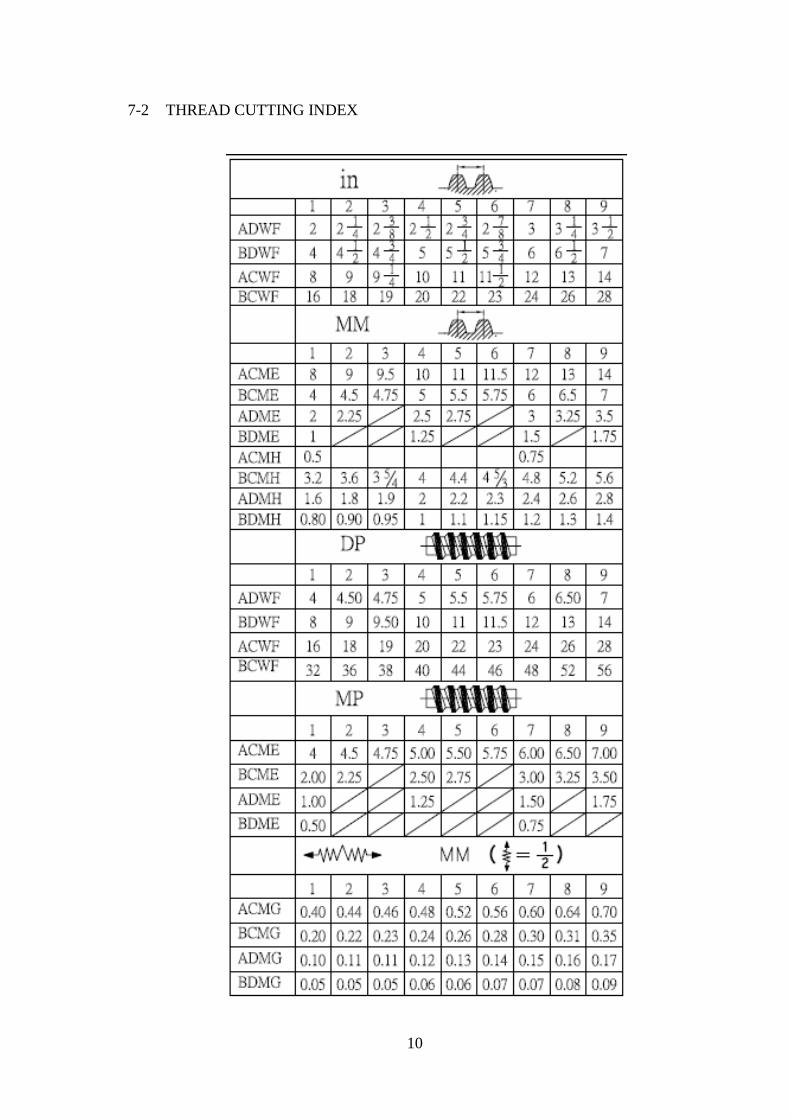
7-2 THREAD CUTTING INDEX

11
7-3 FOUNCTION OF GEARBOX
1. The main function of the gear box is to cutting thread and auto-feed,
full range metric/inch gear box.
2. Operation of thread cutting:
When the thread outing is desired, operate all the speed change lever
and set at proper positions according to the thread cutting index, then
thread outing can be operated to cut the required kind and pitch of thread.
Finally, rotate the feed change lever to “leadscrew” position, then the
operation of thread outing can be proceeded.
3. Operation of automatic feed:
When the operation of automatic feed should be operated, at first operate
all the speed change levers and set at the proper positions according to the
feed speed of requirement (refer to the thread cutting index chart),and then
operate the feed change lever to “feed” position, there upon the operation
of auto feed can be proceeded.
4. Lubrication:
The gear box is lubricated by oil bath lubrication and splash lubrication.
During the machine is running, the oil will be supplied to all bearings and
gears by gears and driving shafts splashed. We can check the oil quantity
through the oil window and fill oil into oil inlet should up to the red line
of oil window in gear box.

12
7-4 THREAD INDICATOR
1. Thread outing indicator is installed on the left side of APRON. It is used
for cutting inch thread.
2. To cut threads of an even number per inch, close the half nut as any line on
the dial pass datum mark.
3. To cut threads of odd numbers per inch close the half nut as any one long
number on the dial passes datum mark.
4. Fractional threads of 1/2 or 3/4 T.P.I. may be by closing the half nut at the
same line on each pass of the tool.
5. This dial indicator can’t be used with an inch lead screw to cut metric
threads, D.P., module pitches. For that will cut the metric threads, the half
nut of APRON must be kept closed ,can only be cut by the spindle reverse-
forward rotation lever in APRON and carriage return is driven by half nut
and lead screw.

13
8. SADDLE AND APRON CONTROL
8-1 LAYOUT OF APRON
1. SQUARE TOOL HODLE
2. TOP-SLIDE
3. CROSS-SLIDE HANDWHEEL
4. SADDLE CASTING
5. APRON CASTING
6. LEVER FOR THREADING
7. LEVER FOR RAPID FEED
8. LEVER FOR AUTO-FEED
9. LONGITUDINAL FEED OF HANDWHEEL
10. THIS LEVER IS DREW OUT FOR LOCATION FIXED OF CROSS (X-AXIS)
AUTO-FEED AND PUSHED FOR LOCATION FIXED OF LONGITUDINAL (Z-AXIS)
AUTO-FEED
11. LEVER TO LUBRICATE MANUALLY
12. LEVER FOR AUTOMATIC LUBRICATION
13. HOLD FOR LUBRICATING
14. LEVER FOR ADJUSTING THE FEEDS
15. LEVER FOR SPINDLE FORWARD AND REVERSE

14
8-2 OPERATION MENTHOD
1. CUTTING OF PLANE
When the longitudinal feed will be moved large in the plane outing.
In order to avoid the carriage back ware and unbalance of cutting plate,
so that there is a look bolt “ D” on the carriage, and fast on it tightly
can increase the stability of compound rest to obtain the plane cutting
in accurate value.
2. CUTTING OF TAPERED PLANE
There are many graduated divisions on the slice plate of carriage. For
the cutting tapered-plane, please loose the locking screw “ B” first, then
rotate the compound rest according to the required angle. After the
adjustment had finished, fasten the setting screw again, then the cutting of
tapered plane can be proceeded.
3. ADJUSTMENT OF BEVEL-GIB
Owing to the friction of long time relative motion between saddle and
cross slide, there will be wear produced. In order to eliminate the excess
clearance, the Bevel-Gib should be adjusted. Its adjusting method:
Loose the set screw in the end of gib first, and fasten the adjusting screw
A, then the gib will be pushed forward to proper position that the clearance
between saddle and cross slide is adequate. Then fasten the setting screw again.
4. CRADUATED COLLER ( MICROMETER COLLAR )
There are the graduated collars (dial) on the longitudinal feed and cross feed
handle. There are 250 scales on the dials; each division means 0.02mm, 5mm for
one revolution. When the zero will be return, please loose the setting screw first.
After the adjustment had finished, fasten the setting screw again.
5. LUBRICATION OF CARRIAGE
The oiling inlets are installed on the carriage and cross slide. Before the
operating, in order to eliminate the wear, it must hand oiling usually.
Lubricate the sliding surface from the oil inlet on carriage by oil gun.

15
6. AUTOMATIC FEED TRANSMISSION
The auto-feed transmission of apron include cross feed and longitudinal
feed. According to the index plate, when you pull the auto feed lever
upward, the carriage with apron can be moved to perform the longitudinal
feeding. When you pull this lever to downward position, the tool –rest with
cross slide can be moved to perform the cross feeding. The step device
installed in the under side of auto –feed lever and it is used for stopping the
auto-feeding. When you make use of this stop device, loose the setting screw
of stop block first, then move stop block to proper position, and then fasten it.
7. TRANS MISSION OF THREAD CUTTING
Only as the automatic feed lever at the central position, the half nut control lever
can be put out downward position, and the half nut engage with the lead screw,
then the carriage can be moved leftward or right –ward to perform the thread
cutting. To stop thread cutting by push up the half nut lever only to release the
engagement of half –nut with lead screw. The safety bar installed in the apron to
keep the thread cutting and auto feed from simultaneous operation to attain the
purpose of safety.
8. FORWARD –REVERSE CHANCE LEVER
The forward –reverse change lever is installed at the right side of apron.
It couple on the starting rod, so that the cutting and feeding work can be
operated conveniently. When you pull this lever right and upward, the spindle
will rotate in reverse direction. When you pull this lever right and downward
the spindle will rotate in forward direction. When this lever at central position,
the spindle will stop.
16
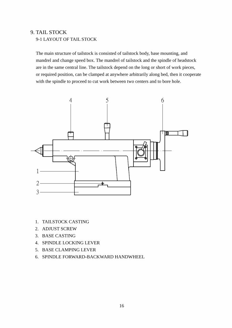
9. TAIL STOCK
9-1 LAYOUT OF TAIL STOCK
The main structure of tailstock is consisted of tailstock body, base mounting, and
mandrel and change speed box. The mandrel of tailstock and the spindle of headstock
are in the same central line. The tailstock depend on the long or short of work pieces,
or required position, can be clamped at anywhere arbitrarily along bed, then it cooperate
with the spindle to proceed to cut work between two centers and to bore hole.
1. TAILSTOCK CASTING
2. ADJUST SCREW
3. BASE CASTING
4. SPINDLE LOCKING LEVER
5. BASE CLAMPING LEVER
6. SPINDLE FORWARD-BACKWARD HANDWHEEL

17
9-2 OPERATIONAL METHOD
1. When the tailstock mandrel and spindle center are not in the same central
line, loose the adjusting screws “2” in the both side, adjust the tailstock
center until its central line is same as spindle, then fasten both adjusting
screw “2”. Use the same method, adjust the tailstock central line to set up
a deviation measure with the spindle and provide for the taper cutting
between two centers.
2. Lubrication of tailstock: tailstock is lubricated by oil bath lubrication system
and its mandrel, center and slide parts must hand oiling from time to time.
10. BRAKE DEVICE
1. Use foot to tread upon the pedal is adopted for the brake mode of this machine.
When the stopping of machine operation is necessary .a momentary force applied
to the foot-brake pedal after can stop the spindle running immediately; and it
had been touched the limited switch to cut off the power source of motor.

18
11. ELECTRICAL CIRCUIT DIAGRAM

19

20

21
12. IDENTIFICATION SYMBOLS
1 Feed
disengaged
15
min
r.p.m.
2 Feed
engaged
16 Half-nut
disengaged
3 Lead screw
forward
17
Half-nut
engaged
4 Lead screw
reverse
18 Main switch
5
Feeding 19
Coolant
switch
6 Threading 20
Pilot lamp
7 High speed 21
JOG button
8 Low speed 22 Electrical
control box
9 Longitudinal
feed
23
Don’t change
over while
rotation
10
Cross feed 24 Main spindle
forward
11
Metric thread 25
Main spindle
stop
12
Inch thread 26
Main spindle
reverse
13 π /
D.P. Screw 27
Clutch
14 π
Modular
screw
28
Stepless
pressure

22
13-1 HEADSTOCK DRIVING STRUCURE

23
13-2 HEADSTOCK SPEED CHANGE STRUCURE

24
13-3 SADDLE AND CROSS –SLIDE STRUCURE
25
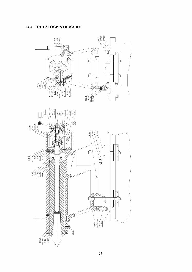
13-4 TAILSTOCK STRUCURE

26
13-5 MOTOR AND END GEARS STRUCURE

27
14 PARTS LIST
14-1 HEADSTOCK EX01
28
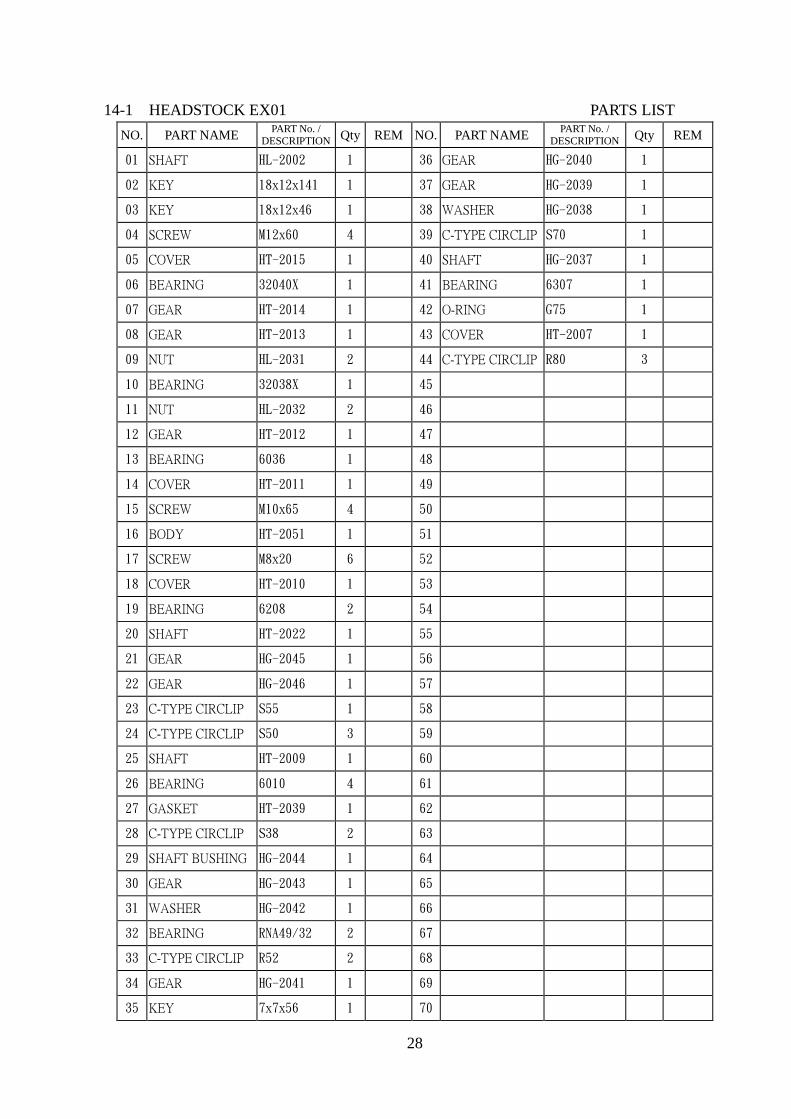
14-1 HEADSTOCK EX01 PARTS LIST
NO. PART NAME PART No. /
DESCRIPTION Qty REM NO. PART NAME PART No. /
DESCRIPTION Qty REM
01 SHAFT HL-2002 1 36 GEAR HG-2040 1
02 KEY 18x12x141 1 37 GEAR HG-2039 1
03 KEY 18x12x46 1 38 WASHER HG-2038 1
04 SCREW M12x60 4 39 C-TYPE CIRCLIP S70 1
05 COVER HT-2015 1 40 SHAFT HG-2037 1
06 BEARING 32040X 1 41 BEARING 6307 1
07 GEAR HT-2014 1 42 O-RING G75 1
08 GEAR HT-2013 1 43 COVER HT-2007 1
09 NUT HL-2031 2 44 C-TYPE CIRCLIP R80 3
10 BEARING 32038X 1 45
11 NUT HL-2032 2 46
12 GEAR HT-2012 1 47
13 BEARING 6036 1 48
14 COVER HT-2011 1 49
15 SCREW M10x65 4 50
16 BODY HT-2051 1 51
17 SCREW M8x20 6 52
18 COVER HT-2010 1 53
19 BEARING 6208 2 54
20 SHAFT HT-2022 1 55
21 GEAR HG-2045 1 56
22 GEAR HG-2046 1 57
23 C-TYPE CIRCLIP S55 1 58
24 C-TYPE CIRCLIP S50 3 59
25 SHAFT HT-2009 1 60
26 BEARING 6010 4 61
27 GASKET HT-2039 1 62
28 C-TYPE CIRCLIP S38 2 63
29 SHAFT BUSHING HG-2044 1 64
30 GEAR HG-2043 1 65
31 WASHER HG-2042 1 66
32 BEARING RNA49/32 2 67
33 C-TYPE CIRCLIP R52 2 68
34 GEAR HG-2041 1 69
35 KEY 7x7x56 1 70

29
14-2 HEADSTOCK EX02

30
14-2 HEADSTOCK EX02 PARTS LIST
NO. PART NAME PART No. /
DESCRIPTION Qty REM NO. PART NAME
PART No. /
DESCRIPTION Qty REM
01 NUT YSR30x1.5 1 36 O-RING G70 1
02 WASHER HT-2030 1 37 GEAR HT-2018 1
03 BELT PULLEY HT-2003 1 38 GEAR HG-2052 1
04 CLUTCH CDI020AA 1 39 SHAFT HT-2019 1
05 GASKET HT-2037 1 40 C-TYPE CIRCLIP S30 1
06 SHAFT HT-2004 1 41 BALL STEEL ψ8 3
07 KEY 12x8x60 1 42 SET SCREW M8x15 3
08 BEARING 6208 2 43 SCREW M6x60 3
09 OIL SEAL 40x62x11 1 44 O-RING G70 1
10 SCREW M8x25 4 45 SCREW M5x12 4
11 COVER HT-2005 1 46
12 O-RING G75 1 47
13 SPACER RING HT-2035 1 48
14 C-TYPE CIRCLIP S40 1 49
15 GEAR HG-2029 1 50
16 KEY 7x7x25 3 51
17 GEAR HG-2030 1 52
18 C-TYPE CIRCLIP S52 1 53
19 SPACER RING HG-2033 1 54
20 BEARING 6006 2 55
21 GEAR HG-2031 1 56
22 GEAR HG-2032 1 57
23 SPACER RING HG-2034 1 58
24 BEARING 6205 4 59
25 PUMP BASE HT-2006 1 60
26 PUMP AM2A 1 61
27 BEARING 6206 2 62
28 SCREW M8x30 3 63
29 COVER HG-2051 1 64
30 OIL SEAL 30x50x10 1 65
31 SHAFT HT-2021 1 66
32 KEY 8x7x25 1 67
33 GEAR HT-2030 1 68
34 SCREW M8x20 3 69
35 COVER HT-2017 1 70

31
14-3 HEADSTOCK EX03

32
14-3 HEADSTOCK EX03 PARTS LIST
NO. PART NAME PART No. /
DESCRIPTION Qty REM NO. PART NAME PART No. /
DESCRIPTION Qty REM
01 SCREW M12x55 8 36 SHAFT HT-2031 2
02 COVER HL-2003 1 37 O-RING G70 4
03 HANDLE HG-2054 3 38 BUSHING HG-2057 1
04 STEM ARM HG-2055 3 39 FORK ARM HT-2026 1
05 BUSHING HG-2057 1 40 BUSHING HG-2057 1 輸入軸
06 SCREW M6x16 8 41 FORK HT-2025 1
07 SHAFT HG-2056 3 42 COVER HT-2033 3
08 O-RING P21 10 43 SET RING HT-2034 4
09 GEAR HG-2058 2 44 SCREW M6x12 9
10 O-RING G35 5 45 SHAFT HT-2032 1
11 SHAFT SLEEVE HT-2042 2 46 FORK HT-2036 1
12 GEAR HT-2041 2 47 SET SCREW M6x6 4
13 SHAFT HT-2024 2 48 PIN ψ5x80 3
14 KEY 6x6x25 1 49 SPRING PIN ψ5x12 3
15 FORK ARM HT-2050 2 50 BALL STEEL ψ6 1
16 FORK HG-2062 4 51 SPRING ψ6x15 1
17 FORK HT-2028 1 52 SCREW M8x8 1
18 SHAFT SLEEVE HG-2059 1 53
19 FORK ARM HT-2027 1 54
20 O-RING P16 2 55
21 SHAFT HT-2029 1 56
22 KEY 6x6x30 2 57
23 FORK ARM HG-2061 1 58
24 HANDLE HG-256 1 59
25 STEM ARM HG-2070 1 60
26 BUSHING HG-2071 1 61
27 FORK ARM HG-2072 1 62
28 FORK HT-2023 1 63
29 SCREW M8x16 4 64
30 PRESS BLOCK HG-2050 4 65
31 SHAFT HT-2016 1 66
32 BEARING 6005 2 67
33 C-TYPE CIRCLIP R47 2 68
34 GEAR HG-2049 1 69
35 C-TYPE CIRCLIP S30 1 70

33
14-4 SADDLE AND CROSS – SLIDE EX04

34
14-4 SADDLE AND CROSS – SLIDE EX04 PARTS LIST
NO. PART NAME PART No. /
DESCRIPTION Qty REM NO. PART NAME PART No. /
DESCRIPTION Qty REM
01 LOCK PLATE HT-5009 1 36 PRESS PLATE HT-5015 2
02 SCREW M12x30 4 37 WIPER HT-5011 2
03 FIXED PLATE HT-5008 1 38 PRESS PLATE HT-5012 2
04 SCREW M12x45 4 39 LOCK PLATE HL-5019-1 1
05 FIXED SCREW 1C0043 4 40 船座 HL-6000 1 185
06 PRESS PLATE HT-5007 1 41 SCREW M8x20 1
07 WIPER HL-5026 1 42 WASHER HG-515 1
08 SCREW M5x16 14 43 HANDLE HL-5032 1
09 PLATE HT-5002 1 44 BRACKET HL-5007 1
10 SLIDING HL-5002 1 45 C-TYPE CIRCLIP S25 2
11 STRIP HL-5004b 1 46 GEAR HT-5004 1
12 SCREW M16x40 4 47 SET SCREW M6x25 1
13 GRADUATON BED HT-5016 1 860 48 SHAFT HT-5005 1
14 SCREW M5x10 4 49 BUSHING HL-5005 1
15 SET SCREW PT1/8 1 50 SET SCREW M10x10 1
16 SCREW M12x55 3 51 SPRING ø8x20 1
17 COVER HL-5024 1 52 BALL STEEL ø8 1
18 SCREW M12x40 4 53 NUT AN05 2
19 WIPER 8C0384 1 54 WASHER AW05 1
20 BEARING 51105 2 55 INDEX RING HL-5006I 1 英制
21 KEY 4x4x16 1 56 SCREW M10x90 4
22 LEAD SCREW HT-5006 1 57 WASHER HL-5017 1
23 KEY 6x6x25 1 58 NUT HL-5023 4
24 NUT HL-5010I 1 英制 59 CARRIAGE HT-5001 1
25 LOCK PLATE HL-5016 1 60 SCREW M6x12 2
26 SCREW M16x115 1 61
27 C-TYPE CIRCLIP S28 1 62
28 GEAR HT-5003 1 63
29 OIL SEAL 30x42x8 1 64
30 BEARING RNA4905 1 65
31 BEARING 6004 1 66
32 OIL COVER TC20x32x8 1 67
33 BRACKET HL-5013 1 68
34 SCREW M8x15 2 69
35 WIPER HT-5014 2 70

35
14-5 TAILSTOCK ASSEMBLY EX05
36
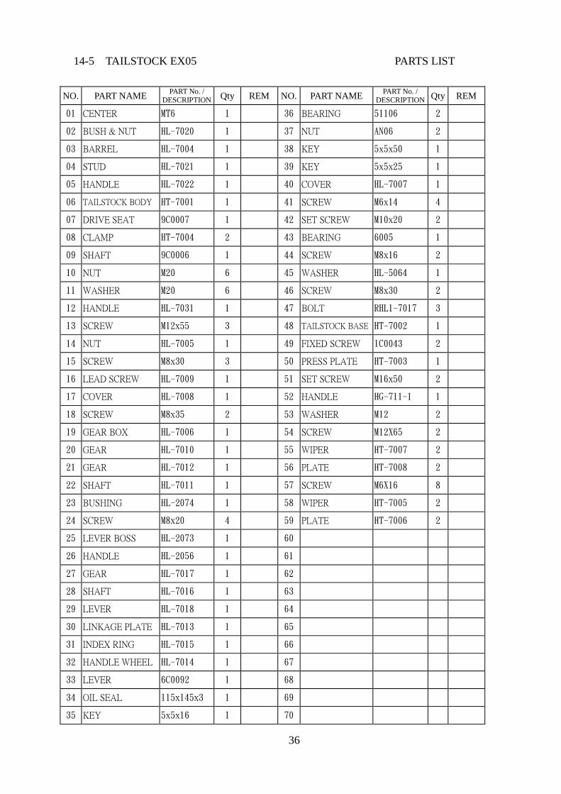
14-5 TAILSTOCK EX05 PARTS LIST
NO. PART NAME PART No. /
DESCRIPTION Qty REM NO. PART NAME PART No. /
DESCRIPTION Qty REM
01 CENTER MT6 1 36 BEARING 51106 2
02 BUSH & NUT HL-7020 1 37 NUT AN06 2
03 BARREL HL-7004 1 38 KEY 5x5x50 1
04 STUD HL-7021 1 39 KEY 5x5x25 1
05 HANDLE HL-7022 1 40 COVER HL-7007 1
06 TAILSTOCK BODY HT-7001 1 41 SCREW M6x14 4
07 DRIVE SEAT 9C0007 1 42 SET SCREW M10x20 2
08 CLAMP HT-7004 2 43 BEARING 6005 1
09 SHAFT 9C0006 1 44 SCREW M8x16 2
10 NUT M20 6 45 WASHER HL-5064 1
11 WASHER M20 6 46 SCREW M8x30 2
12 HANDLE HL-7031 1 47 BOLT RHL1-7017 3
13 SCREW M12x55 3 48 TAILSTOCK BASE HT-7002 1
14 NUT HL-7005 1 49 FIXED SCREW 1C0043 2
15 SCREW M8x30 3 50 PRESS PLATE HT-7003 1
16 LEAD SCREW HL-7009 1 51 SET SCREW M16x50 2
17 COVER HL-7008 1 52 HANDLE HG-711-1 1
18 SCREW M8x35 2 53 WASHER M12 2
19 GEAR BOX HL-7006 1 54 SCREW M12X65 2
20 GEAR HL-7010 1 55 WIPER HT-7007 2
21 GEAR HL-7012 1 56 PLATE HT-7008 2
22 SHAFT HL-7011 1 57 SCREW M6X16 8
23 BUSHING HL-2074 1 58 WIPER HT-7005 2
24 SCREW M8x20 4 59 PLATE HT-7006 2
25 LEVER BOSS HL-2073 1 60
26 HANDLE HL-2056 1 61
27 GEAR HL-7017 1 62
28 SHAFT HL-7016 1 63
29 LEVER HL-7018 1 64
30 LINKAGE PLATE HL-7013 1 65
31 INDEX RING HL-7015 1 66
32 HANDLE WHEEL HL-7014 1 67
33 LEVER 6C0092 1 68
34 OIL SEAL 115x145x3 1 69
35 KEY 5x5x16 1 70
37
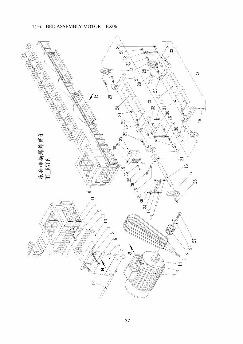
14-6 BED ASSEMBLY-MOTOR EX06

38
14-6 BED ASSEMBLY-MOTOR EX06 PARTS LIST
NO. PART NAME PART No. /
DESCRIPTION Qty REM NO. PART NAME PART No. /
DESCRIPTION Qty REM
01 V-BELT B-84 4 36 WASHER M4 2
02 PULLEY HL-1019 1 37 NUT M4 2
03 MOTOR 20HP-4P 1 38 SCREW M6x12 2
04 SCREW M12x45 4 39
05 NUT M16 4 40
06 WASHER M16 8 41
07 MOTOR PLATE HL-1015-2 1 42
08 BLOT HL-1018 2 43
09 SCREW M16x50 4 44
10 BED HT-1001 1 45
11 LOW-PLATE HL-1016A 2 46
12 SHAFT HL-1017 2 47
13 SET SCREW M8x16 4 48
14 KEY #12x80 1 49
15 SCREW M10x35 6 50
16 BRAKE ROD HT-1008 1 51
17 BRACKET HG-108-2 1 52
18 SPRING LG-1062 3 53
19 LIMIT SWITCH AM-1701 1 SOLON 54
20 BRACKET HT-1010 1 55
21 BRAKE CONTROL
WHELL HG-112 1 56
22 FIXED BLOCK HG-108 4 57
23 FIXED PLATE HG-118-1 4 58
24 BRAKE PEDAL HT-1006 2 59
25 SCREW M8x20 2 60
26 NUT M8 15 61
27 SCREW M12x30 1 62
28 WASHER M12 1 63
29 SCREW M8x25 16 64
30 SCREW M8x35 6 65
31 NUT M6 16 66
32 BRAKE PEDAL HT-1006 2 67
33 BRAKE LEVER LG-1016 4 68
34 WASHER M10 1 69
35 SCREW M4x40 2 70
39
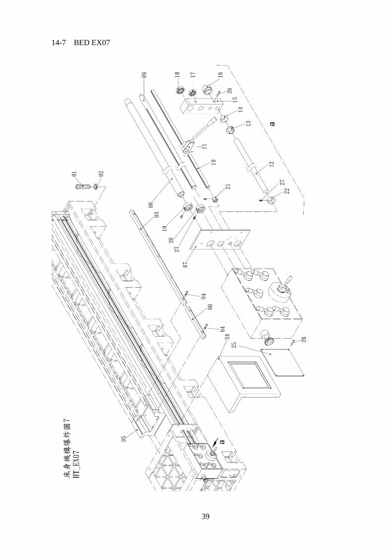
14-7 BED EX07

40
14-7 BED EX07 PARTS LIST
NO. PART NAME PART No. /
DESCRIPTION Qty REM NO. PART NAME PART No. /
DESCRIPTION Qty REM
01 SCREW 1-12UNF 8 33
02 NUT 1-12UNF 8 34
03 RACK HG-529 4 1060 35
04 SCREW M8x15 25 36
05 GAP BED HT-1016 1 37
06 RACK HG-532-1 1 188 38
07 COVER PLATE HG-130 1 39
08 LEAD SCREW HT-1002 1 40
09 FEED ROD HT-1003 1 41
10 SWITCH ROD HT-1004 1 42
11 START LEVER 1 床裙附件 43
12 4th ROD HT-1005 1 44
13 ECCENTRIC
BLOCK HG-1803 6 45
14 CHIP-PROOF
WASHER HG-1802 1 46
15 BRACKET HG-182 1 47
16 POSITION
INDEXING RING HG-1818 1 48
17 BEARING 6303 1 49
18 BEARING 6205 1 50
19 CHIP-PROOF
WASHER HG-132-1 1 51
20 CHIP-PROOF
WASHER HG-133-1 1 52
21 CHIP-PROOF
WASHER HG-134-1 1 53
22 CHIP-PROOF
WASHER HG-133-1 1 54
23 SCREW M12x85 2 55
24 COVER HT-1012 1 56
25 COVER PLATE HT-1020 1 57
26 SCREW M5x20 6 58
27 SET SCREW M6x10 4 59
28 SET SCREW M8x10 7 60
29 RACK HG-532 1 520 61
30 62
31 63
32 64

41
14-8 END GEARS STRUCURE EX08

42
14-8 END GEARS STRUCURE EX08 PARTS LIST
NO. PART NAME PART No. /
DESCRIPTION Qty REM NO. PART NAME PART No. /
DESCRIPTION Qty REM
01 SCREW M8x18 1 36
02 WASHER LG-1021A-1 1 37
03 SHAFT HG-450-5-3 1 38
04 GEAR HG-450-5-3 1 39
05 SCREW M8x28 3 40
06 BRACKET HG-138-1 1 41
07 NUT LG-3212 1 42
08 BEARING 6206 1 43
09 SCREW M8x30 3 44
10 COVER HG-N234 1 45
11 BRACKET HG-138A 1 46
12 SHAFT HG-139A 1 47
13 BEARING 6003Z 2 48
14 GEAR HG-450-5 1 49
15 SHAFT LG-3202 1 50
16 C-TYPE CIRCLIP S25 1 51
17 NUT 5/8-11UNC 1 52
18 BEARING 6005 2 53
19 SCREW M6x20 3 54
20 GEAR HG-181 1 55
21 CONNECTION
COLLAR HG-182 1 56
22 SHAFT HG-140 1 57
23 GEAR HG-183 1 58
24 SHAFT COLLAR HG-140A 1 59
25 SPRING PIN ψ4x16 1 60
26 SPRING WASHER M8 1 61
27 C-TYPE CIRCLIP R37 1 62
28 C-TYPE CIRCLIP S17 1 63
29 SCREW M12x50 1 64
30 WASHER HG-N279-1 1 65
31 66
32 67
33 68
34 69
35 70

43
14-9 GEAR BOX EX09

44
14-9 GEAR BOX EX09 PARTS LIST
No. Description Qty No. Description Qty
1 Gear box 1 48 Bearing 6204 1
2 Bolt M8x25L 1 49 Bearing 6204 3
3 Washer 1 50 Gear 1
4 Gear 1 51 Gear 1
5 Snap ring 1 52 Gear 1
6 Bearing 6006 1 53 Gear 1
7 Bolt M6x50L 3 54 Gear 1
8 Cover 1 55 Gear 1
9 Bearing 6206 1 56 Gear 1
10 Key 6x6x25L 1 57 Gear 1
11 Shaft 1 58 Gear 1
12 Key 6x6x50L 1 59 Gear 1
13 Gear 1 60 Shaft 1
14 Gear 1 61 Key 6x6x130L 1
15 Snap ring 1 62 Bearing 6204 1
16 Bearing 6203 1 63 Bearing 6204 1
17 Gear 1 64 Gear 1
18 Bearing 6205 1 65 Gear 1
19 Key 6x6x20L 1 66 Gear 1
20 Shaft 1 67 Key 6x6x70L 1
21 Key 6x6x50L 1 68 Shaft 1
22 Key 6x6x20L 1 69 Bearing 6204 1
23 Bearing 6005 1 70 Cover 1
24 Gear 1 71 Bolt M6x16L 3
25 Snap ring 1 72 Bolt M6x16L 3
26 Gear 1 73 Cover 1
27 Snap ring 1 74 Bearing 6204 1
28 Bearing 6006 1 75 Shaft 1
29 Clutch 1 76 Key 6x6x20L 1
30 Bearing 6002 1 77 Gear 1
31 Gear 1 78 Snap ring 1
32 Nut 2 79 Bearing 6205 1
33 Washer 1 80 Washer 1
34 Bearing 30206 1 81 Gear 1
35 Bearing 30206 1 82 Gear housing 1
36 Cover 1 83 Bearing 6205 1
37 Bolt M6x25L 1 84 Snap ring 1
38 Shaft 1 85 Gear 1
39 Bolt M6x16L 3 86 Bearing 6002 1
40 Cover 1 87 Clutch 1
41 Bearing 6204 1 88 Bearing 6006 1
42 Gear 1 89 Snap ring 1
43 Snap ring 1 90 Snap ring 1
44 Shaft 1 91 Bearing 6005 1
45 Key 6x6x55L 1 92 Cover 1
46 Key 6x6x55L 1 93 Bolt M6x16L 3
47 Gear 1 94 Shaft 1

45
14-10 APRON EX10

46
14-10 APRON EX10 PARTS LIST
No. Description Qty No. Description Qty
1 Key 6x6x25L 1 43 Snap ring STW17 1
2 Gear shaft 1 44 Bearing 6003 1
3 Du Bearing DU25/25 1 45 Gear 1
4 Gear 1 46 Collar 1
5 Screw M6x15L 1 47 Shaft 1
6 Cam 1 48 Pin ø3 x 8L 1
7 Bearing 6203 1 49 Sleeve 1
8 Set screw M6x12L 1 50 Bolt M6x20L 2
9 Pump rod 1 51 Regulator 1
10 Pump stand 1 52 Bracket 1
11 Snap ring P19 1 53 Sleeve 1
12 Pin ø4 x 18L 1 54 Set screw M6x12L 2
13 Pin ø5 x 14L 1 55 Apron casting 1
14 Shaft 1 56 Sleeve 1
15 Bushing 1 57 Cover 1
16 Bolt M8x15L 2 58 Shaft 1
17 Name plate 1 59 Swing arm 1
18 Bolt M5x12L 1 60 Nut 1
19 Bearing 6203 1 61 Bolt M5x12L 1
20 Gear shaft 1 62 Bolt M8x15L 1
21 Key 5x5x20L 1 63 Oil seal TC16307 1
22 Bearing 6203 1 64 Bearing housing 1
23 Bushing 1 65 Handle 1
24 Bolt M6x30L 3 66 Bolt M6x16L 3
25 Index ring 1 67 Hub 1
26 Handwheel 1 68 Pin ø5 x40L 1
27 Bracket 1 69 Snap ring STW17 1
28 Bolt 5/16"x1" 1 70 Bearing 6203 1
29 Snap ring STW17 1 71 worm 1
30 Bearing 6003 1 72 Gear 1
31 Gear 1 73 Spring pin ø4 x8L 1
32 Bearing 6003 1 74 Shaft 1
33 Shaft 1 75 Bearing 6204 1
34 Stud 1 76 Bushing 1
35 Shaft housing 1 77 Bolt M6x16L 3
36 Set screw 1/4" 1 78 Name plate 1
37 Handle 1 79 Bolt M10x30L 1
38 Bolt M6x16L 3 80 Bolt M6x16L 3
39 Name plate 1 81 Shaft 1
40 Handle 1 82 Key 6x6x20L 1
41 Bolt M8x25L 1 83 Gear 1
42 Nut M8 1 84 Bushing 2

47
14-10 APRON EX10 PARTS LIST
No. Description Qty No. Description Qty
85 Oil seal TC40528 2 124 Gear 1
86 Shaft 1 125 Snap ring S12 1
87 Bearing 51104 2 126 Shaft 1
88 Du Bearing 2 127 Spring 1
89 Worm 1 128 Shaft 1
90 Bolt M6x16L 1 129 Oil seal 13246 1
91 Swing arm 1 130 top cover 2
92 Bracket 1 131 pinion gear 1
93 Washer AN04 1 132 Rapid motor 1/4HP 1
94 Nut AN04 1
95 Cover 1
96 Bolt M6x16L 4
97 Bracket 1
98 Pin ø10x30L 1
99 Swing arm 1
100 Bolt M6x8L 1
101 Pin ø5x14L 1
102 Stud 1
103 Oil seal 1
104 Nut M6 1
105 Bolt M6x20L 1
106 Bolt M6x16L 2
107 Pin ø5/16"x16L 2
108 Shaft 1
109 Bolt M6x20L 2
110 Swing block 1
111 Pin ø5x40L 1
112 Handle 1
113 Hub 1

48
14-11 APRON EX11 PARTS LIST (WITH RAPED FEED)

49
14-11 APRON EX11 PARTS LIST (WITH RAPED FEED)
No. Description Qty No. Description Qty
1 Oil seal 40528 1 43 Shaft 1
2 Bushing 1 44 Screw M6x16L 2
3 Shaft 1 45 Rack 1
4 Key 6x6x20L 1 46 Pin 1
5 Gear 1 47 Shaft 1
6 Bushing 1 48 Shaft 1
7 Oil seal 40528 3 49 Bracket 1
8 Nut AN03 1 50 Shaft 1
9 Bearing 51103 1 51 Bearing 6003 1
10 Bearing 51103 1 52 Snap ring S40 1
11 Worm 1 53 Gear 1
12 Bushing 1 54 Gear 1
13 Gear 1 55 Bearing 6003 1
14 Screw M6x16L 2 56 Gear 1
15 Rack 1 57 Cover 1
16 Bracket 1 58 Cover 1
17 Shaft 1 59 Screw M6 x 35L 2
18 Shaft 1 60 Hub 1
19 Bracket 1 61 Handle 1
20 Bearing 51103 1 62 Shaft 1
21 Spring 1 63 Bracket 1
22 Gear 1 64 Screw M12x35L 1
23 Pin ø3 x 8L 4 65 Bracket 1
24 Sleeve 1 66 Shaft 1
25 Screw M6x20L 2 67 Snap ring S16 1
26 Regulator 1 68 Shaft 1
27 Bracket 1 69 Key 5x5x10L 1
28 Sleeve 1 70 Lever 1
29 Apron Box 1 71 Lever 1
30 Screw M6x16L 2 72 Cover 1
31 Cover 1 73 Screw M6x16L 3
32 Shaft 1 74 Handle 1
33 Bearing 51103 1 75 Hub 1
34 Gear 1 76 Pin 1
35 Spring 1 77 Bearing 6203 1
36 Gear 1 78 Gear 1
37 Bearing 6003 1 79 Gear 1
38 Gear 1 80 Bearing 6203 1
39 Cover 1 81 Shaft 1
40 Screw M6x16L 2 82 Snap ring S17 1
41 Cover 1 83 Bearing 6003 1
42 Bracket 1 84 Gear 1

50
14-11 APRON EX11 PARTS LIST (WITH RAPED FEED)
No. Description Qty No. Description Qty
85 Bearing 6203 1 123 Cover 1
86 Shaft 1 124 Gear 1
87 Snap ring S17 1 125 Snap ring S12 1
88 Bearing 6003 1 126 Shaft 1
89 Gear 1 127 Spring 1
90 Bearing 6003 1 128 Shaft 1
91 Snap ring S20 1 129 Oil seal 13246 1
92 Shaft 1 130 top cover 2
92-1 Bushing 1 131 pinion gear 1
93 Handle 1 132 Rapid motor 1/4HP 1
94 Bearing 6003 1
95 Gear 1
96 Snap ring R35 1
97 Bearing 6003 1
98 Washer 1
99 Gear 1
100 Bearing 6003 1
101 Shaft 1
102 Bearing 6203 1
103 Gear shaft 1
104 Bearing 6005 1
105 Cover 1
106 Screw M6x16L 3
107 Clutch 1
108 Clutch 1
109 Index ring 1
110 Handwheel 1
111 Handle 1
112 Shaft 1
113 Bracket 1
114 Screw M12x30L 1
115 Gear shaft 1
116 Key 8x8x30L 1
117 Gear 1
118 Screw M6x12L 1
118-1 Collar
119 Bearing 6203 1
120 Pin 1
121 Shaft 1
122 Handle 1