HEAVY DUTY MORTISE LOCKS - Dh Pace DUTY MORTISE LOCKS ... Lever return spring mechanism located in...
20
HEAVY DUTY MORTISE LOCKS Distributed By DH Pace National Key Service Center 855-237-3667 [email protected] DHPace.com/BestSolutions
Transcript of HEAVY DUTY MORTISE LOCKS - Dh Pace DUTY MORTISE LOCKS ... Lever return spring mechanism located in...

HEAVY DUTY MORTISE LOCKS
��
��
��
��
��
��
��
��
Distributed ByDH Pace National Key Service Center
[email protected]/BestSolutions
40H
ExPLODED6
11
13
10
2 H E AV Y D U T Y M
FEATURES
FEA
TU
RES
1
Page
40H
CUTAWAY
TA
BLE O
F
CO
nTEn
TS
2
4
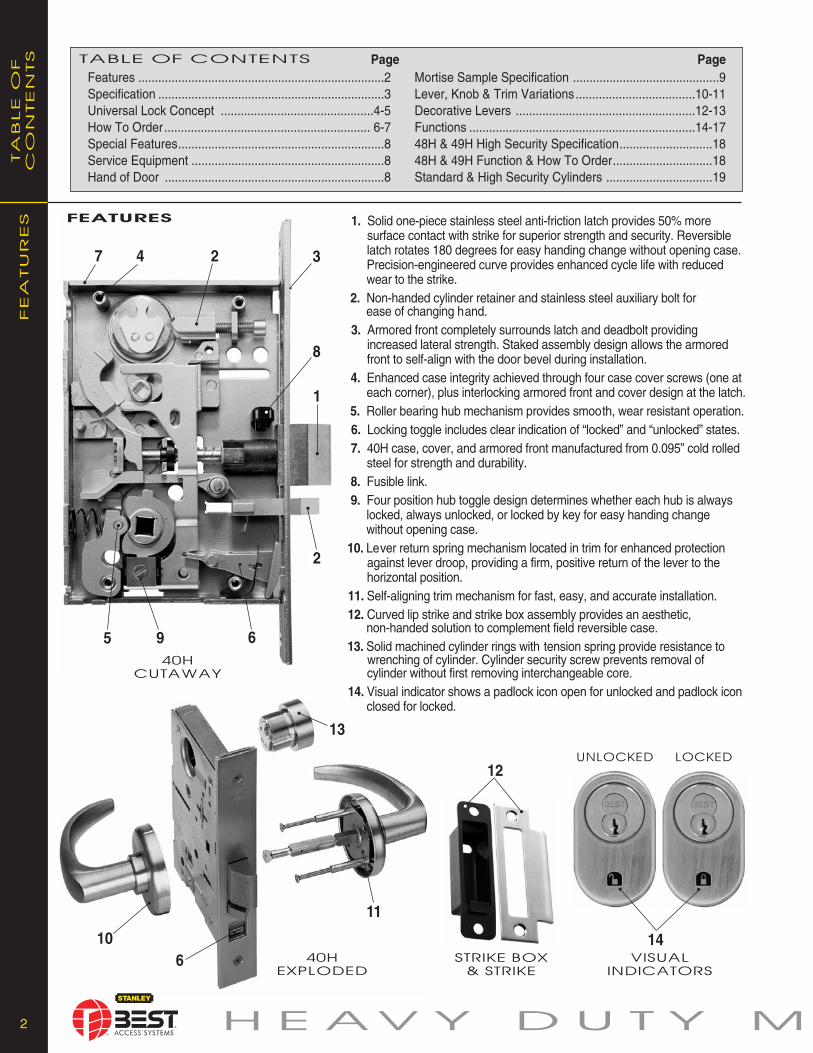
1. Solid one-piece stainless steel anti-friction latch provides 50% more surface contact with strike for superior strength and security. Reversible latch rotates 180 degrees for easy handing change without opening case. Precision-engineered curve provides enhanced cycle life with reduced wear to the strike.2. Non-handed cylinder retainer and stainless steel auxiliary bolt for ease of changing hand.3. Armored front completely surrounds latch and deadbolt providing increased lateral strength. Staked assembly design allows the armored front to self-align with the door bevel during installation. 4. Enhanced case integrity achieved through four case cover screws (one at each corner), plus interlocking armored front and cover design at the latch.5. Roller bearing hub mechanism provides smooth, wear resistant operation.6. Locking toggle includes clear indication of “locked” and “unlocked” states.7. 40H case, cover, and armored front manufactured from 0.095” cold rolled steel for strength and durability.8. Fusible link.9. Four position hub toggle design determines whether each hub is always locked, always unlocked, or locked by key for easy handing change without opening case.10. Lever return spring mechanism located in trim for enhanced protection against lever droop, providing a firm, positive return of the lever to the horizontal position.11. Self-aligning trim mechanism for fast, easy, and accurate installation.12. Curved lip strike and strike box assembly provides an aesthetic, non-handed solution to complement field reversible case.13. Solid machined cylinder rings with tension spring provide resistance to wrenching of cylinder. Cylinder security screw prevents removal of cylinder without first removing interchangeable core.14. Visual indicator shows a padlock icon open for unlocked and padlock icon closed for locked.
STRIKE BOx
& STRIKE
5 9 6
2
8
12
7 3
Features ..........................................................................2 Specification ....................................................................3 Universal Lock Concept ..............................................4-5 How To Order.............................................................. 6-7 Special Features..............................................................8 Service Equipment ..........................................................8 Hand of Door ..................................................................8
TABLE OF COnTEnTS PageMortise Sample Specification ............................................9Lever, Knob & Trim Variations....................................10-11Decorative Levers ......................................................12-13 Functions ....................................................................14-1748H & 49H High Security Specification............................1848H & 49H Function & How To Order..............................18Standard & High Security Cylinders ................................19
VISUAL
InDICATORS
UnLOCKED LOCKED
14

3 O R T I S E L O C K S
ADA-Americans With Disabilities Act:45H Series - The design and operation of the BEST® mortise lock meets the intent of the standard for ANSI A117.1 section 404.2.6.
Builders Hardware Manufacturers Association:45H Series - ANSI A156.13, Series 1000, Grade 1 Operation and Strength, Grade 2 Security. To meet Grade 1 Security, a drill resistant core (1CD, 1CDP, 1CDF, or 1CDX) must be used with escutcheon trims, and 1E7K4 high security cylinder must be used with sectional trims.
47H Series - ANSI A156.13, Series 1000, Grade 1 Operational, Strength, and Security.
Underwriters Laboratories®
The 40H series is listed by Underwriters Laboratories for use on a 3 hour A label doors. These locks also carry the C-UL mark which is officially accepted in all of Canada, indicating compliance with appropriate Canadian standards and codes. The 47H series locks conform to UL437 standard for key locks, referencing door locks. The 1E7J4 cylinder used in the 47H series also conforms to UL437 standard for key locks, referencing high security cyl in ders, and is listed for Canada as well as the United States.
Florida Building Code (FBC) Listed and Miami-DadeCounty Code Compliance Office For “AB” function 40H series lock is certified for use in applications requiring a design pressure rating as specified.
Description Single Door Double DoorPSF w/o DeadBolt +-60 +-35PSF w/ DeadBolt +-100 +-50
The 40H series lock has received a notice of acceptance from Miami-Dade County and is considered Miami-Dade County product control approved.
Auxiliary bolt: Stainless steel, non-handed.
Backset: 2 3/4"
Case: 0.095" cold rolled steel, 5 7/8" H x 7/8" D x 4 1/16" W. Steel is zinc dichromate plated for corrosion protection.
Deadbolt: Stainless steel, 1" throw.
Door Thickness: Standard lock configuration designed for doors 1 3/4" thick. Thick door configuration available for doors up to 5" thick (specify thickness when ordering).
Escutcheons: J – Wrought brass, bronze, or stainless steel base material, 7 1/2" H x 2 9/32" W x 17/32" T. M & N – Forged brass or bronze, 8" H x 2 1/8" W x 37/64" T, through bolt mounted (no exposed screws outside). M – Standard cylinder; N – Concealed cylinder.
Faceplate: Brass or bronze material, 8" H x 1 1/4" W x 1/16" T. Lock face automatically adjusts to proper bevel during installation.
Products protected by one or more of the following patents: 4,873,853 5,590,555 5,794,472
Finishes:• 605 – bright brass, clear coated• 606 – satin brass, clear coated• 611 – bright bronze, clear coated• 612 – satin bronze, clear coated• 613* – oxidized satin bronze, oil rubbed• 618 – bright nickel plated, clear coated (brass base material)• 619 – satin nickel plated, clear coated (brass base material)• 622 – flat black coated (brass base material)• 625 – bright chromium plated (brass base material)• 626 – satin chromium plated (brass base material)• 629 – bright stainless steel• 630 – satin stainless steel• 690* – dark bronze coated (brass base material)
* 613 finish is designed to wear over time, providing an “antique” appearance. 690 finish will continue as a dark brown appearance over time.
Antimicrobial Finish• 626AM – satin chrome plated with
UltraShield™ antimicrobial protected coating• 630AM – satin stainless steel with UltraShield™ antimicrobialprotected coating
The Stanley Security Solutions UltraShield™ finish inhibits the growthof bacteria and other microbes on the surface of the hardware.
Note: Stanley’s UltraShield™ option is recommended for use on any hardware application where product cleanliness is a high priority. i.e;. Hospital/Healthcare, Elderly Care, Education, Transportation, Food-Service, Hospitality.
#4 Knob: Diameter – 2 1/8" ; Projection on door – 2 7/8" Material machined from solid brass or bronze.
Decorative and Special Order Lever Handles: Stainless steel base material with applied finish.
Latchbolt: Solid stainless steel, 3/4" throw. Latch is oil-impregnated for anti-friction operation. Reversible without opening case.
Roses:Wrought brass, bronze, or stainless steel base material. H – Flat w/ round edge, 2 3/4" diameter. R – Contoured w/ round edge, 2 3/4" diameter. S – Flat w/ beveled edge, 3 1/2" diameter.
Standard Lever Handles: Brass, bronze, or stainless steel base material for standard lever designs. Lever styles #3, #14, and #15 return to a minimum of 1/2" of door surface. Lever styles #3 and #14 conform to California Titles 19 and 24. Lever styles 12, 16 and 17 do not return. Levers project 2 15/16" from door surface with H, J, R and S trim. Levers project 3 1/64" with M and N trim.
Strike: For complete strike package spec’s see page 5.
Vandal Trim: VT–Vandal trim is available in standard finish for H, J, M, N, R, and S trims in either #14 or #15 levers. Note: Not available in single or dummy trim functions.If compliance to California Building Code Title 19 & 24 is required, the #14 lever design must be specified.
Visual Indicators: VIN–Visual indication uses an unlocked padlock or locked padlock image with red background to indicate lock state.
SP
EC
IFIC
ATIO
NSSPECIFICATIONS
UltraShield™

44 H E AV Y D U T Y M
Un
IV
ER
SA
L LO
CK
FLEx
IB
ILITY
In
O
RD
ER
In
G
UNIvERSAL LOCK DESIgN CONCEPT
Strength, Durability…and now Flexibility.
Sure, a mortise lock is one of the strongest and longest lasting locks available. But who says it has to be the most complex to order and install? When designing the 40H mortise lock, BEST®
decided to focus on things that would make the lock easier to use, while at the same time maintaining the strength, durability, and dependability you would expect in a BEST®
mortise lock.
In addition to the ability to quickly change the lock handing, the universal case design of the 40H provides the ability to reconfigure a lock into many different functions easily and quickly, often by rearranging existing parts without disassembling the lock case. The efficiency of the design enables over 12 of the most commonly used lock functions to be included in just 3case configurations.
The 40H provides the ability to postpone decisions on how the lock will be configured all the way up to the point of installa-tion, making it one of the most flexible and user-friendly mortise locks available. This translates into value for anyone involved in the process, whether they’re an architect, specification writer, distributor, or end-user.
FLExIbILITy IN ORDERINg
Stanley/BEST offers three ways in which to order the 40H mortise lock. YOU get to choose which method meets your needs.
Function Specific LockIf you know exactly what you need in a mortise lock, and are confident that your needs won’t change, then order your 40H locks in the traditional way by specifying the exact function, trim, finish, and handing. BEST® will build the locks to work exactly as specified, so they may or may not have the ability to be converted to another function in the future.
Universal LockIf you want to keep your options open, this method of ordering the 40H is for you. BEST®
has developed three “universal” functions that can be configured to a variety of commonfunctions, all without opening the lock case.When any of the universal functions are ordered as a complete lock, all the necessaryparts (including trim) are provided to configureany of the functions in that group.
InsideKit
OutsideKit
CaseOnly
StrikePackage
For the maximum flexibility in ordering a mortise lock,BEST® provides a way to order your 40H lock in four parts:Inside Trim, Case Only, Outside Trim and Strike Packages.The kits that make up these four parts have been carefullydesigned so that when all three are combined you haveeverything found in a complete 40H lock. This order methodis ideal for customers wanting to stock a variety of trimdesigns with a minimal number of lock cases.
FOUR-PART LOCK
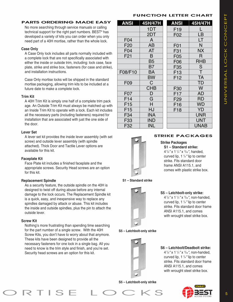
Strike PackagesS1 – Standard strike:47/8" x 1 1/4" x 3/32", handed, curved lip, 1 1/4" lip to center strike. Fits standard door frame ANSI A115.1, and comes with plastic strike box.
S5 – Latchbolt-only strike:47/8" x 1 1/4" x 3/32", non-handed, curved lip, 1 1/4" lip to center strike. Fits standard door frame ANSI A115.1, and comes with wrought steel strike box.
S6 – Latchbolt/Deadbolt strike:47/8" x 1 1/4" x 3/32", non-handed, curved lip, 1 1/4" lip to center strike. Fits standard door frame ANSI A115.1, and comes with wrought steel strike box.
55 O R T I S E L O C K S
PARTS ORDERINg MADE EASy
No more searching through service manuals or calling technical support for the right part numbers. BEST® has developed a variety of kits you can order when you only need part of a 40H mortise, rather than the whole lock.
Case OnlyA Case Only lock includes all parts normally included witha complete lock that are not specifically associated with either the inside or outside trim, including: lock case, faceplate, strike and strike box, fasteners (for case and strike),and installation instructions.
Case Only mortise locks will be shipped in the standard mortise packaging, allowing trim kits to be included at a future date to make a complete lock.
Trim KitA 40H Trim Kit is simply one half of a complete trim package. An Outside Trim Kit must always be matched up withan Inside Trim Kit to operate with a lock. Each kit includesall the necessary parts (including fasteners) required for installation that are associated with just the one side of the door.
Lever SetA lever set kit provides the inside lever assembly (with setscrew) and outside lever assembly (with spindle attached). Thick Door and Tactile Lever options are available for this kit.
Faceplate KitFace Plate kit includes a finished faceplate and the appropriate screws. Security Head screws are an option for this kit.
Replacement SpindleAs a security feature, the outside spindle on the 40H is designed to twist off during abuse before any internal damage to the lock occurs. The Replacement Spindle kit is a quick, easy, and inexpensive way to replace any spindles damaged by attack or abuse. This kit includes the inside and outside spindles, plus the pin to attach the outside lever.
Screw KitNothing’s more frustrating than spending time searching for the part number of a single screw. With the 40H Screw Kits, you don’t have to worry about that anymore. These kits have been designed to provide all the necessary fasteners for one lock in a single bag. All you need to know is the trim style and finish, and you’re set. Security head screws are an option for this kit.
Un
IV
ER
SA
L LO
CK
C
On
CEP
TFUNCTION LETTER ChART
STRIKE PACKAgES
S1 – Standard strike
S5 – Latchbolt-only strike
S5 – Latchbolt-only strike
Standard Levers:3– solid tube/return
12– solid return no return14– curved return15– contour/angle
return16– curve/no return17– gull wing
Knobs:4– round
66 H E AV Y D U T Y M
HO
W T
O O
RD
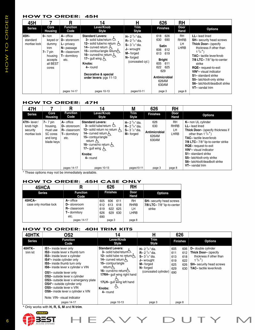
ER HOW TO ORDER: 45H
45HSeries
7Core
Housing
RFunction
Code
14Lever/Knob
Style
HTrimStyle
626Finishes
45H– standard mortise lock
0– non keyed ordummy trim
7– 7 pin housingacceptsall BESTcores
RHDoorHand Options
A– officeD– storeroomL– privacy N– passage R– classroomT– dormitory
etc.
H– 2 3/4" dia.R– 2 3/4" dia.S– 3 1/2" dia.J– wrought M– forgedN– forged
(concealed cyl.)
618 626630 690
Satin606 612613 619
Bright605 611622 625
629
Antimicrobial626AM630AM
RHRHRB
LHLHRB
LL– lead linedSH– security head screwsThick Door– (specify
thickness if other than1 3/4" )
TAC– tactile lever/knob7/8 LTC– 7/8" lip-to-center
strikeRQE– request-to-exitVIN*– visual indicatorS1– standard strikeS5– latchbolt-only strikeS6– latchbolt/deadbolt strikeVT– vandal trim
HOW TO ORDER: 47H
47HSeries
7Core
Housing
RFunction
Code
14Lever/Knob
Style
MTrimStyle
626Finishes
47H– lever /knob high security mortise lock
7– 7 pin housing,must use 5C cores and long blade keys
RHDoorHand Options
A– officeD– storeroomR– classroomT– dormitory
etc.
H– 2 3/4" dia.R– 2 3/4" dia.S– 3 1/2" dia.M– forged
RHRHRB
LHLHRB
K– non UL cylinderLL– lead linedThick Door– (specify thickness if
other than 1 3/4" )TAC– tactile lever/knob7/8 LTC– 7/8" lip-to-center strikeRQE– request-to-exitVIN*– visual indicatorS1– standard strikeS5– latchbolt-only strikeS6– latchbolt/deadbolt strikeVT– vandal trim
pages 14-17
HOW TO ORDER: 40H TRIM KITS
40HTKSeries
OS2Function
Code
14Lever/Knob
Style
626Finishes
40HTK– trim kit
Options
IS1– inside lever onlyIS2– inside lever x thumb turnIS3– inside lever x cylinderIS4*– inside cylinder onlyIS5– inside thumb turn onlyIS6– inside lever x cylinder x VIN
OS1– outside lever onlyOS2– outside lever x cylinderOS3– outside lever x emergency plateOS4*– outside cylinder onlyOS5– outside lever x VINOS6– inside lever x cylinder x VIN
Note: VIN– visual indicator
D– double cylinderThick Door– (specify
thickness if other than1 3/4" )
SH– security head screwsTAC– tactile lever/knob
page 3 page 8page 10-13pages 14-17
HOW TO ORDER: 45H CASE ONLY
45HCASeries
RFunction
Code
626Finishes
45HCA– case only mortise lock
Options
A– officeD– storeroomR– classroomT– dormitory
etc.
SH– security head screws7/8 LTC– 7/8" lip-to-center
strike
page 3 page 8pages 14-17
605 606 611612 613 618619 622 625626 629 630690
HTrimStyle
H– 2 3/4" dia.R– 2 3/4" dia.S– 3 1/2" dia.J– wrought M– forgedN– forged
(concealed cylinder)
605 606611 612613 618619 622625 626629 630690
RHDoorHand
RHRHRB
LHLHRB
* These options may not be immediately available.
* Only works with H, R, S, M and N trim.
pages10-11 page 8page 3pages 10-13pages 14-17
Standard Levers:3– solid tube/return
12– solid tube/no return14– curved return15– contour/angle return16– curved/no return17– gull wing
Knobs:4– round
Decorative & special order levers: pgs 11-13
pages10-11 page 8page 3pages 10-13
Standard Levers:3– solid tube/return
12– solid tube no return14– curved return15– contour/angle
return16– curve/no return17RH– gull wing right hand
17LH– gull wing left hand
Knobs:4– round
626630
Antimicrobial626AM630AM

Levers:3– solid tube/return
12– solid tube/no return14– curved return15– contour/angle return16– curve/no return17RH– gull wing-right hand17LH– gull wing-left hand
Knobs:4– round
Decorative & special order levers: pages 11-13
77O R T I S E L O C K S
HO
W T
O O
RD
ERHOW TO ORDER: 40H STRIKE PACKAGES
40HSTSeries
1Kit Number
626Finishes
40HST– strike package
Options
S1– standard strikeS5– latchbolt-only strikeS6– latchbolt/deadbolt strike4– strike box only
Thick Door– (specify thickness if other than 1 3/4" )
7/8LTC– 7/8" lip-to-center strikeSH– security head screws
605 606 611612 613 618 619 622 625626 629 630690
HOW TO ORDER: 40H LEVER SETS
40HLSSeries
14Lever/Knob
Style40HLS–
lever set
Options
Thick Door– (specify thicknessif other than 1 3/4" )
SH– security head screwsVT– vandal trim
page 3page 3
HOW TO ORDER: 40H FACEPLATE KITS
40HFPSeries
40HFP– faceplate kit
Options
SH– security head screws
page 3page 4-5
3Kit
Number
626Finishes
0– AB1– BW, TD, H, HJ2– A3– AT, D, C, INL,
NX, R, W4– N, LT5– AD, RD, YD, WD
605 606611 612 613 618 619 622625 626629 630 690
HOW TO ORDER: 40H REPLACEMENT SPINDLES
40HRSSeries
40HRS– replacement spindle kits
Options
page 3
2Function
Code2– 40H split spindle (standard)4– 40H hook spindle *
HOW TO ORDER: 40H SCREW KITS
40HSKSeries
40HSK– screw kits
Options
page 3page 4-5
1Kit
Number
626Finishes
1– H, R. S, J trim screw kit 2– M, N trim screw kit3– special purpose fasteners screw kit 4– surface mounted trim screw kit5– VIN trim screw kit
606612613622626
626Finishes
605 606611 612613 618619 622625 626629 630690
Thick Door– (specify thickness if other than 1 3/4" )
Thick Door– (specify thicknessif other than 1 3/4" )
SH– security head
*Hook spindle is available for 1 3/4" thick door only.
page 3page 4-5
6– blank7– BA, S, TA8– B, G, IND, L, LB, T9– CHB, RHB
10– blank (without logo)
HOW TO ORDER: 40H VANDAL TRIM RETROFIT KIT
40HVTKSeries
40HVTK– vandal trim kit
Options
page 3
2LeverStyle
14*– curved return15– contour/angle return
Thick Door– (specify thickness ifother than 1 3/4" )
*Complies with California Building Code Title 10 and Title 24, part 12
626LeverStyle
605, 606, 611, 612, 613618 619, 622, 625, 626629, 630, 690
88 H E AV Y D U T Y M
SPECIAL FEATURES
SP
EC
IA
L FEA
TU
RES
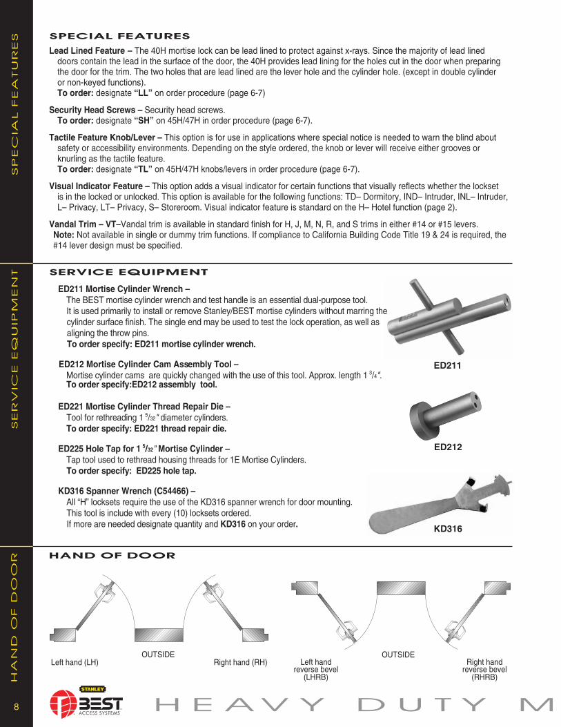
Lead Lined Feature – The 40H mortise lock can be lead lined to protect against x-rays. Since the majority of lead lined doors contain the lead in the surface of the door, the 40H provides lead lining for the holes cut in the door when preparing the door for the trim. The two holes that are lead lined are the lever hole and the cylinder hole. (except in double cylinder or non-keyed functions). To order: des ig nate “LL” on order pro ce dure (page 6-7)
Security Head Screws – Security head screws. To order: des ig nate “SH” on 45H/47H in order procedure (page 6-7).
Tactile Feature Knob/Lever – This option is for use in applications where special notice is needed to warn the blind about safety or accessibility environments. Depending on the style ordered, the knob or lever will receive either grooves or knurling as the tactile feature. To order: des ig nate “TL” on 45H/47H knobs/levers in order pro ce dure (page 6-7).
Visual Indicator Feature – This option adds a visual indicator for certain functions that visually reflects whether the lockset is in the locked or unlocked. This option is available for the following functions: TD– Dormitory, IND– Intruder, INL– Intruder, L– Privacy, LT– Privacy, S– Storeroom. Visual indicator feature is standard on the H– Hotel function (page 2).
Vandal Trim – VT–Vandal trim is available in standard finish for H, J, M, N, R, and S trims in either #14 or #15 levers. Note: Not available in single or dummy trim functions. If compliance to California Building Code Title 19 & 24 is required, the #14 lever design must be specified.
OUTSIDELeft hand Right hand
reverse bevel re verse bevel(LHRB) (RHRB)
hAND OF DOOR
HA
nD
O
F D
OO
R
OUTSIDELeft hand (LH) Right hand (RH)
SERvICE EQUIPMENT
SER
VIC
E EQ
UIP
MEn
T
ED211 Mortise Cylinder Wrench – The BEST mortise cylinder wrench and test handle is an essential dual-purpose tool.It is used primarily to install or remove Stanley/BEST mortise cylinders without marring the cylinder surface finish. The single end may be used to test the lock operation, as well as aligning the throw pins.To order specify: ED211 mortise cylinder wrench.
ED212 Mortise Cylinder Cam Assembly Tool –Mortise cylinder cams are quickly changed with the use of this tool. Ap prox . length 1 3/4". To order specify:ED212 assembly tool.
ED221 Mortise Cylinder Thread Repair Die –Tool for rethreading 1 5/32" diameter cylinders.To order specify: ED221 thread repair die.
ED225 Hole Tap for 1 5/32" Mortise Cylinder –Tap tool used to rethread housing threads for 1E Mortise Cylinders. To order specify: ED225 hole tap.
KD316 Spanner Wrench (C54466) –All “H” locksets require the use of the KD316 spanner wrench for door mounting. This tool is include with every (10) locksets ordered. If more are needed designate quantity and KD316 on your order.
ED212
ED211
KD316

99 O R T I S E L O C K S
A. Locksets and Latch sets: [Best Access Systems.] - [ .] [ .] 1. Base Specification: Best Access Systems components as listed in Hardware Schedule per Article 3.05. 2. Locksets and latchsets of other acceptable manufacturers must conform to the requirements of Subparagraphs 3 and 4. 3. Mortise Type: a. Locksets shall be tested and approved by BHMA for ANSI A156.13, Series 1000, Operational Grade 1, Extra-Heavy Duty, Security Grade 2 and be UL10C b. Locksets shall be mortise type with solid 3/4 inch throw one-piece radiused latchbolt made of self-lubricating stainless steel. Deadbolt functions shall be one inch projection stainless steel construction. Both deadbolt and latchbolt to extend into lock case with reinforcing a minimum of 3/8 inch when fully extended. c. Knobs to be [ ] design. Levers to be [ ] design. d. Furnish locksets and latchsets with sufficient strike lip to protect door trim. e. Provide locksets with 7 pin [BEST] interchangeable core cylinders. [All mortise cylinders shall have a concealed internal set screw for securing the cylinder to the lockset. The internal set screw will be accessible only by removing the core from the cylinder body with a control key] f. All mortise locksets and latchsets must conform to ANSI A156.13, Series 1000, Operational Grade 1 [Security Grade 2 for locksets in security areas] and be listed by UL. [High Security Option: All mortise locksets must conform to ANSI A156.13, Series 1000, Operational Grade 1, Security Grade 1 and listed by UL, and must include inter changeable core cylinders which conform to High Security Cylinder requirements of UL 437.] g. Locksets must fit ANSI A115.1 door preparation. h. Locksets and latchsets to have self-aligning through-bolted trim. i. Locksets and latchsets must have the ability to change handing without opening case. j. Auxiliary latch to be made of one-piece self-lubricating stainless steel. k. Locksets must be available with tactile or knurled knobs or levers for identification of hazardous areas. l. Lever handles must be of forged or cast brass, bronze or stainless steel construction and conform to ANSI A117.1. Levers which contain a hollow cavity are not acceptable. Subparagraphs m through r describe quality features of Best mortise locksets which may or may not be available from other lock manufacturers. Edit accordingly.
m.[Spindle to be such that if forced it will twist first, then break, thus preventing forced entry.] n. [Knobs and levers to be operated with a roller bearing spindle hub mechanism.] o. [Permanent core face must be the same finish as the lockset finish.] p. [Cylinder retaining screw, auxiliary latch, and strike must be non-handed.] q. [Locking toggle on face of door must clearly indicate whether mortise lock is in the “locked” or “unlocked” state.] r. [Cover and armored front must interlock at the latch, preventing the cover from spreading or bowing while under duress.]
Subparagraphs s through x describe quality features of Best mortise locksets which may or may not be available from other lock manufacturers. Subparagraphs s, t, and u should remain as a group, and subparagraphs v, w, and x should remain as a group. Choose either s-u or v-x, but not both groups.
s. [Mortise lock to offer a complete lock (including trim) with the ability to be configured in the field to any of the following ANSI functions: F01, F04, F05, F07, F31.] t. [Mortise lock to offer a complete lock (including trim) with the ability to be configured in the field to any of the following ANSI functions: F19, F13] u. [Mortise lock to offer a complete lock (including trim) with the ability to be configured in the field to any of the following ANSI functions: F12, F20] v. [Mortise lock to offer a multi-function case with the ability to be configured in the field to any of the following ANSI functions: F01, F04, F05, F07, F09, F30, F31, F32.] w.[Mortise lock to offer a multi-function case with the ability to be configured in the field to any of the following ANSI functions: F13, F19, F33.] x. [Mortise lock to offer a multi-function case with the ability to be configured in the field to any of the following ANSI functions: F12, F15, F20]
MORTISE SAMPLE SPECIFICATIONS
MO
RTISE SA
MP
LE SP
EC
IFIC
ATIO
nS
10 H E AV Y D U T Y M
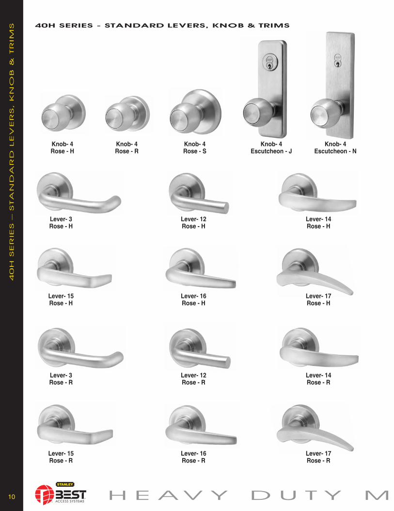
40h SERIES - STANDARD LEvERS, KNOb & TRIMS
40H
SER
IES – STA
nD
AR
D LEV
ER
S, K
nO
B &
TR
IM
S
Knob- 4 Knob- 4 Knob- 4 Knob- 4 Knob- 4Rose - H Rose - R Rose - S Escutcheon - J Escutcheon - N
Lever- 3 Lever- 12 Lever- 14Rose - H Rose - H Rose - H
Lever- 3 Lever- 12 Lever- 14Rose - R Rose - R Rose - R
Lever- 15 Lever- 16 Lever- 17Rose - H Rose - H Rose - H
Lever- 15 Lever- 16 Lever- 17Rose - R Rose - R Rose - R
11 O R T I S E L O C K S
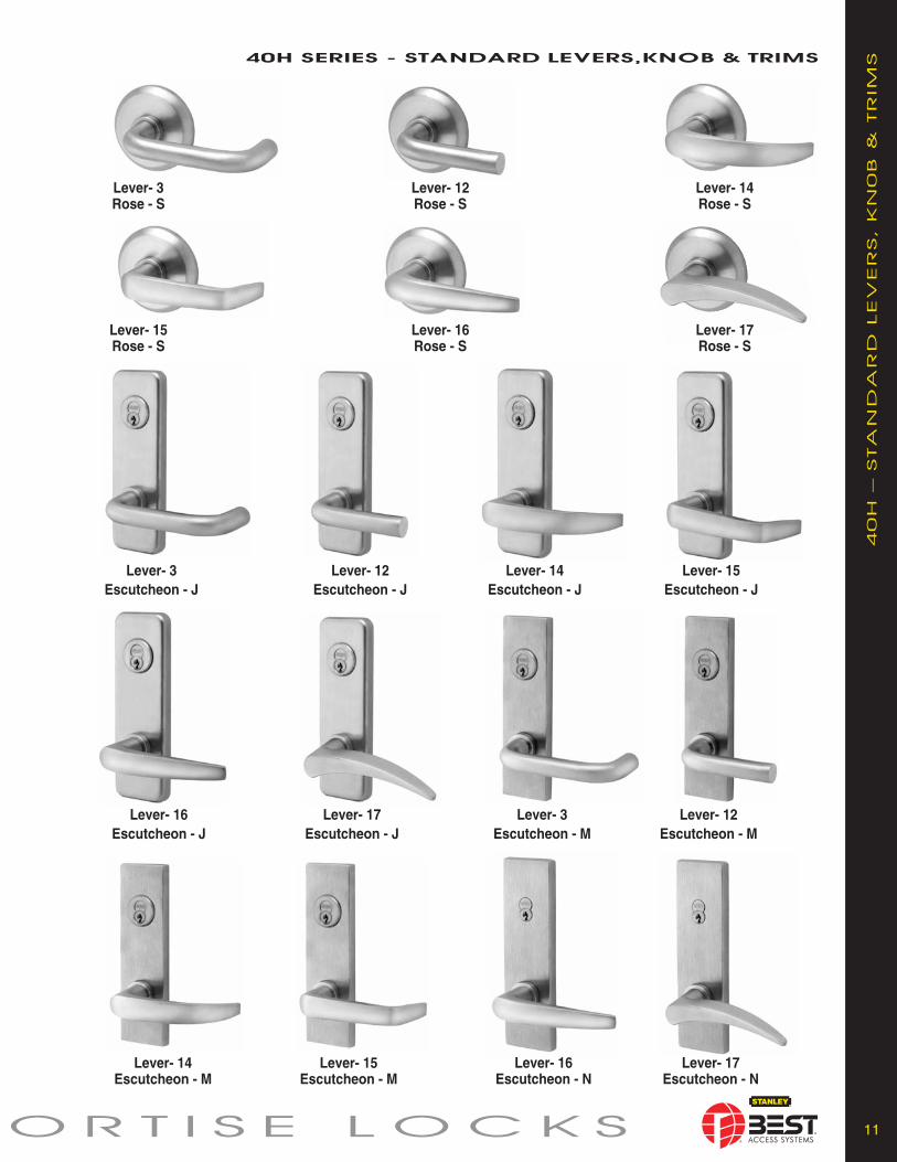
40h SERIES - STANDARD LEvERS,KNOb & TRIMS
40H
– STA
nD
AR
D LEV
ER
S, K
n0B
&
TR
IM
S
Lever- 3 Lever- 12 Lever- 14Rose - S Rose - S Rose - S
Lever- 15 Lever- 16 Lever- 17Rose - S Rose - S Rose - S
Lever- 3 Lever- 12 Lever- 14 Lever- 15Escutcheon - J Escutcheon - J Escutcheon - J Escutcheon - J
Lever- 16 Lever- 17 Lever- 3 Lever- 12Escutcheon - J Escutcheon - J Escutcheon - M Escutcheon - M
Lever- 16 Lever- 17Escutcheon - N Escutcheon - N
Lever- 14 Lever- 15Escutcheon - M Escutcheon - M

12 H E AV Y D U T Y M
40h SERIES - DECORATIvE LEvERS
40H
SER
IES – D
EC
OR
ATIV
E LEV
ER
S
# 50 # 51 # 52
# 53 # 54 # 55
# 60 # 61 # 62
# 63 # 64 # 65
# 67 # 68# 66
# 69 # 70 # 71
# 72 # 73 # 74
13 O R T I S E L O C K S
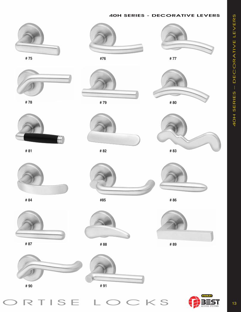
# 75 #76 # 77
# 78 # 79 # 80
# 81 # 82 # 83
# 84 #85 # 86
# 87 # 88 # 89
40h SERIES - DECORATIvE LEvERS
40H
SER
IES – D
EC
OR
ATIV
E LEV
ER
S
# 91# 90

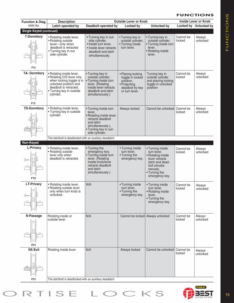
HJ-Hotel
F15
Cannot be locked
Alwaysunlocked
• Turning inside turn lever,• Turning emergency key in O/S cylinder. (Rotating inside lever retracts deadbolt and latch simultaneously.)
Always locked Cannot be unlocked• Rotating inside lever, • Turning key in outside cylinder.
The latchbolt is deadlocked with an auxiliary deadlatch. Throwing deadbolt blocks out all keys except “ER” key.
Alwaysunlocked
Cannot be locked
Always locked Cannot be unlocked• Rotating inside lever, •Turning key in outside cylinder.
1414 H E AV Y D U T Y M
Function & Diag.ANSI No.
AB-Office
Single KeyedUnlocked by
F04
F07
F05
F06
F20
Description Inside Lever or KnobOutside Lever or KnobLatch operated by Unlocked byDeadbolt operated by Locked by
FUNCTIONS
Locked by
AT-Office
R-Classroom
The latchbolt is deadlocked with an auxiliary deadlatchRHB-Classroom
Holdback
F04
A-Office
FU
nC
TIO
nS
Alwaysunlocked
Cannot be locked
N/A Placing locking toggle in unlockedposition
• Rotating inside lever, • Rotating outside lever– only when locking toggle is in unlocked position, • Turning key in outside cylinder.
Placing lockingtoggle in lockedposition
Alwaysunlocked
Cannot be locked
N/A • Turning inside turn lever,• Turning key in outside cylinder.
• Rotating inside lever, • Rotating outside lever only when unlocked by key or turn lever,• Turning key in outside cylinder.
• Turning inside turn lever, • Turn key in outside cylinder.
Alwaysunlocked
Cannot be locked
• Turning key in outside cylinder,• Inside turn lever,• Inside lever retracts deadbolt and latchsimultaneously.
Turning key in outside cylinder and placing lockingtoggle in unlockedposition
• Rotating inside lever,• Rotating outside lever–only when locking toggle is in unlocked position,• Turning key in outside cylinder.
• Placing locking toggle in locked position,• Projecting dead-bolt by key or turn lever.
Cannot be locked
Alwaysunlocked
N/A Always locked Cannot be unlocked• Rotating inside lever, • Turning key in outside cylinder.
Cannot be locked
Alwaysunlocked
N/A Turning key in outside cylinder
Turning key in outside cylinder
• Rotating inside lever,• Turning key in outside cylinder,• O/S lever except when locked by outside key,• Latchbolt held retracted by turning O/S key while holding up I/S lever.
Alwaysunlocked
Cannot be locked
N/A Turning key inoutside cylinder
Turning key in outside cylinder
• Rotating inside lever, • Rotating outside lever only when unlocked by key,•Turning key in outside cylinder.
The latchbolt is deadlocked with an auxiliary deadlatch
The latchbolt is deadlocked with an auxiliary deadlatch
The latchbolt is deadlocked with an auxiliary deadlatch
D-Storeroom
The latchbolt is deadlocked with an auxiliary deadlatch
The latchbolt is deadlocked with an auxiliary deadlatchH-Hotel • Turning inside turn
knob• Turning key in O/S cylinder.(Rotating inside leverretracts deadbolt andlatch simultaneously).
F15 The latchbolt is deadlocked with an auxiliary deadlatch. Throwing deadbolt blocks out all keys except “ER” key.
Cannot be locked
Alwaysunlocked
• Turning inside turn lever,• Rotating inside lever retracts deadbolt and latch simultaneously.),• Turning key in out-side cylinder.
Cannot be unlocked• Rotating inside lever, • Turning key in outside cylinder.
TD-Dormitory
TA- Dormitory
F12
Always locked
Cannot be locked
Alwaysunlocked
• Turning key in outside cylinder, • Turning inside turn lever. (Rotating inside lever retracts deadbolt and latch simultaneously.)
• Placing locking toggle in locked position, • Projecting deadbolt by keyor turn lever.
Turning key in outside cylinderand placing lockingtoggle in unlockedposition
• Rotating inside lever, • Rotating O/S lever only when locking toggle is in unlocked position and deadbolt is retracted,• Turning key in outside cylinder.
The latchbolt is deadlocked with an auxiliary deadlatch
1515 O R T I S E L O C K S
Function & Diag.ANSI No.
Single Keyed (continued)Unlocked by
FU
nC
TIO
nS
Description Inside Lever or KnobOutside Lever or KnobLatch operated by Unlocked byDeadbolt operated by Locked by
FUNCTIONS
Locked by
Non-Keyed
F19
L-Privacy
N-Passage
F01
LT-Privacy
NX-Exit
F31
• Turning the emergency key, • Turning inside turn lever. (Rotating inside knob/lever retracts deadbolt and latch simultaneously.)
• Rotating inside lever, • Rotating outside lever only when deadbolt is retracted.
Alwaysunlocked
Cannot belocked
• Turning inside turn lever,• Rotating inside lever retracts latch and dead-bolt si mul ta- neous ly,• Turning the emergency key.
• Turning inside turn lever, • Turning the emergency key.
Cannot belocked
Alwaysunlocked
Rotating inside or outside lever
Always unlockedN/A Cannot be locked
Cannot belocked
Alwaysunlocked
Rotating inside lever Cannot be unlockedAlways lockedN/A
N/A• Rotating inside lever,• Rotating outside lever only when turn knob isunlocked.
Alwaysunlocked
Cannot belocked
• Turning inside turn lever,• Rotating inside lever, • Turning the emergency key.
• Turning inside turn lever, • Turning the emergency key.
The latchbolt is deadlocked with an auxiliary deadlatch
F13
Cannot be locked
Alwaysunlocked
• Turning key in out-side cylinder, • Inside turn lever, • Inside lever retracts deadbolt and latchsimultaneously.
• Turning key in outside cylinder, • Turning inside turn lever.
• Turning key in outside cylinder, • Turning inside turnlever, • Rotating inside lever.
• Rotating inside lever, • Rotating outside lever—only when deadbolt is retracted• Turning key in outside cylinder.
T-Dormitory

The latchbolt is deadlocked with an auxiliary deadlatch. When required, inside cylinder may be combinated to operateby master key only.
1616 H E AV Y D U T Y M
FU
nC
TIO
nS FUNCTIONS
Double Keyed*
F09
G-Communicating
F14
F33
F32
F35
*S-Storeroom
Outside Lever or Knob Inside Lever or KnobLocked by
Function & Diag.ANSI No. Latch operated by Deadbolt operated by
DescriptionLocked by Unlocked by Unlocked by
IND-Intruder
INL-Intruder
CHB-Holdback
Turning key ininside or outsidecylinder
Turning key ininside or outsidecylinder
Rotating inside or outsidelever— only when deadboltis retracted
Turning key in insideor outside cylinder
Turning keyin inside oroutsidecylinder
Turning keyin inside oroutsidecylinder
• Turning key in outside or inside cylinder, • Rotating inside lever (Retracts the deadbolt and latchsimultaneously).
Extending the deadbolt by turning key in inside or outsidecylinder
• Turning key in inside or outside cylinder,• Rotating outside lever when deadbolt is retracted,• Rotating inside lever.
• Retracting the deadbolt by turning key in inside or outside cylinder,• Rotating inside lever (Retracts the deadbolt and latch simultaneously).
Alwaysunlocked
Cannot belocked
N/A• Rotating inside lever, • Rotating outside lever only when unlocked by inside or outside key, • Turning key in inside or outside cylinder.
Alwaysunlocked
Turning key in insideor outside cylinder
Cannot belocked
Turning key ininside or outsidecylinder
Turning key ininside or outsidecylinder
Placing lockingtoggle in lockedposition
• Rotating inside lever, • Rotating outside lever only when locking toggle is in unlocked positionand deadbolt is retracted, • Turning key in inside or outside cylinder.
Turning key in outside cylinder or inside cylinder and placing locking toggle in unlocked position
Retractingthe deadbolt
Extendingthe deadbolt
*C-PublicEntrance
N/A• Rotating inside lever,• Rotating outside leveronly when unlocked bykey in inside cylinder, • Turning key in outside cylinder only.
Alwaysunlocked
Turning key in inside cylinder
Cannot belocked
Turning key ininside cylinder
N/A Alwaysunlocked
Turning key in inside cylinder
Cannot belocked
Turning key ininside cylinder
• Turning outside key,• Rotating outside leveronly when unlocked bykey in inside cylinder,• Inside lever,• Latchbolt held retracted by turning inside key while holding up on inside lever.
The latchbolt is deadlocked with an auxiliary deadlatch. When required, inside cylinder may be combinated to operateby master key only.
The latchbolt is deadlocked with an auxiliary deadlatch.
*ATTENTION: Locksets that secure both sides of the door are controlled by building codes and the Life Safety Code®. In an emergency exit situation, failure toquickly unlock the inside lever could be hazardous or even fatal.
F34
INA-Intruder • Turning key in outside or inside cylinder, • Rotating inside lever (Retracts the deadbolt and latchsimultaneously).
Extending the deadbolt by turning key in inside or outsidecylinder
• Turning key in inside or outside cylinder,• Rotating outside lever when deadbolt is retracted,• Rotating inside lever.
• Retracting the deadbolt by turning key in inside or outside cylinder,• Rotating inside lever (Retracts the deadbolt and latch simultaneously).
Alwaysunlocked
Cannot belocked
The latchbolt is deadlocked with an auxiliary deadlatch. When required, inside cylinder may be combinated to operateby master key only.

1717 O R T I S E L O C K S
AD-Deadlock
F17
F29
F18
F16
FU
nC
TIO
nS
RD-ClassroomDeadlock
Inside Lever or KnobLocked by
Function & Diag.ANSI No. Latch operated by Deadbolt operated by
DescriptionLocked by Unlocked by Unlocked by
Outside Lever or KnobFUNCTIONS
YD-Deadlock
WD-Deadlock
N/A • Turning key in outside cylinder • Turning inside turn lever.
N/A N/AN/A N/A
N/A• Turning key inoutside cylinder• Turning inside turn lever.*
N/A N/AN/A
*Function RD–the inside turn knob retracts deadbolt but will not project it. (Specify hand of door.) N/AN/A Turning key in outside
cylinder onlyN/A N/AN/A
Turning key in outsideor inside cylinder
N/A N/AN/A N/AN/A
The latchbolt is deadlocked with an auxiliary deadlatch*ZD-Storeroom
Cannot be locked
Alwaysunlocked
N/A N/A N/A• Rotating inside lever, • Turning key in outsidecylinder.
N/A N/AN/A Alwayslocked
Cannot beunlocked
Turning key in outside cylinder
Alwaysunlocked
Cannot be locked
N/A N/A N/A• Rotating inside lever, •Turning key in outside cylinder.• Latchbolt held retracted by turning O/S key while holding up I/S lever
The latchbolt is deadlocked with an auxiliary deadlatch
N/A
*ATTENTION: Locksets that secure both sides of the door are controlled by building codes and the Life Safety Code®. In an emergency exit situation, failure toquickly unlock the inside lever could be hazardous or even fatal.
XRHB-ClassroomHoldback
XR-Classroom
Double Keyed* (continued)
Deadlocks
Special
F30
*W-Storeroom
The latchbolt is deadlocked with an auxiliary deadlatch. When required, inside cylinder may be combinated to operate by master key only.
Turning key in inside oroutside cylinder
N/A Always locked
Alwayslocked
Cannot beunlocked
Cannot be unlocked
1818 H E AV Y D U T Y M
*ATTENTION: Locksets that secure both sides of the door are controlled by building codes and the Life Safety Code®. In an emer gen cy exit situation, failure to quickly retract the deadbolt could be hazardous or even fatal.
NOTES: Specify the hand of door when ordering. The R function deadlock can only be used on 1 3/4" thick doors.
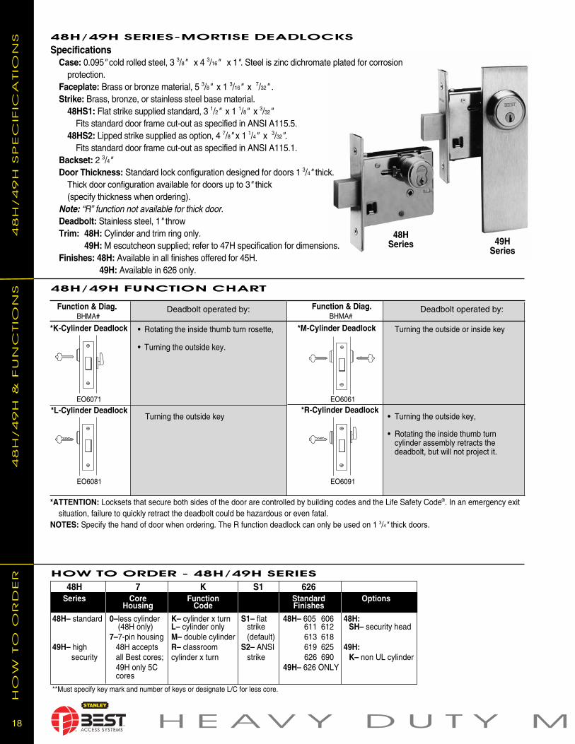
*L-Cylinder Deadlock
48H/49H FUNCTION CHART
EO6071 EO6061
Function & Diag.BHMA#
*K-Cylinder Deadlock • Rotating the inside thumb turn rosette,
• Turning the outside key.
Turning the outside key
Deadbolt operated by: Function & Diag.BHMA#
*M-Cylinder Deadlock Turning the outside or inside key
• Turning the outside key,
• Rotating the inside thumb turn cylinder assembly retracts the deadbolt, but will not project it.
Deadbolt operated by:
*R-Cylinder Deadlock
EO6081 EO6091
HOW TO ORDER - 48H/49H SERIES
48H/49H SERIES-MORTISE DEAD LOCKS
48H
/49H
SP
EC
IFIC
ATIO
NS
48H
/4
9H
& F
UN
CTIO
NS
HO
W T
O O
RD
ER
48H 7 K S1 626Series Core Function Standard Options
Housing Code Finishes
48H– standard 0–less cylinder K– cylinder x turn S1– flat 48H– 605 606 48H: (48H only) L– cylinder only strike 611 612 SH– security head 7–7-pin housing M– double cylinder (default) 613 618 49H– high 48H accepts R– classroom S2– ANSI 619 625 49H: security all Best cores; cylinder x turn strike 626 690 K– non UL cylinder
49H only 5C 49H– 626 ONLY cores
**Must specify key mark and number of keys or designate L/C for less core.
Specifications Case: 0.095" cold rolled steel, 3 3/8" x 4 3/16" x 1". Steel is zinc dichromate plated for corrosion protection. Faceplate: Brass or bronze material, 5 3/8" x 1 3/16" x 7/32" . Strike: Brass, bronze, or stainless steel base material. 48HS1: Flat strike supplied standard, 3 1/2" x 1 1/8" x 3/32" Fits standard door frame cut-out as specified in ANSI A115.5. 48HS2: Lipped strike supplied as option, 4 7/8" x 1 1/4" x 3/32". Fits standard door frame cut-out as specified in ANSI A115.1. Backset: 2 3/4" Door Thickness: Standard lock configuration designed for doors 1 3/4" thick. Thick door configuration available for doors up to 3" thick (specify thickness when ordering). Note: “R” function not available for thick door. Deadbolt: Stainless steel, 1" throw Trim: 48H: Cylinder and trim ring only. 49H: M escutcheon supplied; refer to 47H specification for dimensions. Finishes: 48H: Available in all finishes offered for 45H. 49H: Available in 626 only.
48HSeries 49H
Series
1919 O R T I S E L O C K S
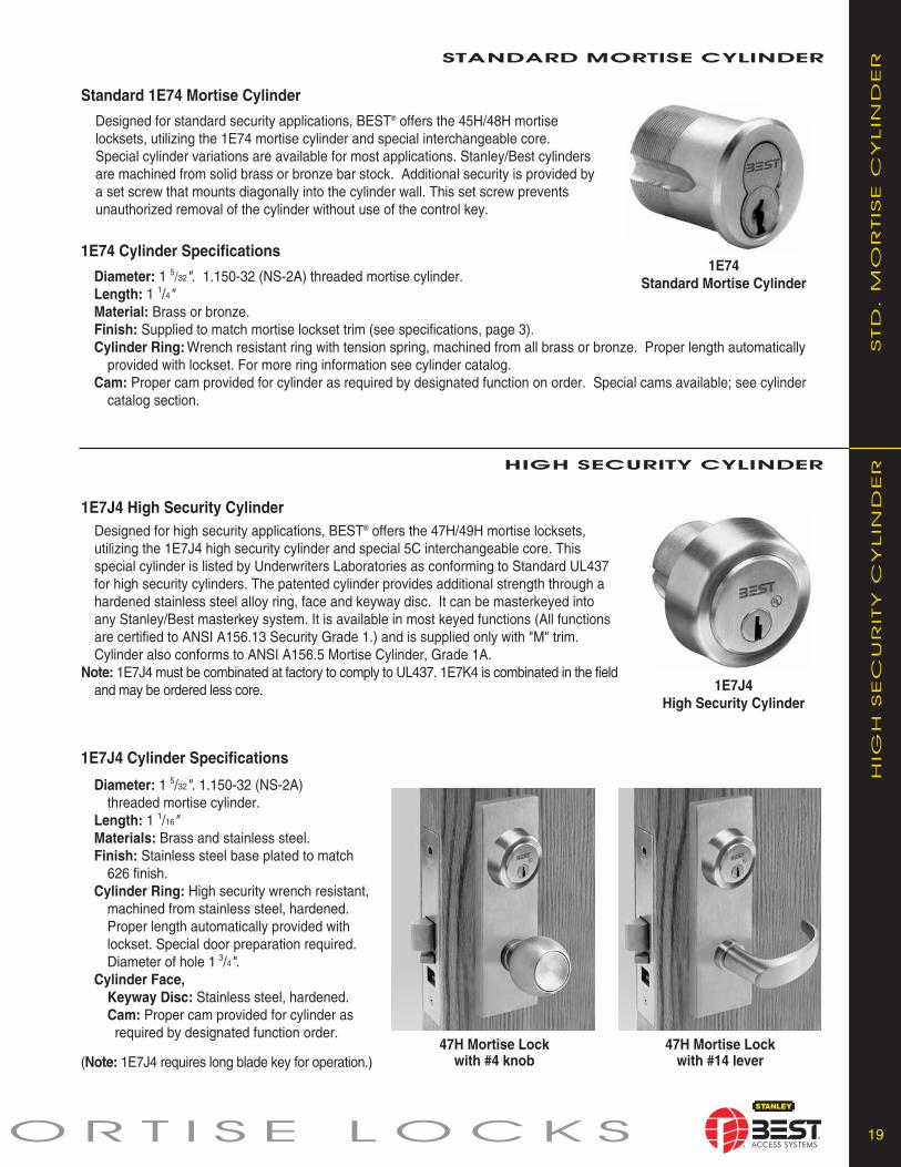
1E74 Cylinder Specifications
Diameter: 1 5/32". 1.150-32 (NS-2A) threaded mortise cylinder. Length: 1 1/4" Material: Brass or bronze. Finish: Supplied to match mortise lockset trim (see spec i fi ca tions, page 3). Cylinder Ring:Wrench resistant ring with tension spring, machined from all brass or bronze. Proper length automatically provided with lockset. For more ring information see cylinder catalog. Cam: Proper cam provided for cylinder as required by designated function on order. Spe cial cams available; see cylinder catalog section.
hIgh SECURITy CyLINDER
1E7J4 High Security CylinderDesigned for high security applications, BEST® offers the 47H/49H mortise locksets, utilizing the 1E7J4 high security cylinder and special 5C in ter change able core. This special cylinder is listed by Underwriters Lab o ra to ries as conforming to Standard UL437 for high se cu ri ty cyl in ders. The patented cylinder provides ad di tion al strength through a hardened stainless steel alloy ring, face and keyway disc. It can be mas ter keyed into any Stanley/Best masterkey system. It is available in most keyed functions (All functions are certified to ANSI A156.13 Security Grade 1.) and is supplied only with "M" trim. Cylinder also con forms to ANSI A156.5 Mortise Cyl in der, Grade 1A.
Note: 1E7J4 must be combinated at factory to comply to UL437. 1E7K4 is combinated in the field and may be or dered less core.
Standard 1E74 Mortise Cylinder
Designed for standard security applications, BEST® offers the 45H/48H mortise locksets, utilizing the 1E74 mortise cyl in der and special interchangeable core. Special cylinder vari a tions are avail able for most ap pli ca tions. Stanley/Best cyl in ders are machined from solid brass or bronze bar stock. Ad di tion al se cu ri ty is pro vid ed by a set screw that mounts di ag o nal ly into the cylinder wall. This set screw prevents un au thorized re mov al of the cylinder with out use of the control key.
STANDARD MORTISE CyL IN DER
STD
. M
OR
TISE C
YLIn
DER
HIG
H SEC
UR
ITY
C
YLIn
DER
47H Mortise Lockwith #14 lever
47H Mortise Lock with #4 knob
1E7J4 High Security Cylinder
1E74 Standard Mortise Cylinder
1E7J4 Cylinder Specifications
Diameter: 1 5/32". 1.150-32 (NS-2A) threaded mortise cylinder. Length: 1 1/16" Materials: Brass and stainless steel. Finish: Stainless steel base plated to match 626 finish. Cylinder Ring: High security wrench resistant, ma chined from stainless steel, hardened. Proper length automatically provided with lockset. Special door preparation re quired. Diameter of hole 1 3/4". Cylinder Face, Keyway Disc: Stainless steel, hard ened. Cam: Proper cam provided for cylinder as required by designated function order.
(Note: 1E7J4 requires long blade key for operation.)

ecuritysolutions.com
Stanley Security Solutions, Inc.6161 E. 75th Street Indianapolis, Indiana 46250
© 2011 Stanley Security Solutions, Inc. • www.stanleysecuritysolutions.com
srorrE .elbissop ylbanosaer si sa ssen etelp moc dna erac hcum sa htiw detneserp dna delip moc neeb sah golatac siht ni deniatnoc noitamrofni tcudorPor mistakes may be present, and in many cases, reliance has been placed on information supplied by other manufacturers which may be in error or
ro edam eb nac eet na raug on ,eroferehT .noitagilbo tuohtiw dna ecit on tuo htiw re rut caf u nam eht yb snoit ac if i dom ro segnahc ot tcejbus eb yam hcihw.golatac siht ni deniat noc noit am rof ni tcudorp ot sdrager htiw deilpmi ro demussa eb dluohs
10M R311BAS018
MO
RT
IS
E L
OC
KS
ET
S