Heavy Duty Hydraulic Roundline Cylinders
64
aerospace climate control electromechanical filtration fluid & gas handling hydraulics pneumatics process control sealing & shielding Heavy Duty Hydraulic Roundline Cylinders Series RDH
Transcript of Heavy Duty Hydraulic Roundline Cylinders
aerospaceclimate control electromechanicalfiltrationfluid & gas handlinghydraulicspneumaticsprocess controlsealing & shielding
Heavy Duty Hydraulic Roundline CylindersSeries RDH
Heavy Duty Hydraulic Roundline CylindersSeries RDH
Miller Fluid PowerIndustrial Cylinder DivisionDes Plaines, Illinois USAwww.millerfluidpower.com
Catalog HY08-M1320-1/NA
In line with our policy of continuing product improvement, specifications and information contained in this catalog are subject to change.
Copyright ©2011 by Parker Hannifin Corporation. All rights reserved.
PRINTED IN THE U.S.A.
WARNINGFAILURE OR IMPROPER SELECTION OR IMPROPER USE OF THE PRODUCTS AND/OR SYSTEMS DESCRIBED HEREIN OR RELATED ITEMS CAN CAUSE DEATH, PERSONAL INJURY AND PROPERTY DAMAGE.This document and other information from the Parker Hannifin Corporation, its subsidiaries and authorized distributors provide product and/or system options for further investigation by users having expertise. It is important that you analyze all aspects of your application, including consequences of any failure and review the information concerning the product or system in the current product catalog. Due to the variety of operating conditions and applications for these products or systems, the user, through its own analysis and testing, is solely responsible for making the final selection of the products and systems and assuring that all performance, safety and warning requirements of the application are met.The products described herein, including without limitation, product features, specifications, designs, availability and pricing, are subject to change by Parker Hannifin Corporation and its subsidiaries at any time without notice.
Offer of SaleThe items described in this document are hereby offered for sale by Parker Hannifin Corporation, its subsidiaries or its authorized distributors. This offer and its acceptance are governed by provisions stated on a separate page of the document entitled ‘Offer of Sale’.

Heavy Duty Hydraulic Roundline CylindersSeries RDH
www.millerfluidpower.com
Catalog HY08-M1320-1/NA
Miller Fluid PowerIndustrial Cylinder DivisionDes Plaines, Illinois USA
I
Miller Fluid Power, manufacturer of the world's most diverse selection of hydraulic and pneumatic cylinders, is the single source of fluid power linear actuators for today's industrial markets.
Here is a short list of what you can expect from Miller Fluid Power:• DesignandApplication
Experience• Responsiveness• FastProductDelivery• SystemIntegration
Capabilities• IngenuityandCreativity• OrganizationalIntegrity• HighestQuality• CompetitivePricing• FinancialStability•WorldwideSupport
Miller Fluid Power continues to work on new innovations. Whetherit'sthelatestincylinders for the mold industry or new materials of construction for improved cylinder life in demanding applications, contact Miller Fluid Power for your cylinder requirements.
Markets and ApplicationsMiller Fluid Power cylinders are utilized worldwide in many markets and applications, including:• OilandGas•RenewableEnergy•PowerGeneration•ProcessValves•Mining•PrimaryMetals•MetalFabrication•Marine•CivilEngineering Projects
(including US Army Corps of Engineers Projects)
•Militaryand Commercial Aerospace
•MaterialHandling•TestingandAnalysis•Construction•WoodProcessing•WasteProcessing•Automotive•TirePress•MachineTools•Entertainment
Miller Fluid PowerIndustrial Cylinder DivisionDes Plaines, Illinois USAwww.millerfluidpower.com
II
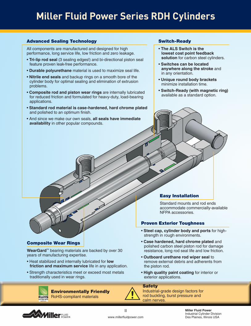
Composite Wear Rings
WearGard™ bearing materials are backed by over 30 years of manufacturing expertise.•Heatstabilizedandinternallylubricatedforlow
friction and maximum service life in any application.•Strengthcharacteristicsmeetorexceedmostmetals
traditionally used in wear rings.
Easy Installation
Standard mounts and rod ends accommodate commercially-available NFPA accessories.
Switch-Ready
•The ALS Switch is the lowest cost point feedback solution for carbon steel cylinders.•Switches can be located
anywhere along the stroke and in any orientation.•Unique round body brackets
minimize installation time.•Switch-Ready (with magnetic ring)
available as a standard option.
Advanced Sealing Technology
All components are manufactured and designed for high performance, long service life, low friction and zero leakage. •Tri-lip rod seal (3 sealing edges!) and bi-directional piston seal
feature proven leak-free performance.•Durable polyurethane material is used to maximize seal life.•Nitrile end seals and backup rings on a smooth bore of the
cylinder body for optimal sealing and elimination of extrusion problems.•Composite rod and piston wear rings are internally lubricated
for reduced friction and formulated for heavy-duty, load-bearing applications.•Standard rod material is case-hardened, hard chrome plated
and polished to an optimum finish.•Andsincewemakeourownseals,all seals have immediate
availability in other popular compounds.
Proven Exterior Toughness
•Steel cap, cylinder body and ports for high-strength in rough environments.•Case hardened, hard chrome plated and
polished carbon steel piston rod for damage resistance, long rod seal life and low friction.•Outboard urethane rod wiper seal to
remove external debris and adherents from the piston rod. •High quality paint coating for interior or
exterior applications.
Miller Fluid Power Series RDH Cylinders
Environmentally FriendlyRoHS-compliant materials
SafetyIndustrial-grade design factors for rod buckling, burst pressure and calm nerves.
www.millerfluidpower.com
Miller Fluid PowerIndustrial Cylinder DivisionDes Plaines, Illinois USA
III
New Value from a Standard Platform
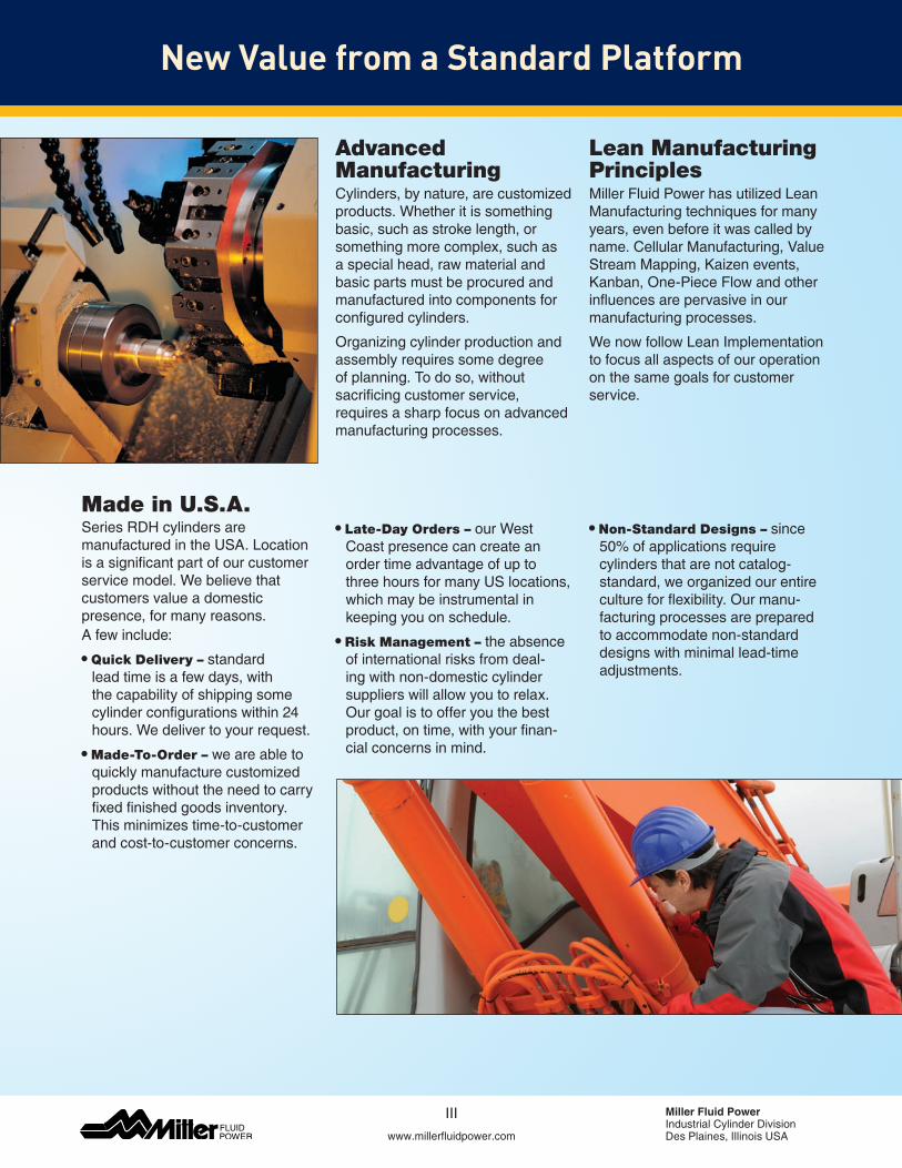
Advanced ManufacturingCylinders, by nature, are customized products.Whetheritissomethingbasic, such as stroke length, or something more complex, such as a special head, raw material and basic parts must be procured and manufactured into components for configured cylinders.
Organizing cylinder production and assembly requires some degree of planning. To do so, without sacrificing customer service, requires a sharp focus on advanced manufacturing processes.
Lean Manufacturing PrinciplesMiller Fluid Power has utilized Lean Manufacturing techniques for many years, even before it was called by name.CellularManufacturing,ValueStream Mapping, Kaizen events, Kanban, One-Piece Flow and other influences are pervasive in our manufacturing processes.
WenowfollowLeanImplementationto focus all aspects of our operation on the same goals for customer service.
Series RDH cylinders are manufactured in the USA. Location is a significant part of our customer servicemodel.Webelievethatcustomers value a domestic presence, for many reasons. A few include:
• Quick Delivery – standard lead time is a few days, with the capability of shipping some cylinder configurations within 24 hours.Wedelivertoyourrequest.
• Made-To-Order – we are able to quickly manufacture customized products without the need to carry fixed finished goods inventory. This minimizes time-to-customer and cost-to-customer concerns.
• Late-Day Orders –ourWestCoast presence can create an order time advantage of up to three hours for many US locations, which may be instrumental in keeping you on schedule.
• Risk Management – the absence of international risks from deal-ing with non-domestic cylinder sup pliers will allow you to relax. Our goal is to offer you the best product, on time, with your finan-cial concerns in mind.
• Non-Standard Designs – since 50% of applications require cylinders that are not catalog-standard, we organized our entire culture for flexibility. Our manu-facturing processes are prepared to accommodate non-standard designs with minimal lead-time adjustments.
Made in U.S.A.
Heavy Duty Hydraulic Roundline CylindersSeries RDH
Miller Fluid PowerIndustrial Cylinder DivisionDes Plaines, Illinois USAwww.millerfluidpower.com
Catalog HY08-M1320-1/NACustomer Service Locations
Customer Service Locations
California 221 Helicopter Circle Corona, CA 92880 Tel.: (951) 280-3800 Fax: (951) 280-3808 Fax: (800) 869-9886
Connecticut 80 Shaker Road Enfield, CT 06082 Tel.: (860) 749-2215 Fax: (800) 323-0105
Georgia 1300 Six Flags Road LithiaSprings,GA30122 Tel.: (770) 819-3400 Fax: (800) 437-3498
Indiana GoodlandPlant 715 South Iroquois Street Goodland,IN47948 Tel.: (219) 297-3182 Fax: (800) 328-8120
Michigan 900 Plymouth Road Plymouth, MI 48170 Tel.: (734) 455-1700 Fax: (734) 455-1007
Oregon 29289 Airport Road Eugene, OR 97402 Tel.: (541) 689-9111 Fax: (541) 688-6771 Fax: (800) 624-7996
Atlanta, GA
IV
Enfield, CT
Corona, CA
Plymouth, MI Goodland, IN
Eugene, OR
Heavy Duty Hydraulic Roundline CylindersSeries RDH
www.millerfluidpower.com
Catalog HY08-M1320-1/NA
1 Miller Fluid PowerIndustrial Cylinder DivisionDes Plaines, Illinois USA
Table of Contents
Table of Contents
Description Page Section
A
B
C
D
Section A – Basic Cylinder Information 2-20Product Specifications . . . . . . . . . . . . . . . . . . . . . . . . . . . . . . . . . . . . . . . . . . . . . 2Available Mounting Styles . . . . . . . . . . . . . . . . . . . . . . . . . . . . . . . . . . . . . . . . . . . 3Custom Options and Modifications . . . . . . . . . . . . . . . . . . . . . . . . . . . . . . . . . . . . 3Features and Benefits . . . . . . . . . . . . . . . . . . . . . . . . . . . . . . . . . . . . . . . . . . . . 4-5Application Checklist . . . . . . . . . . . . . . . . . . . . . . . . . . . . . . . . . . . . . . . . . . . . . . . 6Mounting Styles and Tips for Applying . . . . . . . . . . . . . . . . . . . . . . . . . . . . . . . . . 7How To Order (Series RDH Cylinder Model Code). . . . . . . . . . . . . . . . . . . . . . 8-9Rod End Styles and Dimensions . . . . . . . . . . . . . . . . . . . . . . . . . . . . . . . . . . . . 10Mounting Information for Single Rod Cylinders . . . . . . . . . . . . . . . . . . . . . . .11-19Mounting Information for Double Rod Cylinders . . . . . . . . . . . . . . . . . . . . . . . . . 20
Section B – Cylinder Accessories and Replacement Parts 21-29Cylinder Mounting Accessories . . . . . . . . . . . . . . . . . . . . . . . . . . . . . . . . . . . 21-27Spherical Bearing Mount Accessories . . . . . . . . . . . . . . . . . . . . . . . . . . . . . . . . . 26Linear Alignment Couplers . . . . . . . . . . . . . . . . . . . . . . . . . . . . . . . . . . . . . . . . . . 27Style 55 Piston Rod End Accessories . . . . . . . . . . . . . . . . . . . . . . . . . . . . . . . . . 28Parts Identification / Seal Kits / Service Tools . . . . . . . . . . . . . . . . . . . . . . . . . . .29
Section C – Common Modifications 31-43WaterSubmersible Option . . . . . . . . . . . . . . . . . . . . . . . . . . . . . . . . . . . . . . . 31-32 Hi Load Piston . . . . . . . . . . . . . . . . . . . . . . . . . . . . . . . . . . . . . . . . . . . . . . . . . . . . 33Low Friction Seals . . . . . . . . . . . . . . . . . . . . . . . . . . . . . . . . . . . . . . . . . . . . . . 34-35JP Mount (J Mount with Pilot) . . . . . . . . . . . . . . . . . . . . . . . . . . . . . . . . . . . . . .35 Other Common Modifications . . . . . . . . . . . . . . . . . . . . . . . . . . . . . . . . . . . . . . .36ALS Switch . . . . . . . . . . . . . . . . . . . . . . . . . . . . . . . . . . . . . . . . . . . . . . . . . 37-40CLS-2 Limit Switch . . . . . . . . . . . . . . . . . . . . . . . . . . . . . . . . . . . . . . . . . . . . 41-43
Section D – Engineering Data 45-55Theoretical Push and Pull Forces . . . . . . . . . . . . . . . . . . . . . . . . . . . . . . . . . . .45CylinderWeights . . . . . . . . . . . . . . . . . . . . . . . . . . . . . . . . . . . . . . . . . . . . . . . .46Seal Information . . . . . . . . . . . . . . . . . . . . . . . . . . . . . . . . . . . . . . . . . . . . . 47-48Ports . . . . . . . . . . . . . . . . . . . . . . . . . . . . . . . . . . . . . . . . . . . . . . . . . . . . . . . . .49Stroke Data and Tolerances . . . . . . . . . . . . . . . . . . . . . . . . . . . . . . . . . . . . . . .50Fatigue Life . . . . . . . . . . . . . . . . . . . . . . . . . . . . . . . . . . . . . . . . . . . . . . . . . . . .50MountingGroupsandForceTransfer . . . . . . . . . . . . . . . . . . . . . . . . . . . . . . . .50Stop Tubing . . . . . . . . . . . . . . . . . . . . . . . . . . . . . . . . . . . . . . . . . . . . . . . . . . . .51Piston Rod Selection Data. . . . . . . . . . . . . . . . . . . . . . . . . . . . . . . . . . . . . . 52-53CylinderSafetyGuide . . . . . . . . . . . . . . . . . . . . . . . . . . . . . . . . . . . . . . . . . 54-55
2
Heavy Duty Hydraulic Roundline CylindersSeries RDH
Miller Fluid PowerIndustrial Cylinder DivisionDes Plaines, Illinois USAwww.millerfluidpower.com
Catalog HY08-M1320-1/NA
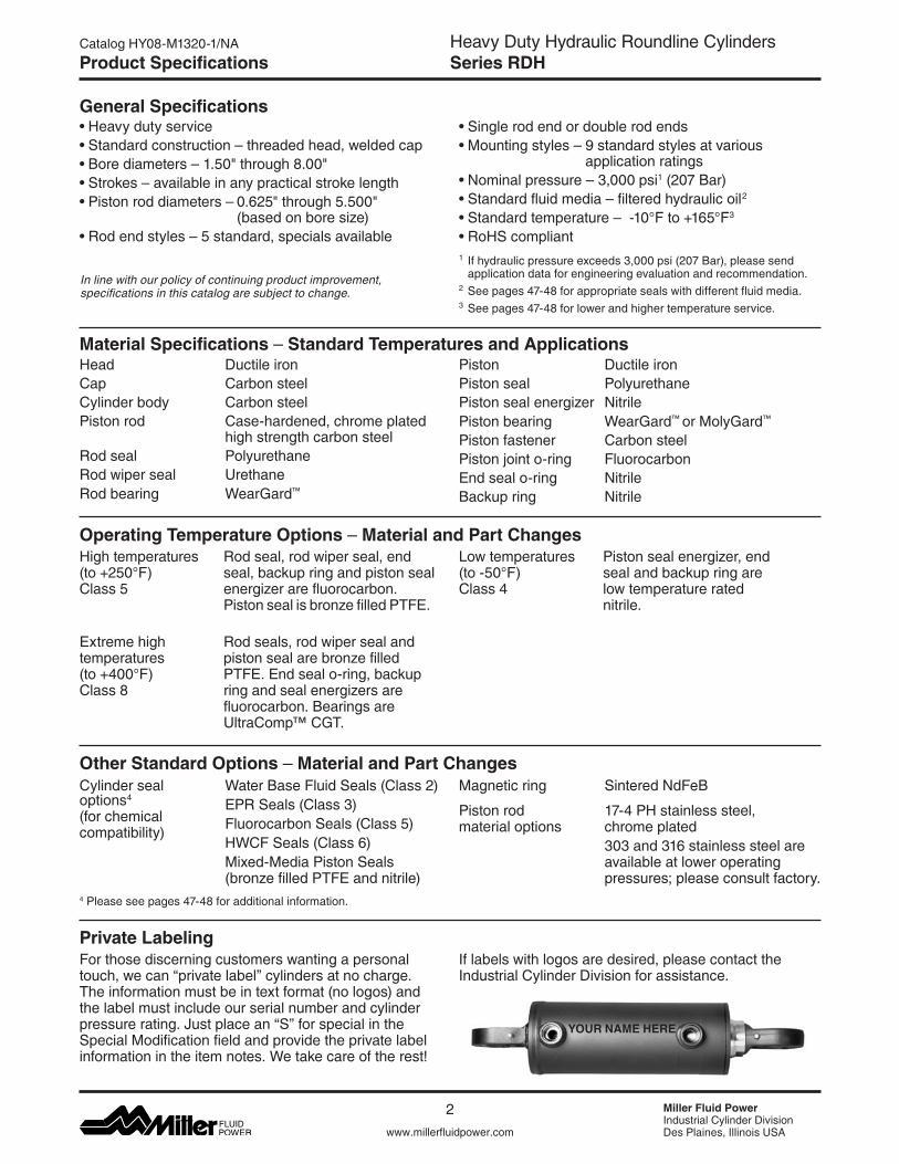
General Specifications•Heavy duty service•Standardconstruction–threadedhead,weldedcap•Borediameters–1.50"through8.00"•Strokes–availableinanypracticalstrokelength•Pistonroddiameters–0.625"through5.500"
(based on bore size)•Rodendstyles–5standard,specialsavailable
•Singlerodendordoublerodends•Mountingstyles–9standardstylesatvarious
application ratings•Nominalpressure–3,000psi1 (207 Bar)•Standardfluidmedia–filteredhydraulicoil2
•Standardtemperature–-10°Fto+165°F3 •RoHScompliant1 If hydraulic pressure exceeds 3,000 psi (207 Bar), please send application data for engineering evaluation and recommendation.2 See pages 47-48 for appropriate seals with different fluid media.3 See pages 47-48 for lower and higher temperature service.
In line with our policy of continuing product improvement, specifications in this catalog are subject to change.
Product Specifications
Head Ductile ironCap Carbon steelCylinder body Carbon steelPiston rod Case-hardened, chrome plated high strength carbon steelRod seal PolyurethaneRod wiper seal UrethaneRodbearing WearGard™
High temperatures Rod seal, rod wiper seal, end (to+250°F) seal,backupringandpistonseal Class 5 energizer are fluorocarbon. Piston seal is bronze filled PTFE.
Extreme high Rod seals, rod wiper seal and temperatures piston seal are bronze filled (to+400°F) PTFE.Endsealo-ring,backupClass 8 ring and seal energizers are fluorocarbon. Bearings are UltraComp™CGT.
Piston Ductile ironPiston seal PolyurethanePiston seal energizer Nitrile Pistonbearing WearGard™ orMolyGard™ Piston fastener Carbon steelPiston joint o-ring FluorocarbonEnd seal o-ring NitrileBackup ring Nitrile
Cylinderseal WaterBaseFluidSeals(Class2)options4 EPR Seals (Class 3)(for chemical Fluorocarbon Seals (Class 5)compatibility)
HWCFSeals(Class6) Mixed-Media Piston Seals (bronze filled PTFE and nitrile)
Low temperatures Piston seal energizer, end (to-50°F) sealandbackupringare Class 4 low temperature rated nitrile.
Magnetic ring Sintered NdFeB
Piston rod 17-4 PH stainless steel, material options chrome plated 303 and 316 stainless steel are available at lower operating pressures; please consult factory.
Material Specifications–Standard Temperatures and Applications
Operating Temperature Options–Material and Part Changes
Other Standard Options–Material and Part Changes
For those discerning customers wanting a personal touch, we can “private label” cylinders at no charge. The information must be in text format (no logos) and the label must include our serial number and cylinder pressure rating. Just place an “S” for special in the Special Modification field and provide the private label informationintheitemnotes.Wetakecareoftherest!
Private LabelingIf labels with logos are desired, please contact the Industrial Cylinder Division for assistance.
YOUR NAME HERE
4 Please see pages 47-48 for additional information.
3
Heavy Duty Hydraulic Roundline CylindersSeries RDH
A
www.millerfluidpower.com
Catalog HY08-M1320-1/NA
Miller Fluid PowerIndustrial Cylinder DivisionDes Plaines, Illinois USA
•SpecialHeads, Caps, Pistons and Mounts•Mount/PortRelocation •Oversize/UndersizePorts •PortThreadStyles•PortBlocks/ValveManifoldandFlowTubing
(at either end)•MultiplePorts•CartridgeValves•AirBleeds•DoubleRodEnd•Oversize/UndersizeRodDiameters•ExtraThickChromePlatedPistonRod•RodMaterials(stainlesssteels,alloysteels,etc.)•RodCoatings(laser-clad,nanoplating,etc.)•NitridedRod•PinnedRodtoPiston•WeldedRodtoPiston•WeldedRodEndAccessory•ExtraWrenchFlats•RodBoot•Crown™Wiper (ExtremeDutyNon-MetallicRodWiper)•MetallicRodWiper
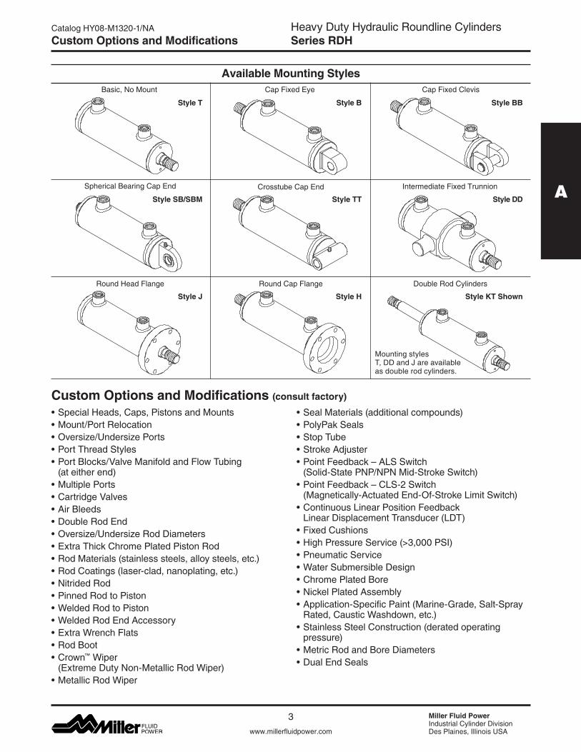
Spherical Bearing Cap End Crosstube Cap End Intermediate Fixed Trunnion
Round Head Flange Round Cap Flange
Style J Style H
Style DD
Style BB
Style SB/SBM Style TT
Double Rod Cylinders
Style KT Shown
Available Mounting StylesCap Fixed Eye
Style B
Cap Fixed Clevis
•SealMaterials(additionalcompounds)•PolyPakSeals•StopTube•StrokeAdjuster•PointFeedback–ALSSwitch
(Solid-State PNP/NPN Mid-Stroke Switch)•PointFeedback–CLS-2Switch
(Magnetically-Actuated End-Of-Stroke Limit Switch)•ContinuousLinearPositionFeedback
Linear Displacement Transducer (LDT)•FixedCushions•HighPressureService(>3,000PSI)•PneumaticService•WaterSubmersibleDesign•ChromePlatedBore•NickelPlatedAssembly•Application-SpecificPaint(Marine-Grade,Salt-SprayRated,CausticWashdown,etc.)•StainlessSteelConstruction(deratedoperating
pressure)•MetricRodandBoreDiameters•DualEndSeals
Style T
Basic, No Mount
Custom Options and Modifications
Mounting styles T, DD and J are available as double rod cylinders.
Custom Options and Modifications (consult factory)
4
Heavy Duty Hydraulic Roundline CylindersSeries RDH
Miller Fluid PowerIndustrial Cylinder DivisionDes Plaines, Illinois USAwww.millerfluidpower.com
Catalog HY08-M1320-1/NA
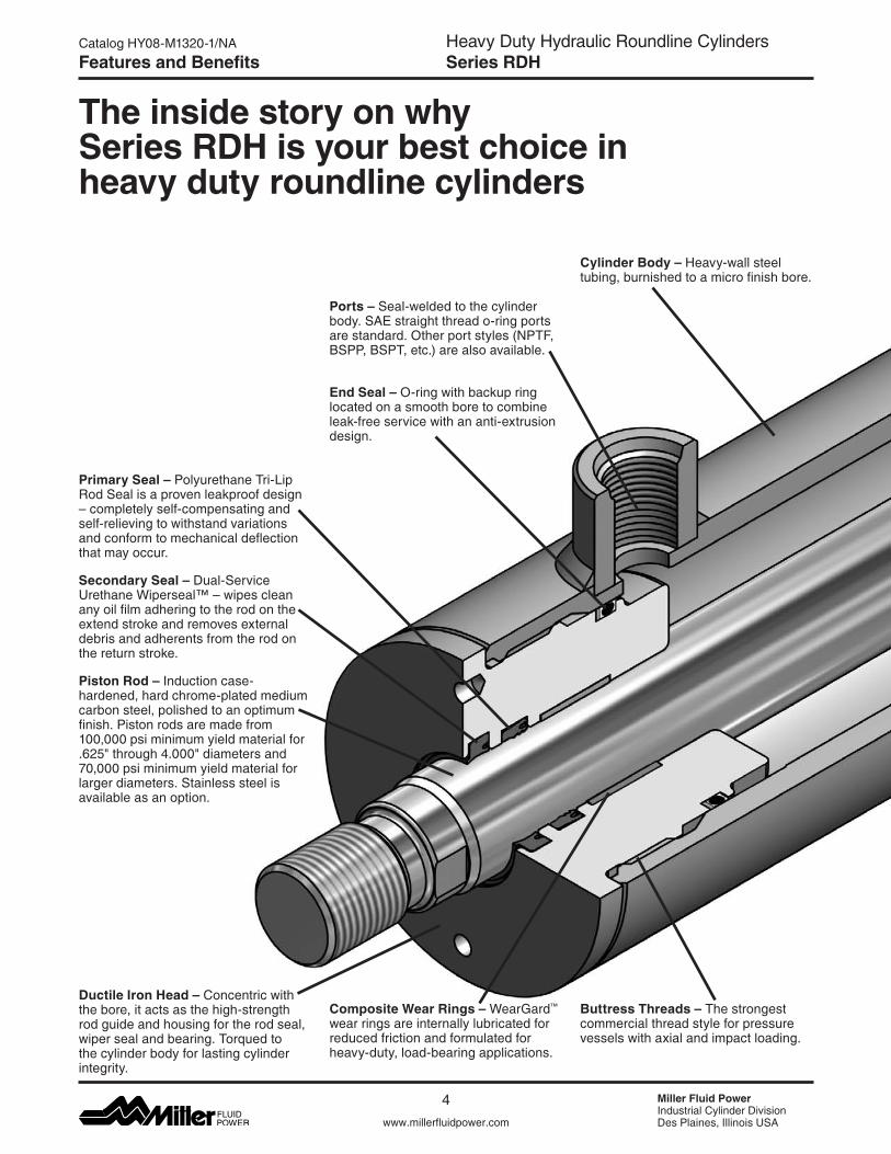
The inside story on why Series RDH is your best choice in heavy duty roundline cylinders
Cylinder Body – Heavy-wall steel tubing, burnished to a micro finish bore.
Ductile Iron Head – Concentric with the bore, it acts as the high-strength rod guide and housing for the rod seal, wiper seal and bearing. Torqued to the cylinder body for lasting cylinder integrity.
Primary Seal – Polyurethane Tri-Lip Rod Seal is a proven leakproof design –completelyself-compensatingandself-relieving to withstand variations and conform to mechanical deflection that may occur.
Secondary Seal – Dual-Service UrethaneWiperseal™–wipescleanany oil film adhering to the rod on the extend stroke and removes external debris and adherents from the rod on the return stroke.
Piston Rod – Induction case-hardened, hard chrome-plated medium carbon steel, polished to an optimum finish. Piston rods are made from 100,000 psi minimum yield material for .625"through4.000"diametersand70,000 psi minimum yield material for larger diameters. Stainless steel is available as an option.
Features and Benefits
End Seal – O-ring with backup ring located on a smooth bore to combine leak-free service with an anti-extrusion design.
Buttress Threads – The strongest commercial thread style for pressure vessels with axial and impact loading.
Composite Wear Rings – WearGard™ wear rings are internally lubricated for reduced friction and formulated for heavy-duty, load-bearing applications.
Ports – Seal-welded to the cylinder body. SAE straight thread o-ring ports are standard. Other port styles (NPTF, BSPP, BSPT, etc.) are also available.
5
Heavy Duty Hydraulic Roundline CylindersSeries RDH
A
www.millerfluidpower.com
Catalog HY08-M1320-1/NA
Miller Fluid PowerIndustrial Cylinder DivisionDes Plaines, Illinois USA
Features and Benefits
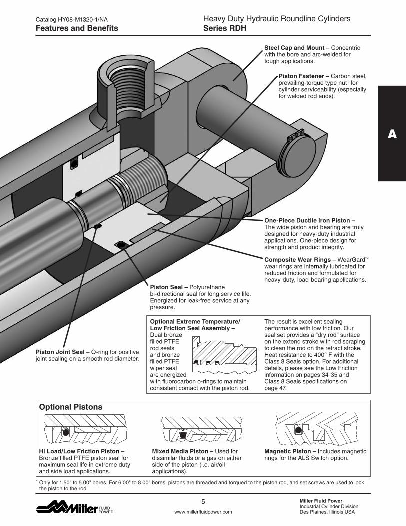
Piston Seal – Polyurethane bi-directional seal for long service life. Energized for leak-free service at any pressure.
Piston Joint Seal – O-ring for positive joint sealing on a smooth rod diameter.
One-Piece Ductile Iron Piston – The wide piston and bearing are truly designed for heavy-duty industrial applications. One-piece design for strength and product integrity.
Composite Wear Rings – WearGard™ wear rings are internally lubricated for reduced friction and formulated for heavy-duty, load-bearing applications.
Optional Extreme Temperature/ Low Friction Seal Assembly – Dual bronze filled PTFE rod seals and bronze filled PTFE wiper seal are energized with fluorocarbon o-rings to maintain consistent contact with the piston rod.
Optional Pistons
Hi Load/Low Friction Piston – Bronze filled PTFE piston seal for maximum seal life in extreme duty and side load applications.
Mixed Media Piston – Used for dissimilar fluids or a gas on either side of the piston (i.e. air/oil applications).
Magnetic Piston – Includes magnetic rings for the ALS Switch option.
Steel Cap and Mount – Concentric with the bore and arc-welded for tough applications.
The result is excellent sealing performance with low friction. Our seal set provides a “dry rod“ surface on the extend stroke with rod scraping to clean the rod on the retract stroke. Heatresistanceto400°FwiththeClass 8 Seals option. For additional details, please see the Low Friction information on pages 34-35 and Class 8 Seals specifications on page 47.
1Onlyfor1.50"to5.00"bores.For6.00"to8.00"bores,pistonsarethreadedandtorquedtothepistonrod,andsetscrewsareusedtolockthe piston to the rod.
Piston Fastener – Carbon steel, prevailing-torque type nut1 for cylinder serviceability (especially for welded rod ends).
6
Heavy Duty Hydraulic Roundline CylindersSeries RDH
Miller Fluid PowerIndustrial Cylinder DivisionDes Plaines, Illinois USAwww.millerfluidpower.com
Catalog HY08-M1320-1/NA
Application ChecklistThe following checklist should be used to select the best possible cylinder for a given application. Additional information can be referenced in the following pages to help assist in this process. In the event that you have additional questions or concerns, or if more information is required, please contact your local distributor or our customer service representatives for assistance.
1. Establish the system requirements • Howheavyistheloadtobemoved? • Whatisthenominaloperatingpressureofthesystem? • Howfardoestheloadhavetomove? • Whatisthespeedatwhichtheloadwillmove? • Whatisthefluidtypeandthetemperaturetowhichthecylinderwillbeexposed?
2. Mounting Style .....................................................................................................................................Pages 3 and 7 • Determinethebestmountingstylefortheapplication.
3. Cylinder Bore and Operating Pressure ......................................................................................................Page 45 • Reviewthetheoreticalpushandpullforcestodeterminetheapplicableboreandroddiametersizes.
4. Piston Rod ...............................................................................................................................................Pages 51-53 • Determinewhatrodsizewillberequiredtoavoidbuckling. • Determineifasingleordoublerodcylinderisrequired. • Determinetherodendstyleandrodendthread. • Willstoptubingberequired? • Isadequatepullforcestillavailableorisalargerborediameternowrequired?
5. Seals .........................................................................................................................................................Pages 47-48 • Selectthepropersealtypeandconfigurationfortheapplication. • Selectthepropersealtoassurefluidandtemperaturecompatibility.
6. Ports ................................................................................................................................................................Page 49 • Selectthebestpossibleportsizeforagivenspeedrequirement. • Selectporttype. • Selectportposition.
7. Piston rod and mounting accessories .................................................................................................Pages 21-28 • Determinehowyouwillattachthecylindertotheload.
8. Optional accessories and modifications ............................................................................................Pages 31-43
Application Checklist
7
Heavy Duty Hydraulic Roundline CylindersSeries RDH
A
www.millerfluidpower.com
Catalog HY08-M1320-1/NA
Miller Fluid PowerIndustrial Cylinder DivisionDes Plaines, Illinois USA
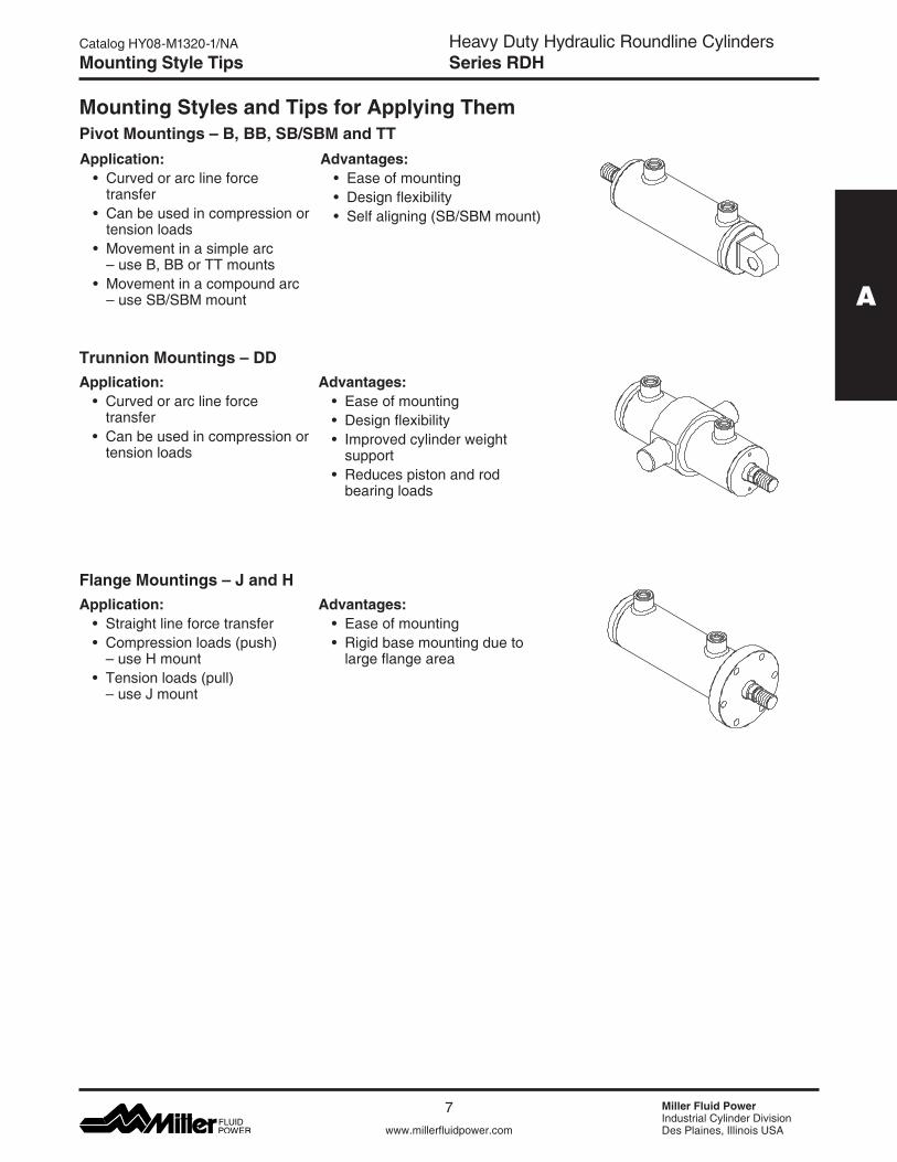
Mounting Styles and Tips for Applying ThemPivot Mountings – B, BB, SB/SBM and TTApplication: • Curvedorarclineforce transfer • Canbeusedincompressionor tension loads • Movementinasimplearc –useB,BBorTTmounts • Movementinacompoundarc –useSB/SBMmount
Advantages: • Easeofmounting • Designflexibility • Selfaligning(SB/SBMmount)
Application: • Curvedorarclineforce transfer • Canbeusedincompressionor tension loads
Trunnion Mountings – DDAdvantages: • Easeofmounting • Designflexibility • Improvedcylinderweight support • Reducespistonandrod bearing loads
Mounting Style Tips
Application: • Straightlineforcetransfer • Compressionloads(push) –useHmount • Tensionloads(pull) –useJmount
Flange Mountings – J and HAdvantages: • Easeofmounting • Rigidbasemountingdueto large flange area
8
Heavy Duty Hydraulic Roundline CylindersSeries RDH
Miller Fluid PowerIndustrial Cylinder DivisionDes Plaines, Illinois USAwww.millerfluidpower.com
Catalog HY08-M1320-1/NA
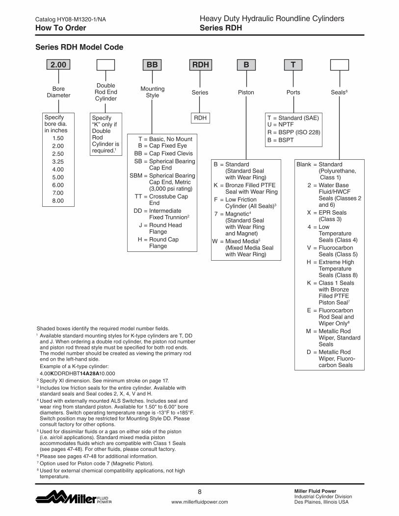
Series RDH Model Code
How To Order
Shaded boxes identify the required model number fields. 1 Available standard mounting styles for K-type cylinders are T, DD andJ.Whenorderingadoublerodcylinder,thepistonrodnumberand piston rod thread style must be specified for both rod ends. The model number should be created as viewing the primary rod end on the left-hand side.
Example of a K-type cylinder: 4.00KDDRDHBT14A28A10.000 2 Specify XI dimension. See minimum stroke on page 17. 3 Includes low friction seals for the entire cylinder. Available with standardsealsandSealcodes2,X,4,VandH.
4 Used with externally mounted ALS Switches. Includes seal and wearringfromstandardpiston.Availablefor1.50"to6.00"borediameters.Switchoperatingtemperaturerangeis-13°Fto+185°F.Switch position may be restricted for Mounting Style DD. Please consult factory for other options.
5 Used for dissimilar fluids or a gas on either side of the piston (i.e. air/oil applications). Standard mixed media piston accommodates fluids which are compatible with Class 1 Seals (see pages 47-48). For other fluids, please consult factory.
6 Please see pages 47-48 for additional information. 7 Option used for Piston code 7 (Magnetic Piston). 8 Used for external chemical compatibility applications, not high
temperature.
2.00
Bore Diameter
Specify bore dia. in inches
1.50 2.00 2.50 3.25 4.00 5.00 6.00 7.008.00
BB RDH B T
Double Rod EndCylinder
Specify “K” only if Double Rod Cylinder is required.1
Mounting Style
T = Basic, No Mount B = Cap Fixed Eye BB = Cap Fixed Clevis SB = Spherical Bearing Cap End SBM = Spherical Bearing Cap End, Metric (3,000 psi rating) TT = Crosstube Cap End DD = Intermediate Fixed Trunnion2
J = Round Head Flange H = Round Cap Flange
Series
RDH
Piston
B = Standard (Standard Seal withWearRing) K = Bronze Filled PTFE SealwithWearRing F = Low Friction Cylinder (All Seals)3
7 = Magnetic4 (Standard Seal withWearRing and Magnet)W =MixedMedia5 (Mixed Media Seal withWearRing)
Ports
T = Standard (SAE) U = NPTFR = BSPP (ISO 228)B = BSPT
Seals6
Blank = Standard (Polyurethane, Class 1) 2 =WaterBase Fluid/HWCF Seals (Classes 2 and 6) X = EPR Seals (Class 3) 4 = Low Temperature Seals (Class 4) V =Fluorocarbon Seals (Class 5) H = Extreme High Temperature Seals (Class 8) K = Class 1 Seals with Bronze Filled PTFE Piston Seal7
E = Fluorocarbon Rod Seal and WiperOnly8
M = Metallic Rod Wiper,Standard Seals D = Metallic Rod Wiper,Fluoro- carbon Seals
9
Heavy Duty Hydraulic Roundline CylindersSeries RDH
A
www.millerfluidpower.com
Catalog HY08-M1320-1/NA
Miller Fluid PowerIndustrial Cylinder DivisionDes Plaines, Illinois USA
How To Order
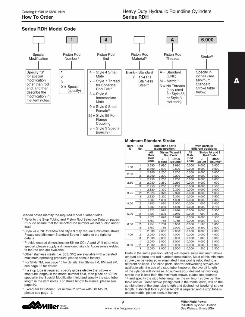
Series RDH Model Code
Special Modification
Piston Rod Number9
1 4 A 6.000
Piston Rod End
1 2 3 0 = Special (specify)
A = Standard (UNF)M = Metric13
N = No Threads (only used for Style 55 or Style 3 rod ends)
Stroke14
Specify in inches (see Minimum Standard Stroke table below)
Piston Rod Material12
Specify"S"for special modifica tion other than rod end, and then describe the modification in the item notes.
Piston Rod Threads
4 = Style 4 Small Male 7 = Style 7 Thread for Spherical Rod Eye10
8 = Style 8 Intermediate Male 9 = Style 9 Small Female10
55 = Style 55 For Flange Coupling 3 = Style 3 Special (specify)11
Blank = Standard Y = 17-4 PH Stainless Steel12
Minimum Standard Stroke
Shaded boxes identify the required model number fields.9 Refer to the Stop Tubing and Piston Rod Selection Data on pages
51-53 to assure that the selected rod number will not buckle under load.
10 Style 7A (UNF threads) and Style 9 may require a minimum stroke. Please see Minimum Standard Stroke in table to the right for details.
11ProvidedesireddimensionsforKK(orCC),AandW.Ifotherwisespecial, please supply a dimensioned sketch. Accessories welded to the rod end are available.
12 Other stainless steels (i.e. 303, 316) are available with a derated maximum operating pressure; please consult factory.
13 For Style 7M, see page 15 for details. For Styles 4M, 8M and 9M, see page 36 for details.
14 If a stop tube is required, specify gross stroke(netstroke+stop tube length) in the model number field, then place an “S” for special in the Special Modification field and specify the stop tube length in the item notes. For stroke length tolerance, please see page 50.
15 Except for DD Mount. For minimum stroke with DD Mount, please see page 17.
Ports in the same position (inline) will require some minimum stroke amount per bore and rod number combination. Most of this minimum stroke can be reduced or eliminated if one port is relocated to a different position. For inline ports, shorter net/working strokes are available with the use of a stop tube; however, the overall length of the cylinder will increase. To achieve your desired net/working stroke that is less than the minimum shown, please see footnote 14 and specify the stop tube length as the minimum stroke per the tableabove.Grossstroke(designatedinthemodelcode)willbethecombination of the stop tube length and desired net (working) stroke length. If shortest total cylinder length is required and a stop tube is unacceptable, please consult factory.
Bore Ø
Rod No.
With inline ports (same position)
With ports in different positions
All Male Rod Ends
Styles 7A and 9 Rod Ends
All Male Rod Ends
Styles 7A and 9 Rod Ends
J Mount
Other Mounts15
J Mount
Other Mounts15
1.50 1 2.690 2.690 2.690 0.000 0.000 0.0002 2.690 2.690 2.690 0.000 0.000 0.000
2.00 1 2.200 2.200 2.200 0.000 0.000 0.0002 2.200 2.200 2.200 0.000 0.000 0.500
2.501 2.250 2.250 2.250 0.000 0.000 0.0002 2.250 2.250 2.250 0.000 0.000 1.0003 2.250 2.250 2.250 0.000 0.000 0.500
3.251 2.320 2.320 2.320 0.000 0.000 0.0002 2.320 2.320 2.320 0.000 0.000 1.0003 2.320 2.320 2.320 0.000 0.000 0.500
4.001 1.880 1.880 1.880 0.000 0.000 0.0002 1.880 1.880 2.000 0.000 1.000 2.0003 1.880 1.880 1.880 0.000 0.000 0.750
5.001 1.820 1.820 1.820 0.000 0.000 0.5002 1.820 1.820 2.250 0.000 1.000 2.2503 1.820 1.820 1.820 0.000 0.000 1.500
6.001 1.750 1.750 1.750 0.000 0.000 1.5002 1.750 1.750 3.000 0.000 1.500 3.0003 1.750 1.750 2.000 0.000 0.500 2.000
7.001 2.000 2.000 2.000 0.000 0.000 2.0002 2.000 2.000 4.000 0.000 2.000 4.0003 2.000 2.000 3.000 0.000 1.000 3.000
8.001 2.000 2.000 2.000 0.000 0.000 2.0002 2.000 3.000 5.000 0.000 3.000 5.0003 2.000 2.000 3.500 0.000 1.500 3.500
10
Heavy Duty Hydraulic Roundline CylindersSeries RDH
Miller Fluid PowerIndustrial Cylinder DivisionDes Plaines, Illinois USAwww.millerfluidpower.com
Catalog HY08-M1320-1/NA
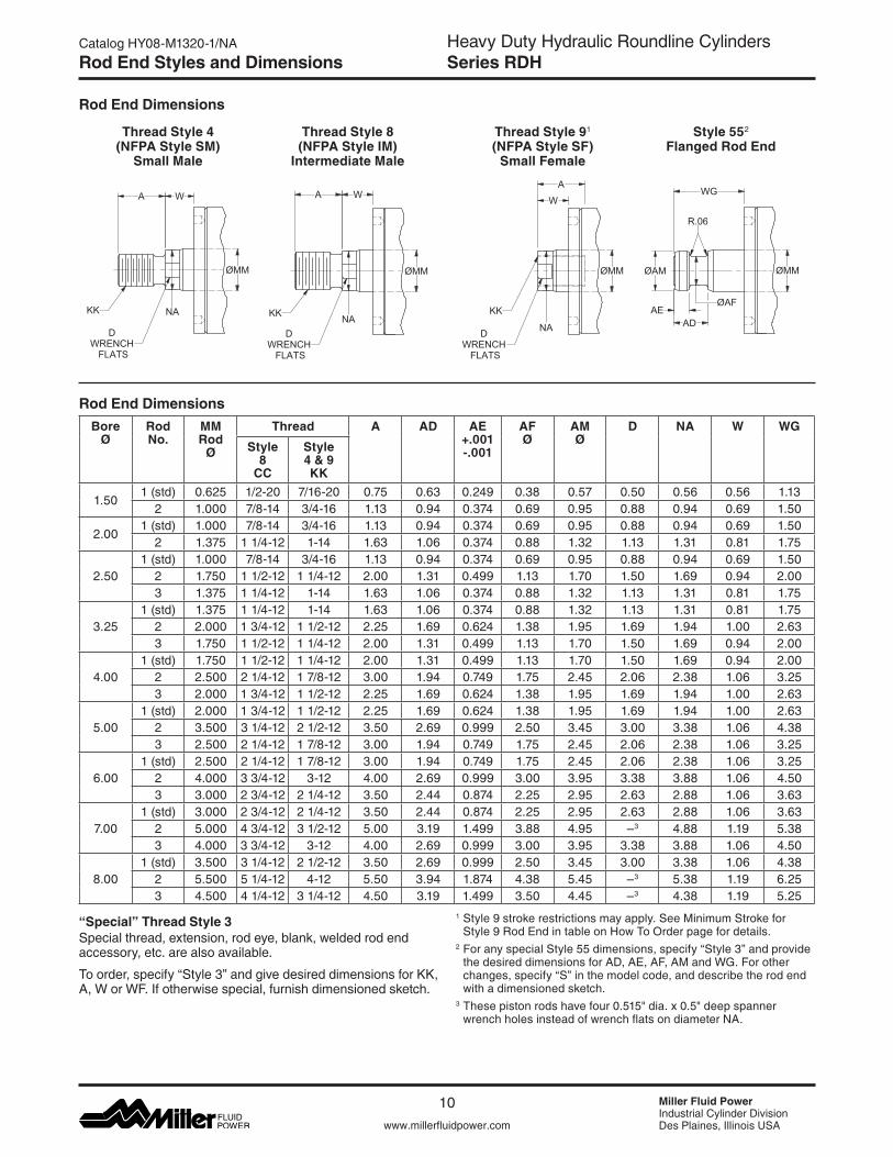
Rod End Dimensions
Thread Style 8 (NFPA Style IM)
Intermediate Male
Thread Style 4 (NFPA Style SM)
Small Male
“Special” Thread Style 3Special thread, extension, rod eye, blank, welded rod end accessory, etc. are also available.
To order, specify “Style 3” and give desired dimensions for KK, A,WorWF.Ifotherwisespecial,furnishdimensionedsketch.
Rod End Styles and Dimensions
Rod End Dimensions
Style 552 Flanged Rod End
Thread Style 91 (NFPA Style SF)
Small Female
A W
DWRENCH
FLATS
KK NA
ØMM
Bore Ø
Rod No.
MM Rod
Ø
Thread A AD AE +.001 -.001
AF Ø
AM Ø
D NA W WG
Style 8
CC
Style 4 & 9 KK
1.501 (std) 0.625 1/2-20 7/16-20 0.75 0.63 0.249 0.38 0.57 0.50 0.56 0.56 1.13
2 1.000 7/8-14 3/4-16 1.13 0.94 0.374 0.69 0.95 0.88 0.94 0.69 1.50
2.001 (std) 1.000 7/8-14 3/4-16 1.13 0.94 0.374 0.69 0.95 0.88 0.94 0.69 1.50
2 1.375 1 1/4-12 1-14 1.63 1.06 0.374 0.88 1.32 1.13 1.31 0.81 1.75
2.501 (std) 1.000 7/8-14 3/4-16 1.13 0.94 0.374 0.69 0.95 0.88 0.94 0.69 1.50
2 1.750 1 1/2-12 1 1/4-12 2.00 1.31 0.499 1.13 1.70 1.50 1.69 0.94 2.003 1.375 1 1/4-12 1-14 1.63 1.06 0.374 0.88 1.32 1.13 1.31 0.81 1.75
3.251 (std) 1.375 1 1/4-12 1-14 1.63 1.06 0.374 0.88 1.32 1.13 1.31 0.81 1.75
2 2.000 1 3/4-12 1 1/2-12 2.25 1.69 0.624 1.38 1.95 1.69 1.94 1.00 2.633 1.750 1 1/2-12 1 1/4-12 2.00 1.31 0.499 1.13 1.70 1.50 1.69 0.94 2.00
4.001 (std) 1.750 1 1/2-12 1 1/4-12 2.00 1.31 0.499 1.13 1.70 1.50 1.69 0.94 2.00
2 2.500 2 1/4-12 1 7/8-12 3.00 1.94 0.749 1.75 2.45 2.06 2.38 1.06 3.253 2.000 1 3/4-12 1 1/2-12 2.25 1.69 0.624 1.38 1.95 1.69 1.94 1.00 2.63
5.001 (std) 2.000 1 3/4-12 1 1/2-12 2.25 1.69 0.624 1.38 1.95 1.69 1.94 1.00 2.63
2 3.500 3 1/4-12 2 1/2-12 3.50 2.69 0.999 2.50 3.45 3.00 3.38 1.06 4.383 2.500 2 1/4-12 1 7/8-12 3.00 1.94 0.749 1.75 2.45 2.06 2.38 1.06 3.25
6.001 (std) 2.500 2 1/4-12 1 7/8-12 3.00 1.94 0.749 1.75 2.45 2.06 2.38 1.06 3.25
2 4.000 3 3/4-12 3-12 4.00 2.69 0.999 3.00 3.95 3.38 3.88 1.06 4.503 3.000 2 3/4-12 2 1/4-12 3.50 2.44 0.874 2.25 2.95 2.63 2.88 1.06 3.63
7.001 (std) 3.000 2 3/4-12 2 1/4-12 3.50 2.44 0.874 2.25 2.95 2.63 2.88 1.06 3.63
2 5.000 4 3/4-12 3 1/2-12 5.00 3.19 1.499 3.88 4.95 –3 4.88 1.19 5.383 4.000 3 3/4-12 3-12 4.00 2.69 0.999 3.00 3.95 3.38 3.88 1.06 4.50
8.001 (std) 3.500 3 1/4-12 2 1/2-12 3.50 2.69 0.999 2.50 3.45 3.00 3.38 1.06 4.38
2 5.500 5 1/4-12 4-12 5.50 3.94 1.874 4.38 5.45 –3 5.38 1.19 6.253 4.500 4 1/4-12 3 1/4-12 4.50 3.19 1.499 3.50 4.45 –3 4.38 1.19 5.25
W
KK
NA
ØMM
DWRENCH
FLATS
AWG
ØAFAE
AD
ØAM
R.06
ØMM
1 Style 9 stroke restrictions may apply. See Minimum Stroke for Style 9 Rod End in table on How To Order page for details.
2 For any special Style 55 dimensions, specify “Style 3” and provide thedesireddimensionsforAD,AE,AF,AMandWG.Forotherchanges, specify “S” in the model code, and describe the rod end with a dimensioned sketch.
3 Thesepistonrodshavefour0.515"dia.x0.5"deepspannerwrench holes instead of wrench flats on diameter NA.
A W
NAKK
DWRENCH
FLATS
ØMM

11
Heavy Duty Hydraulic Roundline CylindersSeries RDH
A
www.millerfluidpower.com
Catalog HY08-M1320-1/NA
Miller Fluid PowerIndustrial Cylinder DivisionDes Plaines, Illinois USA
Mounting Information – 1.50" to 8.00" Bore
Basic, No MountStyle T
Table 1 – Dimensional and Mounting Data
Table 2 – Dimensional and Mounting Data
EE
HD
ØE
LB + STROKE
P + STROKEY
W
ZJ + STROKE
ØMM
Bore Ø
Rod No. E Ø
EE HD Add Stroke
NPTF1 SAE2 LB P
1.501 (std) 1.88 3/8 6 1.60 3.56 1.19
2 1.88 3/8 6 1.60 3.94 1.192.00 – 2.38 1/2 8 2.04 4.81 1.932.50 – 3.00 1/2 8 2.37 5.25 1.883.25 – 3.88 3/4 12 2.81 6.00 2.064.00 – 4.61 3/4 12 3.20 6.50 2.505.00 – 5.75 3/4 12 3.79 7.12 2.566.00 – 7.00 1 16 4.58 8.37 3.007.00 – 8.00 1 1/4 20 5.11 9.00 3.258.00 – 9.25 1 1/4 20 5.76 9.50 3.25
1 NPTF ports are available for no additional charge 2 SAE straight thread o-ring ports are standard
Bore Ø
Rod No. MM Rod Ø
W Y Add Stroke
ZJ
1.501 (std) 0.625 0.56 2.12 4.12
2 1.000 0.69 2.62 4.63
2.001 (std) 1.000 0.69 2.51 5.50
2 1.375 0.81 2.63 5.62
2.501 (std) 1.000 0.69 2.69 5.94
2 1.750 0.94 2.94 6.193 1.375 0.81 2.81 6.06
3.251 (std) 1.375 0.81 3.07 6.81
2 2.000 1.00 3.25 7.003 1.750 0.94 3.19 6.94
4.001 (std) 1.750 0.94 3.39 7.44
2 2.500 1.06 3.52 7.563 2.000 1.00 3.46 7.50
5.001 (std) 2.000 1.00 3.70 8.12
2 3.500 1.06 3.76 8.183 2.500 1.06 3.76 8.18
6.001 (std) 2.500 1.06 4.24 9.43
2 4.000 1.06 4.24 9.433 3.000 1.06 4.24 9.43
7.001 (std) 3.000 1.06 4.25 10.06
2 5.000 1.19 4.38 10.193 4.000 1.06 4.25 10.06
8.001 (std) 3.500 1.06 4.44 10.56
2 5.500 1.19 4.56 10.683 4.500 1.19 4.56 10.68
12
Heavy Duty Hydraulic Roundline CylindersSeries RDH
Miller Fluid PowerIndustrial Cylinder DivisionDes Plaines, Illinois USAwww.millerfluidpower.com
Catalog HY08-M1320-1/NAMounting Information – 1.50" to 8.00" Bore
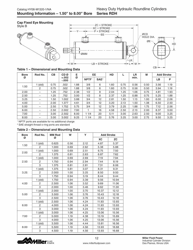
Cap Fixed Eye MountingStyle B
Table 1 – Dimensional and Mounting Data
Table 2 – Dimensional and Mounting Data
ZC + STROKE
LB + STROKE
P + STROKEY
W
ØCDHOLE DIA.
LCB
HDØE
EE
XC + STROKE
LRM
ØMM
1 NPTF ports are available for no additional charge 2 SAE straight thread o-ring ports are standard
Bore Ø
Rod No. CB CD Ø +.002 -.000
E Ø
EE HD L LR min.
M Add Stroke
NPTF1 SAE2 LB P
1.501 (std) 0.75 .502 1.88 3/8 6 1.60 0.75 0.56 0.50 3.56 1.19
2 0.75 .502 1.88 3/8 6 1.60 0.75 0.56 0.50 3.94 1.192.00 – 1.25 .752 2.38 1/2 8 2.04 1.25 1.06 0.75 4.81 1.932.50 – 1.25 .752 3.00 1/2 8 2.37 1.25 0.88 0.75 5.25 1.883.25 – 1.50 1.002 3.88 3/4 12 2.81 1.50 1.13 1.00 6.00 2.064.00 – 2.00 1.377 4.61 3/4 12 3.20 2.13 1.50 1.38 6.50 2.505.00 – 2.50 1.752 5.75 3/4 12 3.79 2.25 1.88 1.75 7.12 2.566.00 – 2.50 2.002 7.00 1 16 4.58 2.50 2.13 2.00 8.37 3.007.00 – 3.00 2.502 8.00 1 1/4 20 5.11 3.00 2.63 2.50 9.00 3.258.00 – 3.00 3.002 9.25 1 1/4 20 5.76 3.25 3.00 2.75 9.50 3.25
Bore Ø
Rod No. MM Rod Ø
W Y Add Stroke
XC ZC
1.501 (std) 0.625 0.56 2.12 4.87 5.37
2 1.000 0.69 2.62 5.38 5.88
2.001 (std) 1.000 0.69 2.51 6.75 7.50
2 1.375 0.81 2.63 6.87 7.62
2.501 (std) 1.000 0.69 2.69 7.19 7.94
2 1.750 0.94 2.94 7.44 8.193 1.375 0.81 2.81 7.31 8.06
3.251 (std) 1.375 0.81 3.07 8.31 9.31
2 2.000 1.00 3.25 8.50 9.503 1.750 0.94 3.19 8.44 9.44
4.001 (std) 1.750 0.94 3.39 9.56 10.94
2 2.500 1.06 3.52 9.69 11.063 2.000 1.00 3.46 9.62 11.00
5.001 (std) 2.000 1.00 3.70 10.37 12.12
2 3.500 1.06 3.76 10.43 12.183 2.500 1.06 3.76 10.43 12.18
6.001 (std) 2.500 1.06 4.24 11.93 13.93
2 4.000 1.06 4.24 11.93 13.933 3.000 1.06 4.24 11.93 13.93
7.001 (std) 3.000 1.06 4.25 13.06 15.56
2 5.000 1.19 4.38 13.19 15.693 4.000 1.06 4.25 13.06 15.56
8.001 (std) 3.500 1.06 4.44 13.81 16.56
2 5.500 1.19 4.56 13.93 16.683 4.500 1.19 4.56 13.93 16.68
13
Heavy Duty Hydraulic Roundline CylindersSeries RDH
A
www.millerfluidpower.com
Catalog HY08-M1320-1/NA
Miller Fluid PowerIndustrial Cylinder DivisionDes Plaines, Illinois USA
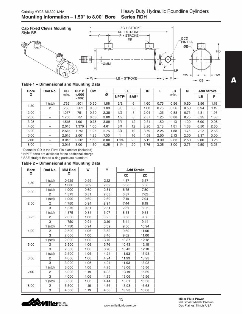
Cap Fixed Clevis Mounting Style BB
Mounting Information – 1.50" to 8.00" Bore
Table 1 – Dimensional and Mounting Data
Table 2 – Dimensional and Mounting Data
CW CWCB
ØEHD
ZC + STROKEXC + STROKE
LB + STROKE
P + STROKEY
W L
EE
M
LR
ØMM
ØCDPIN DIA.
Bore Ø
Rod No. CB min.
CD1 Ø +.000 -.002
CW E Ø
EE HD L LR min.
M Add Stroke
NPTF2 SAE3 LB P
1.501 (std) .765 .501 0.50 1.88 3/8 6 1.60 0.75 0.56 0.50 3.56 1.19
2 .765 .501 0.50 1.88 3/8 6 1.60 0.75 0.56 0.50 3.94 1.192.00 – 1.077 .751 0.50 2.38 1/2 8 2.04 1.25 0.88 0.75 4.81 1.932.50 – 1.265 .751 0.63 3.00 1/2 8 2.37 1.25 0.88 0.75 5.25 1.883.25 – 1.515 1.001 0.75 3.88 3/4 12 2.81 1.50 1.13 1.00 6.00 2.064.00 – 2.015 1.376 1.00 4.61 3/4 12 3.20 2.13 1.81 1.38 6.50 2.505.00 – 2.515 1.751 1.25 5.75 3/4 12 3.79 2.25 1.88 1.75 7.12 2.566.00 – 2.515 2.001 1.25 7.00 1 16 4.58 2.50 2.13 2.00 8.37 3.007.00 – 3.015 2.501 1.50 8.00 1 1/4 20 5.11 3.00 2.63 2.50 9.00 3.258.00 – 3.015 3.001 1.50 9.25 1 1/4 20 5.76 3.25 3.00 2.75 9.50 3.25
1 Diameter CD is the Pivot Pin diameter (included) 2 NPTF ports are available for no additional charge 3 SAE straight thread o-ring ports are standard
Bore Ø
Rod No. MM Rod Ø
W Y Add Stroke
XC ZC
1.501 (std) 0.625 0.56 2.12 4.87 5.37
2 1.000 0.69 2.62 5.38 5.88
2.001 (std) 1.000 0.69 2.51 6.75 7.50
2 1.375 0.81 2.63 6.87 7.62
2.501 (std) 1.000 0.69 2.69 7.19 7.94
2 1.750 0.94 2.94 7.44 8.193 1.375 0.81 2.81 7.31 8.06
3.251 (std) 1.375 0.81 3.07 8.31 9.31
2 2.000 1.00 3.25 8.50 9.503 1.750 0.94 3.19 8.44 9.44
4.001 (std) 1.750 0.94 3.39 9.56 10.94
2 2.500 1.06 3.52 9.69 11.063 2.000 1.00 3.46 9.62 11.00
5.001 (std) 2.000 1.00 3.70 10.37 12.12
2 3.500 1.06 3.76 10.43 12.183 2.500 1.06 3.76 10.43 12.18
6.001 (std) 2.500 1.06 4.24 11.93 13.93
2 4.000 1.06 4.24 11.93 13.933 3.000 1.06 4.24 11.93 13.93
7.001 (std) 3.000 1.06 4.25 13.06 15.56
2 5.000 1.19 4.38 13.19 15.693 4.000 1.06 4.25 13.06 15.56
8.001 (std) 3.500 1.06 4.44 13.81 16.56
2 5.500 1.19 4.56 13.93 16.683 4.500 1.19 4.56 13.93 16.68
14
Heavy Duty Hydraulic Roundline CylindersSeries RDH
Miller Fluid PowerIndustrial Cylinder DivisionDes Plaines, Illinois USAwww.millerfluidpower.com
Catalog HY08-M1320-1/NA
A
X
A
X
XL + STROKE
XL + STROKE
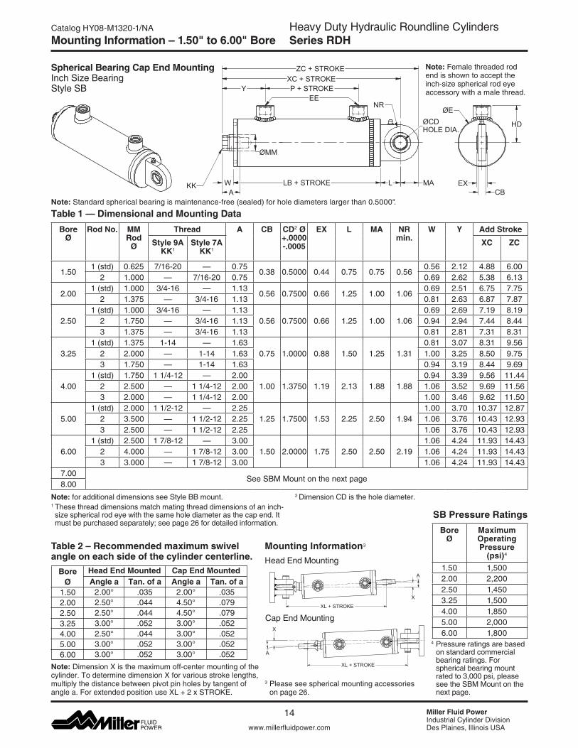
Mounting Information3
Head End Mounting
Note: for additional dimensions see Style BB mount. 1 These thread dimensions match mating thread dimensions of an inch-size spherical rod eye with the same hole diameter as the cap end. It must be purchased separately; see page 26 for detailed information.
Note: Dimension X is the maximum off-center mounting of the cylinder. To determine dimension X for various stroke lengths, multiply the distance between pivot pin holes by tangent of anglea.ForextendedpositionuseXL+2xSTROKE.
Bore Ø
1.502.002.503.254.005.006.00
Angle a2.00°2.50°2.50°3.00°2.50°3.00°3.00°
Tan. of a.035.044.044.052.044.052.052
Angle a2.00°4.50°4.50°3.00°3.00°3.00°3.00°
Tan. of a.035.079.079.052.052.052.052
Table 1 — Dimensional and Mounting Data
Cap End Mounting
Table 2 – Recommended maximum swivel angle on each side of the cylinder centerline.
Mounting Information – 1.50" to 6.00" Bore
Spherical Bearing Cap End MountingInch Size BearingStyle SB
2 Dimension CD is the hole diameter.
Head End Mounted Cap End Mounted
P + STROKE
LB + STROKE L MA
HD
EX
ØEEE
NR
XC + STROKEZC + STROKE
WA
KKCB
Y
ØMM
ØCDHOLE DIA.
Bore Ø
Rod No. MM Rod
Ø
Thread A CB CD2 Ø +.0000 -.0005
EX L MA NR min.
W Y Add Stroke
Style 9A KK1
Style 7A KK1
XC ZC
1.501 (std) 0.625 7/16-20 — 0.75
0.38 0.5000 0.44 0.75 0.75 0.560.56 2.12 4.88 6.00
2 1.000 — 7/16-20 0.75 0.69 2.62 5.38 6.13
2.001 (std) 1.000 3/4-16 — 1.13
0.56 0.7500 0.66 1.25 1.00 1.060.69 2.51 6.75 7.75
2 1.375 — 3/4-16 1.13 0.81 2.63 6.87 7.87
2.501 (std) 1.000 3/4-16 — 1.13
0.56 0.7500 0.66 1.25 1.00 1.060.69 2.69 7.19 8.19
2 1.750 — 3/4-16 1.13 0.94 2.94 7.44 8.443 1.375 — 3/4-16 1.13 0.81 2.81 7.31 8.31
3.251 (std) 1.375 1-14 — 1.63
0.75 1.0000 0.88 1.50 1.25 1.310.81 3.07 8.31 9.56
2 2.000 — 1-14 1.63 1.00 3.25 8.50 9.753 1.750 — 1-14 1.63 0.94 3.19 8.44 9.69
4.001 (std) 1.750 1 1/4-12 — 2.00
1.00 1.3750 1.19 2.13 1.88 1.880.94 3.39 9.56 11.44
2 2.500 — 1 1/4-12 2.00 1.06 3.52 9.69 11.563 2.000 — 1 1/4-12 2.00 1.00 3.46 9.62 11.50
5.001 (std) 2.000 1 1/2-12 — 2.25
1.25 1.7500 1.53 2.25 2.50 1.941.00 3.70 10.37 12.87
2 3.500 — 1 1/2-12 2.25 1.06 3.76 10.43 12.933 2.500 — 1 1/2-12 2.25 1.06 3.76 10.43 12.93
6.001 (std) 2.500 1 7/8-12 — 3.00
1.50 2.0000 1.75 2.50 2.50 2.191.06 4.24 11.93 14.43
2 4.000 — 1 7/8-12 3.00 1.06 4.24 11.93 14.433 3.000 — 1 7/8-12 3.00 1.06 4.24 11.93 14.43
7.00See SBM Mount on the next page
8.00
Bore Ø
Maximum Operating Pressure
(psi)4
1.50 1,5002.00 2,2002.50 1,4503.25 1,5004.00 1,8505.00 2,0006.00 1,800
SB Pressure Ratings
Note: Female threaded rod end is shown to accept the inch-size spherical rod eye accessory with a male thread.
4 Pressure ratings are based on standard commercial bearing ratings. For spherical bearing mount rated to 3,000 psi, please see the SBM Mount on the next page.
3 Please see spherical mounting accessories on page 26.
Note:Standardsphericalbearingismaintenance-free(sealed)forholediameterslargerthan0.5000".

15
Heavy Duty Hydraulic Roundline CylindersSeries RDH
A
www.millerfluidpower.com
Catalog HY08-M1320-1/NA
Miller Fluid PowerIndustrial Cylinder DivisionDes Plaines, Illinois USA
Although the standard SB Mount has derated pressure ratings below 3,000 psi, the SBM Mount is a standard spherical bearing mount rated at 3,000 psi1. Please note that the SBM Mount has slightly different lug dimensions
P + STROKE
LB + STROKE L MA
HD
EX
ØEEE
NR
XC + STROKEZC + STROKE
W
A
KKCB
Y
ØMM
ØCDHOLE DIA.
Note: for additional dimensions, please see Style SB Mount.For recommended maximum swivel angles, please see Table 2 and sketch on the previous page.1 Pressure ratings based on standard commercial bearing ratings. The7.00"boreSBMMounthasamaximumpressureratingof2,450 psi.
Table 1 — Dimensional and Mounting Data
Mounting Information - 1.50" to 8.00" Bore
and a metric bearing size. Metric spherical rod eyes are available on page 26. Information on additional metric accessories is available from the MHP Series ISO Hydraulic Tie Rod Cylinder catalog, or consult factory.
2 These thread dimensions match mating thread dimensions of a metric spherical rod eye with the same hole diameter as the cap end. It must be purchased separately; see page 26 for detailed information.
3 Dimension CD is the hole diameter.
Note: Male threaded rod end is shown to accept the metric spherical rod eye accessory with a female thread.
Note: Standard spherical bearing is maintenance-free (sealed).
Bore Ø
Rod No. MM Rod
Ø
A2 Thread Length (mm)
KK2 Thread
Style 7M Male
W Y Add Stroke Dimensions at cap end (mm)
XC ZC CB (mm)
CD3 Ø (mm)
EX (mm)
L (mm)
MA (mm)
NR min. (mm)
1.501 (std) 0.625 0.71 (18) M14X1.5 0.56 2.12 5.11 6.25 0.51
(13)0.7874 -.0005
(20 -.012)0.63 (16)
0.98 (25)
1.14 (29)
0.87 (22)2 1.000 0.71 (18) M14X1.5 0.69 2.62 5.61 6.75
2.001 (std) 1.000 0.87 (22) M16X1.5 0.69 2.51 6.72 8.02 0.67
(17)0.9843 -.0005
(25 -.012)0.79 (20)
1.22 (31)
1.30 (33)
1.10 (28)2 1.375 0.87 (22) M16X1.5 0.81 2.63 6.84 8.14
2.501 (std) 1.000 1.10 (28) M20X1.5 0.69 2.69 7.43 9.01
0.75 (19)
1.1811 -.0005 (30 -.012)
0.87 (22)
1.50 (38)
1.57 (40)
1.38 (35)2 1.750 1.10 (28) M20X1.5 0.94 2.94 7.68 9.26
3 1.375 1.10 (28) M20X1.5 0.81 2.81 7.56 9.13
3.251 (std) 1.375 1.42 (36) M27X2 0.81 3.07 8.70 10.67
0.91 (23)
1.5748 -.0005 (40 -.012)
1.10 (28)
1.89 (48)
1.97 (50)
1.73 (44)2 2.000 1.42 (36) M27X2 1.00 3.25 8.89 10.86
3 1.750 1.42 (36) M27X2 0.94 3.19 8.83 10.80
4.001 (std) 1.750 1.77 (45) M33X2 0.94 3.39 9.72 12.16
1.18 (30)
1.9685 -.0005 (50 -.012)
1.38 (35)
2.28 (58)
2.44 (62)
2.13 (54)2 2.500 1.77 (45) M33X2 1.06 3.52 9.84 12.28
3 2.000 1.77 (45) M33X2 1.00 3.46 9.78 12.22
5.001 (std) 2.000 2.20 (56) M42X2 1.00 3.70 10.95 14.10
1.50 (38)
2.3622 -.0006 (60 -.015)
1.73 (44)
2.83 (72)
3.15 (80)
2.68 (68)2 3.500 2.20 (56) M42X2 1.06 3.76 11.01 14.16
3 2.500 2.20 (56) M42X2 1.06 3.76 11.01 14.16
6.001 (std) 2.500 2.48 (63) M48X2 1.06 4.24 13.05 16.99
1.85 (47)
3.1496 -.0006 (80 -.015)
2.17 (55)
3.62 (92)
3.94 (100)
3.46 (88)2 4.000 2.48 (63) M48X2 1.06 4.24 13.05 16.99
3 3.000 2.48 (63) M48X2 1.06 4.24 13.05 16.99
7.001
1 (std) 3.000 2.48 (63) M48X2 1.06 4.25 13.68 17.621.85 (47)
3.1496 -.0006 (80 -.015)
2.17 (55)
3.62 (92)
3.94 (100)
3.46 (88)2 5.000 2.48 (63) M48X2 1.19 4.38 13.81 17.75
3 4.000 2.48 (63) M48X2 1.06 4.25 13.68 17.62
8.001 (std) 3.500 3.35 (85) M64X3 1.06 4.44 15.12 19.85
2.24 (57)
3.9370 -.0008 (100 -.020)
2.76 (70)
4.57 (116)
4.72 (120)
4.37 (111)2 5.500 3.35 (85) M64X3 1.19 4.56 15.25 19.97
3 4.500 3.35 (85) M64X3 1.19 4.56 15.25 19.97
Spherical Bearing Cap End MountingMetric Size BearingStyle SBM
16
Heavy Duty Hydraulic Roundline CylindersSeries RDH
Miller Fluid PowerIndustrial Cylinder DivisionDes Plaines, Illinois USAwww.millerfluidpower.com
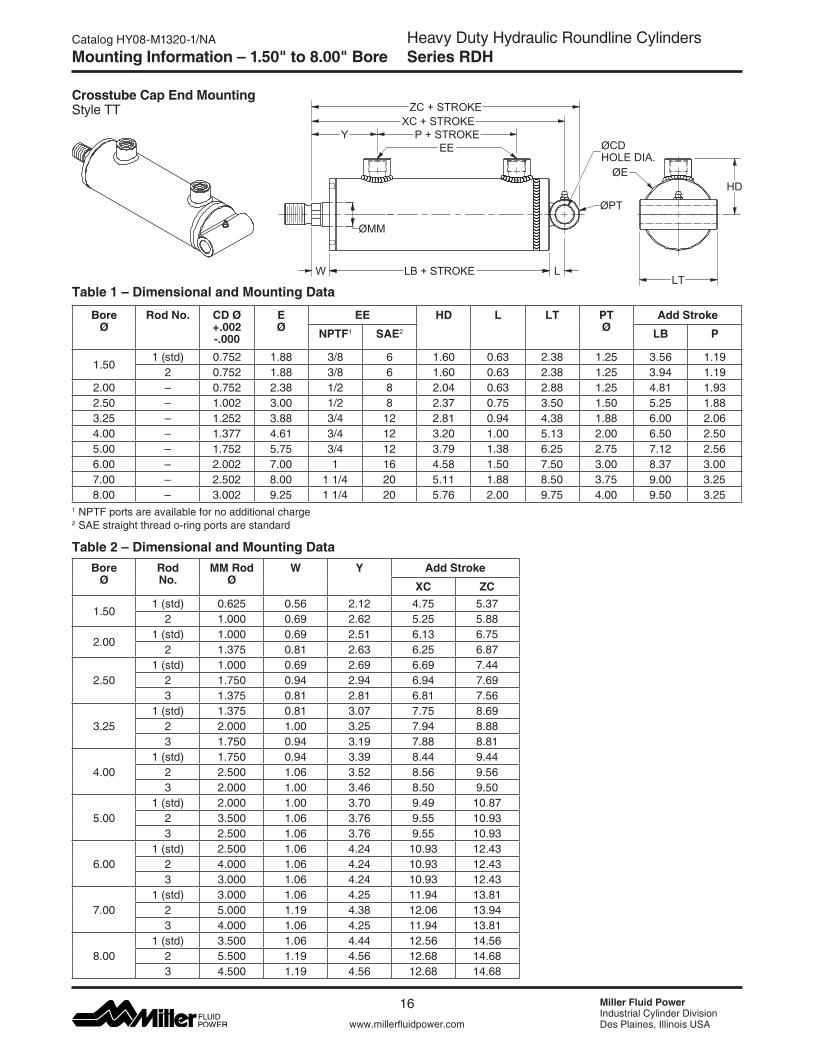
Catalog HY08-M1320-1/NAMounting Information – 1.50" to 8.00" Bore
Crosstube Cap End Mounting Style TT
Table 1 – Dimensional and Mounting Data
Table 2 – Dimensional and Mounting Data
EE
LT
HDØE
XC + STROKE
LB + STROKE
ZC + STROKE
P + STROKEY
W
ØPT
L
ØMM
ØCDHOLE DIA.
Bore Ø
Rod No. CD Ø +.002 -.000
E Ø
EE HD L LT PT Ø
Add Stroke
NPTF1 SAE2 LB P
1.501 (std) 0.752 1.88 3/8 6 1.60 0.63 2.38 1.25 3.56 1.19
2 0.752 1.88 3/8 6 1.60 0.63 2.38 1.25 3.94 1.192.00 – 0.752 2.38 1/2 8 2.04 0.63 2.88 1.25 4.81 1.932.50 – 1.002 3.00 1/2 8 2.37 0.75 3.50 1.50 5.25 1.883.25 – 1.252 3.88 3/4 12 2.81 0.94 4.38 1.88 6.00 2.064.00 – 1.377 4.61 3/4 12 3.20 1.00 5.13 2.00 6.50 2.505.00 – 1.752 5.75 3/4 12 3.79 1.38 6.25 2.75 7.12 2.566.00 – 2.002 7.00 1 16 4.58 1.50 7.50 3.00 8.37 3.007.00 – 2.502 8.00 1 1/4 20 5.11 1.88 8.50 3.75 9.00 3.258.00 – 3.002 9.25 1 1/4 20 5.76 2.00 9.75 4.00 9.50 3.25
1 NPTF ports are available for no additional charge 2 SAE straight thread o-ring ports are standard
Bore Ø
Rod No.
MM Rod Ø
W Y Add Stroke
XC ZC
1.501 (std) 0.625 0.56 2.12 4.75 5.37
2 1.000 0.69 2.62 5.25 5.88
2.001 (std) 1.000 0.69 2.51 6.13 6.75
2 1.375 0.81 2.63 6.25 6.87
2.501 (std) 1.000 0.69 2.69 6.69 7.44
2 1.750 0.94 2.94 6.94 7.693 1.375 0.81 2.81 6.81 7.56
3.251 (std) 1.375 0.81 3.07 7.75 8.69
2 2.000 1.00 3.25 7.94 8.883 1.750 0.94 3.19 7.88 8.81
4.001 (std) 1.750 0.94 3.39 8.44 9.44
2 2.500 1.06 3.52 8.56 9.563 2.000 1.00 3.46 8.50 9.50
5.001 (std) 2.000 1.00 3.70 9.49 10.87
2 3.500 1.06 3.76 9.55 10.933 2.500 1.06 3.76 9.55 10.93
6.001 (std) 2.500 1.06 4.24 10.93 12.43
2 4.000 1.06 4.24 10.93 12.433 3.000 1.06 4.24 10.93 12.43
7.001 (std) 3.000 1.06 4.25 11.94 13.81
2 5.000 1.19 4.38 12.06 13.943 4.000 1.06 4.25 11.94 13.81
8.001 (std) 3.500 1.06 4.44 12.56 14.56
2 5.500 1.19 4.56 12.68 14.683 4.500 1.19 4.56 12.68 14.68
17
Heavy Duty Hydraulic Roundline CylindersSeries RDH
A
www.millerfluidpower.com
Catalog HY08-M1320-1/NA
Miller Fluid PowerIndustrial Cylinder DivisionDes Plaines, Illinois USA
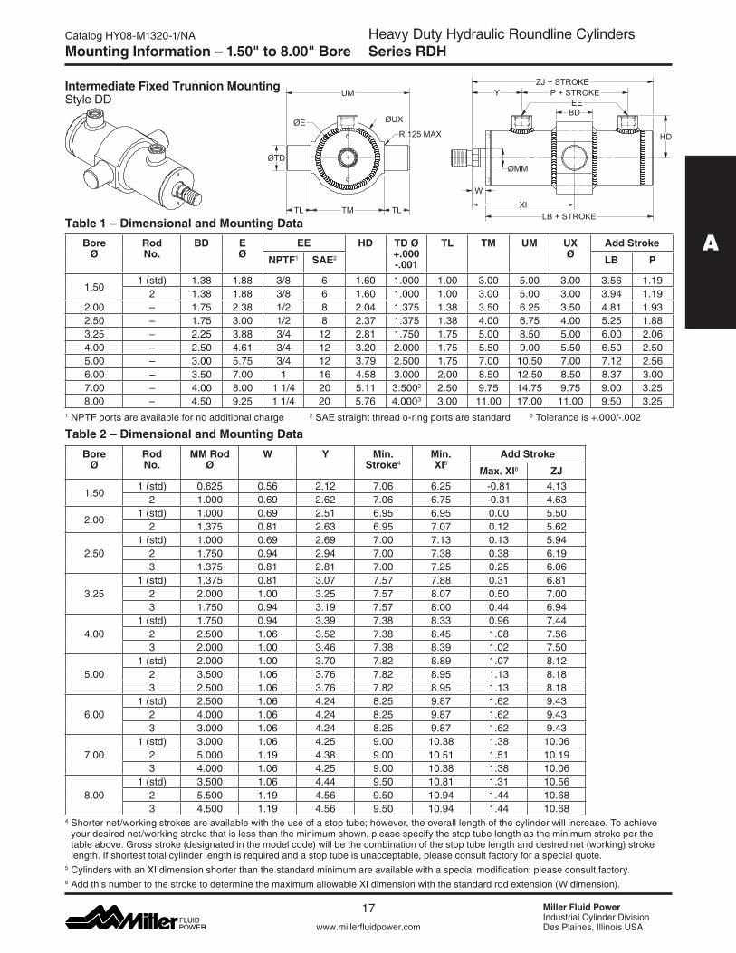
Mounting Information – 1.50" to 8.00" Bore
Intermediate Fixed Trunnion MountingStyle DD
W
ØE
ØTD
UM
TMTL TL
ØUX
P + STROKEZJ + STROKE
LB + STROKEXI
YEE
HD
BD
R.125 MAX
ØMM
1 NPTF ports are available for no additional charge 2 SAE straight thread o-ring ports are standard 3 Toleranceis+.000/-.002
Bore Ø
Rod No.
BD E Ø
EE HD TD Ø +.000 -.001
TL TM UM UX Ø
Add Stroke
NPTF1 SAE2 LB P
1.501 (std) 1.38 1.88 3/8 6 1.60 1.000 1.00 3.00 5.00 3.00 3.56 1.19
2 1.38 1.88 3/8 6 1.60 1.000 1.00 3.00 5.00 3.00 3.94 1.192.00 – 1.75 2.38 1/2 8 2.04 1.375 1.38 3.50 6.25 3.50 4.81 1.932.50 – 1.75 3.00 1/2 8 2.37 1.375 1.38 4.00 6.75 4.00 5.25 1.883.25 – 2.25 3.88 3/4 12 2.81 1.750 1.75 5.00 8.50 5.00 6.00 2.064.00 – 2.50 4.61 3/4 12 3.20 2.000 1.75 5.50 9.00 5.50 6.50 2.505.00 – 3.00 5.75 3/4 12 3.79 2.500 1.75 7.00 10.50 7.00 7.12 2.566.00 – 3.50 7.00 1 16 4.58 3.000 2.00 8.50 12.50 8.50 8.37 3.007.00 – 4.00 8.00 1 1/4 20 5.11 3.5003 2.50 9.75 14.75 9.75 9.00 3.258.00 – 4.50 9.25 1 1/4 20 5.76 4.0003 3.00 11.00 17.00 11.00 9.50 3.25
Table 1 – Dimensional and Mounting Data
Table 2 – Dimensional and Mounting Data
4 Shorter net/working strokes are available with the use of a stop tube; however, the overall length of the cylinder will increase. To achieve your desired net/working stroke that is less than the minimum shown, please specify the stop tube length as the minimum stroke per the tableabove.Grossstroke(designatedinthemodelcode)willbethecombinationofthestoptubelengthanddesirednet(working)strokelength. If shortest total cylinder length is required and a stop tube is unacceptable, please consult factory for a special quote.
5 Cylinders with an XI dimension shorter than the standard minimum are available with a special modification; please consult factory.6AddthisnumbertothestroketodeterminethemaximumallowableXIdimensionwiththestandardrodextension(Wdimension).
Bore Ø
Rod No.
MM Rod Ø
W Y Min. Stroke4
Min. XI5
Add Stroke
Max. XI6 ZJ
1.501 (std) 0.625 0.56 2.12 7.06 6.25 -0.81 4.13
2 1.000 0.69 2.62 7.06 6.75 -0.31 4.63
2.001 (std) 1.000 0.69 2.51 6.95 6.95 0.00 5.50
2 1.375 0.81 2.63 6.95 7.07 0.12 5.62
2.501 (std) 1.000 0.69 2.69 7.00 7.13 0.13 5.94
2 1.750 0.94 2.94 7.00 7.38 0.38 6.193 1.375 0.81 2.81 7.00 7.25 0.25 6.06
3.251 (std) 1.375 0.81 3.07 7.57 7.88 0.31 6.81
2 2.000 1.00 3.25 7.57 8.07 0.50 7.003 1.750 0.94 3.19 7.57 8.00 0.44 6.94
4.001 (std) 1.750 0.94 3.39 7.38 8.33 0.96 7.44
2 2.500 1.06 3.52 7.38 8.45 1.08 7.563 2.000 1.00 3.46 7.38 8.39 1.02 7.50
5.001 (std) 2.000 1.00 3.70 7.82 8.89 1.07 8.12
2 3.500 1.06 3.76 7.82 8.95 1.13 8.183 2.500 1.06 3.76 7.82 8.95 1.13 8.18
6.001 (std) 2.500 1.06 4.24 8.25 9.87 1.62 9.43
2 4.000 1.06 4.24 8.25 9.87 1.62 9.433 3.000 1.06 4.24 8.25 9.87 1.62 9.43
7.001 (std) 3.000 1.06 4.25 9.00 10.38 1.38 10.06
2 5.000 1.19 4.38 9.00 10.51 1.51 10.193 4.000 1.06 4.25 9.00 10.38 1.38 10.06
8.001 (std) 3.500 1.06 4.44 9.50 10.81 1.31 10.56
2 5.500 1.19 4.56 9.50 10.94 1.44 10.683 4.500 1.19 4.56 9.50 10.94 1.44 10.68
18
Heavy Duty Hydraulic Roundline CylindersSeries RDH
Miller Fluid PowerIndustrial Cylinder DivisionDes Plaines, Illinois USAwww.millerfluidpower.com
Catalog HY08-M1320-1/NAMounting Information – 1.50" to 8.00" Bore
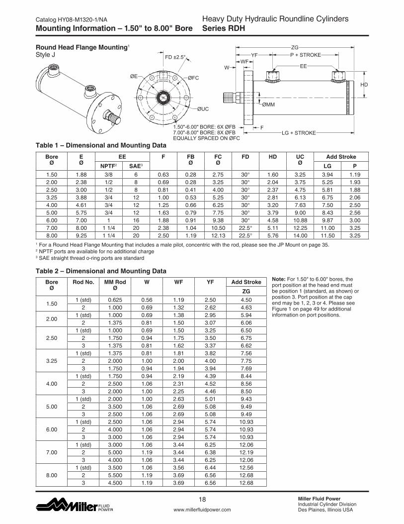
Round Head Flange Mounting1 Style J
Table 1 – Dimensional and Mounting Data
Table 2 – Dimensional and Mounting Data
ØFC
1.50"-6.00" BORE: 6X ØFB7.00"-8.00" BORE: 8X ØFBEQUALLY SPACED ON ØFC
ØUC
FLG + STROKE
P + STROKE
ØE
EE
HD
FD ±2.5°WF
W
YFZG
ØMM
1 For a Round Head Flange Mounting that includes a male pilot, concentric with the rod, please see the JP Mount on page 35. 2 NPTF ports are available for no additional charge 3 SAE straight thread o-ring ports are standard
Bore Ø
Rod No. MM Rod Ø
W WF YF Add Stroke
ZG
1.501 (std) 0.625 0.56 1.19 2.50 4.50
2 1.000 0.69 1.32 2.62 4.63
2.001 (std) 1.000 0.69 1.38 2.95 5.94
2 1.375 0.81 1.50 3.07 6.06
2.501 (std) 1.000 0.69 1.50 3.25 6.50
2 1.750 0.94 1.75 3.50 6.753 1.375 0.81 1.62 3.37 6.62
3.251 (std) 1.375 0.81 1.81 3.82 7.56
2 2.000 1.00 2.00 4.00 7.753 1.750 0.94 1.94 3.94 7.69
4.001 (std) 1.750 0.94 2.19 4.39 8.44
2 2.500 1.06 2.31 4.52 8.563 2.000 1.00 2.25 4.46 8.50
5.001 (std) 2.000 1.00 2.63 5.01 9.43
2 3.500 1.06 2.69 5.08 9.493 2.500 1.06 2.69 5.08 9.49
6.001 (std) 2.500 1.06 2.94 5.74 10.93
2 4.000 1.06 2.94 5.74 10.933 3.000 1.06 2.94 5.74 10.93
7.001 (std) 3.000 1.06 3.44 6.25 12.06
2 5.000 1.19 3.44 6.38 12.193 4.000 1.06 3.44 6.25 12.06
8.001 (std) 3.500 1.06 3.56 6.44 12.56
2 5.500 1.19 3.69 6.56 12.683 4.500 1.19 3.69 6.56 12.68
Bore Ø
E Ø
EE F FB Ø
FC Ø
FD HD UC Ø
Add Stroke
NPTF2 SAE3 LG P1.50 1.88 3/8 6 0.63 0.28 2.75 30° 1.60 3.25 3.94 1.192.00 2.38 1/2 8 0.69 0.28 3.25 30° 2.04 3.75 5.25 1.932.50 3.00 1/2 8 0.81 0.41 4.00 30° 2.37 4.75 5.81 1.883.25 3.88 3/4 12 1.00 0.53 5.25 30° 2.81 6.13 6.75 2.064.00 4.61 3/4 12 1.25 0.66 6.25 30° 3.20 7.63 7.50 2.505.00 5.75 3/4 12 1.63 0.79 7.75 30° 3.79 9.00 8.43 2.566.00 7.00 1 16 1.88 0.91 9.38 30° 4.58 10.88 9.87 3.007.00 8.00 1 1/4 20 2.38 1.04 10.50 22.5° 5.11 12.25 11.00 3.258.00 9.25 1 1/4 20 2.50 1.19 12.13 22.5° 5.76 14.00 11.50 3.25
Note:For1.50"to6.00"bores,the port position at the head end must be position 1 (standard, as shown) or position 3. Port position at the cap end may be 1, 2, 3 or 4. Please see Figure 1 on page 49 for additional information on port positions.
19
Heavy Duty Hydraulic Roundline CylindersSeries RDH
A
www.millerfluidpower.com
Catalog HY08-M1320-1/NA
Miller Fluid PowerIndustrial Cylinder DivisionDes Plaines, Illinois USA
Mounting Information – 1.50" to 8.00" Bore
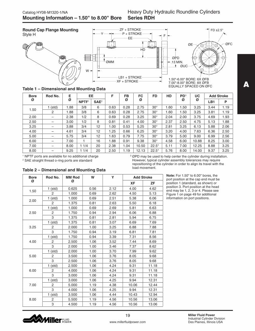
Round Cap Flange Mounting Style H
LB1 + STROKE
F
ZF + STROKE
XF + STROKE
Y P + STROKE
W
HD
EE
ØMMØPD
.13 MIN.
ØE
ØUC
ØFC
1.50"-6.00" BORE: 6X ØFB7.00"-8.00" BORE: 8X ØFBEQUALLY SPACED ON ØFC
FD ±2.5°
Table 1 – Dimensional and Mounting Data
Table 2 – Dimensional and Mounting Data
1 NPTF ports are available for no additional charge 2 SAE straight thread o-ring ports are standard
Bore Ø
Rod No. E Ø
EE F FB Ø
FC Ø
FD HD PD3 Ø
UC Ø
Add Stroke
NPTF1 SAE2 LB1 P
1.501 (std) 1.88 3/8 6 0.63 0.28 2.75 30° 1.60 1.50 3.25 3.44 1.19
2 1.88 3/8 6 0.63 0.28 2.75 30° 1.60 1.50 3.25 3.81 1.192.00 – 2.38 1/2 8 0.69 0.28 3.25 30° 2.04 2.00 3.75 4.69 1.932.50 – 3.00 1/2 8 0.81 0.41 4.00 30° 2.37 2.50 4.75 5.13 1.883.25 – 3.88 3/4 12 1.00 0.53 5.25 30° 2.81 3.25 6.13 5.88 2.064.00 – 4.61 3/4 12 1.25 0.66 6.25 30° 3.20 4.00 7.63 6.36 2.505.00 – 5.75 3/4 12 1.63 0.79 7.75 30° 3.79 5.00 9.00 6.99 2.566.00 – 7.00 1 16 1.88 0.91 9.38 30° 4.58 6.00 10.88 8.25 3.007.00 – 8.00 1 1/4 20 2.38 1.04 10.50 22.5° 5.11 7.00 12.25 8.88 3.258.00 – 9.25 1 1/4 20 2.50 1.19 12.13 22.5° 5.76 8.00 14.00 9.37 3.25
Bore Ø
Rod No. MM Rod Ø
W Y Add Stroke
XF ZF
1.501 (std) 0.625 0.56 2.12 4.00 4.62
2 1.000 0.69 2.62 4.50 5.13
2.001 (std) 1.000 0.69 2.51 5.38 6.06
2 1.375 0.81 2.63 5.50 6.18
2.501 (std) 1.000 0.69 2.69 5.81 6.63
2 1.750 0.94 2.94 6.06 6.883 1.375 0.81 2.81 5.94 6.75
3.251 (std) 1.375 0.81 3.07 6.69 7.69
2 2.000 1.00 3.25 6.88 7.883 1.750 0.94 3.19 6.81 7.81
4.001 (std) 1.750 0.94 3.39 7.31 8.56
2 2.500 1.06 3.52 7.44 8.693 2.000 1.00 3.46 7.37 8.62
5.001 (std) 2.000 1.00 3.70 7.99 9.62
2 3.500 1.06 3.76 8.05 9.683 2.500 1.06 3.76 8.05 9.68
6.001 (std) 2.500 1.06 4.24 9.31 11.18
2 4.000 1.06 4.24 9.31 11.183 3.000 1.06 4.24 9.31 11.18
7.001 (std) 3.000 1.06 4.25 9.94 12.31
2 5.000 1.19 4.38 10.06 12.443 4.000 1.06 4.25 9.94 12.31
8.001 (std) 3.500 1.06 4.44 10.43 12.94
2 5.500 1.19 4.56 10.56 13.063 4.500 1.19 4.56 10.56 13.06
3 ØPD may be used to help center the cylinder during installation. However, typical cylinder assembly tolerances may require repositioning of the cylinder in order to align its travel with the load movement.
Note:For1.50"to6.00"bores,theport position at the cap end must be position 1 (standard, as shown) or position 3. Port position at the head end may be 1, 2, 3 or 4. Please see Figure 1 on page 49 for additional information on port positions.
20
Heavy Duty Hydraulic Roundline CylindersSeries RDH
Miller Fluid PowerIndustrial Cylinder DivisionDes Plaines, Illinois USAwww.millerfluidpower.com
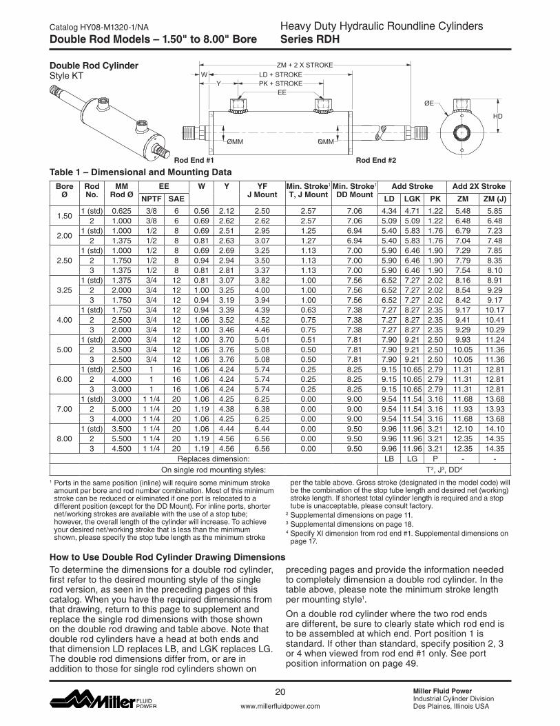
Catalog HY08-M1320-1/NADouble Rod Models – 1.50" to 8.00" Bore
To determine the dimensions for a double rod cylinder, first refer to the desired mounting style of the single rod version, as seen in the preceding pages of this catalog.Whenyouhavetherequireddimensionsfromthat drawing, return to this page to supplement and replace the single rod dimensions with those shown on the double rod drawing and table above. Note that double rod cylinders have a head at both ends and thatdimensionLDreplacesLB,andLGKreplacesLG. The double rod dimensions differ from, or are in addition to those for single rod cylinders shown on
preceding pages and provide the information needed to completely dimension a double rod cylinder. In the table above, please note the minimum stroke length per mounting style1.
On a double rod cylinder where the two rod ends are different, be sure to clearly state which rod end is to be assembled at which end. Port position 1 is standard. If other than standard, specify position 2, 3 or 4 when viewed from rod end #1 only. See port position information on page 49.
How to Use Double Rod Cylinder Drawing Dimensions
Rod End #1 Rod End #2
Double Rod CylinderStyle KT LD + STROKEW
PK + STROKEY
ZM + 2 X STROKE
EEØE
HD
ØMM MMØ
1 Ports in the same position (inline) will require some minimum stroke amount per bore and rod number combination. Most of this minimum stroke can be reduced or eliminated if one port is relocated to a different position (except for the DD Mount). For inline ports, shorter net/working strokes are available with the use of a stop tube; however, the overall length of the cylinder will increase. To achieve your desired net/working stroke that is less than the minimum shown, please specify the stop tube length as the minimum stroke
Bore Ø
Rod No.
MM Rod Ø
EE W Y YF J Mount
Min. Stroke1
T, J MountMin. Stroke1
DD MountAdd Stroke Add 2X Stroke
NPTF SAE LD LGK PK ZM ZM (J)
1.501 (std) 0.625 3/8 6 0.56 2.12 2.50 2.57 7.06 4.34 4.71 1.22 5.48 5.85
2 1.000 3/8 6 0.69 2.62 2.62 2.57 7.06 5.09 5.09 1.22 6.48 6.48
2.001 (std) 1.000 1/2 8 0.69 2.51 2.95 1.25 6.94 5.40 5.83 1.76 6.79 7.23
2 1.375 1/2 8 0.81 2.63 3.07 1.27 6.94 5.40 5.83 1.76 7.04 7.48
2.501 (std) 1.000 1/2 8 0.69 2.69 3.25 1.13 7.00 5.90 6.46 1.90 7.29 7.85
2 1.750 1/2 8 0.94 2.94 3.50 1.13 7.00 5.90 6.46 1.90 7.79 8.353 1.375 1/2 8 0.81 2.81 3.37 1.13 7.00 5.90 6.46 1.90 7.54 8.10
3.251 (std) 1.375 3/4 12 0.81 3.07 3.82 1.00 7.56 6.52 7.27 2.02 8.16 8.91
2 2.000 3/4 12 1.00 3.25 4.00 1.00 7.56 6.52 7.27 2.02 8.54 9.293 1.750 3/4 12 0.94 3.19 3.94 1.00 7.56 6.52 7.27 2.02 8.42 9.17
4.001 (std) 1.750 3/4 12 0.94 3.39 4.39 0.63 7.38 7.27 8.27 2.35 9.17 10.17
2 2.500 3/4 12 1.06 3.52 4.52 0.75 7.38 7.27 8.27 2.35 9.41 10.413 2.000 3/4 12 1.00 3.46 4.46 0.75 7.38 7.27 8.27 2.35 9.29 10.29
5.001 (std) 2.000 3/4 12 1.00 3.70 5.01 0.51 7.81 7.90 9.21 2.50 9.93 11.24
2 3.500 3/4 12 1.06 3.76 5.08 0.50 7.81 7.90 9.21 2.50 10.05 11.363 2.500 3/4 12 1.06 3.76 5.08 0.50 7.81 7.90 9.21 2.50 10.05 11.36
6.001 (std) 2.500 1 16 1.06 4.24 5.74 0.25 8.25 9.15 10.65 2.79 11.31 12.81
2 4.000 1 16 1.06 4.24 5.74 0.25 8.25 9.15 10.65 2.79 11.31 12.813 3.000 1 16 1.06 4.24 5.74 0.25 8.25 9.15 10.65 2.79 11.31 12.81
7.001 (std) 3.000 1 1/4 20 1.06 4.25 6.25 0.00 9.00 9.54 11.54 3.16 11.68 13.68
2 5.000 1 1/4 20 1.19 4.38 6.38 0.00 9.00 9.54 11.54 3.16 11.93 13.933 4.000 1 1/4 20 1.06 4.25 6.25 0.00 9.00 9.54 11.54 3.16 11.68 13.68
8.001 (std) 3.500 1 1/4 20 1.06 4.44 6.44 0.00 9.50 9.96 11.96 3.21 12.10 14.10
2 5.500 1 1/4 20 1.19 4.56 6.56 0.00 9.50 9.96 11.96 3.21 12.35 14.353 4.500 1 1/4 20 1.19 4.56 6.56 0.00 9.50 9.96 11.96 3.21 12.35 14.35
Replaces dimension: LB LG P - -On single rod mounting styles: T2, J3, DD4
perthetableabove.Grossstroke(designatedinthemodelcode)willbe the combination of the stop tube length and desired net (working) stroke length. If shortest total cylinder length is required and a stop tube is unacceptable, please consult factory.
2 Supplemental dimensions on page 11. 3 Supplemental dimensions on page 18. 4 Specify XI dimension from rod end #1. Supplemental dimensions on
page 17.
Table 1 – Dimensional and Mounting Data
21
B
Heavy Duty Hydraulic Roundline CylindersSeries RDH
www.millerfluidpower.com
Catalog HY08-M1320-1/NA
Miller Fluid PowerIndustrial Cylinder DivisionDes Plaines, Illinois USA
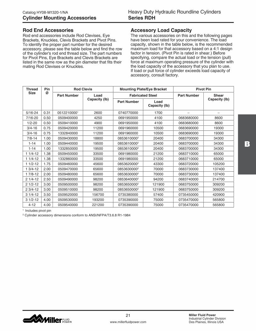
Rod End AccessoriesRod end accessories include Rod Clevises, Eye Brackets, Knuckles, Clevis Brackets and Pivot Pins. To identify the proper part number for the desired accessory, please see the table below and find the row ofthecylinder'srodendthreadsize.Thepartnumbersfor Pivot Pins, Eye Brackets and Clevis Brackets are listed in the same row as the pin diameter that fits their mating Rod Clevises or Knuckles.
Accessory Load CapacityThe various accessories on this and the following pages have been load rated for your convenience. The load capacity, shown in the table below, is the recommended maximum load for that accessory based on a 4:1 design factor in tension. (Pivot Pin is rated in shear.) Before specifying, compare the actual load or the tension (pull) force at maximum operating pressure of the cylinder with the load capacity of the accessory that you plan to use. If load or pull force of cylinder exceeds load capacity of accessory, consult factory.
Cylinder Mounting Accessories
1 Includes pivot pin 2 Cylinder accessory dimensions conform to ANSI/NFPA/T3.6.8 R1-1984
Thread Size
PinØ
Rod Clevis Mounting Plate/Eye Bracket Pivot Pin
Part Number Load Capacity (lb)
Fabricated Steel Part Number Shear Capacity (lb)
Part Number Load Capacity (lb)
5/16-24 0.31 05122100001 2600 0740770000 1700 – –7/16-20 0.50 0509400000 4250 0691950000 4100 0683680000 86001/2-20 0.50 0509410000 4900 0691950000 4100 0683680000 86003/4-16 0.75 0509420000 11200 0691960000 10500 0683690000 193003/4-16 0.75 1332840000 11200 0691960000 10500 0683690000 193007/8-14 1.00 0509430000 18800 08536100002 20400 0683700000 343001-14 1.00 0509440000 19500 08536100002 20400 0683700000 343001-14 1.00 1332850000 19500 08536100002 20400 0683700000 34300
1 1/4-12 1.38 0509450000 33500 0691980000 21200 0683710000 650001 1/4-12 1.38 1332860000 33500 0691980000 21200 0683710000 650001 1/2-12 1.75 0509460000 45600 08536200002 43300 0683720000 1052001 3/4-12 2.00 0509470000 65600 08536300002 70000 0683730000 1374001 7/8-12 2.00 0509480000 65600 08536300002 70000 0683730000 1374002 1/4-12 2.50 0509490000 98200 08536400002 94200 0683740000 2147002 1/2-12 3.00 0509500000 98200 08536500002 121900 0683750000 3092002 3/4-12 3.00 0509510000 98200 08536500002 121900 0683750000 3092003 1/4-12 3.50 0509520000 156700 0735380000 57400 0735450000 4209003 1/2-12 4.00 0509530000 193200 0735390000 75000 0735470000 565800
4-12 4.00 0509540000 221200 0735390000 75000 0735470000 565800

Heavy Duty Hydraulic Roundline CylindersSeries RDH
Miller Fluid PowerIndustrial Cylinder DivisionDes Plaines, Illinois USAwww.millerfluidpower.com
Catalog HY08-M1320-1/NA
22
Note:1. Pivot Pins are furnished with BB
Mount cylinders as standard.2. Pivot Pins are furnished with (2)
Retaining Rings (except as noted).
3. Pivot Pins must be ordered as a separate item if to be used with Knuckles, Rod Clevises, or Clevis Brackets.
4 WhenusedtomatewiththeRodClevis,selectbyPivotPindiameterinthetableonthepriorpage.
Fabricated Steel Mounting Plate/Eye Bracket Dimensions4
MR
LR
RE
F
M 25°
FL
CB
+ .004+ .002
RE
ØCDØDD(X4)
CBCW CWER
KK THREAD
+.004+.002ØCD
A
CE
Rod Clevis Dimensions
Pivot Pin DimensionsCL
ØCD+.001-.002
1 Includes Pivot Pin2 Consult appropriate cylinder rod end dimensions for compatibility.
3This size supplied with cotter pins.
Cylinder Mounting Accessories
Part Number Pin Ø
A CB CD Ø
CE CW ER KK Thread
05122100001 0.31 0.81 0.34 0.313 2.25 0.20 0.30 5/16-240509400000 0.50 0.75 0.77 0.500 1.50 0.49 0.50 7/16-200509410000 0.50 0.75 0.77 0.500 1.50 0.49 0.50 1/2-200509420000 0.75 1.13 1.27 0.750 2.13 0.62 0.75 3/4-161332840000 0.75 1.13 1.27 0.750 2.38 0.62 0.75 3/4-160509430000 1.00 1.63 1.52 1.000 2.94 0.74 1.00 7/8-140509440000 1.00 1.63 1.52 1.000 2.94 0.74 1.00 1-141332850000 1.00 1.63 1.52 1.000 3.13 0.74 1.00 1-140509450000 1.38 1.88 2.04 1.375 3.75 0.99 1.38 1 1/4-121332860000 1.38 2.00 2.04 1.375 4.13 0.99 1.38 1 1/4-120509460000 1.75 2.25 2.54 1.750 4.50 1.24 1.75 1 1/2-120509470000 2.00 3.00 2.54 2.000 5.50 1.24 2.00 1 3/4-120509480000 2.00 3.00 2.54 2.000 5.50 1.24 2.00 1 7/8-120509490000 2.50 3.50 3.04 2.500 6.50 1.49 2.50 2 1/4-120509500000 3.00 3.50 3.04 3.000 6.75 1.49 2.75 2 1/2-120509510000 3.00 3.50 3.04 3.000 6.75 1.49 2.75 2 3/4-120509520000 3.50 3.502 4.04 3.500 7.75 1.98 3.50 3 1/4-120509530000 4.00 4.002 4.54 4.000 8.81 2.23 4.00 3 1/2-120509540000 4.00 4.002 4.54 4.000 8.81 2.23 4.00 4-12
Part Number CD Ø CL
0683680000 0.500 1.88
0683690000 0.750 2.63
0683700000 1.000 3.13
0683710000 1.375 4.13
0683720000 1.750 5.19
0683730000 2.000 5.19
0683740000 2.500 6.19
0683750000 3.000 6.25
0735450000 3.500 8.25
07354700003 4.000 9.00
Fabricated Steel
Part Number
Pin Ø
CB CD Ø
DD Ø
E F FL LR M MR R For Use With BB Mount Per Bore:
0740770000 0.31 0.31 0.313 0.27 2.25 0.38 1.00 0.63 0.38 0.50 1.75 -0691950000 0.50 0.75 0.500 0.41 2.50 0.38 1.13 0.75 0.50 0.56 1.63 1.50069196000M 0.75 1.06 0.750 0.53 3.50 0.63 1.88 1.25 0.75 0.88 2.55 2.000691960000 0.75 1.25 0.750 0.53 3.50 0.63 1.88 1.25 0.75 0.88 2.55 2.500853610000 1.00 1.50 1.000 0.66 4.50 0.88 2.38 1.50 1.00 1.25 3.25 3.250691980000 1.38 2.00 1.375 0.66 5.00 0.88 3.00 2.13 1.38 1.63 3.82 4.000853620000 1.75 2.50 1.750 0.91 6.50 1.13 3.38 2.25 1.75 2.13 4.95 5.000853630000 2.00 2.50 2.000 1.06 7.50 1.50 4.00 2.50 2.00 2.44 5.73 6.000853640000 2.50 3.00 2.500 1.19 8.50 1.75 4.75 3.00 2.50 3.00 6.58 7.000853650000 3.00 3.00 3.000 1.31 9.50 2.00 5.25 3.25 2.75 3.25 7.50 8.000735380000 3.50 4.00 3.500 1.81 12.63 1.69 5.69 4.00 3.50 4.13 9.62 -0735390000 4.00 4.50 4.000 2.06 14.88 1.94 6.44 4.50 4.00 5.25 11.45 -

23
B
Heavy Duty Hydraulic Roundline CylindersSeries RDH
www.millerfluidpower.com
Catalog HY08-M1320-1/NA
Miller Fluid PowerIndustrial Cylinder DivisionDes Plaines, Illinois USA
Accessory Load CapacityThe various accessories have been load rated for your convenience. The load capacity, shown in the table below, is the recommended maximum load for that accessory based on a 4:1 design factor in tension. (Pivot Pin is rated in shear.) Before specifying, compare the actual load or the tension (pull) force at the maxi-mum operating pressure of the cylinder with the load capacity of the accessory you plan to use. If load or pull force of cylinder exceeds load capacity of accessory, consult factory.
1This size supplied with cotter pins.
Cylinder Mounting Accessories
Rod End AccessoriesRod end accessories include Rod Clevises, Eye Brackets, Knuckles, Clevis Brackets and Pivot Pins. To identify the proper part number for the desired accessory, please see the table below and find the row ofthecylinder'srodendthreadsize.Thepartnumbersfor Pivot Pins, Eye Brackets and Clevis Brackets are listed in the same row as the pin diameter that fits their mating Rod Clevises or Knuckles.
Thread Size
Pin Ø Knuckle Clevis Bracket Pivot Pin
Part Number Load Capacity (lb)
Fabricated Steel Part Number Shear Capacity (lb)
Part Number Load Capacity (lb)
5/16-24 0.44 0740750000 3300 0740760000 3600 0740780000 66007/16-20 0.50 0690890000 5000 0692050000 7300 0683680000 86001/2-20 0.50 0690900000 5700 0692050000 7300 0683680000 86003/4-16 0.75 0690910000 12100 0692060000 10880 0683690000 193007/8-14 1.00 0690920000 13000 0692070000 15180 0683700000 343001-14 1.00 0690930000 21700 0692070000 15180 0683700000 34300
1 1/4-12 1.38 0690940000 33500 0692080000 23560 0683710000 650001 1/2-12 1.75 0690950000 45000 0692090000 21520 0683720000 1052001 3/4-12 2.00 0690960000 53500 0692100000 26000 0692150000 1374001 7/8-12 2.00 0690970000 75000 0692100000 26000 0692150000 1374002 1/4-12 2.50 0690980000 98700 0692110000 28710 0683740000 2147002 1/2-12 3.00 0690990000 110000 0692120000 28190 0683750000 3092002 3/4-12 3.00 0691000000 123300 0692130000 31390 0692160000 3092003 1/4-12 3.50 0735360000 161300 0735420000 80250 0735450000 4209003 1/2-12 3.50 0734370000 217300 0735420000 80250 0735450000 420900
4-12 4.00 0734380000 273800 0735430000 98420 0821810000 5658004 1/2-12 4.00 0734390000 308500 0735440000 108400 07354700001 565800
Heavy Duty Hydraulic Roundline CylindersSeries RDH
Miller Fluid PowerIndustrial Cylinder DivisionDes Plaines, Illinois USAwww.millerfluidpower.com
Catalog HY08-M1320-1/NA
24
Cylinder Mounting Accessories
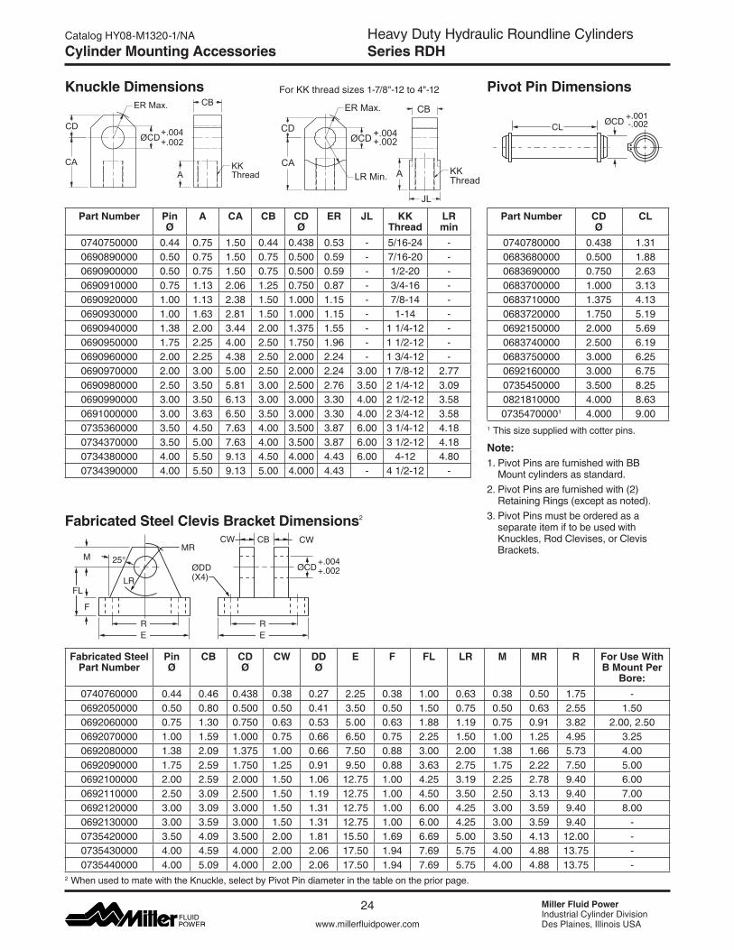
Knuckle Dimensions Pivot Pin Dimensions
CLØCD
+.001-.002
Fabricated Steel Clevis Bracket Dimensions2
25°MR
LR
RE
ØDD(X4)
F
M
FL
CW CWCB
+.004+.002
RE
ØCD
2 WhenusedtomatewiththeKnuckle,selectbyPivotPindiameterinthetableonthepriorpage.
Note: 1. Pivot Pins are furnished with BB
Mount cylinders as standard.2. Pivot Pins are furnished with (2)
Retaining Rings (except as noted).3. Pivot Pins must be ordered as a
separate item if to be used with Knuckles, Rod Clevises, or Clevis Brackets.
1 This size supplied with cotter pins.
Part Number Pin Ø
A CA CB CD Ø
ER JL KK Thread
LR min
0740750000 0.44 0.75 1.50 0.44 0.438 0.53 - 5/16-24 -0690890000 0.50 0.75 1.50 0.75 0.500 0.59 - 7/16-20 -0690900000 0.50 0.75 1.50 0.75 0.500 0.59 - 1/2-20 -0690910000 0.75 1.13 2.06 1.25 0.750 0.87 - 3/4-16 -0690920000 1.00 1.13 2.38 1.50 1.000 1.15 - 7/8-14 -0690930000 1.00 1.63 2.81 1.50 1.000 1.15 - 1-14 -0690940000 1.38 2.00 3.44 2.00 1.375 1.55 - 1 1/4-12 -0690950000 1.75 2.25 4.00 2.50 1.750 1.96 - 1 1/2-12 -0690960000 2.00 2.25 4.38 2.50 2.000 2.24 - 1 3/4-12 -0690970000 2.00 3.00 5.00 2.50 2.000 2.24 3.00 1 7/8-12 2.770690980000 2.50 3.50 5.81 3.00 2.500 2.76 3.50 2 1/4-12 3.090690990000 3.00 3.50 6.13 3.00 3.000 3.30 4.00 2 1/2-12 3.580691000000 3.00 3.63 6.50 3.50 3.000 3.30 4.00 2 3/4-12 3.580735360000 3.50 4.50 7.63 4.00 3.500 3.87 6.00 3 1/4-12 4.180734370000 3.50 5.00 7.63 4.00 3.500 3.87 6.00 3 1/2-12 4.180734380000 4.00 5.50 9.13 4.50 4.000 4.43 6.00 4-12 4.800734390000 4.00 5.50 9.13 5.00 4.000 4.43 - 4 1/2-12 -
Part Number CD Ø
CL
0740780000 0.438 1.310683680000 0.500 1.880683690000 0.750 2.630683700000 1.000 3.130683710000 1.375 4.130683720000 1.750 5.190692150000 2.000 5.690683740000 2.500 6.190683750000 3.000 6.250692160000 3.000 6.750735450000 3.500 8.250821810000 4.000 8.6307354700001 4.000 9.00
Fabricated Steel Part Number
Pin Ø
CB CD Ø
CW DD Ø
E F FL LR M MR R For Use With B Mount Per
Bore:0740760000 0.44 0.46 0.438 0.38 0.27 2.25 0.38 1.00 0.63 0.38 0.50 1.75 -0692050000 0.50 0.80 0.500 0.50 0.41 3.50 0.50 1.50 0.75 0.50 0.63 2.55 1.500692060000 0.75 1.30 0.750 0.63 0.53 5.00 0.63 1.88 1.19 0.75 0.91 3.82 2.00, 2.500692070000 1.00 1.59 1.000 0.75 0.66 6.50 0.75 2.25 1.50 1.00 1.25 4.95 3.250692080000 1.38 2.09 1.375 1.00 0.66 7.50 0.88 3.00 2.00 1.38 1.66 5.73 4.000692090000 1.75 2.59 1.750 1.25 0.91 9.50 0.88 3.63 2.75 1.75 2.22 7.50 5.000692100000 2.00 2.59 2.000 1.50 1.06 12.75 1.00 4.25 3.19 2.25 2.78 9.40 6.000692110000 2.50 3.09 2.500 1.50 1.19 12.75 1.00 4.50 3.50 2.50 3.13 9.40 7.000692120000 3.00 3.09 3.000 1.50 1.31 12.75 1.00 6.00 4.25 3.00 3.59 9.40 8.000692130000 3.00 3.59 3.000 1.50 1.31 12.75 1.00 6.00 4.25 3.00 3.59 9.40 -0735420000 3.50 4.09 3.500 2.00 1.81 15.50 1.69 6.69 5.00 3.50 4.13 12.00 -0735430000 4.00 4.59 4.000 2.00 2.06 17.50 1.94 7.69 5.75 4.00 4.88 13.75 -0735440000 4.00 5.09 4.000 2.00 2.06 17.50 1.94 7.69 5.75 4.00 4.88 13.75 -
+.004+.002
CB
CA
CD
ER Max.
AKKThread
ØCD +.004+.002
CD
CALR Min.
ØCD
ER Max.
JL
A KKThread
CB
ForKKthreadsizes1-7/8"-12to4"-12
25
B
Heavy Duty Hydraulic Roundline CylindersSeries RDH
www.millerfluidpower.com
Catalog HY08-M1320-1/NA
Miller Fluid PowerIndustrial Cylinder DivisionDes Plaines, Illinois USA
Notes
Notes
Heavy Duty Hydraulic Roundline CylindersSeries RDH
Miller Fluid PowerIndustrial Cylinder DivisionDes Plaines, Illinois USAwww.millerfluidpower.com
Catalog HY08-M1320-1/NA
26
Spherical Bearing Mount Accessories
LE
ØCD
JKTHD
ER (MAX)
LUBEFITTINGCE
A
EX
ØJL
Pivot Pin (Inch Sizes)
Pivot Pins are furnished with (2) Retainer Rings.
Accessories for spherical bearing mount cylinders include Spherical Rod Eyes, Pivot Pins and Clevis
Brackets. To identify the proper part number for the desired accessory, please see the tables below.
Spherical Rod Eye (Inch Sizes)
MR
LR
RE
Ø DD(X4)
F
M
FL
CW CWCF
+.004+.002
RE
ØCD
CL
ØCD
Clevis Bracket for SB Mount Cap or Spherical Rod Eye (Inch Sizes)
Bore Ø
Part No. A CD Ø +.0000 -.0005
CE ER EX JK Thread
Size
JL Ø
LE Load Capacity (lb)
1.50 1322900000 0.69 0.5000 0.88 0.84 0.44 7/16-20 0.88 0.78 26442.00
1322910000 1.00 0.7500 1.25 1.19 0.66 3/4-16 1.31 1.06 94412.503.25 1322920000 1.50 1.0000 1.88 1.28 0.88 1-14 1.50 1.44 168604.00 1322930000 2.00 1.3750 2.13 1.72 1.19 1 1/4-12 2.00 1.51 285625.00 1322940000 2.13 1.7500 2.50 2.09 1.53 1 1/2-12 2.25 2.16 430056.00 1322950000 2.88 2.0000 2.75 2.53 1.75 1 7/8-12 2.75 2.50 70193
Bore Ø
Part No. CD Ø
CL Shear Capacity (lb)
1.50 0839620000 .4997 -.0004 1.56 86002.00
0839630000 .7497 -.0005 2.03 193002.503.25 0839640000 .9997 -.0005 2.50 343004.00 0839650000 1.3746 -.0006 3.31 650005.00 0839660000 1.7496 -.0006 4.22 1052006.00 0839670000 1.9996 -.0007 4.94 137400
Note:Standardsphericalbearingismaintenance-free(sealed)forCDØ>0.5000"
Part No.
A max
AX min
CH CN EF max
EN EU KK LF min
MA max Nm
N max
P Load Cap. (lb)
1452540000 40 15 42 12 -0.008 20 10 -.012 8 M10x1.25 16 10 17 M6 17981452550000 45 17 48 16 -0.008 22.5 14 -.012 11 M12x1.25 20 10 21 M6 28101452560000 55 19 58 20 -0.012 27.5 16 -.012 13 M14x1.5 25 25 25 M8 44961452570000 62 23 68 25 -0.012 32.5 20 -.012 17 M16x1.5 30 25 30 M8 71941452580000 80 29 85 30 -0.012 40 22 -.012 19 M20x1.5 35 45 36 M10 112401452590000 90 37 105 40 -0.012 50 28 -.012 23 M27x2 45 45 45 M10 179851452600000 105 46 130 50 -0.012 62.5 35 -.012 30 M33x2 58 80 55 M12 281011452610000 134 57 150 60 -0.015 80 44 -.015 38 M42x2 68 160 68 M16 449621452620000 156 64 185 80 -0.015 102.5 55 -.015 47 M48x2 92 310 90 M20 719391452630000 190 86 240 100 -0.020 120 70 -.020 57 M64x3 116 530 110 M24 112404
CH
LF
EF
P MA Torque
3°
EU
EN
AX
A
N
KK
CN3°
Spherical Rod Eye (Metric Sizes)
Note: Standard spherical bearing is maintenance-free (sealed)
BoreØ
Fabricated Steel Part Number
CDØ
CF CW DDØ
E F FL LR M MR R Load Capacity (lb)
1.50 0839470000 0.500 0.45 0.50 0.41 3.00 0.50 1.50 0.94 0.50 0.63 2.05 57702.00
0839480000 0.750 0.67 0.63 0.53 3.75 0.63 2.00 1.38 0.88 1.00 2.76 94502.503.25 0839490000 1.000 0.89 0.75 0.53 5.50 0.75 2.50 1.69 1.00 1.19 4.10 143004.00 0839500000 1.375 1.20 1.00 0.66 6.50 0.88 3.50 2.44 1.38 1.63 4.95 203225.00 0839510000 1.750 1.55 1.25 0.91 8.50 1.25 4.50 2.88 1.75 2.06 6.58 378006.00 0839520000 2.000 1.77 1.50 0.91 10.63 1.50 5.00 3.31 2.00 2.38 7.92 50375
Fabricated Steel
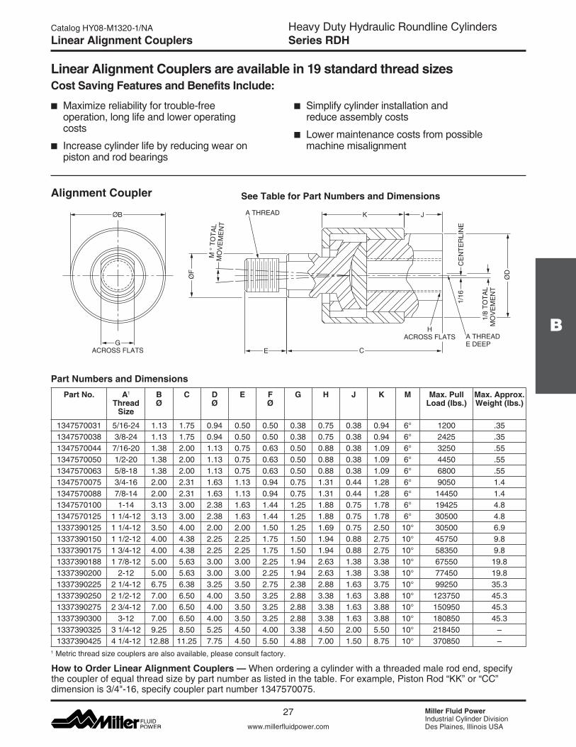
27
B
Heavy Duty Hydraulic Roundline CylindersSeries RDH
www.millerfluidpower.com
Catalog HY08-M1320-1/NA
Miller Fluid PowerIndustrial Cylinder DivisionDes Plaines, Illinois USA
Part No.
A max
AX min
CH CN EF max
EN EU KK LF min
MA max Nm
N max
P Load Cap. (lb)
1452540000 40 15 42 12 -0.008 20 10 -.012 8 M10x1.25 16 10 17 M6 17981452550000 45 17 48 16 -0.008 22.5 14 -.012 11 M12x1.25 20 10 21 M6 28101452560000 55 19 58 20 -0.012 27.5 16 -.012 13 M14x1.5 25 25 25 M8 44961452570000 62 23 68 25 -0.012 32.5 20 -.012 17 M16x1.5 30 25 30 M8 71941452580000 80 29 85 30 -0.012 40 22 -.012 19 M20x1.5 35 45 36 M10 112401452590000 90 37 105 40 -0.012 50 28 -.012 23 M27x2 45 45 45 M10 179851452600000 105 46 130 50 -0.012 62.5 35 -.012 30 M33x2 58 80 55 M12 281011452610000 134 57 150 60 -0.015 80 44 -.015 38 M42x2 68 160 68 M16 449621452620000 156 64 185 80 -0.015 102.5 55 -.015 47 M48x2 92 310 90 M20 719391452630000 190 86 240 100 -0.020 120 70 -.020 57 M64x3 116 530 110 M24 112404
Linear Alignment Couplers
Linear Alignment Couplers are available in 19 standard thread sizesCost Saving Features and Benefits Include:
n Simplify cylinder installation and reduce assembly costs
n Lower maintenance costs from possible machine misalignment
Alignment Coupler See Table for Part Numbers and Dimensions
ØD
1/16
CE
NTE
RLI
NE
A THREADE DEEP
K
CE
ØF
M °
TO
TAL
MO
VE
ME
NT
A THREADØB
GACROSS FLATS
J
1/8
TOTA
LM
OV
EM
EN
T
HACROSS FLATS
How to Order Linear Alignment Couplers — Whenorderingacylinderwithathreadedmalerodend,specifythe coupler of equal thread size by part number as listed in the table. For example, Piston Rod “KK” or “CC” dimensionis3/4"-16,specifycouplerpartnumber1347570075.
n Maximize reliability for trouble-free operation, long life and lower operating costs
n Increase cylinder life by reducing wear on piston and rod bearings
Part Numbers and DimensionsPart No. A1
Thread Size
B Ø
C D Ø
E F Ø
G H J K M Max. Pull Load (lbs.)
Max. Approx. Weight (lbs.)
1347570031 5/16-24 1.13 1.75 0.94 0.50 0.50 0.38 0.75 0.38 0.94 6° 1200 .351347570038 3/8-24 1.13 1.75 0.94 0.50 0.50 0.38 0.75 0.38 0.94 6° 2425 .351347570044 7/16-20 1.38 2.00 1.13 0.75 0.63 0.50 0.88 0.38 1.09 6° 3250 .551347570050 1/2-20 1.38 2.00 1.13 0.75 0.63 0.50 0.88 0.38 1.09 6° 4450 .551347570063 5/8-18 1.38 2.00 1.13 0.75 0.63 0.50 0.88 0.38 1.09 6° 6800 .551347570075 3/4-16 2.00 2.31 1.63 1.13 0.94 0.75 1.31 0.44 1.28 6° 9050 1.41347570088 7/8-14 2.00 2.31 1.63 1.13 0.94 0.75 1.31 0.44 1.28 6° 14450 1.41347570100 1-14 3.13 3.00 2.38 1.63 1.44 1.25 1.88 0.75 1.78 6° 19425 4.81347570125 1 1/4-12 3.13 3.00 2.38 1.63 1.44 1.25 1.88 0.75 1.78 6° 30500 4.81337390125 1 1/4-12 3.50 4.00 2.00 2.00 1.50 1.25 1.69 0.75 2.50 10° 30500 6.91337390150 1 1/2-12 4.00 4.38 2.25 2.25 1.75 1.50 1.94 0.88 2.75 10° 45750 9.81337390175 1 3/4-12 4.00 4.38 2.25 2.25 1.75 1.50 1.94 0.88 2.75 10° 58350 9.81337390188 1 7/8-12 5.00 5.63 3.00 3.00 2.25 1.94 2.63 1.38 3.38 10° 67550 19.81337390200 2-12 5.00 5.63 3.00 3.00 2.25 1.94 2.63 1.38 3.38 10° 77450 19.81337390225 2 1/4-12 6.75 6.38 3.25 3.50 2.75 2.38 2.88 1.63 3.75 10° 99250 35.31337390250 2 1/2-12 7.00 6.50 4.00 3.50 3.25 2.88 3.38 1.63 3.88 10° 123750 45.31337390275 2 3/4-12 7.00 6.50 4.00 3.50 3.25 2.88 3.38 1.63 3.88 10° 150950 45.31337390300 3-12 7.00 6.50 4.00 3.50 3.25 2.88 3.38 1.63 3.88 10° 180850 45.31337390325 3 1/4-12 9.25 8.50 5.25 4.50 4.00 3.38 4.50 2.00 5.50 10° 218450 –1337390425 4 1/4-12 12.88 11.25 7.75 4.50 5.50 4.88 7.00 1.50 8.75 10° 370850 –
1 Metric thread size couplers are also available, please consult factory.
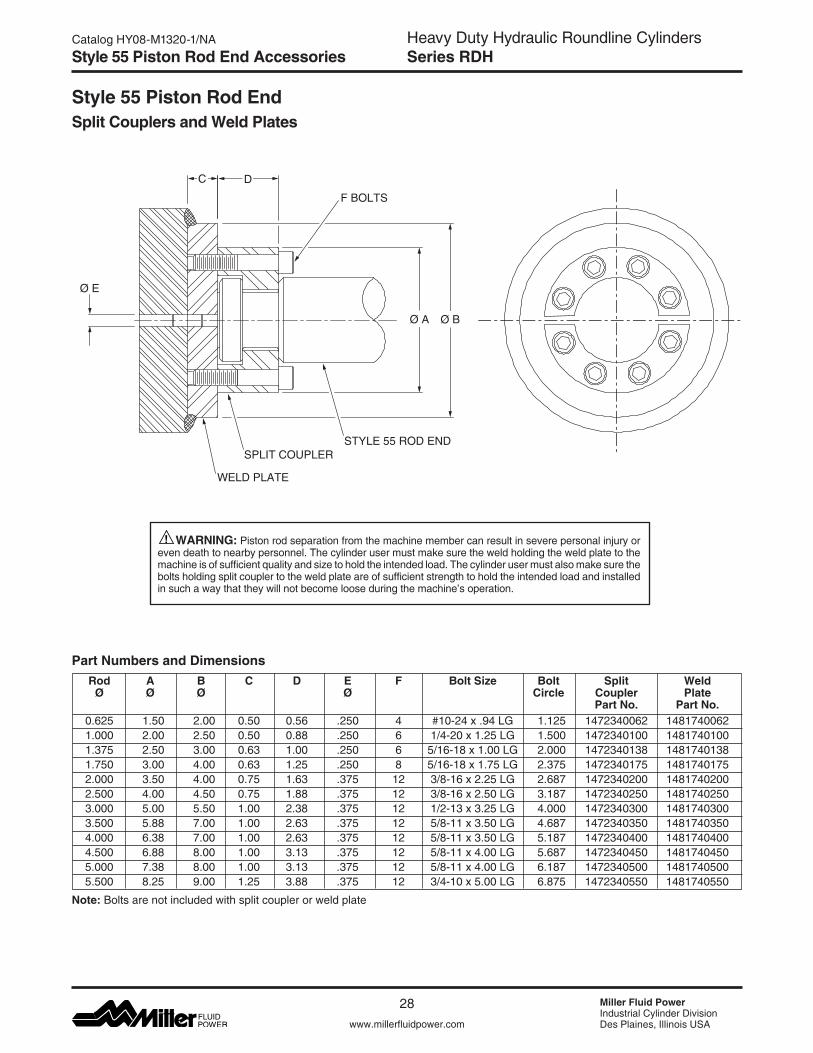
Heavy Duty Hydraulic Roundline CylindersSeries RDH
Miller Fluid PowerIndustrial Cylinder DivisionDes Plaines, Illinois USAwww.millerfluidpower.com
Catalog HY08-M1320-1/NA
28
Style 55 Piston Rod End Accessories
Rod A B C D E F Bolt Size Bolt Split Weld Ø Ø Ø Ø Circle Coupler Plate Part No. Part No. 0.625 1.50 2.00 0.50 0.56 .250 4 #10-24x.94LG 1.125 1472340062 1481740062 1.000 2.00 2.50 0.50 0.88 .250 6 1/4-20x1.25LG 1.500 1472340100 1481740100 1.375 2.50 3.00 0.63 1.00 .250 6 5/16-18x1.00LG 2.000 1472340138 1481740138 1.750 3.00 4.00 0.63 1.25 .250 8 5/16-18x1.75LG 2.375 1472340175 1481740175 2.000 3.50 4.00 0.75 1.63 .375 12 3/8-16x2.25LG 2.687 1472340200 1481740200 2.500 4.00 4.50 0.75 1.88 .375 12 3/8-16x2.50LG 3.187 1472340250 1481740250 3.000 5.00 5.50 1.00 2.38 .375 12 1/2-13x3.25LG 4.000 1472340300 1481740300 3.500 5.88 7.00 1.00 2.63 .375 12 5/8-11x3.50LG 4.687 1472340350 1481740350 4.000 6.38 7.00 1.00 2.63 .375 12 5/8-11x3.50LG 5.187 1472340400 1481740400 4.500 6.88 8.00 1.00 3.13 .375 12 5/8-11x4.00LG 5.687 1472340450 1481740450 5.000 7.38 8.00 1.00 3.13 .375 12 5/8-11x4.00LG 6.187 1472340500 1481740500 5.500 8.25 9.00 1.25 3.88 .375 12 3/4-10x5.00LG 6.875 1472340550 1481740550
Ø E
F BOLTS
STYLE 55 ROD ENDSPLIT COUPLER
WELD PLATE
DC
Ø BØ A
Part Numbers and Dimensions
Note: Bolts are not included with split coupler or weld plate
Style 55 Piston Rod EndSplit Couplers and Weld Plates
WARNING: Piston rod separation from the machine member can result in severe personal injury or even death to nearby personnel. The cylinder user must make sure the weld holding the weld plate to the machine is of sufficient quality and size to hold the intended load. The cylinder user must also make sure the bolts holding split coupler to the weld plate are of sufficient strength to hold the intended load and installed in such a way that they will not become loose during the machine’s operation.
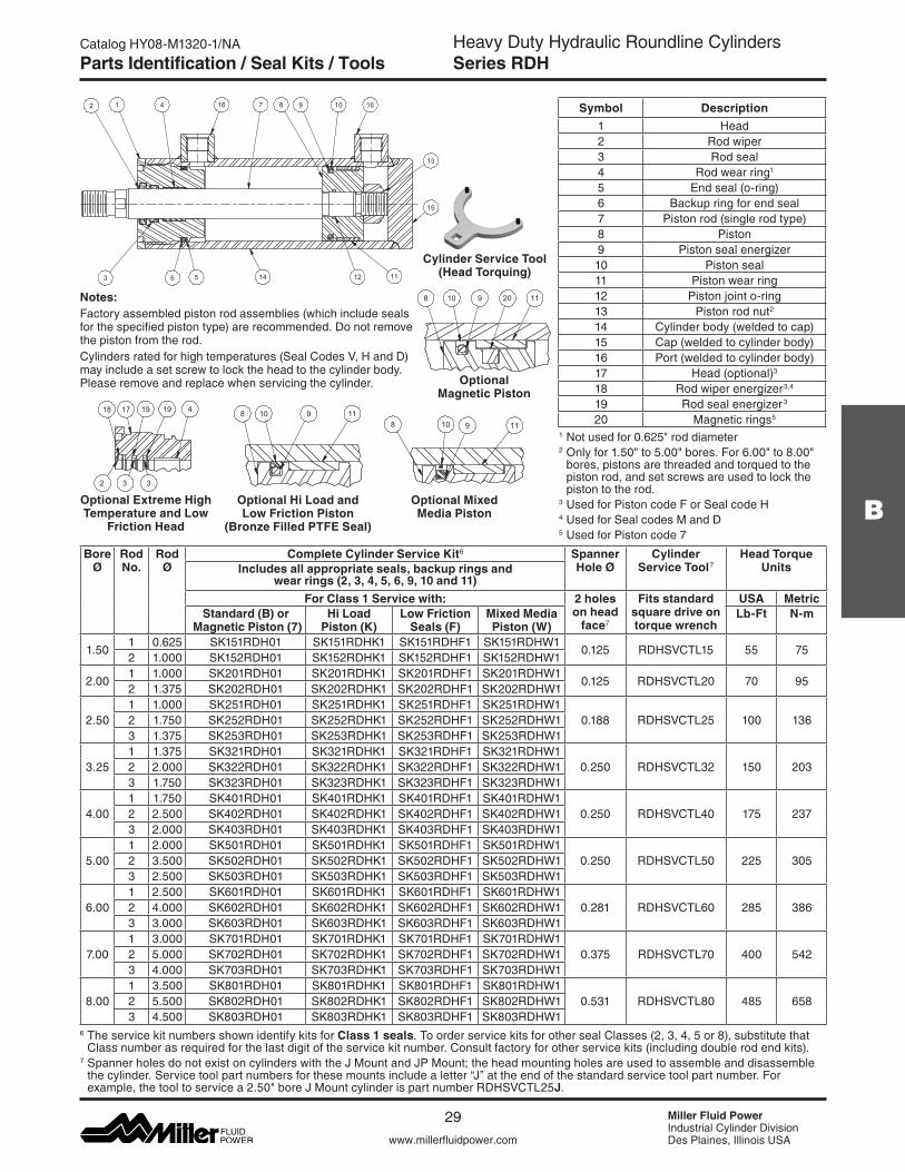
29
B
Heavy Duty Hydraulic Roundline CylindersSeries RDH
www.millerfluidpower.com
Catalog HY08-M1320-1/NA
Miller Fluid PowerIndustrial Cylinder DivisionDes Plaines, Illinois USA
Notes:Factory assembled piston rod assemblies (which include seals for the specified piston type) are recommended. Do not remove the piston from the rod.Cylindersratedforhightemperatures(SealCodesV,HandD) may include a set screw to lock the head to the cylinder body. Please remove and replace when servicing the cylinder.
Parts Identification / Seal Kits / Tools
10
11
4 987
1214
2
563
13
1 16 16
15
18 19 19 417
3 32
Symbol Description1 Head2 Rod wiper3 Rod seal4 Rod wear ring1
5 End seal (o-ring)6 Backup ring for end seal7 Piston rod (single rod type)8 Piston9 Piston seal energizer10 Piston seal11 Piston wear ring 12 Piston joint o-ring13 Piston rod nut2
14 Cylinder body (welded to cap)15 Cap (welded to cylinder body)16 Port (welded to cylinder body)17 Head (optional)3
18 Rod wiper energizer3,4
19 Rod seal energizer3
20 Magnetic rings5
6 The service kit numbers shown identify kits for Class 1 seals. To order service kits for other seal Classes (2, 3, 4, 5 or 8), substitute that Class number as required for the last digit of the service kit number. Consult factory for other service kits (including double rod end kits).
7 Spanner holes do not exist on cylinders with the J Mount and JP Mount; the head mounting holes are used to assemble and disassemble the cylinder. Service tool part numbers for these mounts include a letter “J” at the end of the standard service tool part number. For example,thetooltoservicea2.50"boreJMountcylinderispartnumberRDHSVCTL25J.
Cylinder Service Tool (Head Torquing)
Optional Mixed Media Piston
Optional Extreme High Temperature and Low
Friction Head
8 11910
Optional Magnetic Piston
Optional Hi Load and Low Friction Piston
(Bronze Filled PTFE Seal)
8 910 11
108 119 20
1 Not used for 0.625"roddiameter2 Onlyfor1.50"to5.00"bores.For6.00"to8.00"
bores, pistons are threaded and torqued to the piston rod, and set screws are used to lock the piston to the rod.
3 Used for Piston code F or Seal code H 4 Used for Seal codes M and D 5 Used for Piston code 7
Bore Ø
Rod No.
Rod Ø
Complete Cylinder Service Kit6 Spanner Hole Ø
Cylinder Service Tool7
Head Torque UnitsIncludes all appropriate seals, backup rings and
wear rings (2, 3, 4, 5, 6, 9, 10 and 11)For Class 1 Service with: 2 holes
on head face7
Fits standard square drive on torque wrench
USA MetricStandard (B) or
Magnetic Piston (7)Hi Load
Piston (K)Low Friction
Seals (F)Mixed Media Piston (W)
Lb-Ft N-m
1.501 0.625 SK151RDH01 SK151RDHK1 SK151RDHF1 SK151RDHW1
0.125 RDHSVCTL15 55 752 1.000 SK152RDH01 SK152RDHK1 SK152RDHF1 SK152RDHW1
2.001 1.000 SK201RDH01 SK201RDHK1 SK201RDHF1 SK201RDHW1
0.125 RDHSVCTL20 70 952 1.375 SK202RDH01 SK202RDHK1 SK202RDHF1 SK202RDHW1
2.501 1.000 SK251RDH01 SK251RDHK1 SK251RDHF1 SK251RDHW1
0.188 RDHSVCTL25 100 1362 1.750 SK252RDH01 SK252RDHK1 SK252RDHF1 SK252RDHW13 1.375 SK253RDH01 SK253RDHK1 SK253RDHF1 SK253RDHW1
3.251 1.375 SK321RDH01 SK321RDHK1 SK321RDHF1 SK321RDHW1
0.250 RDHSVCTL32 150 2032 2.000 SK322RDH01 SK322RDHK1 SK322RDHF1 SK322RDHW13 1.750 SK323RDH01 SK323RDHK1 SK323RDHF1 SK323RDHW1
4.001 1.750 SK401RDH01 SK401RDHK1 SK401RDHF1 SK401RDHW1
0.250 RDHSVCTL40 175 2372 2.500 SK402RDH01 SK402RDHK1 SK402RDHF1 SK402RDHW13 2.000 SK403RDH01 SK403RDHK1 SK403RDHF1 SK403RDHW1
5.001 2.000 SK501RDH01 SK501RDHK1 SK501RDHF1 SK501RDHW1
0.250 RDHSVCTL50 225 3052 3.500 SK502RDH01 SK502RDHK1 SK502RDHF1 SK502RDHW13 2.500 SK503RDH01 SK503RDHK1 SK503RDHF1 SK503RDHW1
6.001 2.500 SK601RDH01 SK601RDHK1 SK601RDHF1 SK601RDHW1
0.281 RDHSVCTL60 285 3862 4.000 SK602RDH01 SK602RDHK1 SK602RDHF1 SK602RDHW13 3.000 SK603RDH01 SK603RDHK1 SK603RDHF1 SK603RDHW1
7.001 3.000 SK701RDH01 SK701RDHK1 SK701RDHF1 SK701RDHW1
0.375 RDHSVCTL70 400 5422 5.000 SK702RDH01 SK702RDHK1 SK702RDHF1 SK702RDHW13 4.000 SK703RDH01 SK703RDHK1 SK703RDHF1 SK703RDHW1
8.001 3.500 SK801RDH01 SK801RDHK1 SK801RDHF1 SK801RDHW1
0.531 RDHSVCTL80 485 6582 5.500 SK802RDH01 SK802RDHK1 SK802RDHF1 SK802RDHW13 4.500 SK803RDH01 SK803RDHK1 SK803RDHF1 SK803RDHW1
Heavy Duty Hydraulic Roundline CylindersCommon Modifications
Miller Fluid PowerIndustrial Cylinder DivisionDes Plaines, Illinois USAwww.millerfluidpower.com
Catalog HY08-M1320-1/NA
30
Notes
Notes
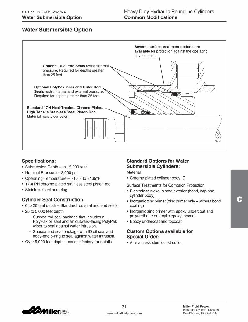
Heavy Duty Hydraulic Roundline CylindersCommon Modifications
www.millerfluidpower.com
Catalog HY08-M1320-1/NA
31 Miller Fluid PowerIndustrial Cylinder DivisionDes Plaines, Illinois USA
C
Water Submersible Option
Optional PolyPak Inner and Outer Rod Seals resist internal and external pressure. Required for depths greater than 25 feet.
Optional Dual End Seals resist external pressure. Required for depths greater than 25 feet.
Standard 17-4 Heat-Treated, Chrome-Plated, High Tensile Stainless Steel Piston Rod Material resists corrosion.
Several surface treatment options are available for protection against the operating environments.
Water Submersible Option
Specifications:• SubmersionDepth–to15,000feet• NominalPressure–3,000psi• OperatingTemperature–-10°Fto+165°F• 17-4PHchromeplatedstainlesssteelpistonrod• Stainlesssteelnametag
Cylinder Seal Construction:• 0to25feetdepth–Standardrodsealandendseals• 25to5,000feetdepth – Subsearodsealpackagethatincludesa PolyPak oil seal and an outward-facing PolyPak wiper to seal against water intrusion. – SubseaendsealpackagewithIDoilsealand body-end o-ring to seal against water intrusion.• Over5,000feetdepth–consultfactoryfordetails
Standard Options for Water Submersible Cylinders:Material• ChromeplatedcylinderbodyID
Surface Treatments for Corrosion Protection• Electrolessnickelplatedexterior(head,capand
cylinder body)• Inorganiczincprimer(zincprimeronly–withoutbond
coating)• Inorganiczincprimerwithepoxyundercoatand
polyurethane or acrylic epoxy topcoat• Epoxyundercoatandtopcoat
Custom Options available for Special Order:• Allstainlesssteelconstruction

Heavy Duty Hydraulic Roundline CylindersCommon Modifications
Miller Fluid PowerIndustrial Cylinder DivisionDes Plaines, Illinois USAwww.millerfluidpower.com
Catalog HY08-M1320-1/NA
32
How to Order Water Submersible Option
How to order:1. Specify the complete cylinder model number.2. Put an “S” in the model number to indicate a Special Modification.3. Include the 3 digit “Submersible Code” (see below).4. For custom options, provide a complete description or drawing of your requirements.
Submersible Code Whenselectingthesubmersibleoption,anSmustbeplacedintheModelNumber.SelectSubmersibleCodevalues for the required Submersion Depth, Cylinder Body, and Corrosion Protection. See the example Model Number below:
Example: 4.00BBRDHKTS14A24.000 S = Submersible Code 2P1(describesa4"borex24"strokeSeriesRDHcylinderforsubmersionupto5,000feet,withaplaincylinderbodyIDand inorganic zinc primer corrosion protection.)
Feature Code Specification For
Submersion Depth1 Conventional rod seal, rod wiper and end seal Depths to 25 feet2 Submersible rod seal, rod wiper and end seal Depths to 5,000 feet3 Other Specify depth / requirements
Cylinder BodyP Plain cylinder body IDC Chrome plated cylinder body ID
Corrosion Protection
1 Inorganic zinc primerSplash and short term immersion service where equipment is top coated by the customer
3 Electroless nickel plated exterior
4 Inorganic zinc primer, epoxy undercoat, and polyurethane or acrylic epoxy topcoat. Splash and short term immersion service
6 Epoxy base and top coat. Long term immersion service9 Other Specify requirements
Water Submersible Codes and Features SuppliedDepths to 5,000 feet1
Submersible Cylinder Feature
Water Submersible Code1
2P1 2P3 2P4 2P6 2C1 2C3 2C4 2C617-4 PH stainless steel piston rod X X X X X X X XStainless steel nametag X X X X X X X XSubmersible rod seal and wiper X X X X X X X XDual end seals X X X X X X X XChrome plated cylinder body ID X X X XElectroless nickel plated exterior X XInorganic zinc primer X XInorganic zinc primer with topcoats X XEpoxy base and topcoat X X
1 Corresponding submersible codes for depths to 25 feet begin with 1 (e.g. 1P1, 1P3, etc.) and include all of the features marked for 5,000 feet depth exceptSubmersibleRodSeal,RodWiperandEndSeals.
Water Submersible Option
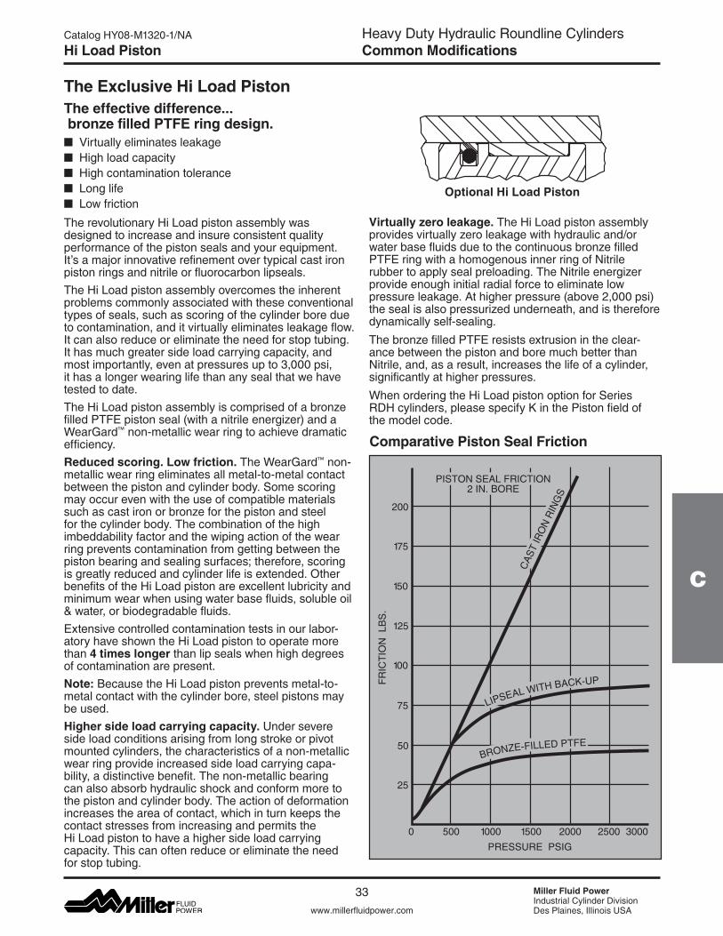
Heavy Duty Hydraulic Roundline CylindersCommon Modifications
www.millerfluidpower.com
Catalog HY08-M1320-1/NA
33 Miller Fluid PowerIndustrial Cylinder DivisionDes Plaines, Illinois USA
C
Hi Load Piston
The effective difference... bronze filled PTFE ring design.n Virtuallyeliminatesleakagen High load capacityn High contamination tolerancen Long lifen Low friction
The revolutionary Hi Load piston assembly was designed to increase and insure consistent quality performance of the piston seals and your equipment. It’s a major innovative refinement over typical cast iron piston rings and nitrile or fluorocarbon lipseals.The Hi Load piston assembly overcomes the inherent problems commonly associated with these conventional types of seals, such as scoring of the cylinder bore due to contamination, and it virtually eliminates leakage flow. It can also reduce or eliminate the need for stop tubing. It has much greater side load carrying capacity, and most importantly, even at pressures up to 3,000 psi, it has a longer wearing life than any seal that we have tested to date. The Hi Load piston assembly is comprised of a bronze filled PTFE piston seal (with a nitrile energizer) and a WearGard™ non-metallic wear ring to achieve dramatic efficiency.Reduced scoring. Low friction. TheWearGard™ non-metallic wear ring eliminates all metal-to-metal contact between the piston and cylinder body. Some scoring may occur even with the use of compatible materials such as cast iron or bronze for the piston and steel for the cylinder body. The combination of the high imbeddability factor and the wiping action of the wear ring prevents contamination from getting between the piston bearing and sealing surfaces; therefore, scoring is greatly reduced and cylinder life is extended. Other benefits of the Hi Load piston are excellent lubricity and minimum wear when using water base fluids, soluble oil & water, or biodegradable fluids.Extensive controlled contamination tests in our labor- atory have shown the Hi Load piston to operate more than 4 times longer than lip seals when high degrees of contamination are present.Note: Because the Hi Load piston prevents metal-to-metal contact with the cylinder bore, steel pistons may be used.Higher side load carrying capacity. Under severe side load conditions arising from long stroke or pivot mounted cylinders, the characteristics of a non-metallic wear ring provide increased side load carrying capa-bility, a distinctive benefit. The non-metallic bearing can also absorb hydraulic shock and conform more to the piston and cylinder body. The action of deformation increases the area of contact, which in turn keeps the contact stresses from increasing and permits the Hi Load piston to have a higher side load carrying capacity. This can often reduce or eliminate the need for stop tubing.
Comparative Piston Seal Friction
200C
AST
IRO
N R
ING
S
PISTON SEAL FRICTION2 IN. BORE
175
150
125
100
75
50
25
0 500 1000 1500 2000 2500 3000PRESSURE PSIG
FRIC
TIO
N L
BS
.
BRONZE-FILLED PTFE
LIPSEAL WITH BACK-UP
The Exclusive Hi Load Piston
Virtually zero leakage. The Hi Load piston assembly provides virtually zero leakage with hydraulic and/or water base fluids due to the continuous bronze filled PTFE ring with a homogenous inner ring of Nitrile rubber to apply seal preloading. The Nitrile energizer provide enough initial radial force to eliminate low pressure leakage. At higher pressure (above 2,000 psi) the seal is also pressurized underneath, and is therefore dynamically self-sealing.The bronze filled PTFE resists extrusion in the clear-ance between the piston and bore much better than Nitrile, and, as a result, increases the life of a cylinder, significantly at higher pressures.WhenorderingtheHiLoadpistonoptionforSeriesRDH cylinders, please specify K in the Piston field of the model code.
Optional Hi Load Piston
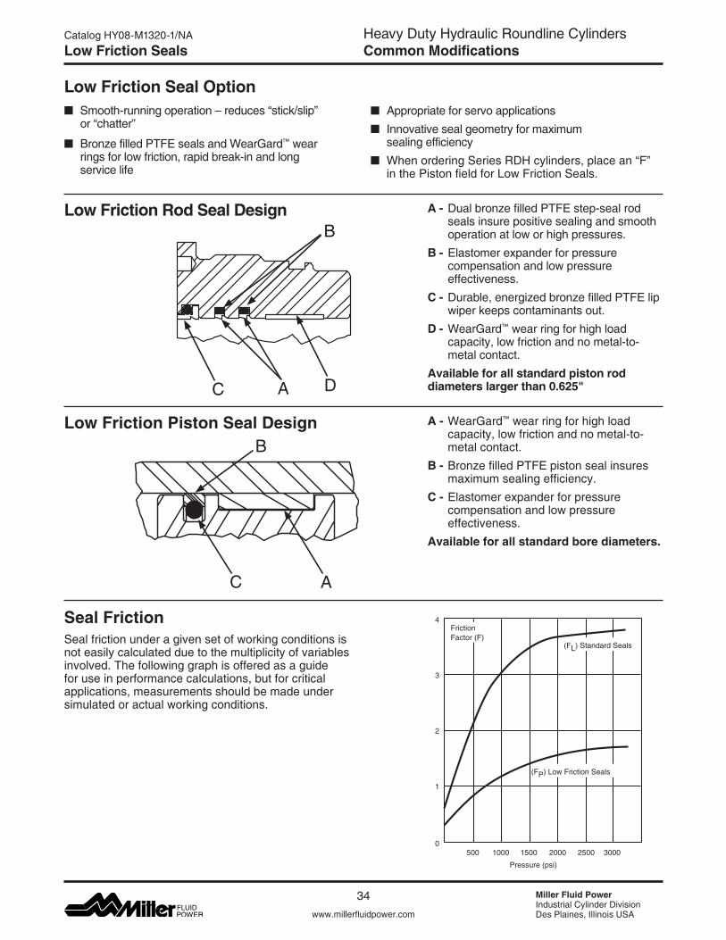
Heavy Duty Hydraulic Roundline CylindersCommon Modifications
Miller Fluid PowerIndustrial Cylinder DivisionDes Plaines, Illinois USAwww.millerfluidpower.com
Catalog HY08-M1320-1/NA
34
Low Friction Seals
nSmooth-runningoperation–reduces“stick/slip” or “chatter”
n BronzefilledPTFEsealsandWearGard™ wear rings for low friction, rapid break-in and long service life
n Appropriate for servo applicationsnInnovative seal geometry for maximum sealing efficiencyn WhenorderingSeriesRDHcylinders,placean“F” in the Piston field for Low Friction Seals.
Low Friction Rod Seal Design A - Dual bronze filled PTFE step-seal rod seals insure positive sealing and smooth operation at low or high pressures.
B - Elastomer expander for pressure compensation and low pressure effectiveness.
C - Durable, energized bronze filled PTFE lip wiper keeps contaminants out.
D -WearGard™ wear ring for high load capacity, low friction and no metal-to-metal contact.
Available for all standard piston rod diameters larger than 0.625"
Low Friction Piston Seal Design A - WearGard™ wear ring for high load capacity, low friction and no metal-to-metal contact.
B - Bronze filled PTFE piston seal insures maximum sealing efficiency.
C - Elastomer expander for pressure compensation and low pressure effectiveness.
Available for all standard bore diameters.
Low Friction Seal Option
B
C A
B
C A
Seal FrictionSeal friction under a given set of working conditions is not easily calculated due to the multiplicity of variables involved. The following graph is offered as a guide for use in performance calculations, but for critical applications, measurements should be made under simulated or actual working conditions.
4
500 1000 1500 2000 2500 3000
Pressure (psi)
3
2
1
0
FrictionFactor (F)
(FL) Standard Seals
(FP) Low Friction Seals
D
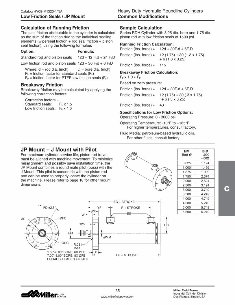
Heavy Duty Hydraulic Roundline CylindersCommon Modifications
www.millerfluidpower.com
Catalog HY08-M1320-1/NA
35 Miller Fluid PowerIndustrial Cylinder DivisionDes Plaines, Illinois USA
C
Low Friction Seals / JP Mount
Calculation of Running FrictionThe seal friction attributable to the cylinder is calculated as the sum of the friction due to the individual sealing elements(wipersealfriction+rodsealfriction+pistonseal friction), using the following formulae:Option: Formula:Standardrodandpistonseals 12d+12FLd+24FLDLowfrictionrodandpistonseals 12d+30Fpd+6FpD Where:d=roddia.(inch) D=boredia.(inch) FL = friction factor for standard seals (FL) Fp = friction factor for PTFE low friction seals (Fp)
Breakaway FrictionBreakaway friction may be calculated by applying the following correction factors: Correctionfactors– Standard seals: FL x 1.5 Low friction seals: Fp x 1.0
Sample CalculationSeries RDH Cylinder with 3.25 dia. bore and 1.75 dia. piston rod with low friction seals at 1500 psi.
Running Friction Calculation:Friction (lbs. force) ≈ 12d+30Fpd+6FpDFriction (lbs. force) ≈ 12(1.75)+30(1.3x1.75) +6(1.3x3.25)Friction (lbs. force) ≈ 115
Breakaway Friction Calculation:Fp x 1.0 ≈ Fp
Based on zero pressure:Friction (lbs. force) ≈ 12d+30Fpd+6FpDFriction (lbs. force) ≈ 12(1.75)+30(.3x1.75) +6(.3x3.25)Friction (lbs. force) ≈ 43
Specifications for Low Friction Options:Operating Pressure: 0 - 3000 psiOperatingTemperature:-10°Fto+165°F. For higher temperatures, consult factory.Fluid Media: petroleum-based hydraulic oils. For other fluids, consult factory.
JP Mount – J Mount with PilotFor maximum cylinder service life, piston rod travel must be aligned with machine movement. To minimize misalignment and possibly save installation time, the JP Mount combines a round male pilot (boss) with the J Mount. This pilot is concentric with the piston rod and can be used to properly locate the cylinder on the machine. Please refer to page 18 for other mount dimensions.
ØB
.125
R.031MAX.
LG + STROKEF
ØUC
ØFC
HD
ZG + STROKE
P + STROKEWF
YF
WØE
FD ±2.5°
ØMM
1.50"-6.00" BORE: 6X ØFB7.00"-8.00" BORE: 8X ØFBEQUALLY SPACED ON ØFC
EE
MM Rod Ø
B Ø +.000 -.002
0.625 1.1241.000 1.4991.375 1.9991.750 2.3742.000 2.6242.500 3.1243.000 3.7493.500 4.2494.000 4.7494.500 5.2495.000 5.7495.500 6.249
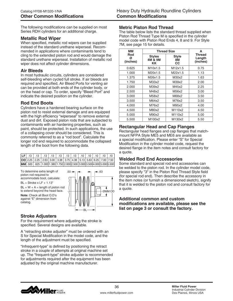
Heavy Duty Hydraulic Roundline CylindersCommon Modifications
Miller Fluid PowerIndustrial Cylinder DivisionDes Plaines, Illinois USAwww.millerfluidpower.com
Catalog HY08-M1320-1/NA
36
Other Common Modifications
.107.005.000
To determine extra length of piston rod required to accommodate boot, calculate:BL=StrokexLF+1.13"BL+W+A=lengthofpistonrodto extend beyond the head face.Note: Check all Boot O.D’s against “E” dimension from catalog.
The following modifications can be supplied on most Series RDH cylinders for an additional charge.
Metallic Rod Wiper Whenspecified,metallicrodwiperscanbesuppliedinstead of the standard urethane wiperseal. Recom-mended in applications where contaminants tend to cling to the extended piston rod and would damage the standard urethane wiperseal. Installation of metallic rod wiper does not affect cylinder dimensions.
Air Bleeds In most hydraulic circuits, cylinders are considered self-bleeding when cycled full stroke. If air bleeds are required and specified, Air Bleed Ports for venting air can be provided at both ends of the cylinder body, or on the head or cap. To order, specify “Bleed Port” and indicate the desired position on the cylinder.
Rod End BootsCylinders have a hardened bearing surface on the piston rod to resist external damage and are equipped with the high efficiency “wiperseal” to remove external dust and dirt. Exposed piston rods that are subjected to contaminants with air hardening properties, such as paint, should be protected. In such applications, the use of a collapsing cover should be considered. This is commonly referred to as a “rod boot”. Calculate the longer rod end required to accommodate the collapsed length of the boot from the following data.
LFODMM
.132.25.500
.132.25.625
.132.631.000
.133.00 1.380
.133.381.750
.133.752.000
.105.133.000
.105.633.500
.106.25 4.000
.107.50 5.500
.50 .63
ØMM
BL
OD
.134.382.500
Stroke AdjustersFor the requirement where adjusting the stroke is specified. Several designs are available.
A “retracting stroke adjuster” must be ordered with an S for Special Modification in the model code, and the length of the adjustment must be specified.
“Infrequent-type” is defined by positioning the retract stroke in a couple of attempts at original machine set up. The “frequent-type” stroke adjuster is recommended for adjustments required after the equipment has been adjusted by the original machine manufacturer.
Metric Piston Rod Thread The table below lists the standard thread supplied when Piston Rod Thread Type M is specified in the cylinder model code with Piston Rod Ends 4, 8 and 9. For Style 7M, see page 15 for details.
MM Rod
Ø (inches)
Thread Size AThread Length(inches)
Styles 4M & 9M
KK
Style 8M CC
0.625 M10x1.5 M12x1.5 0.751.000 M20x1.5 M22x1.5 1.131.375 M26x1.5 M30x2 1.631.750 M33x2 M39x2 2.002.000 M39x2 M45x2 2.252.500 M48x2 M56x2 3.003.000 M58x2 M68x2 3.503.500 M64x2 M76x2 3.504.000 M76x2 M95x2 4.004.500 M80x2 M110x2 4.505.000 M90x2 M110x2 5.005.500 M100x2 M130x2 5.50
Rectangular Head and Cap FlangesRectangular head flanges and cap flanges that match-mount NFPA Style ME5 and ME6 are available as a special modification. Please enter “S” for Special Modification in the cylinder model code, request the desired flange in the item notes and consult factory for a quote.
Welded Rod End Accessories Some standard and special rod end accessories can be welded to the piston rod. In the cylinder model code, pleasespecify"3"inthePistonRodThreadStylefield(for special rod end). Then describe the accessory in the item notes (or furnish a dimensioned sketch), signify that it is welded to the piston rod and consult factory for a quote.
Additional common and custom modifications are available, please see the list on page 3 or consult the factory.
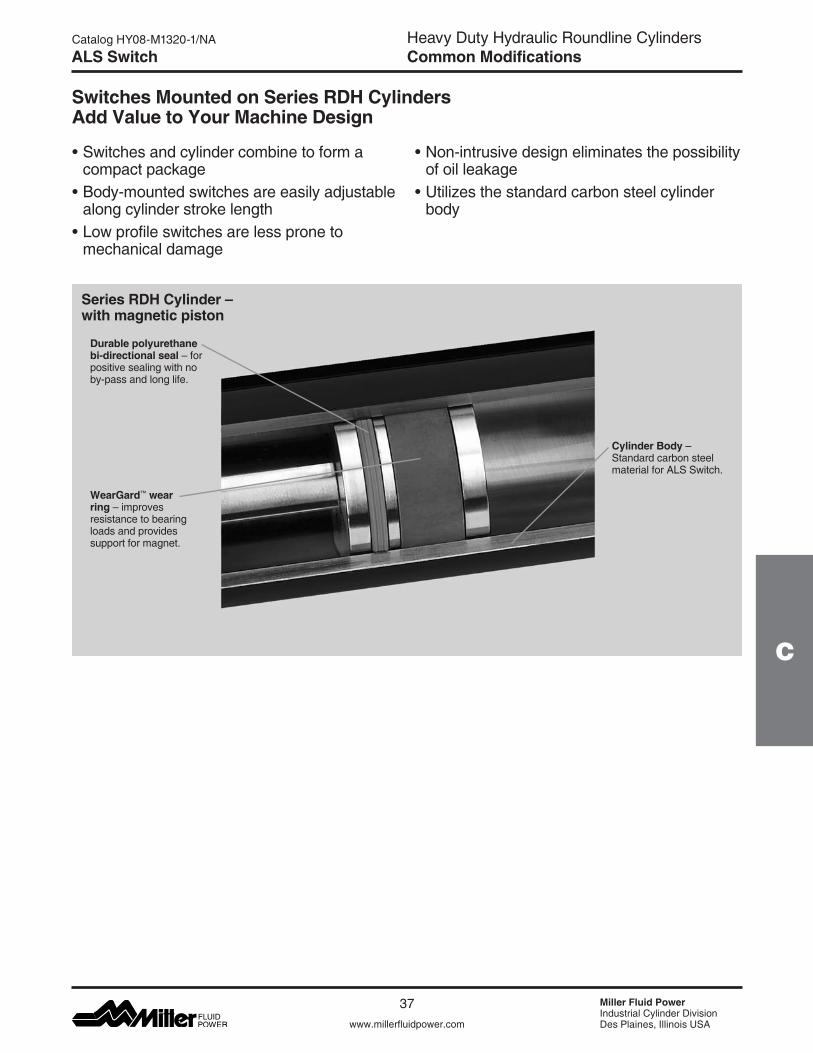
Heavy Duty Hydraulic Roundline CylindersCommon Modifications
www.millerfluidpower.com
Catalog HY08-M1320-1/NA
37 Miller Fluid PowerIndustrial Cylinder DivisionDes Plaines, Illinois USA
C
ALS Switch
•Switchesandcylindercombinetoformacompact package•Body-mountedswitchesareeasilyadjustable
along cylinder stroke length•Lowprofileswitchesarelessproneto
mechanical damage
Durable polyurethane bi-directional seal –forpositive sealing with no by-pass and long life.
Cylinder Body –Standard carbon steel material for ALS Switch.
WearGard™ wear ring –improvesresistance to bearing loads and provides support for magnet.
Series RDH Cylinder – with magnetic piston
•Non-intrusivedesigneliminatesthepossibilityof oil leakage•Utilizesthestandardcarbonsteelcylinder
body
Switches Mounted on Series RDH Cylinders Add Value to Your Machine Design
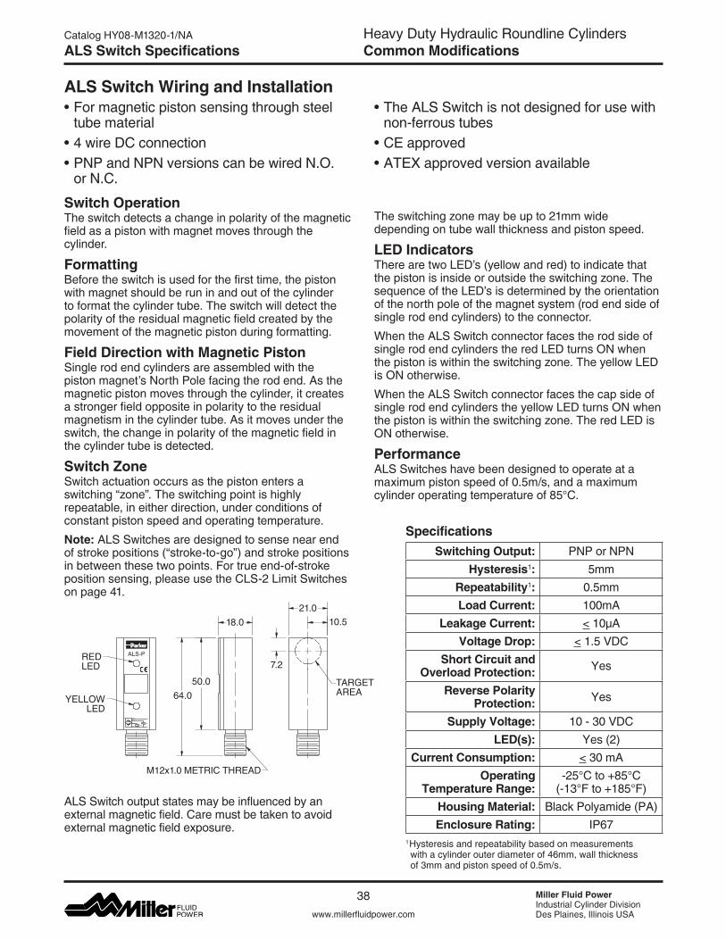
Heavy Duty Hydraulic Roundline CylindersCommon Modifications
Miller Fluid PowerIndustrial Cylinder DivisionDes Plaines, Illinois USAwww.millerfluidpower.com
Catalog HY08-M1320-1/NA
38
ALS Switch Specifications
ALS Switch Wiring and Installation•Formagneticpistonsensingthroughsteel
tube material•4wireDCconnection•PNPandNPNversionscanbewiredN.O.
or N.C.
•TheALSSwitchisnotdesignedforusewithnon-ferrous tubes•CEapproved•ATEXapprovedversionavailable
Switch OperationThe switch detects a change in polarity of the magnetic field as a piston with magnet moves through the cylinder.
FormattingBefore the switch is used for the first time, the piston with magnet should be run in and out of the cylinder to format the cylinder tube. The switch will detect the polarity of the residual magnetic field created by the movement of the magnetic piston during formatting.
Field Direction with Magnetic PistonSingle rod end cylinders are assembled with the piston magnet’s North Pole facing the rod end. As the magnetic piston moves through the cylinder, it creates a stronger field opposite in polarity to the residual magnetism in the cylinder tube. As it moves under the switch, the change in polarity of the magnetic field in the cylinder tube is detected.
Switch ZoneSwitch actuation occurs as the piston enters a switching “zone”. The switching point is highly repeatable, in either direction, under conditions of constant piston speed and operating temperature.
Note: ALS Switches are designed to sense near end of stroke positions (“stroke-to-go”) and stroke positions in between these two points. For true end-of-stroke position sensing, please use the CLS-2 Limit Switches on page 41.
The switching zone may be up to 21mm wide depending on tube wall thickness and piston speed.
LED IndicatorsThere are two LED’s (yellow and red) to indicate that the piston is inside or outside the switching zone. The sequence of the LED’s is determined by the orientation of the north pole of the magnet system (rod end side of single rod end cylinders) to the connector.
WhentheALSSwitchconnectorfacestherodsideofsingle rod end cylinders the red LED turns ON when the piston is within the switching zone. The yellow LED is ON otherwise.
WhentheALSSwitchconnectorfacesthecapsideof single rod end cylinders the yellow LED turns ON when the piston is within the switching zone. The red LED is ON otherwise.
PerformanceALS Switches have been designed to operate at a maximum piston speed of 0.5m/s, and a maximum cylinderoperatingtemperatureof85°C.
YELLOWLED
REDLED
Black
A2
White
Blue
Brown
N.C. Load
N.O.
(+)
Load
(-)
ALS-P
64.050.0
M12x1.0 METRIC THREAD
7.2
10.5
TARGETAREA
18.021.0
SpecificationsSwitching Output: PNP or NPN
Hysteresis1: 5mmRepeatability1: 0.5mmLoad Current: 100mA
Leakage Current: < 10µAVoltage Drop: <1.5VDC
Short Circuit and Overload Protection: Yes
Reverse Polarity Protection: Yes
Supply Voltage: 10-30VDCLED(s): Yes (2)
Current Consumption: < 30 mAOperating
Temperature Range:-25°Cto+85°C (-13°Fto+185°F)
Housing Material: Black Polyamide (PA)Enclosure Rating: IP67
1Hysteresis and repeatability based on measurements with a cylinder outer diameter of 46mm, wall thickness of 3mm and piston speed of 0.5m/s.
ALS Switch output states may be influenced by an external magnetic field. Care must be taken to avoid external magnetic field exposure.
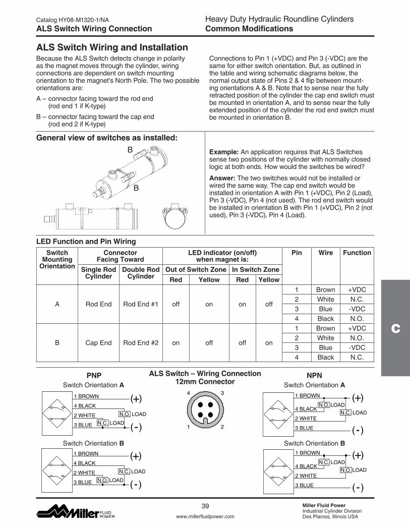
Heavy Duty Hydraulic Roundline CylindersCommon Modifications
www.millerfluidpower.com
Catalog HY08-M1320-1/NA
39 Miller Fluid PowerIndustrial Cylinder DivisionDes Plaines, Illinois USA
C
ALS Switch Wiring Connection
ALS Switch – Wiring Connection12mm Connector
34
21
PNP
N.O. LOAD
1 BROWN
4 BLACK
2 WHITE
3 BLUE
( )+
( )-LOADN.C.
NPN
N.O.N.C.
LOADLOAD
1 BROWN
4 BLACK
2 WHITE
3 BLUE
( )+
( )-
ALS Switch Wiring and InstallationBecause the ALS Switch detects change in polarity as the magnet moves through the cylinder, wiring connections are dependent on switch mounting orientation to the magnet’s North Pole. The two possible orientations are:
A–connectorfacingtowardtherodend (rod end 1 if K-type)
B–connectorfacingtowardthecapend (rod end 2 if K-type)
ConnectionstoPin1(+VDC)andPin3(-VDC)arethesame for either switch orientation. But, as outlined in the table and wiring schematic diagrams below, the normal output state of Pins 2 & 4 flip between mount-ing orientations A & B. Note that to sense near the fully retracted position of the cylinder the cap end switch must be mounted in orientation A, and to sense near the fully extended position of the cylinder the rod end switch must be mounted in orientation B.
General view of switches as installed:
Example: An application requires that ALS Switches sense two positions of the cylinder with normally closed logicatbothends.Howwouldtheswitchesbewired?
Answer: The two switches would not be installed or wired the same way. The cap end switch would be installedinorientationAwithPin1(+VDC),Pin2(Load),Pin3(-VDC),Pin4(notused).TherodendswitchwouldbeinstalledinorientationBwithPin1(+VDC),Pin2(notused),Pin3(-VDC),Pin4(Load).
Switch Mounting
Orientation
Connector Facing Toward
LED indicator (on/off) when magnet is:
Pin Wire Function
Single Rod Cylinder
Double Rod Cylinder
Out of Switch Zone In Switch ZoneRed Yellow Red Yellow
A Rod End Rod End #1 off on on off
1 Brown +VDC2 White N.C.3 Blue -VDC4 Black N.O.
B Cap End Rod End #2 on off off on
1 Brown +VDC2 White N.O.3 Blue -VDC4 Black N.C.
LED Function and Pin Wiring
Switch Orientation A Switch Orientation A
Switch Orientation B Switch Orientation B
N.O. LOAD
1 BROWN
4 BLACK
2 WHITE
3 BLUE
( )+
( )-LOADN.C.
N.O.N.C.
LOADLOAD
1 BROWN
4 BLACK
2 WHITE
3 BLUE
( )+
( )-
B
B
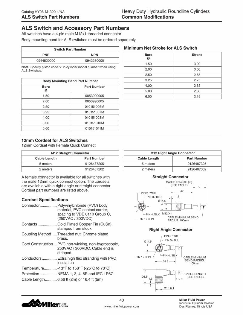
Heavy Duty Hydraulic Roundline CylindersCommon Modifications
Miller Fluid PowerIndustrial Cylinder DivisionDes Plaines, Illinois USAwww.millerfluidpower.com
Catalog HY08-M1320-1/NA
40
ALS Switch Part Numbers
ALS Switch and Accessory Part NumbersAll switches have a 4-pin male M12x1 threaded connector.
Minimum Net Stroke for ALS SwitchBore
Ø Stroke
1.50 3.00
2.00 3.00
2.50 2.88
3.25 2.75
4.00 2.63
5.00 2.38
6.00 2.19
12mm Cordset for ALS Switches12mmCordsetwithFemaleQuickConnect
M12 Straight ConnectorCable Length Part Number
5 meters 9126487205
2 meters 9126487202
M12 Right Angle ConnectorCable Length Part Number
5 meters 9126487305
2 meters 9126487302
Cordset SpecificationsConnector ................Polyvinylchloride(PVC)body
material,PVCcontactcarrier,spacingtoVDE0110GroupC,(250VAC/300VDC)
Contacts ..................GoldPlatedCopperTin(CuSn),stamped from stock.
Coupling Method ..... Threaded nut: Chrome plated brass.
Cord Construction ...PVCnon-wicking,non-hygroscopic, 250VAC/300VDC.Cableendisstripped.
Conductors ..............ExtrahighflexstrandingwithPVCinsulation
Temperature ............ -13°Fto158°F(-25°Cto70°C)Protection ................ NEMA 1, 3, 4, 6P and IEC 1P67Cable Length ........... 6.56 ft (2m) or 16.4 ft (5m)
A female connector is available for all switches with the male 12mm quick connect option. The cordsets are available with a right angle or straight connector. Cordset part numbers are listed above.
Straight Connector
Right Angle Connector
42
Ø14.5
CABLE LENGTH (m)(SEE TABLE)
1.5
PIN 4 /BLK
PIN 2 / WHTPIN 3 / BLU
M12 X 1CABLE MINIMUM BENDRADIUS: 100mmPIN 1 / BRN
CABLE MINIMUMBEND RADIUS:
100mm
CABLE LENGTH(SEE TABLE)
M12 X 1
1.526.5
PIN 2 / WHT
PIN 3 / BLU
PIN 4 / BLKPIN 1 / BRN38.3
Ø14.5
Body mounting band for ALS switches must be ordered separately.
Note: Specify piston code ‘7’ in cylinder model number when using ALS Switches.
Switch Part Number
PNP NPN
0944520000 0942230000
Body Mounting Band Part Number
Bore Ø
Part Number
1.50 0853990005
2.00 0853990005
2.50 010151006M
3.25 010151007M
4.00 010151008M
5.00 010151010M
6.00 010151011M
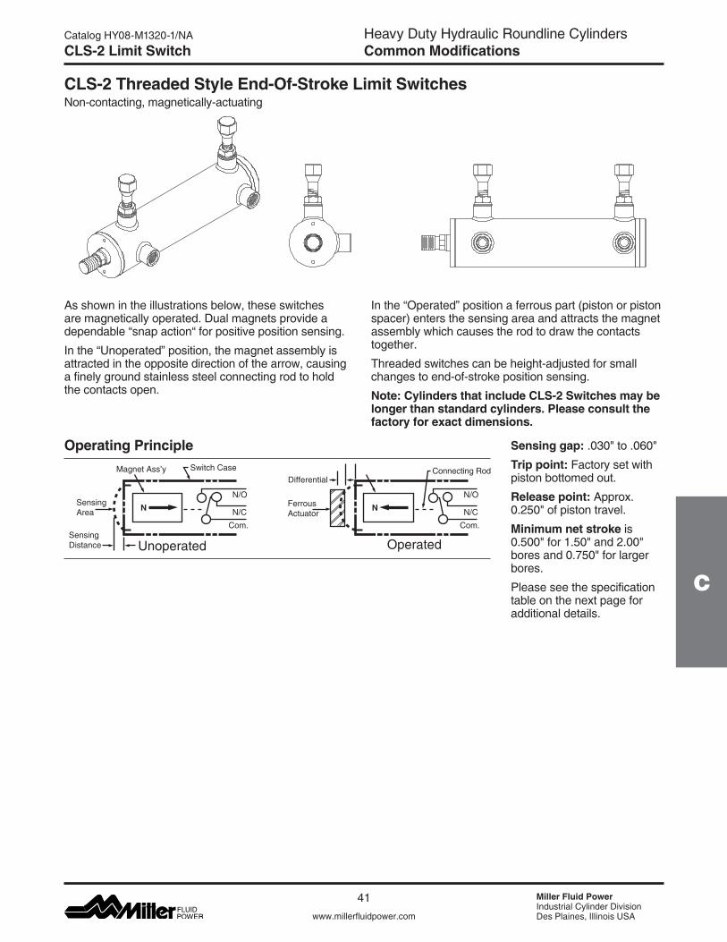
Heavy Duty Hydraulic Roundline CylindersCommon Modifications
www.millerfluidpower.com
Catalog HY08-M1320-1/NA
41 Miller Fluid PowerIndustrial Cylinder DivisionDes Plaines, Illinois USA
C
CLS-2 Limit Switch
CLS-2 Threaded Style End-Of-Stroke Limit SwitchesNon-contacting, magnetically-actuating
As shown in the illustrations below, these switches are magnetically operated. Dual magnets provide a dependable “snap action“ for positive position sensing.
In the “Unoperated” position, the magnet assembly is attracted in the opposite direction of the arrow, causing a finely ground stainless steel connecting rod to hold the contacts open.
SensingArea
SensingDistance
Magnet Ass’y Switch Case
N/O
N/CCom.
Unoperated
N FerrousActuator
DifferentialConnecting Rod
N/O
N/CCom.
Operated
N
Operating Principle Sensing gap: .030"to.060"Trip point: Factory set with piston bottomed out.
Release point: Approx. 0.250"ofpistontravel.
Minimum net stroke is 0.500"for1.50"and2.00"boresand0.750"forlargerbores.
Please see the specification table on the next page for additional details.
In the “Operated” position a ferrous part (piston or piston spacer) enters the sensing area and attracts the magnet assembly which causes the rod to draw the contacts together.
Threaded switches can be height-adjusted for small changes to end-of-stroke position sensing.
Note: Cylinders that include CLS-2 Switches may be longer than standard cylinders. Please consult the factory for exact dimensions.
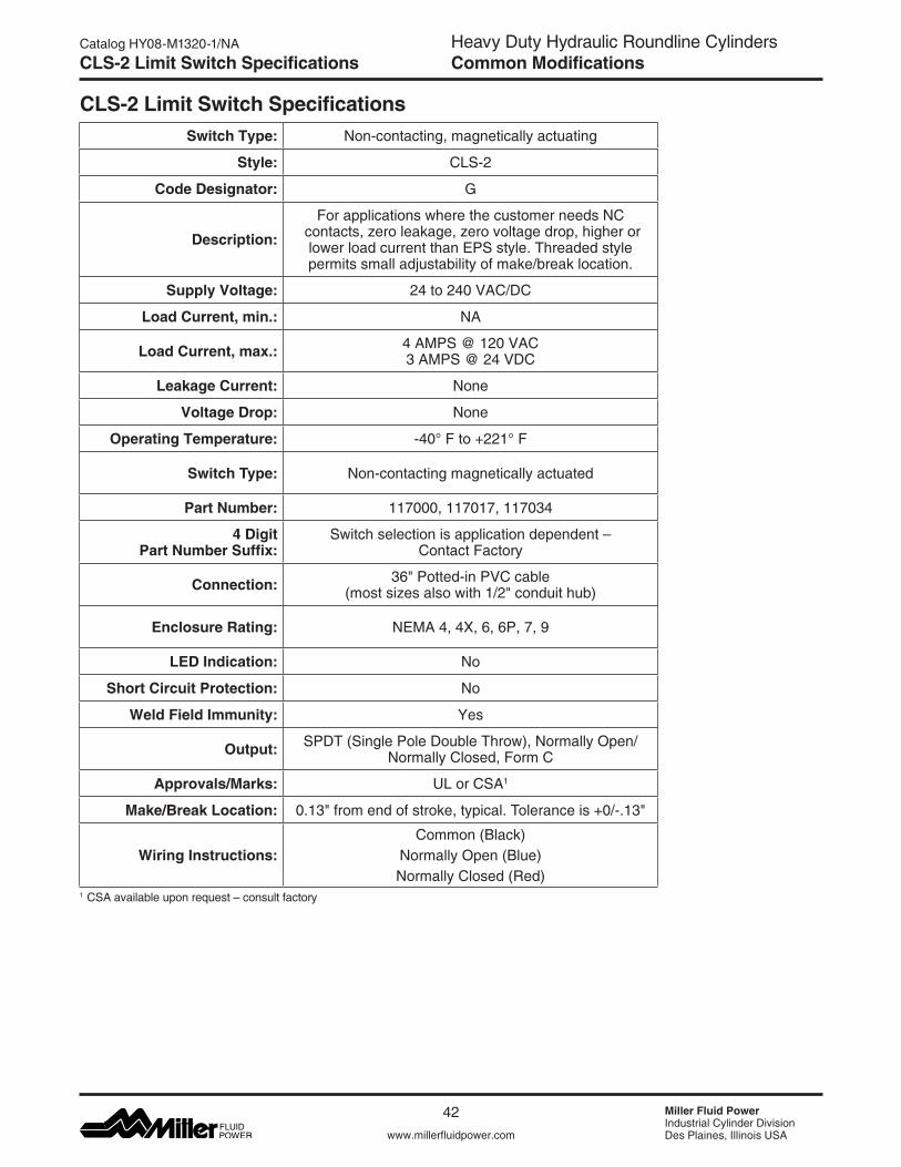
Heavy Duty Hydraulic Roundline CylindersCommon Modifications
Miller Fluid PowerIndustrial Cylinder DivisionDes Plaines, Illinois USAwww.millerfluidpower.com
Catalog HY08-M1320-1/NA
42
CLS-2 Limit Switch SpecificationsSwitch Type: Non-contacting, magnetically actuating
Style: CLS-2
Code Designator: G
Description:For applications where the customer needs NC
contacts, zero leakage, zero voltage drop, higher or lower load current than EPS style. Threaded style permits small adjustability of make/break location.
Supply Voltage: 24to240VAC/DC
Load Current, min.: NA
Load Current, max.: 4AMPS@120VAC3AMPS@24VDC
Leakage Current: None
Voltage Drop: None
Operating Temperature: -40°Fto+221°F
Switch Type: Non-contacting magnetically actuated
Part Number: 117000, 117017, 117034
4 Digit Part Number Suffix:
Switchselectionisapplicationdependent– Contact Factory
Connection: 36"Potted-inPVCcable (mostsizesalsowith1/2"conduithub)
Enclosure Rating: NEMA 4, 4X, 6, 6P, 7, 9
LED Indication: No
Short Circuit Protection: No
Weld Field Immunity: Yes
Output: SPDT (Single Pole Double Throw), Normally Open/Normally Closed, Form C
Approvals/Marks: UL or CSA1
Make/Break Location: 0.13"fromendofstroke,typical.Toleranceis+0/-.13"
Wiring Instructions:Common (Black)
Normally Open (Blue)Normally Closed (Red)
CLS-2 Limit Switch Specifications
1 CSAavailableuponrequest–consultfactory
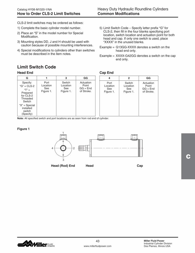
Heavy Duty Hydraulic Roundline CylindersCommon Modifications
www.millerfluidpower.com
Catalog HY08-M1320-1/NA
43 Miller Fluid PowerIndustrial Cylinder DivisionDes Plaines, Illinois USA
C
How to Order CLS-2 Limit Switches
CLS-2 limit switches may be ordered as follows:
1) Complete the basic cylinder model number.
2) Place an “S” in the model number for Special Modification.
3) Mounting styles DD, J and H should be used with caution because of possible mounting interferences.
4) Special modifications to cylinders other than switches must be described in the item notes.
Head EndG 1 3 GG
Specify:“G”=CLS-2
“T” = Prepared for CLS-2 Threaded
Switch“X” = Special
installed switch
(Specify)
Port Location
See Figure 1.
Switch Location
See Figure 1.
Actuation Point
GG=End of Stroke.
Cap End4 2 GG
Port Location
See Figure 1.
Switch Location
See Figure 1.
Actuation Point
GG=End of Stroke.
Note: All specified switch and port locations are as seen from rod end of cylinder.
5)LimitSwitchCode–Specifyletterprefix“G”forCLS-2, then fill in the four blanks specifying port location, switch location and actuation point for both head and cap. If only one switch is used, place “XXXX” in the unused blanks.
Example=G13GG-XXXXdenotesaswitchonthehead end only.
Example=XXXX-G42GGdenotesaswitchonthecapend only.
Head (Rod) End Head Cap
1
2
3
4
Limit Switch Code
Figure 1

Heavy Duty Hydraulic Roundline CylindersEngineering Data
Miller Fluid PowerIndustrial Cylinder DivisionDes Plaines, Illinois USAwww.millerfluidpower.com
Catalog HY08-M1320-1/NA
44
Notes
Notes
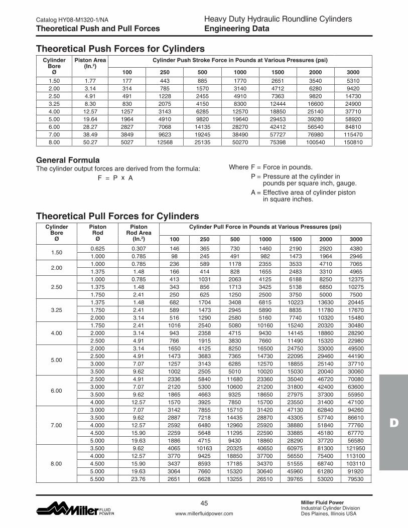
Heavy Duty Hydraulic Roundline CylindersEngineering Data
D
www.millerfluidpower.com
Catalog HY08-M1320-1/NA
45 Miller Fluid PowerIndustrial Cylinder DivisionDes Plaines, Illinois USA
Theoretical Push and Pull Forces
General FormulaThe cylinder output forces are derived from the formula: F = P x A
Theoretical Push Forces for Cylinders Cylinder
Bore Ø
Piston Area (In.2)
Cylinder Push Stroke Force in Pounds at Various Pressures (psi)
100 250 500 1000 1500 2000 30001.50 1.77 177 443 885 1770 2651 3540 53102.00 3.14 314 785 1570 3140 4712 6280 94202.50 4.91 491 1228 2455 4910 7363 9820 147303.25 8.30 830 2075 4150 8300 12444 16600 249004.00 12.57 1257 3143 6285 12570 18850 25140 377105.00 19.64 1964 4910 9820 19640 29453 39280 589206.00 28.27 2827 7068 14135 28270 42412 56540 848107.00 38.49 3849 9623 19245 38490 57727 76980 1154708.00 50.27 5027 12568 25135 50270 75398 100540 150810
Theoretical Pull Forces for Cylinders Cylinder
Bore Ø
Piston Rod
Ø
Piston Rod Area
(In.2)
Cylinder Pull Force in Pounds at Various Pressures (psi)
100 250 500 1000 1500 2000 3000
1.500.625 0.307 146 365 730 1460 2190 2920 43801.000 0.785 98 245 491 982 1473 1964 2946
2.001.000 0.785 236 589 1178 2355 3533 4710 70651.375 1.48 166 414 828 1655 2483 3310 4965
2.501.000 0.785 413 1031 2063 4125 6188 8250 123751.375 1.48 343 856 1713 3425 5138 6850 102751.750 2.41 250 625 1250 2500 3750 5000 7500
3.251.375 1.48 682 1704 3408 6815 10223 13630 204451.750 2.41 589 1473 2945 5890 8835 11780 176702.000 3.14 516 1290 2580 5160 7740 10320 15480
4.001.750 2.41 1016 2540 5080 10160 15240 20320 304802.000 3.14 943 2358 4715 9430 14145 18860 282902.500 4.91 766 1915 3830 7660 11490 15320 22980
5.00
2.000 3.14 1650 4125 8250 16500 24750 33000 495002.500 4.91 1473 3683 7365 14730 22095 29460 441903.000 7.07 1257 3143 6285 12570 18855 25140 377103.500 9.62 1002 2505 5010 10020 15030 20040 30060
6.00
2.500 4.91 2336 5840 11680 23360 35040 46720 700803.000 7.07 2120 5300 10600 21200 31800 42400 636003.500 9.62 1865 4663 9325 18650 27975 37300 559504.000 12.57 1570 3925 7850 15700 23550 31400 47100
7.00
3.000 7.07 3142 7855 15710 31420 47130 62840 942603.500 9.62 2887 7218 14435 28870 43305 57740 866104.000 12.57 2592 6480 12960 25920 38880 51840 777604.500 15.90 2259 5648 11295 22590 33885 45180 677705.000 19.63 1886 4715 9430 18860 28290 37720 56580
8.00
3.500 9.62 4065 10163 20325 40650 60975 81300 1219504.000 12.57 3770 9425 18850 37700 56550 75400 1131004.500 15.90 3437 8593 17185 34370 51555 68740 1031105.000 19.63 3064 7660 15320 30640 45960 61280 919205.500 23.76 2651 6628 13255 26510 39765 53020 79530
WhereF=Forceinpounds. P = Pressure at the cylinder in pounds per square inch, gauge. A = Effective area of cylinder piston in square inches.
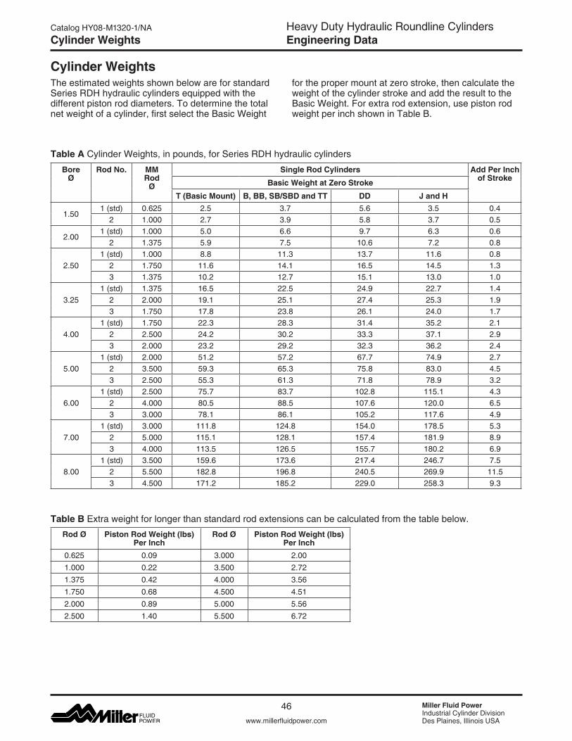
Heavy Duty Hydraulic Roundline CylindersEngineering Data
Miller Fluid PowerIndustrial Cylinder DivisionDes Plaines, Illinois USAwww.millerfluidpower.com
Catalog HY08-M1320-1/NA
46
Cylinder Weights
The estimated weights shown below are for standard Series RDH hydraulic cylinders equipped with the different piston rod diameters. To determine the total netweightofacylinder,firstselecttheBasicWeight
Table A CylinderWeights,inpounds,forSeriesRDHhydrauliccylinders
for the proper mount at zero stroke, then calculate the weight of the cylinder stroke and add the result to the BasicWeight.Forextrarodextension,usepistonrodweight per inch shown in Table B.
Table B Extra weight for longer than standard rod extensions can be calculated from the table below.
Rod Ø Piston Rod Weight (lbs) Per Inch
Rod Ø Piston Rod Weight (lbs) Per Inch
0.625 0.09 3.000 2.001.000 0.22 3.500 2.721.375 0.42 4.000 3.561.750 0.68 4.500 4.512.000 0.89 5.000 5.562.500 1.40 5.500 6.72
Bore Ø
Rod No. MM Rod
Ø
Single Rod Cylinders Add Per Inch of StrokeBasic Weight at Zero Stroke
T (Basic Mount) B, BB, SB/SBD and TT DD J and H
1.501 (std) 0.625 2.5 3.7 5.6 3.5 0.4
2 1.000 2.7 3.9 5.8 3.7 0.5
2.001 (std) 1.000 5.0 6.6 9.7 6.3 0.6
2 1.375 5.9 7.5 10.6 7.2 0.8
2.501 (std) 1.000 8.8 11.3 13.7 11.6 0.8
2 1.750 11.6 14.1 16.5 14.5 1.33 1.375 10.2 12.7 15.1 13.0 1.0
3.251 (std) 1.375 16.5 22.5 24.9 22.7 1.4
2 2.000 19.1 25.1 27.4 25.3 1.93 1.750 17.8 23.8 26.1 24.0 1.7
4.001 (std) 1.750 22.3 28.3 31.4 35.2 2.1
2 2.500 24.2 30.2 33.3 37.1 2.93 2.000 23.2 29.2 32.3 36.2 2.4
5.001 (std) 2.000 51.2 57.2 67.7 74.9 2.7
2 3.500 59.3 65.3 75.8 83.0 4.53 2.500 55.3 61.3 71.8 78.9 3.2
6.001 (std) 2.500 75.7 83.7 102.8 115.1 4.3
2 4.000 80.5 88.5 107.6 120.0 6.53 3.000 78.1 86.1 105.2 117.6 4.9
7.001 (std) 3.000 111.8 124.8 154.0 178.5 5.3
2 5.000 115.1 128.1 157.4 181.9 8.93 4.000 113.5 126.5 155.7 180.2 6.9
8.001 (std) 3.500 159.6 173.6 217.4 246.7 7.5
2 5.500 182.8 196.8 240.5 269.9 11.53 4.500 171.2 185.2 229.0 258.3 9.3
Cylinder Weights
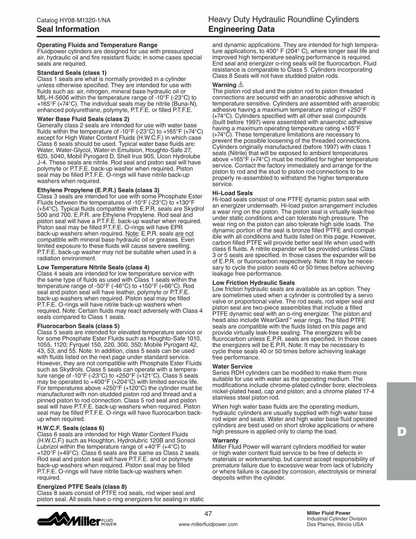
Heavy Duty Hydraulic Roundline CylindersEngineering Data
D
www.millerfluidpower.com
Catalog HY08-M1320-1/NA
47 Miller Fluid PowerIndustrial Cylinder DivisionDes Plaines, Illinois USA
Seal Information
Operating Fluids and Temperature Range Fluidpower cylinders are designed for use with pressurized air, hydraulic oil and fire resistant fluids; in some cases special seals are required.Standard Seals (class 1) Class 1 seals are what is normally provided in a cylinder unless otherwise specified. They are intended for use with fluids such as: air, nitrogen, mineral base hydraulic oil or MIL-H-5606withinthetemperaturerangeof-10°F(-23°C)to+165°F(+74°C).Theindividualsealsmaybenitrile(Buna-N),enhanced polyurethane, polymyte, P.T.F.E. or filled P.T.F.E.Water Base Fluid Seals (class 2) Generallyclass2sealsareintendedforusewithwaterbasefluidswithinthetemperatureof-10°F(-23°C)to+165°F(+74°C)exceptforHighWaterContentFluids(H.W.C.F.)inwhichcaseClass 6 seals should be used. Typical water base fluids are: Water,Water-Glycol,Water-inEmulsion,Houghto-Safe27,620, 5040, Mobil Pyrogard D, Shell Irus 905, Ucon Hydrolube J-4. These seals are nitrile. Rod seal and piston seal will have polymyte or P.T.F.E. back-up washer when required. Piston seal may be filled P.T.F.E. O-rings will have nitrile back-up washers when required.Ethylene Propylene (E.P.R.) Seals (class 3) Class 3 seals are intended for use with some Phosphate Ester Fluidsbetweenthetemperaturesof-10°F(-23°C)to+130°F(+54°C).TypicalfluidscompatiblewithE.P.R.sealsareSkydrol500 and 700. E.P.R. are Ethylene Propylene. Rod seal and piston seal will have a P.T.F.E. back-up washer when required. Piston seal may be filled P.T.F.E. O-rings will have EPR back-up washers when required. Note: E.P.R. seals are not compatible with mineral base hydraulic oil or greases. Even limited exposure to these fluids will cause severe swelling. P.T.F.E. back-up washer may not be suitable when used in a radiation environment.Low Temperature Nitrile Seals (class 4) Class 4 seals are intended for low temperature service with the same type of fluids as used with Class 1 seals within the temperaturerangeof-50°F(-46°C)to+150°F(+66°C).Rodseal and piston seal will have leather, polymyte or P.T.F.E. back-up washers when required. Piston seal may be filled P.T.F.E. O-rings will have nitrile back-up washers when required. Note: Certain fluids may react adversely with Class 4 seals compared to Class 1 seals.Fluorocarbon Seals (class 5) Class 5 seals are intended for elevated temperature service or for some Phosphate Ester Fluids such as Houghto-Safe 1010, 1055, 1120; Fyrquel 150, 220, 300, 350; Mobile Pyrogard 42, 43, 53, and 55. Note: In addition, class 5 seals can be used with fluids listed on the next page under standard service. However, they are not compatible with Phosphate Ester Fluids such as Skydrols. Class 5 seals can operate with a tempera-turerangeof-10°F(-23°C)to+250°F(+121°C).Class5sealsmaybeoperatedto+400°F(+204°C)withlimitedservicelife.Fortemperaturesabove+250°F(+120°C)thecylindermustbemanufactured with non-studded piston rod and thread and a pinned piston to rod connection. Class 5 rod seal and piston seal will have P.T.F.E. back-up washers when required. Piston seal may be filled P.T.F.E. O-rings will have fluorocarbon back-up when required.H.W.C.F. Seals (class 6) Class6sealsareintendedforHighWaterContentFluids(H.W.C.F.)suchasHoughton,Hydrolubric120BandSonsol Lubrizolwithinthetemperaturerangeof+40°F(+4°C)to+120°F(+49°C).Class6sealsarethesameasClass2seals.Rod seal and piston seal will have P.T.F.E. and or polymyte back-up washers when required. Piston seal may be filled P.T.F.E. O-rings will have nitrile back-up washers when required. Energized PTFE Seals (class 8) Class 8 seals consist of PTFE rod seals, rod wiper seal and piston seal. All seals have o-ring energizers for sealing in static
and dynamic applications. They are intended for high tempera-tureapplications,to400°F(204°C),wherelongerseallifeandimproved high temperature sealing performance is required. End seal and energizer o-ring seals will be fluorocarbon. Fluid resistance is comparable to Class 5. Cylinders incorporating Class 8 Seals will not have studded piston rods.Warning The piston rod stud and the piston rod to piston threaded connections are secured with an anaerobic adhesive which is temperature sensitive. Cylinders are assembled with anaerobic adhesivehavingamaximumtemperatureratingof+250°F(+74°C).Cylindersspecifiedwithallothersealcompounds(built before 1997) were assembled with anaerobic adhesive havingamaximumoperatingtemperaturerating+165°F(+74°C).Thesetemperaturelimitationsarenecessarytoprevent the possible loosening of the threaded connections. Cylinders originally manufactured (before 1997) with class 1 seals (Nitrile) that will be exposed to ambient temperatures above+165°F(+74°C)mustbemodifiedforhighertemperatureservice. Contact the factory immediately and arrange for the piston to rod and the stud to piston rod connections to be properly re-assembled to withstand the higher temperature service. Hi-Load Seals Hi-load seals consist of one PTFE dynamic piston seal with an energizer underneath. Hi-load piston arrangement includes a wear ring on the piston. The piston seal is virtually leak-free under static conditions and can tolerate high pres sure. The wear ring on the piston can also tolerate high side loads. The dynamic portion of the seal is bronze filled PTFE and compat-ible with all conditions and fluids listed on this page. However, carbon filled PTFE will provide better seal life when used with class 6 fluids. A nitrile expander will be provided unless Class 3 or 5 seals are specified. In those cases the expander will be of E.P.R. or fluorocarbon respectively. Note: It may be neces-sary to cycle the piston seals 40 or 50 times before achieving leakage free performance.Low Friction Hydraulic Seals Low friction hydraulic seals are available as an option. They are sometimes used when a cylinder is controlled by a servo valve or proportional valve. The rod seals, rod wiper seal and piston seal are two-piece assemblies that include a filled PTFE dynamic seal with an o-ring energizer. The piston and headalsoincludeWearGard™ wear rings. The filled PTFE seals are compatible with the fluids listed on this page and provide virtually leak-free sealing. The energizers will be fluoro carbon unless E.P.R. seals are specified. In those cases the energizers will be E.P.R. Note: It may be necessary to cycle these seals 40 or 50 times before achieving leakage free performance.Water Service Series RDH cylinders can be modified to make them more suitable for use with water as the operating medium. The modifications include chrome-plated cylinder bore; electroless nickel-plated head, cap and piston; and a chrome plated 17-4 stainless steel piston rod. Whenhighwaterbasefluidsaretheoperatingmedium,hydraulic cylinders are usually supplied with high water base rodwiperandseals.Waterandhighwaterbasefluidoperatedcylinders are best used on short stroke applications or where high pressure is applied only to clamp the load.Warranty Miller Fluid Power will warrant cylinders modified for water or high water content fluid service to be free of defects in materials or workmanship, but cannot accept responsibility of premature failure due to excessive wear from lack of lubricity or where failure is caused by corrosion, electrolysis or mineral deposits within the cylinder.
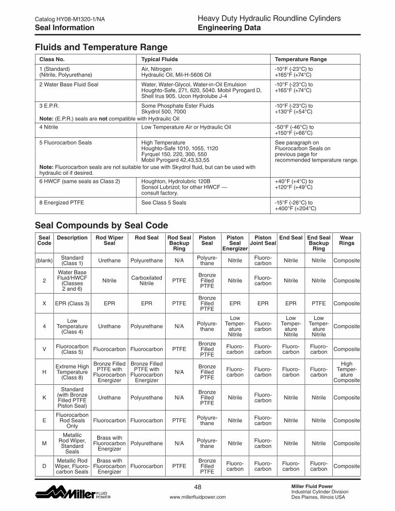
Heavy Duty Hydraulic Roundline CylindersEngineering Data
Miller Fluid PowerIndustrial Cylinder DivisionDes Plaines, Illinois USAwww.millerfluidpower.com
Catalog HY08-M1320-1/NA
48
Seal Information
Temperature Range
-10°F(-23°C)to +165°F(+74°C)
-10°F(-23°C)to +165°F(+74°C)
-10°F(-23°C)to +130°F(+54°C)
-50°F(-46°C)to +150°F(+66°C)
See paragraph on Fluorocarbon Seals on previous page for recommended temperature range.
+40°F(+4°C)to +120°F(+49°C)
-15°F(-26°C)to +400°F(+204°C)
Class No.
1 (Standard) (Nitrile, Polyurethane)
2WaterBaseFluidSeal
3 E.P.R. Note: (E.P.R.) seals are not compatible with Hydraulic Oil4 Nitrile
5 Fluorocarbon Seals Note: Fluorocarbon seals are not suitable for use with Skydrol fluid, but can be used with hydraulic oil if desired.6HWCF(samesealsasClass2)
8 Energized PTFE
Typical Fluids
Air, Nitrogen Hydraulic Oil, Mil-H-5606 Oil
Water,Water-Glycol,Water-in-OilEmulsionHoughto-Safe, 271, 620, 5040. Mobil Pyrogard D, Shell Irus 905. Ucon Hydrolube J-4
Some Phosphate Ester Fluids Skydrol 500, 7000
Low Temperature Air or Hydraulic Oil
High Temperature Houghto-Safe 1010, 1055, 1120 Fyrquel 150, 220, 300, 550 Mobil Pyrogard 42,43,53,55
Houghton, Hydrolubric 120B SonsolLubrizol;forotherHWCF— consult factory.
See Class 5 Seals
Fluids and Temperature Range
Seal Compounds by Seal CodeSeal Code
Description Rod Wiper Seal
Rod Seal Rod Seal Backup
Ring
Piston Seal
Piston Seal
Energizer
Piston Joint Seal
End Seal End Seal Backup
Ring
Wear Rings
(blank) Standard (Class 1) Urethane Polyurethane N/A Polyure-
thane Nitrile Fluoro-carbon Nitrile Nitrile Composite
2WaterBase Fluid/HWCF
(Classes 2 and 6)
Nitrile Carboxilated Nitrile PTFE
Bronze Filled PTFE
Nitrile Fluoro-carbon Nitrile Nitrile Composite
X EPR (Class 3) EPR EPR PTFEBronze Filled PTFE
EPR EPR EPR PTFE Composite
4Low
Temper ature (Class 4)
Urethane Polyurethane N/A Polyure-thane
Low Temper-
ature Nitrile
Fluoro-carbon
Low Temper-
ature Nitrile
Low Temper-
ature Nitrile
Composite
V Fluoro carbon (Class 5) Fluoro carbon Fluoro carbon PTFE
Bronze Filled PTFE
Fluoro-carbon
Fluoro-carbon
Fluoro-carbon
Fluoro-carbon Composite
HExtreme High Temper ature
(Class 8)
Bronze Filled PTFE with
Fluoro carbon Energizer
Bronze Filled PTFE with
Fluoro carbon Energizer
N/ABronze Filled PTFE
Fluoro-carbon
Fluoro-carbon
Fluoro-carbon
Fluoro-carbon
High Temper-
ature Composite
KStandard
(with Bronze Filled PTFE Piston Seal)
Urethane Polyurethane N/ABronze Filled PTFE
Nitrile Fluoro-carbon Nitrile Nitrile Composite
EFluoro carbon
Rod Seals Only
Fluoro carbon Fluoro carbon PTFE Polyure-thane Nitrile Fluoro-
carbon Nitrile Nitrile Composite
MMetallic
RodWiper, Standard
Seals
Brass with Fluoro carbon
EnergizerPolyurethane N/A Polyure-
thane Nitrile Fluoro-carbon Nitrile Nitrile Composite
DMetallic Rod Wiper,Fluoro-carbon Seals
Brass with Fluoro carbon
EnergizerFluoro carbon PTFE
Bronze Filled PTFE
Fluoro-carbon
Fluoro-carbon
Fluoro-carbon
Fluoro-carbon Composite
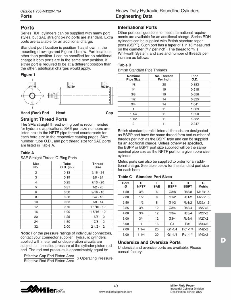
Heavy Duty Hydraulic Roundline CylindersEngineering Data
D
www.millerfluidpower.com
Catalog HY08-M1320-1/NA
49 Miller Fluid PowerIndustrial Cylinder DivisionDes Plaines, Illinois USA
Ports
PortsSeries RDH cylinders can be supplied with many port styles, but SAE straight o-ring ports are standard. Extra ports are available for an additional charge.
Standard port location is position 1 as shown in the mounting drawings and Figure 1 below. Port locations other than position 1 can be specified for no additional charge if both ports are in the same new position. If either port is required to be at a different position than the other, additional charges would apply.
Figure 1
Head (Rod) End Head Cap
Straight Thread PortsThe SAE straight thread o-ring port is recommended for hydraulic applications. SAE port size numbers are listed next to the NPTF pipe thread counterparts for each bore size in the respective catalog pages. Size number, tube O.D., and port thread size for SAE ports are listed in Table A.
Table ASAE Straight Thread O-Ring Ports
Note: For the pressure ratings of individual connectors, contact your connector supplier. Hydraulic cylinders applied with meter out or deceleration circuits are subject to intensified pressure at the cylinder piston rod end. The rod end pressure is approximately equal to:
Effective Cap End Piston Area Effective Rod End Piston Area
x Operating Pressure
Table C – Standard Port Sizes
International PortsOther port configurations to meet international require-ments are available for an additional charge. Series RDH cylinders can be supplied with British standard taper ports (BSPT). Such port has a taper of 1 in 16 measured on the diameter (1/16"perinch).Thethreadformis WhitworthSystem,andsizeandnumberofthreadsperinch are as follows:
Table BBritish Standard Pipe Threads
British standard parallel internal threads are designated as BSPP and have the same thread form and number of threads per inch as the BSPT type and can be supplied for an additional charge. Unless otherwise specified, the BSPP or BSPT port size supplied will be the same nominal pipe size as the NPTF port for a given bore size cylinder.Metric ports can also be supplied to order for an addi-tional charge. See table below for the standard port size for each bore.
1
2
3
4
Bore Ø
U NPTF
T SAE
R BSPP
B BSPT
G Metric
1.50 3/8 6 G3/8 Rc3/8 M18x1.5
2.00 1/2 8 G1/2 Rc1/2 M22x1.5
2.50 1/2 8 G1/2 Rc1/2 M22x1.5
3.25 3/4 12 G3/4 Rc3/4 M27x2
4.00 3/4 12 G3/4 Rc3/4 M27x2
5.00 3/4 12 G3/4 Rc3/4 M27x2
6.00 1 16 G1 Rc1 M33x2
7.00 1 1/4 20 G1-1/4 Rc1-1/4 M42x2
8.00 1 1/4 20 G1-1/4 Rc1-1/4 M42x2
Size No.
Tube O.D. (in.)
Thread Size
2 0.13 5/16 - 243 0.19 3/8 - 244 0.25 7/16 - 205 0.31 1/2 - 206 0.38 9/16 - 188 0.50 3/4 - 16
10 0.63 7/8 - 1412 0.75 1 1/16 - 1216 1.00 1 5/16 - 1220 1.25 1 5/8 - 1224 1.50 1 7/8 - 1232 2.00 2 1/2 - 12
NominalPipe Size
No. ThreadsPer Inch
PipeO.D.
1/8 28 0.3831/4 19 0.5183/8 19 0.6561/2 14 0.8253/4 14 1.0411 11 1.309
1 1/4 11 1.6501 1/2 11 1.882
2 11 2.347
Undersize and Oversize PortsUndersize and oversize ports are available. Please consult factory.
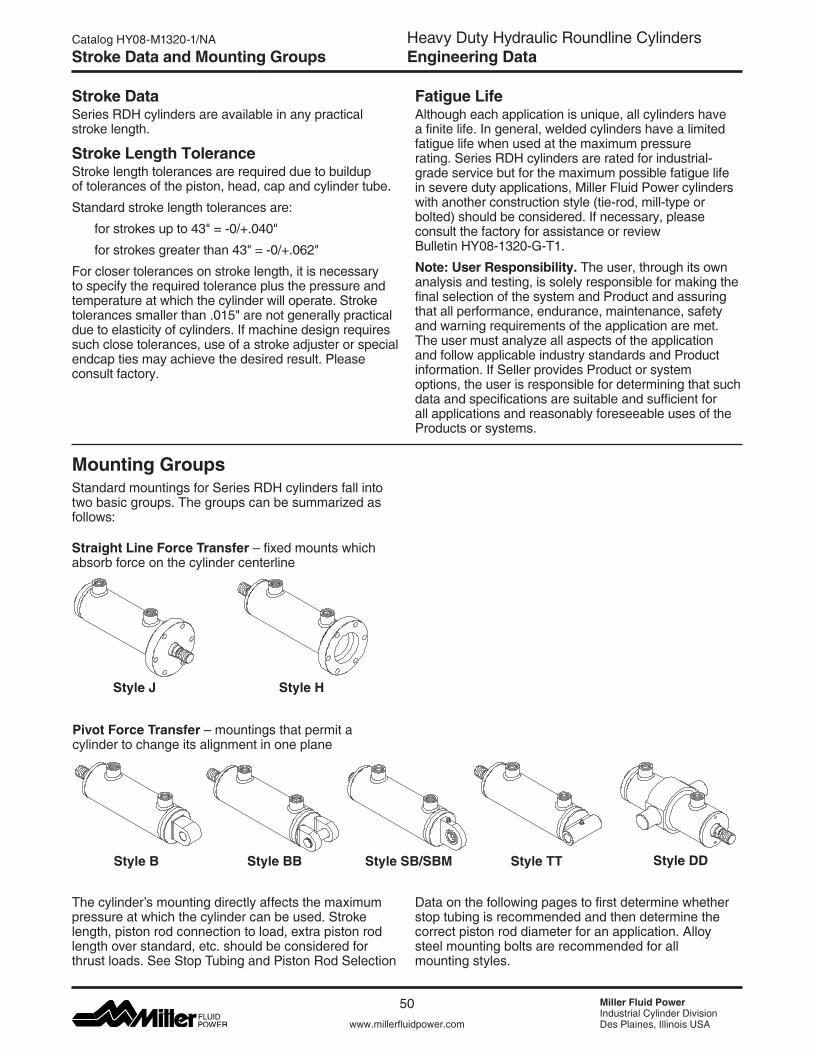
Heavy Duty Hydraulic Roundline CylindersEngineering Data
Miller Fluid PowerIndustrial Cylinder DivisionDes Plaines, Illinois USAwww.millerfluidpower.com
Catalog HY08-M1320-1/NA
50
Stroke Data and Mounting Groups
Stroke DataSeries RDH cylinders are available in any practical stroke length.
Stroke Length ToleranceStroke length tolerances are required due to buildup of tolerances of the piston, head, cap and cylinder tube.
Standard stroke length tolerances are:
forstrokesupto43"=-0/+.040"
forstrokesgreaterthan43"=-0/+.062"
For closer tolerances on stroke length, it is necessary to specify the required tolerance plus the pressure and temperature at which the cylinder will operate. Stroke tolerancessmallerthan.015"arenotgenerallypracticaldue to elasticity of cylinders. If machine design requires such close tolerances, use of a stroke adjuster or special endcap ties may achieve the desired result. Please consult factory.
Mounting GroupsStandard mountings for Series RDH cylinders fall into two basic groups. The groups can be summarized as follows:
The cylinder’s mounting directly affects the maximum pressure at which the cylinder can be used. Stroke length, piston rod connection to load, extra piston rod length over standard, etc. should be considered for thrust loads. See Stop Tubing and Piston Rod Selection
Data on the following pages to first determine whether stop tubing is recommended and then determine the correct piston rod diameter for an application. Alloy steel mounting bolts are recommended for all mounting styles.
Style HStyle J
Style B Style BB
Straight Line Force Transfer–fixedmountswhich absorb force on the cylinder centerline
Pivot Force Transfer–mountingsthatpermita cylinder to change its alignment in one plane
Style SB/SBM Style TT Style DD
Fatigue LifeAlthough each application is unique, all cylinders have a finite life. In general, welded cylinders have a limited fatigue life when used at the maximum pressure rating. Series RDH cylinders are rated for industrial-grade service but for the maximum possible fatigue life in severe duty applications, Miller Fluid Power cylinders with another construction style (tie-rod, mill-type or bolted) should be considered. If necessary, please consult the factory for assistance or review Bulletin HY08-1320-G-T1.
Note: User Responsibility. The user, through its own analysis and testing, is solely responsible for making the final selection of the system and Product and assuring that all performance, endurance, maintenance, safety and warning requirements of the application are met. The user must analyze all aspects of the application and follow applicable industry standards and Product information. If Seller provides Product or system options, the user is responsible for determining that such data and specifications are suitable and sufficient for all applications and reasonably foreseeable uses of the Products or systems.
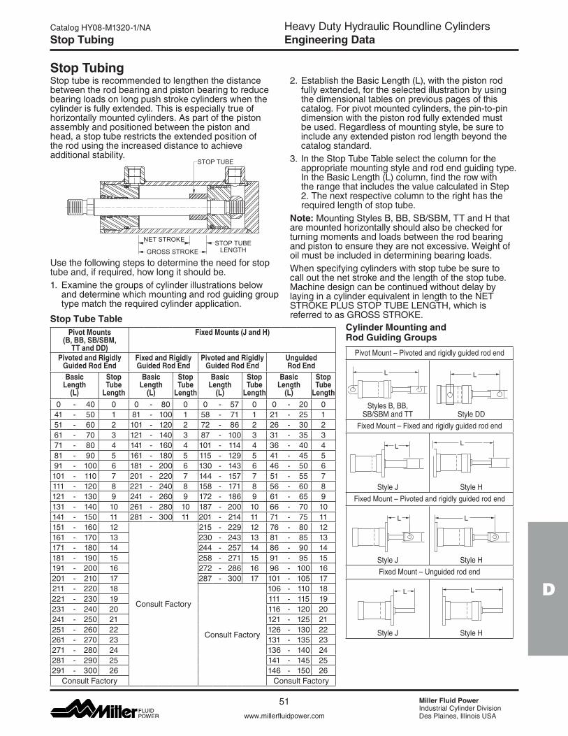
Heavy Duty Hydraulic Roundline CylindersEngineering Data
D
www.millerfluidpower.com
Catalog HY08-M1320-1/NA
51 Miller Fluid PowerIndustrial Cylinder DivisionDes Plaines, Illinois USA
L
Stop Tubing
Stop TubingStop tube is recommended to lengthen the distance between the rod bearing and piston bearing to reduce bearing loads on long push stroke cylinders when the cylinder is fully extended. This is especially true of horizontally mounted cylinders. As part of the piston assembly and positioned between the piston and head, a stop tube restricts the extended position of the rod using the increased distance to achieve additional stability.
Use the following steps to determine the need for stop tube and, if required, how long it should be.1. Examine the groups of cylinder illustrations below
and determine which mounting and rod guiding group type match the required cylinder application.
2. Establish the Basic Length (L), with the piston rod fully extended, for the selected illustration by using the dimensional tables on previous pages of this catalog. For pivot mounted cylinders, the pin-to-pin dimension with the piston rod fully extended must be used. Regardless of mounting style, be sure to include any extended piston rod length beyond the catalog standard.
3. In the Stop Tube Table select the column for the appropriate mounting style and rod end guiding type. In the Basic Length (L) column, find the row with the range that includes the value calculated in Step 2. The next respective column to the right has the required length of stop tube.
Note: Mounting Styles B, BB, SB/SBM, TT and H that are mounted horizontally should also be checked for turning moments and loads between the rod bearing andpistontoensuretheyarenotexcessive.Weightofoil must be included in determining bearing loads.Whenspecifyingcylinderswithstoptubebesuretocall out the net stroke and the length of the stop tube. Machine design can be continued without delay by laying in a cylinder equivalent in length to the NET STROKEPLUSSTOPTUBELENGTH,whichisreferredtoasGROSSSTROKE.
Cylinder Mounting and Rod Guiding GroupsPivotMount–Pivotedandrigidlyguidedrodend
Styles B, BB, SB/SBM and TT Style DD
FixedMount–Fixedandrigidlyguidedrodend
Style J Style HFixedMount–Pivotedandrigidlyguidedrodend
Style J Style HFixedMount–Unguidedrodend
Style J Style H
L
L L
L
L L
Stop Tube Table
L
Pivot Mounts (B, BB, SB/SBM,
TT and DD)
Fixed Mounts (J and H)
Pivoted and Rigidly Guided Rod End
Fixed and Rigidly Guided Rod End
Pivoted and Rigidly Guided Rod End
Unguided Rod End
Basic Length
(L)
Stop Tube
Length
Basic Length
(L)
Stop Tube
Length
Basic Length
(L)
Stop Tube
Length
Basic Length
(L)
Stop Tube
Length0 - 40 0 0 - 80 0 0 - 57 0 0 - 20 041 - 50 1 81 - 100 1 58 - 71 1 21 - 25 151 - 60 2 101 - 120 2 72 - 86 2 26 - 30 261 - 70 3 121 - 140 3 87 - 100 3 31 - 35 371 - 80 4 141 - 160 4 101 - 114 4 36 - 40 481 - 90 5 161 - 180 5 115 - 129 5 41 - 45 591 - 100 6 181 - 200 6 130 - 143 6 46 - 50 6101 - 110 7 201 - 220 7 144 - 157 7 51 - 55 7111 - 120 8 221 - 240 8 158 - 171 8 56 - 60 8121 - 130 9 241 - 260 9 172 - 186 9 61 - 65 9131 - 140 10 261 - 280 10 187 - 200 10 66 - 70 10141 - 150 11 281 - 300 11 201 - 214 11 71 - 75 11151 - 160 12
Consult Factory
215 - 229 12 76 - 80 12161 - 170 13 230 - 243 13 81 - 85 13171 - 180 14 244 - 257 14 86 - 90 14181 - 190 15 258 - 271 15 91 - 95 15191 - 200 16 272 - 286 16 96 - 100 16201 - 210 17 287 - 300 17 101 - 105 17211 - 220 18
Consult Factory
106 - 110 18221 - 230 19 111 - 115 19231 - 240 20 116 - 120 20241 - 250 21 121 - 125 21251 - 260 22 126 - 130 22261 - 270 23 131 - 135 23271 - 280 24 136 - 140 24281 - 290 25 141 - 145 25291 - 300 26 146 - 150 26
Consult Factory Consult Factory
STOP TUBE
GROSS STROKE
NET STROKE STOP TUBELENGTH

Heavy Duty Hydraulic Roundline CylindersEngineering Data
Miller Fluid PowerIndustrial Cylinder DivisionDes Plaines, Illinois USAwww.millerfluidpower.com
Catalog HY08-M1320-1/NA
52
Piston Rod Selection Data
Piston Rod Diameter SelectionTo determine the required rod diameter for a specific stroke, operating pressure, mounting style and rod end guiding condition, use the following steps.1. First, determine whether stop tubing is required as
described on the previous page. 2. Use the Basic Length (L) that was established for
determining the stop tube length and then add the required stop tube length to the Basic Length to obtain an Adjusted Basic Length (LA).
3. In the table below, for the mounting style and rod end guiding condition that will be used, find the row for the Bore and Rod combination that is required.
4. Follow the Bore and Rod row to the right and find the Operating Pressure column that is closest, but exceeds the system pressure. The intersection of the Bore and Rod row and Operating Pressure column displays the maximum allowable LA.
5. If LA in the table is less than the calculated Adjusted Basic Length move down the column to a rod diam-eter with an LA that exceeds the requirement.
6. If the LA specifies a rod diameter in a larger bore then restart the process of sizing the stop tube and re-check the rod diameter. Contact the factory if LA exceeds 300 inches.
Maximum Basic Lengths (LA) (all dimensions in inches)
1 Maximum operating pressure is limited for the SB Mount. Please refer to maximum operating pressure per bore in SB Pressure Ratings table on page 14.
Note: Data in these tables assume standard rod exten-sion(Wdimension)andstandardrodendaccessories.If different, please consult factory.
Bore Ø
Rod Ø
Rear Pivot Mounts (B, BB, SB1, SBM and TT)
Front Fixed Mount (J)
Pivoted and Rigidly Guided Rod End
Fixed and Rigidly Guided Rod End
Pivoted and Rigidly Guided Rod End
Unguided Rod End
Max. Allowable Basic Length (LA) at psi:
Max. Allowable Basic Length (LA) at psi:
Max. Allowable Basic Length (LA) at psi:
Max. Allowable Basic Length (LA) at psi:
500 1000 1500 2000 2500 3000 500 1000 1500 2000 2500 3000 500 1000 1500 2000 2500 3000 500 1000 1500 2000 2500 3000
1.500.625 35 25 20 18 16 14 50 35 29 25 22 20 36 25 21 18 16 15 13 9 7 6 6 51.000 85 60 49 42 38 35 128 91 74 64 57 52 92 65 53 46 41 37 32 23 19 16 14 13
2.001.000 66 47 38 33 29 27 96 68 56 48 43 39 69 49 40 34 31 28 24 17 14 12 11 101.375 116 82 67 58 52 47 182 129 105 91 81 74 130 92 75 65 58 53 45 32 26 23 20 19
2.50 1.000 54 38 31 27 24 22 77 54 44 38 34 31 55 39 32 27 25 22 19 14 11 10 9 81.375 99 70 57 49 44 40 146 103 84 73 65 59 104 73 60 52 46 42 36 26 21 18 16 151.750 151 106 87 75 67 61 236 167 136 118 105 96 168 119 97 84 75 69 59 42 34 29 26 24
3.25 1.375 78 55 45 39 35 32 112 79 65 56 50 46 80 57 46 40 36 33 28 20 16 14 13 111.750 123 87 71 62 55 50 181 128 105 91 81 74 130 92 75 65 58 53 45 32 26 23 20 192.000 157 111 90 78 70 64 237 167 137 118 106 97 169 120 98 85 76 69 59 42 34 30 26 24
4.001.750 102 72 59 51 45 41 147 104 85 74 66 60 105 74 61 53 47 43 37 26 21 18 16 152.000 131 92 75 65 58 53 192 136 111 96 86 79 137 97 79 69 61 56 48 34 28 24 22 202.500 194 137 112 97 87 79 300 213 174 150 134 123 215 152 124 107 96 88 75 53 43 38 34 31
5.00
2.000 107 76 62 53 48 44 154 109 89 77 69 63 110 78 63 55 49 45 38 27 22 19 17 162.500 163 115 94 82 73 67 241 170 139 120 108 98 172 121 99 86 77 70 60 43 35 30 27 253.000 226 160 130 113 101 92 300 245 200 173 155 141 247 175 143 124 111 101 87 61 50 43 39 353.500 289 204 167 145 129 118 300 300 272 236 211 192 300 238 194 168 151 137 118 83 68 59 53 48
6.00
2.500 139 98 80 70 62 57 200 142 116 100 90 82 143 101 83 72 64 58 50 35 29 25 22 203.000 197 139 114 98 88 80 289 204 167 144 129 118 206 146 119 103 92 84 72 51 42 36 32 293.500 260 184 150 130 116 106 300 278 227 196 176 160 281 198 162 140 125 115 98 69 57 49 44 404.000 300 231 188 163 146 133 300 300 296 257 229 209 300 259 212 183 164 150 128 91 74 64 57 52
7.00
3.000 171 121 99 85 76 70 247 175 143 124 111 101 177 125 102 88 79 72 62 44 36 31 28 253.500 228 161 132 114 102 93 300 238 194 168 151 137 241 170 139 120 108 98 84 60 49 42 38 344.000 289 204 167 145 129 118 300 300 254 220 197 180 300 222 181 157 140 128 110 78 63 55 49 454.500 300 249 203 176 157 144 300 300 300 278 249 227 300 281 230 199 178 162 139 98 80 70 62 575.000 300 293 239 207 185 169 300 300 300 300 300 281 300 300 283 245 220 200 172 121 99 86 77 70
8.00
3.500 203 144 117 102 91 83 295 208 170 147 132 120 210 149 122 105 94 86 74 52 43 37 33 304.000 261 185 151 131 117 107 300 272 222 192 172 157 275 194 159 137 123 112 96 68 56 48 43 394.500 300 229 187 162 145 132 300 300 281 244 218 199 300 246 201 174 156 142 122 86 70 61 54 505.000 300 274 224 194 174 158 300 300 300 300 269 245 300 300 248 215 192 175 150 106 87 75 67 615.500 300 300 261 226 202 185 300 300 300 300 300 297 300 300 300 260 232 212 182 129 105 91 81 74
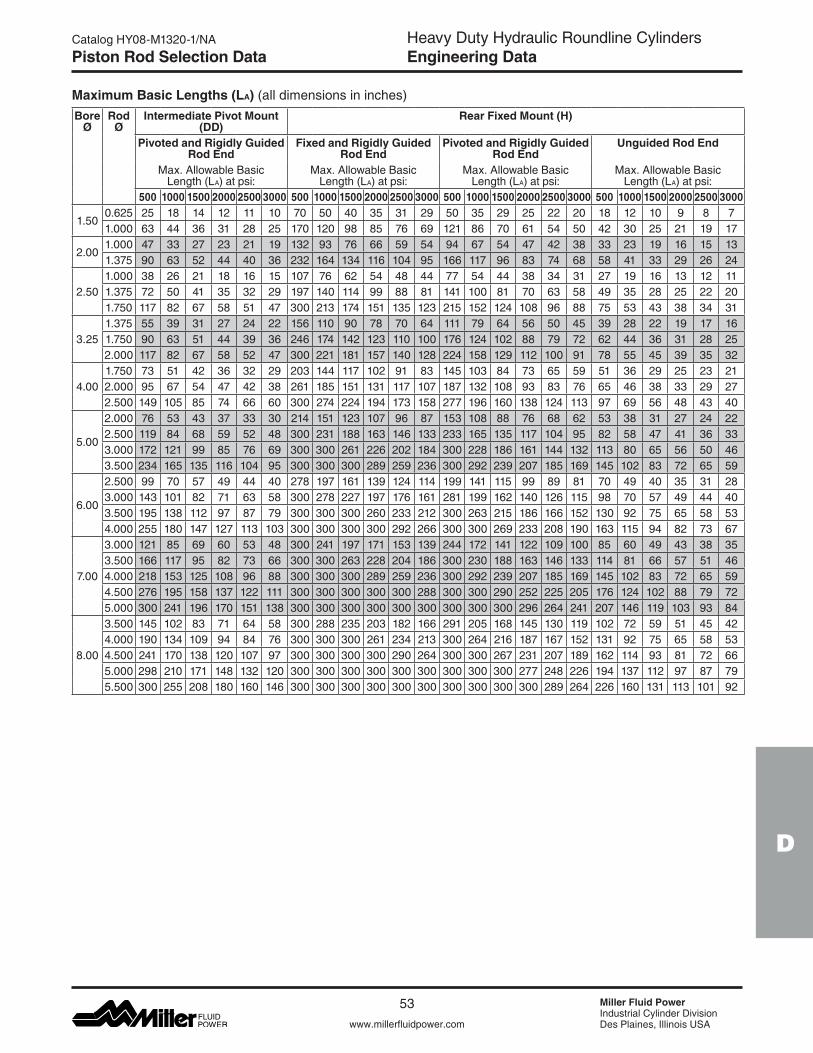
Heavy Duty Hydraulic Roundline CylindersEngineering Data
D
www.millerfluidpower.com
Catalog HY08-M1320-1/NA
53 Miller Fluid PowerIndustrial Cylinder DivisionDes Plaines, Illinois USA
Piston Rod Selection Data
Maximum Basic Lengths (LA) (all dimensions in inches)Bore
ØRod
ØIntermediate Pivot Mount
(DD)Rear Fixed Mount (H)
Pivoted and Rigidly Guided Rod End
Fixed and Rigidly Guided Rod End
Pivoted and Rigidly Guided Rod End
Unguided Rod End
Max. Allowable Basic Length (LA) at psi:
Max. Allowable Basic Length (LA) at psi:
Max. Allowable Basic Length (LA) at psi:
Max. Allowable Basic Length (LA) at psi:
500 1000 1500 2000 2500 3000 500 1000 1500 2000 2500 3000 500 1000 1500 2000 2500 3000 500 1000 1500 2000 2500 3000
1.500.625 25 18 14 12 11 10 70 50 40 35 31 29 50 35 29 25 22 20 18 12 10 9 8 71.000 63 44 36 31 28 25 170 120 98 85 76 69 121 86 70 61 54 50 42 30 25 21 19 17
2.001.000 47 33 27 23 21 19 132 93 76 66 59 54 94 67 54 47 42 38 33 23 19 16 15 131.375 90 63 52 44 40 36 232 164 134 116 104 95 166 117 96 83 74 68 58 41 33 29 26 24
2.501.000 38 26 21 18 16 15 107 76 62 54 48 44 77 54 44 38 34 31 27 19 16 13 12 111.375 72 50 41 35 32 29 197 140 114 99 88 81 141 100 81 70 63 58 49 35 28 25 22 201.750 117 82 67 58 51 47 300 213 174 151 135 123 215 152 124 108 96 88 75 53 43 38 34 31
3.251.375 55 39 31 27 24 22 156 110 90 78 70 64 111 79 64 56 50 45 39 28 22 19 17 161.750 90 63 51 44 39 36 246 174 142 123 110 100 176 124 102 88 79 72 62 44 36 31 28 252.000 117 82 67 58 52 47 300 221 181 157 140 128 224 158 129 112 100 91 78 55 45 39 35 32
4.001.750 73 51 42 36 32 29 203 144 117 102 91 83 145 103 84 73 65 59 51 36 29 25 23 212.000 95 67 54 47 42 38 261 185 151 131 117 107 187 132 108 93 83 76 65 46 38 33 29 272.500 149 105 85 74 66 60 300 274 224 194 173 158 277 196 160 138 124 113 97 69 56 48 43 40
5.00
2.000 76 53 43 37 33 30 214 151 123 107 96 87 153 108 88 76 68 62 53 38 31 27 24 222.500 119 84 68 59 52 48 300 231 188 163 146 133 233 165 135 117 104 95 82 58 47 41 36 333.000 172 121 99 85 76 69 300 300 261 226 202 184 300 228 186 161 144 132 113 80 65 56 50 463.500 234 165 135 116 104 95 300 300 300 289 259 236 300 292 239 207 185 169 145 102 83 72 65 59
6.00
2.500 99 70 57 49 44 40 278 197 161 139 124 114 199 141 115 99 89 81 70 49 40 35 31 283.000 143 101 82 71 63 58 300 278 227 197 176 161 281 199 162 140 126 115 98 70 57 49 44 403.500 195 138 112 97 87 79 300 300 300 260 233 212 300 263 215 186 166 152 130 92 75 65 58 534.000 255 180 147 127 113 103 300 300 300 300 292 266 300 300 269 233 208 190 163 115 94 82 73 67
7.00
3.000 121 85 69 60 53 48 300 241 197 171 153 139 244 172 141 122 109 100 85 60 49 43 38 353.500 166 117 95 82 73 66 300 300 263 228 204 186 300 230 188 163 146 133 114 81 66 57 51 464.000 218 153 125 108 96 88 300 300 300 289 259 236 300 292 239 207 185 169 145 102 83 72 65 594.500 276 195 158 137 122 111 300 300 300 300 300 288 300 300 290 252 225 205 176 124 102 88 79 725.000 300 241 196 170 151 138 300 300 300 300 300 300 300 300 300 296 264 241 207 146 119 103 93 84
8.00
3.500 145 102 83 71 64 58 300 288 235 203 182 166 291 205 168 145 130 119 102 72 59 51 45 424.000 190 134 109 94 84 76 300 300 300 261 234 213 300 264 216 187 167 152 131 92 75 65 58 534.500 241 170 138 120 107 97 300 300 300 300 290 264 300 300 267 231 207 189 162 114 93 81 72 665.000 298 210 171 148 132 120 300 300 300 300 300 300 300 300 300 277 248 226 194 137 112 97 87 795.500 300 255 208 180 160 146 300 300 300 300 300 300 300 300 300 300 289 264 226 160 131 113 101 92
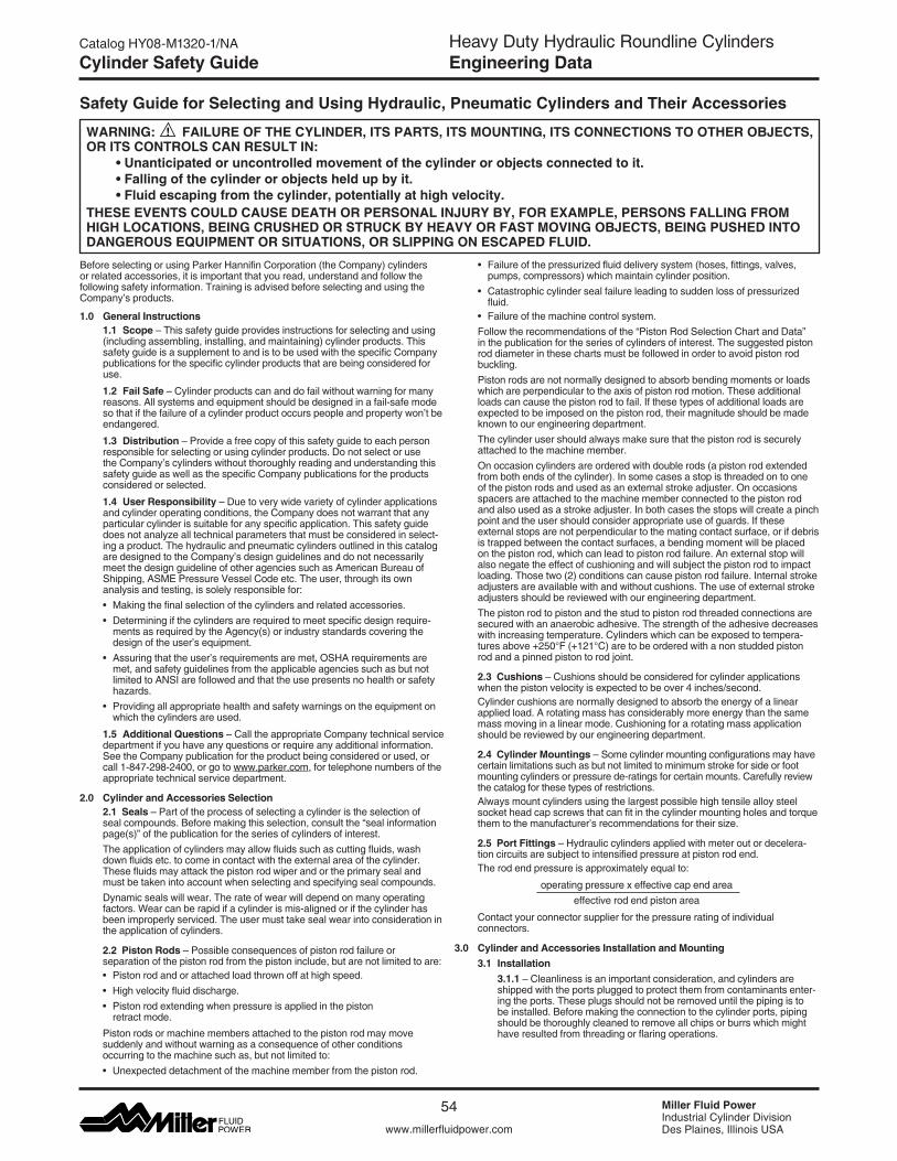
Heavy Duty Hydraulic Roundline CylindersEngineering Data
Miller Fluid PowerIndustrial Cylinder DivisionDes Plaines, Illinois USAwww.millerfluidpower.com
Catalog HY08-M1320-1/NA
54
Cylinder Safety Guide
Before selecting or using Parker Hannifin Corporation (the Company) cylinders or related accessories, it is important that you read, understand and follow the following safety information. Training is advised before selecting and using the Company’s products.
1.0 General Instructions 1.1 Scope–Thissafetyguideprovidesinstructionsforselectingandusing
(including assembling, installing, and maintaining) cylinder products. This safety guide is a supplement to and is to be used with the specific Company publications for the specific cylinder products that are being considered for use.
1.2 Fail Safe–Cylinderproductscananddofailwithoutwarningformanyreasons. All systems and equipment should be designed in a fail-safe mode so that if the failure of a cylinder product occurs people and property won’t be endangered.
1.3 Distribution–Provideafreecopyofthissafetyguidetoeachpersonresponsible for selecting or using cylinder products. Do not select or use the Company’s cylinders without thoroughly reading and understanding this safety guide as well as the specific Company publications for the products considered or selected.
1.4 User Responsibility–Duetoverywidevarietyofcylinderapplicationsand cylinder operating conditions, the Company does not warrant that any particular cylinder is suitable for any specific application. This safety guide does not analyze all technical parameters that must be considered in select-ing a product. The hydraulic and pneumatic cylinders outlined in this catalog are designed to the Company’s design guidelines and do not necessarily meet the design guideline of other agencies such as American Bureau of Shipping,ASMEPressureVesselCodeetc.Theuser,throughitsown analysis and testing, is solely responsible for:
• Makingthefinalselectionofthecylindersandrelatedaccessories. •Determiningifthecylindersarerequiredtomeetspecificdesignrequire-
ments as required by the Agency(s) or industry standards covering the design of the user’s equipment.
•Assuringthattheuser’srequirementsaremet,OSHArequirementsaremet, and safety guidelines from the applicable agencies such as but not limited to ANSI are followed and that the use presents no health or safety hazards.
•Providingallappropriatehealthandsafetywarningsontheequipmentonwhich the cylinders are used.
1.5 Additional Questions–CalltheappropriateCompanytechnicalservicedepartment if you have any questions or require any additional information. See the Company publication for the product being considered or used, or call 1-847-298-2400, or go to www.parker.com, for telephone numbers of the appropriate technical service department.
2.0 Cylinder and Accessories Selection 2.1 Seals–Partoftheprocessofselectingacylinderistheselectionof
seal compounds. Before making this selection, consult the “seal information page(s)” of the publication for the series of cylinders of interest.
The application of cylinders may allow fluids such as cutting fluids, wash down fluids etc. to come in contact with the external area of the cylinder. These fluids may attack the piston rod wiper and or the primary seal and must be taken into account when selecting and specifying seal compounds.
Dynamic seals will wear. The rate of wear will depend on many operating factors.Wearcanberapidifacylinderismis-alignedorifthecylinderhasbeen improperly serviced. The user must take seal wear into consideration in the application of cylinders.
2.2 Piston Rods–Possibleconsequencesofpistonrodfailureor separation of the piston rod from the piston include, but are not limited to are:
•Pistonrodandorattachedloadthrownoffathighspeed. •Highvelocityfluiddischarge. •Pistonrodextendingwhenpressureisappliedinthepiston
retract mode.
Piston rods or machine members attached to the piston rod may move suddenly and without warning as a consequence of other conditions occurring to the machine such as, but not limited to:
•Unexpecteddetachmentofthemachinememberfromthepistonrod.
•Failureofthepressurizedfluiddeliverysystem(hoses,fittings,valves,pumps, compressors) which maintain cylinder position.
•Catastrophiccylindersealfailureleadingtosuddenlossofpressurizedfluid.
•Failureofthemachinecontrolsystem. Follow the recommendations of the “Piston Rod Selection Chart and Data”
in the publication for the series of cylinders of interest. The suggested piston rod diameter in these charts must be followed in order to avoid piston rod buckling.
Piston rods are not normally designed to absorb bending moments or loads which are perpendicular to the axis of piston rod motion. These additional loads can cause the piston rod to fail. If these types of additional loads are expected to be imposed on the piston rod, their magnitude should be made known to our engineering department.
The cylinder user should always make sure that the piston rod is securely attached to the machine member.
On occasion cylinders are ordered with double rods (a piston rod extended from both ends of the cylinder). In some cases a stop is threaded on to one of the piston rods and used as an external stroke adjuster. On occasions spacers are attached to the machine member connected to the piston rod and also used as a stroke adjuster. In both cases the stops will create a pinch point and the user should consider appropriate use of guards. If these external stops are not perpendicular to the mating contact surface, or if debris is trapped between the contact surfaces, a bending moment will be placed on the piston rod, which can lead to piston rod failure. An external stop will also negate the effect of cushioning and will subject the piston rod to impact loading. Those two (2) conditions can cause piston rod failure. Internal stroke adjusters are available with and without cushions. The use of external stroke adjusters should be reviewed with our engineering department.
The piston rod to piston and the stud to piston rod threaded connections are secured with an anaerobic adhesive. The strength of the adhesive decreases with increasing temperature. Cylinders which can be exposed to tempera-turesabove+250°F(+121°C)aretobeorderedwithanonstuddedpistonrod and a pinned piston to rod joint.
2.3 Cushions–Cushionsshouldbeconsideredforcylinderapplicationswhen the piston velocity is expected to be over 4 inches/second.
Cylinder cushions are normally designed to absorb the energy of a linear applied load. A rotating mass has considerably more energy than the same mass moving in a linear mode. Cushioning for a rotating mass application should be reviewed by our engineering department.
2.4 Cylinder Mountings–Somecylindermountingconfigurationsmayhavecertain limitations such as but not limited to minimum stroke for side or foot mounting cylinders or pressure de-ratings for certain mounts. Carefully review the catalog for these types of restrictions.
Always mount cylinders using the largest possible high tensile alloy steel socket head cap screws that can fit in the cylinder mounting holes and torque them to the manufacturer’s recommendations for their size.
2.5 Port Fittings–Hydrauliccylindersappliedwithmeteroutordecelera-tion circuits are subject to intensified pressure at piston rod end.
The rod end pressure is approximately equal to:
operating pressure x effective cap end area effective rod end piston area
Contact your connector supplier for the pressure rating of individual connectors.
3.0 Cylinder and Accessories Installation and Mounting 3.1 Installation 3.1.1 –Cleanlinessisanimportantconsideration,andcylindersare
shipped with the ports plugged to protect them from contaminants enter-ing the ports. These plugs should not be removed until the piping is to be installed. Before making the connection to the cylinder ports, piping should be thoroughly cleaned to remove all chips or burrs which might have resulted from threading or flaring operations.
Safety Guide for Selecting and Using Hydraulic, Pneumatic Cylinders and Their Accessories
WARNING: FAILURE OF THE CYLINDER, ITS PARTS, ITS MOUNTING, ITS CONNECTIONS TO OTHER OBJECTS, OR ITS CONTROLS CAN RESULT IN: •Unanticipatedoruncontrolledmovementofthecylinderorobjectsconnectedtoit. •Fallingofthecylinderorobjectsheldupbyit. •Fluidescapingfromthecylinder,potentiallyathighvelocity.THESE EVENTS COULD CAUSE DEATH OR PERSONAL INJURY BY, FOR EXAMPLE, PERSONS FALLING FROM HIGH LOCATIONS, BEING CRUSHED OR STRUCK BY HEAVY OR FAST MOVING OBJECTS, BEING PUSHED INTO DANGEROUS EQUIPMENT OR SITUATIONS, OR SLIPPING ON ESCAPED FLUID.
Heavy Duty Hydraulic Roundline CylindersEngineering Data
D
www.millerfluidpower.com
Catalog HY08-M1320-1/NA
55 Miller Fluid PowerIndustrial Cylinder DivisionDes Plaines, Illinois USA
Cylinder Safety Guide
3.1.2 –Cylindersoperatinginanenvironmentwhereairdryingmaterialsare present such as fast-drying chemicals, paint, or weld splatter, or other hazardous conditions such as excessive heat, should have shields installed to prevent damage to the piston rod and piston rod seals.
3.1.3 –Properalignmentofthecylinderpistonrodanditsmatingcomponent on the machine should be checked in both the extended and retracted positions. Improper alignment will result in excessive rod gland and/or cylinder bore wear. On fixed mounting cylinders attaching the pis-ton rod while the rod is retracted will help in achieving proper alignment.
3.1.4 –Sometimesitmaybenecessarytorotatethepistonrodinorderto thread the piston rod into the machine member. This operation must always be done with zero pressure being applied to either side of the piston. Failure to follow this procedure may result in loosening the piston to rod-threaded connection. In some rare cases the turning of the piston rod may rotate a threaded head and loosen it from the cylinder body. Confirm that this condition is not occurring. If it does, re-tighten the head firmly against the cylinder body.
For double rod cylinders it is also important that when attaching or detaching the piston rod from the machine member that the torque be applied to the piston rod end of the cylinder that is directly attaching to the machine member with the opposite end unrestrained. If the design of the machine is such that only the rod end of the cylinder opposite to where the rod attaches to the machine member can be rotated, consult the factory for further instructions.
3.2 Mounting Recommendations 3.2.1 –Alwaysmountcylindersusingthelargestpossiblehightensile
alloy steel socket head screws that can fit in the cylinder mounting holes and torque them to the manufacturer’s recommendations for their size.
3.2.2 –Side-MountedCylinders–Inadditiontothemountingbolts,cylinders of this type should be equipped with thrust keys or dowel pins located so as to resist the major load.
3.2.3 –TieRodMounting–Cylinderswithtierodmountingsarerecom-mended for applications where mounting space is limited. Nuts used for this mounting style should be torqued to the same value as the tie rods for that bore size.
3.2.4 –FlangeMountCylinders–Thecontrolleddiameteroftherodgland extension on head end flange mount cylinders can be used as a pilot to locate the cylinders in relation to the machine. After align-ment has been obtained, the flanges may be drilled for pins or dowels to prevent shifting.
3.2.5 –TrunnionMountings–Cylindersrequirelubricatedbearingblockswith minimum bearing clearances. Bearing blocks should be carefully aligned and rigidly mounted so the trunnions will not be subjected to bending moments. The rod end should also be pivoted with the pivot pin in line and parallel to axis of the trunnion pins.
3.2.6 –ClevisMountings–Cylindersshouldbepivotedatbothendswith centerline of pins parallel to each other. After cylinder is mounted, be sure to check to assure that the cylinder is free to swing through its working arc without interference from other machine parts.
4.0 Cylinder and Accessories Maintenance, Troubleshooting and Replacement
4.1 Storage–Attimescylindersaredeliveredbeforeacustomerisreadytoinstallthemandmustbestoredforaperiodoftime.Whenstorageisrequiredthe following procedures are recommended.
4.1.1 –Storethecylindersinanindoorareawhichhasadry,cleanandnoncorrosive atmosphere. Take care to protect the cylinder from both internal corrosion and external damage.
4.1.2 –Wheneverpossiblecylindersshouldbestoredinaverticalposi-tion (piston rod up). This will minimize corrosion due to possible conden-sation which could occur inside the cylinder. This will also minimize seal damage.
4.1.3 –Portprotectorplugsshouldbeleftinthecylinderuntilthetimeofinstallation.
4.1.4 –Ifacylinderisstoredfullofhydraulicfluid,expansionofthefluiddue to temperature changes must be considered. Installing a check valve with free flow out of the cylinder is one method.
4.1.5 –Whencylindersaremountedonequipmentthatisstoredoutsidefor extended periods, exposed unpainted surfaces, e.g. piston rod, must be coated with a rust-inhibiting compound to prevent corrosion.
4.2 Cylinder Trouble Shooting
4.2.1 –External Leakage 4.2.1.1 –Rodsealleakagecangenerallybetracedtowornor
damaged seals. Examine the piston rod for dents, gouges or score marks, and replace piston rod if surface is rough.
Rod seal leakage could also be traced to bearing wear. If clear-ance is excessive, replace rod bearing and seal. Rod seal leakage can also be traced to seal deterioration. If seals are soft or gummy or brittle, check compatibility of seal material with lubricant used if air cylinder, or operating fluid if hydraulic cylinder. Replace with seal material, which is compatible with these fluids. If the seals are hard or have lost elasticity, it is usually due to exposure to tem-peraturesinexcessof165°F.(+74°C).Shieldthecylinderfromtheheatsourcetolimittemperatureto350°F.(+177°C.)andreplacewith fluorocarbon seals.
4.2.1.2 –Cylinderbodysealleakcangenerallybetracedtoaloose head. Torque the head to manufacturer’s recommendation for that bore size.
Excessive pressure can also result in cylinder body seal leak. Determine maximum pressure to rated limits. Replace seals and retorque head as in paragraph above. Excessive pressure can also result in cylinder body seal leak. Determine if the pressure rating of the cylinder has been exceeded. If so, bring the operating pressure down to the rating of the cylinder and have the head replaced.
Pinched or extruded cylinder body seal will also result in a leak. Replace cylinder body seal and retorque as in paragraph above.
Cylinder body seal leakage due to loss of radial squeeze which shows up in the form of flat spots or due to wear on the O.D. or I.D. –Eitherofthesearesymptomsofnormalwearduetohighcyclerate or length of service. Replace seals as per paragraph above.
4.2.2 –Internal Leakage 4.2.2.1 –Pistonsealleak(by-pass)1to3cubicinchesperminute
leakageisconsiderednormalforpistonringconstruction.Virtuallyno static leak with lipseal type seals on piston should be expected. Piston seal wear is a usual cause of piston seal leakage. Replace seals as required.
4.2.2.2 –Withlipsealtypepistonsealsexcessivebackpressuredue to over-adjustment of speed control valves could be a direct cause of rapid seal wear. Contamination in a hydraulic system can result in a scored cylinder bore, resulting in rapid seal wear. In either case, replace piston seals as required.
4.2.2.3 –Whatappearstobepistonsealleak,evidencedbythefact that the cylinder drifts, is not always traceable to the piston. To make sure, it is suggested that one side of the cylinder piston be pressurized and the fluid line at the opposite port be disconnected. Observe leakage. If none is evident, seek the cause of cylinder drift in other component parts in the circuit.
4.2.3 –Cylinder Fails to Move the Load 4.2.3.1 –Pneumaticorhydraulicpressureistoolow.Checkthe
pressure at the cylinder to make sure it is to circuit requirements. 4.2.3.2 –PistonSealLeak–Operatethevalvetocyclethecylinder
and observe fluid flow at valve exhaust ports at end of cylinder stroke. Replace piston seals if flow is excessive.
4.2.3.3 –Cylinderisundersizedfortheload–Replacecylinderwithone of a larger bore size.
4.3 Erratic or Chatter Operation 4.3.1 –Excessivefrictionatrodbearingorpistonbearingduetoload
misalignment–Correctcylinder-to-loadalignment. 4.3.2 –Cylindersizedtooclosetoloadrequirements–Reduceloador
install larger cylinder. 4.3.3 –Erraticoperationcouldbetracedtothedifferencebetweenstatic
and kinetic friction. Install speed control valves to provide a back pres-sure to control the stroke.
4.4 Cylinder Modifications, Repairs, or Failed Component–Cylinders as shipped from the factory are not to be disassembled and or modified. If cylinders require modifications, these modifications must be done at company locations or by the Company’s certified facilities. The Industrial Cylinder Division Engineering Department must be notified in the event of a mechanical fracture or permanent deformation of any cylinder component (excluding seals). This includes a broken piston rod, head, mounting accessory or any other cylinder component. The notification should include all operation and application details. This information will be used to provide an engineered repair that will prevent recurrence of the failure.
It is allowed to disassemble cylinders for the purpose of replacing seals or seal assemblies. However, this work must be done by strictly following all the instructions provided with the seal kits.
Heavy Duty Hydraulic Roundline CylindersSeries RDH
Miller Fluid PowerIndustrial Cylinder DivisionDes Plaines, Illinois USAwww.millerfluidpower.com
Catalog HY08-M1320-1/NA
56
Offer of Sale
TheitemsdescribedinthisdocumentandotherdocumentsanddescriptionsprovidedbyParkerHannifinCorporation,HydraulicsGroup,anditsauthorizeddistributors(“Seller”)arehereby offered for sale at prices to be established by Seller. This offer and its acceptance by any customer (“Buyer”) shall be governed by all of the following Terms and Conditions. Buyer’s order for any item described in its document, when communicated to Seller verbally, or in writing, shall constitute acceptance of this offer. All goods or work described will be referred to as “Products”.1. Terms and Conditions. Seller’s willingness to offer Products, or accept an order for Products, to or from Buyer is expressly conditioned on Buyer’s assent to these Terms and Conditions and to the terms and conditions found on-line at www.parker.com/saleterms/. Seller objects to any contrary or additional term or condition of Buyer’s order or any other document issued by Buyer.2. Price Adjustments; Payments. Prices stated on the reverse side or preceding pages of this document are valid for 30 days. After 30 days, Seller may change prices to reflect any increase in its costs resulting from state, federal or local legislation, price increases from its suppliers, or any change in the rate, charge, or classification of any carrier. The prices stated on the reverse or preceding pages of this document do not include any sales, use, or other taxes unless so stated specifically. Unless otherwise specified by Seller, all prices are F.O.B. Seller’s facility, and payment is due 30 days from the date of invoice. After 30 days, Buyer shall pay interest on any unpaid invoices at the rate of 1.5% per month or the maximum allowable rate under applicable law.3. Delivery Dates; Title and Risk; Shipment. All delivery dates are approximate and Seller shall not be responsible for any damages resulting from any delay. Regardless of the manner of shipment, title to any products and risk of loss or damage shall pass to Buyer upon tender to the carrier at Seller’s facility (i.e., when it’s on the truck, it’s yours). Unless otherwise stated, Seller may exercise its judgment in choosing the carrier and means of delivery. No deferment of shipment at Buyers’ request beyond the respective dates indicated will be made except on terms that will indemnify, defend and hold Seller harmless against all loss and additional expense. Buyer shall be responsible for any additional shipping charges incurred by Seller due to Buyer’s changes in shipping, product specifications or in accordance with Section 13, herein.4. Warranty. Seller warrants that the Products sold hereunder shall be free from defects in material or workmanship for a period of eighteen months from the date of delivery to Buyer. The prices charged for Seller’s products are based upon the exclusive limited warranty stated above, and upon the following disclaimer: DISCLAIMER OFWARRANTY: THISWARRANTY COMPRISES THE SOLE AND ENTIRE WARRANTY PERTAINING TO PRODUCTS PROVIDED HEREUNDER. SELLER DISCLAIMS ALL OTHER WARRANTIES, EXPRESS AND IMPLIED, INCLUDINGMERCHANTABILITYANDFITNESSFORAPARTICULARPURPOSE.5. Claims; Commencement of Actions. Buyer shall promptly inspect all Products upon delivery. No claims for shortages will be allowed unless reported to the Seller within 10 days of delivery. No other claims against Seller will be allowed unless asserted in writing within 60 days after delivery or, in the case of an alleged breach of warranty, within 30 days after the date within the warranty period on which the defect is or should have been discovered by Buyer. Any action based upon breach of this agreement or upon any other claim arising out of this sale (other than an action by Seller for any amount due to Seller from Buyer) must be commenced within thirteen months from the date of tender of delivery by Seller or, for a cause of action based upon an alleged breach of warranty, within thirteen months from the date within the warranty period on which the defect is or should have been discovered by Buyer.6. LIMITATION OF LIABILITY. UPON NOTIFICATION, SELLER WILL, AT ITS OPTION, REPAIR OR REPLACE A DEFECTIVE PRODUCT, OR REFUND THE PURCHASEPRICE. INNOEVENTSHALLSELLERBE LIABLE TOBUYERFORANYSPECIAL,INDIRECT,INCIDENTALORCONSEQUENTIALDAMAGESARISING OUT OF, OR AS THE RESULT OF, THE SALE, DELIVERY, NON-DELIVERY, SERVICING,USEORLOSSOFUSEOFTHEPRODUCTSORANYPARTTHEREOF, ORFORANYCHARGESOREXPENSESOFANYNATUREINCURREDWITHOUT SELLER’S WRITTEN CONSENT, EVEN IF SELLER HAS BEEN NEGLIGENT,WHETHER IN CONTRACT, TORT OR OTHER LEGAL THEORY. IN NO EVENTSHALL SELLER’S LIABILITY UNDER ANY CLAIM MADE BY BUYER EXCEED THE PURCHASE PRICE OF THE PRODUCTS.7. Contingencies. Seller shall not be liable for any default or delay in performance if caused by circumstances beyond the reasonable control of Seller.8. User Responsibility. The user, through its own analysis and testing, is solely responsible for making the final selection of the system and Product and assuring that all performance, endurance, maintenance, safety and warning requirements of the application are met. The user must analyze all aspects of the application and follow applicable industry standards and Product information. If Seller provides Product or system options, the user is responsible for determining that such data and specifications are suitable and sufficient for all applications and reasonably foreseeable uses of the Products or systems.9. Loss to Buyer’s Property. Any designs, tools, patterns, materials, drawings, confi-dential information or equipment furnished by Buyer or any other items which become Buyer’s property, may be considered obsolete and may be destroyed by Seller after two consecutive years have elapsed without Buyer placing an order for the items which are manufactured using such property. Seller shall not be responsible for any loss or damage to such property while it is in Seller’s possession or control.10. Special Tooling. A tooling charge may be imposed for any special tooling, including without limitation, dies, fixtures, molds and patterns, acquired to manufacture Products. Such special tooling shall be and remain Seller’s property notwithstanding payment of any charges by Buyer. In no event will Buyer acquire any interest in apparatus belonging to Seller which is utilized in the manufacture of the Products, even if such apparatus has been specially converted or adapted for such manufacture and notwithstanding any charges paid by Buyer. Unless otherwise agreed, Seller shall have the right to alter, discard or otherwise dispose of any special tooling or other property in its sole discretion at any time.
11. Buyer’s Obligation; Rights of Seller. To secure payment of all sums due or other-wise, Seller shall retain a security interest in the goods delivered and this agreement shall be deemed a Security Agreement under the Uniform Commercial Code. Buyer authorizes Seller as its attorney to execute and file on Buyer’s behalf all documents Seller deems necessary to perfect its security interest. Seller shall have a security interest in, and lien upon, any property of Buyer in Seller’s possession as security for the payment of any amounts owed to Seller by Buyer.12. Improper Use and Indemnity. Buyer shall indemnify, defend, and hold Seller harmless from any claim, liability, damages, lawsuits, and costs (including attorney fees), whether for personal injury, property damage, patent, trademark or copyright infringement or any other claim, brought by or incurred by Buyer, Buyer’s employees, or any other person, arising out of: (a) improper selection, improper application or other misuse of Products purchased by Buyer from Seller; (b) any act or omission, negligent or otherwise, of Buyer; (c) Seller’s use of patterns, plans, drawings, or specifications furnished by Buyer to manufacture Product; or (d) Buyer’s failure to comply with these terms and conditions. Seller shall not indemnify Buyer under any circumstance except as otherwise provided.13. Cancellations and Changes. Orders shall not be subject to cancellation or change by Buyer for any reason, except with Seller’s written consent and upon terms that will indemnify, defend and hold Seller harmless against all direct, incidental and consequen-tial loss or damage. Seller may change product features, specifications, designs and availability with notice to Buyer.14. Limitation on Assignment. Buyer may not assign its rights or obligations under this agreement without the prior written consent of Seller.15. Entire Agreement. This agreement contains the entire agreement between the Buyer and Seller and constitutes the final, complete and exclusive expression of the terms of the agreement. All prior or contemporaneous written or oral agreements or negotiations with respect to the subject matter are herein merged. 16. Waiver and Severability. Failure to enforce any provision of this agreement will not waive that provision nor will any such failure prejudice Seller’s right to enforce that provision in the future. Invalidation of any provision of this agreement by legislation or other rule of law shall not invalidate any other provision herein. The remaining provisions of this agreement will remain in full force and effect.17. Termination. This agreement may be terminated by Seller for any reason and at any time by giving Buyer thirty (30) days written notice of termination. In addition, Seller may by written notice immediately terminate this agreement for the following: (a) Buyer commits a breach of any provision of this agreement (b) the appointment of a trustee, receiver or custodian for all or any part of Buyer’s property (c) the filing of a petition for relief in bankruptcy of the other Party on its own behalf, or by a third party (d) an assign-ment for the benefit of creditors, or (e) the dissolution or liquidation of the Buyer.18. Governing Law. This agreement and the sale and delivery of all Products here-under shall be deemed to have taken place in and shall be governed and construed in accordance with the laws of the State of Ohio, as applicable to contracts executed and wholly performed therein and without regard to conflicts of laws principles. Buyer irrevocably agrees and consents to the exclusive jurisdiction and venue of the courts of Cuyahoga County, Ohio with respect to any dispute, controversy or claim arising out of or relating to this agreement. Disputes between the parties shall not be settled by arbitration unless, after a dispute has arisen, both parties expressly agree in writing to arbitrate the dispute. 19. Indemnity for Infringement of Intellectual Property Rights. Seller shall have no liability for infringement of any patents, trademarks, copyrights, trade dress, trade secrets or similar rights except as provided in this Section. Seller will defend and indemnify Buyer against allegations of infringement of U.S. patents, U.S. trademarks, copyrights, trade dress and trade secrets (“Intellectual Property Rights”). Seller will defend at its expense and will pay the cost of any settlement or damages awarded in an action brought against Buyer based on an allegation that a Product sold pursuant to this Agreement infringes the Intellectual Property Rights of a third party. Seller’s obligation to defend and indemnify Buyer is contingent on Buyer notifying Seller within ten (10) days after Buyer becomes aware of such allegations of infringement, and Seller having sole control over the defense of any allegations or actions including all negotiations for settle-ment or compromise. If a Product is subject to a claim that it infringes the Intellectual Property Rights of a third party, Seller may, at its sole expense and option, procure for Buyer the right to continue using the Product, replace or modify the Product so as to make it noninfringing, or offer to accept return of the Product and return the purchase price less a reasonable allowance for depreciation. Notwithstanding the foregoing, Seller shall have no liability for claims of infringement based on information provided by Buyer, or directed to Products delivered hereunder for which the designs are specified in whole or part by Buyer, or infringements resulting from the modification, combination or use in a system of any Product sold hereunder. The foregoing provisions of this Section shall constitute Seller’s sole and exclusive liability and Buyer’s sole and exclusive remedy for infringement of Intellectual Property Rights.20. Taxes. Unless otherwise indicated, all prices and charges are exclusive of excise, sales, use, property, occupational or like taxes which may be imposed by any taxing authority upon the manufacture, sale or delivery of Products.21. Equal Opportunity Clause. For the performance of government contracts and where dollar value of the Products exceed $10,000, the equal employment opportunity clausesinExecutiveOrder11246,VEVRAA,and41C.F.R.§§60-1.4(a),60-741.5(a),and 60-250.4, are hereby incorporated.
Offer of Sale


03/11 / Catalog HY08-M1320-1/NA
Parker Hannifin CorporationMiller Fluid Power500SouthWolfRoadDes Plaines, IL 60016 USAphone (847) 298-2400fax (800) 892-1008www.millerfluidpower.com
Parker Hannifin Corporation Motion and Control Division160 Chisholm Drive Milton, ON Canada L9T 3G9 direct (905) 693-3000 fax (905) 876-1958 www.parker.com