Heating and Cooling with Focus on Increased Energy Efficiency and ...
35
1 Heating and Cooling with Focus on Increased Energy Efficiency and Improved Comfort Low Exergy Systems for Heating and Cooling of Buildings Abstract: Environment problems such as global warming, which have been linked to the extended use of energy, and the negative environmental effects of energy production which they are mainly due to the use of fossil fuels. Heating, cooling and lighting appliances in buildings cause more than one third of the world’s primary energy demand. Then using renewable energy sources for heating and cooling buildings is very important for safe future energy demand .Increasing energy efficiency and improving thermal comfort can realize by using low exergy systems for heating and cooling of buildings. ‘Low exergy systems’ means systems that provide heating or cooling energy at a temperature close to room temperature. Low temperature heating systems or high temperature cooling systems can use a variety of fuels and renewable energy sources, having many benefits such as: improved thermal comfort, improved indoor air quality, reduced energy consumption and reduced draughts and dust. Active and passive systems: Passive systems defined as building envelope systems use various environment potentials as sun, wind. Active systems are consisting of various mechanical and electric components as fans, heat pumps… Energy, Exergy, and Entropy: In the theory of thermodynamics, Exergy is the maximum work that can be obtains from an energy flow or a change of a system. Exergy analysis provides us with additional information on where and when the losses occur. It helps us to see in which part of the energy chain the biggest savings can be achieve. While “entropy” is the concept that quantifies how much energy and matter dispersed. EXERGY BALANCE: The amounts of energy flowing in and out of the building are the same under thermally steady-state condition according to the law of energy conservation; on the other hand, the amount of entropy flowing out is larger than flowing in according to the law of entropy increase. The amount of exergy flowing out is smaller than flowing in, since exergy consumed within the system to produce entropy. Exergy balance equations: E in = E st + E out (1.1) ; ( Energy input E in, Energy stored E st , Energy output E out ). E in = E out (1.2) ; ( because it is steady-state condition E st =0 ) I in + I g = I st + I out (1.3) ; (Entropy input I in , Entropy generated I g, Entropy stored I st , Entropy output I out ) . I in + I g = I out (1.4) ; ( because it is steady-state condition I st =0 ) I in x Te + I g xTe = I out x Te (1.5) ; ( Te is the environmental temperature ) The product of entropy and environmental temperature called “anergy”, A in + A g = A out (1.6) ; “A g ” is such energy had an ability to disperse. (E in – A in ) – A g = (E out –A out ) (1.7) Anergy generation is equivalent to exergy consumption. By using the term “exergy”, the above equation can be as following: (Ex in ) – (Ex c ) =(Ex out ) (1.8) (exergy input Ex in, exergy consumed Ex c, exergy output Ex out ). This is the exergy balance equation for a system under steady-state condition such as the building envelope system Ex c = A g = Te x I g (1.9)
Transcript of Heating and Cooling with Focus on Increased Energy Efficiency and ...

1
Heating and Cooling with Focus on Increased Energy Efficiency and Improved Comfort Low Exergy Systems for Heating and Cooling of Buildings Abstract: Environment problems such as global warming, which have been linked to the extended use of energy, and the negative environmental effects of energy production which they are mainly due to the use of fossil fuels. Heating, cooling and lighting appliances in buildings cause more than one third of the world’s primary energy demand. Then using renewable energy sources for heating and cooling buildings is very important for safe future energy demand .Increasing energy efficiency and improving thermal comfort can realize by using low exergy systems for heating and cooling of buildings. ‘Low exergy systems’ means systems that provide heating or cooling energy at a temperature close to room temperature. Low temperature heating systems or high temperature cooling systems can use a variety of fuels and renewable energy sources, having many benefits such as: improved thermal comfort, improved indoor air quality, reduced energy consumption and reduced draughts and dust. Active and passive systems: Passive systems defined as building envelope systems use various environment potentials as sun, wind. Active systems are consisting of various mechanical and electric components as fans, heat pumps… Energy, Exergy, and Entropy: In the theory of thermodynamics, Exergy is the maximum work that can be obtains from an energy flow or a change of a system. Exergy analysis provides us with additional information on where and when the losses occur. It helps us to see in which part of the energy chain the biggest savings can be achieve. While “entropy” is the concept that quantifies how much energy and matter dispersed. EXERGY BALANCE: The amounts of energy flowing in and out of the building are the same under thermally steady-state condition according to the law of energy conservation; on the other hand, the amount of entropy flowing out is larger than flowing in according to the law of entropy increase. The amount of exergy flowing out is smaller than flowing in, since exergy consumed within the system to produce entropy. Exergy balance equations: Ein = Est + Eout (1.1) ; ( Energy input Ein, Energy stored Est, Energy output Eout). Ein = Eout (1.2) ; ( because it is steady-state condition Est =0 ) Iin + Ig = Ist + Iout (1.3) ; (Entropy input Iin, Entropy generated Ig, Entropy stored Ist, Entropy output Iout). Iin + Ig = Iout (1.4) ; ( because it is steady-state condition Ist =0) Iin x Te + Ig xTe = Iout x Te (1.5) ; ( Te is the environmental temperature ) The product of entropy and environmental temperature called “anergy”, Ain + Ag = Aout (1.6) ; “Ag” is such energy had an ability to disperse. (Ein – Ain) – Ag = (Eout –Aout ) (1.7) Anergy generation is equivalent to exergy consumption. By using the term “exergy”, the above equation can be as following: (Exin) – (Exc) =(Exout) (1.8) (exergy input Exin, exergy consumed Exc, exergy output Exout). This is the exergy balance equation for a system under steady-state condition such as the building envelope system Exc = Ag = Te x Ig (1.9)

2
WARM AND COOL EXERGY: Room air has “warm” exergy If its temperature is higher than the outdoor environment. On the other hand, room air has “cool” exergy when its temperature is lower than the outdoor environment. Thermal exergy, whether it is warm exergy or cool exergy, flows through walls, by a combination of convection, conduction, and radiation. -For heat pump, as an example of cooling exergy figure shows that exergy balance equation of the heat pump is given as the following: (Exergy input to the motor and two fans) – (Exergy Consumed) = (Cool Exergy supplied to the room space) + (Warm exergy given off to the ambient air). -The General form of exergy balance equation of a system is: Exergy Input – Exergy Consumed = Exergy Stored + Exergy Output. Human body exergy consumption: -The lowest human body exergy consumption occurs at thermally neutral condition. Exergy consumption within the human body becomes higher in a cold environment due to larger difference in temperature between the human body and its surrounding space and becomes higher in a hot environment mainly due to sweating. Figure shows the relationship between the rates of exergy input, consumed and stored within the human body and the exergy output from the human body and the environmental temperature .The dotted lines represent a case of no shivering in cold condition or no sweating in hot conditions. -There is an optimal combination of room air and mean radiant temperatures, which results in the lowest exergy consumption, and thermal comfort, figure shows the relationship between exergy consumption within the human body (W/m2), room air temperature, and mean radiant temperature. The solid line descending from the upper left corner to the lower right corner indicates thermally neutral conditions (PMV*=0) balance. The broken line in the upper right corner is skin wetness up to the tolerable amount (W = 0.25). This suggests that the use of radiant warm exergy is more effective than the use of convective warm exergy for a heating purpose to realize both thermal comfort and low exergy consumption within the human body. So good thermal insulation, suitable thermal exergy storage capacity of building envelopes and solar thermal exergy gain through insulated window glazing provide possibility to create comfortable built environment. - Exergy consumed can divide to tow parts one for mechanical work and another for temperature drop in the system. -The figure shows the energy flow and losses from the source to the sink, the greatest losses occur at primary energy and heat generation components.

3
Well-insulated building, tight envelopes, sufficient window shading will decrease the energy(exergy) losses and make the energy use more efficient. By using thermal storage and solar gain in h/c building, a minimum of energy at a very low level of temperature difference between the system and the room should be used for thermal conditioning , in this way a maximum of high quality energy (exergy) could be saved. S. SURFACE HEATING AND COOLING S.1 FLOOR HEATING S.1.1 EMBEDDED COILS IN SLABS: Plastic pipes situated in the centre of slab used for heating and cooling spaces, water is the heat-carrying, the concrete slab acts as a Storage-medium, and just low temperature difference is needed to deliver a certain heating and cooling power to the room, so it is self regulating, but its responds is slowly towards temperature changes in both room and supply water because its big capacity. In such system the minimum cooling temperature decided depending on the dew-point of indoor air because if surface relative humidity above 80 % it can causes mould growth. S.1.2 COILS IN SURFACE LAYERS: Coils for heating and cooling can be apply to floors or ceilings and have fast regulation and short response time towards changes in temperature. There are three mainly types available in markets: 1-Solid masonry elements with factory made grooves in the surface, which will form a pattern where the water coils can be mounted before the plastering is applied on the surface, this type is mostly used for walls. 2- Sheet metal profiles that are apply on frame structure and act as heat distributors and load bearing elements for the surface layer. 3) Pre-cut blocks of rigid insulation with grooves for the coil and a conductive metallic foil covering the surface and the inside of the grooves. Apply heating or cooling coils have many surface specifications: 1- Minimum additional thickness to the construction. 2- Minimum heat loss to the under lying construction. 3- Minimum thermal inertia and fast response time. For cooling aim the minimum cooling temperature should taken into account to prevent mould growth S.1.3 HOLLOW CORE SLABS: Ventilation and space conditioning can be realize with one system, the ambient air is preheated or cooled and then circulated in the hollow core construction before released into the room, no draught and low noise air supply to the rooms, not used cores can be used for electrical wiring or other purposes. Because hollow core slabs can span up to18 meters and thus cover more than one room, then the ceiling and floor become like mass storage of energy with wide surfaces for cooling and heating, so thermal stability

4
realize and thermal comfort is increase. Since the air supply is realizing via the ducts, the system has to be clean from time to time, otherwise health problems could arise. S.1.4 SUSPENDED FLOORS: A space below the floor surface layer can be use for multiple purposes: - Heating and cooling air, which will be circulate in the space. - Distribute air to the space above or below, this combination can be overcoming the problems that higher temperature levels of air heating or floor heating alone will create. - As an installation space. With suspended floors thermal comfort is increased because of an even temperature distribution on the floor surfaces and thus relative humidity of the floor construction can be controlled at a low level, no radiators needed, saving space in the living zone for other purposes. However, good thermal insulation is mandatory to prevent unnecessary heat losses to the ground. S.1.5 PHASE CHANGE IN FLOOR HEATING (PCM) (WET AND DRY SYSTEMS): PCMs are used to store energy by the use of latent heat, and change from solid to liquid, they have high storage capacity compared to the low volume which is needed. PCMs divided in two groups: - organic materials (System B): have a higher latent and sensible heat capacity. - inorganic materials (System A) :have a higher density and a better thermal conductivity, usually cheaper than the organic materials. Some disadvantages, such as evaporation, corrosion, separation and changes in volume are solved by macro capsules. On other hand, it is not possible to change System A the storage capacity afterwards. The storage capacity has a large influence on the control of the system. Finally, overheating can be a problem, as the system keeps a lot of heat inside. It need less space because energy storage is integrated into floor. On other hand solar energy, off-peak electricity, heat pump and waste heat are suitable sources to charge the PCM. In general, the thermal comfort of floor heating systems is better than System B conventional radiators or convectors. S.2 WALL HEATING AND COOLING S.2.1 PIPES IN SURFACE LAYERS (WET AND HALF WET SYSTEMS, MOUNTED ON WALLS): The tubes mounted directly on the wall by tow means; copper tubes 16 – 20mm or grid of very thin tubes 2 mm. Users are very satisfied because of equal distribution of heat, and usually set the thermostat at a lower air temperature than for traditional system to obtain an equal thermal comfort sensation. These systems have many advantages such as thermal comfort, indoor air quality (no dust) and no visible radiators. However, there is high risk for damage through user impact, nails, screws etc. S.2.2 PIPES IN SURFACE LAYERS (HALF-DRY SYSTEMS, EMBEDDED IN WALLS): Wall heating – heavy construction in an equal distribution of heat. Occupants are very satisfied especially with indoor air quality (no dust) and no visible radiators, they usually set the thermostat at a lower air temperature than for a traditional system to obtain an equal thermal comfort sensation. But the heating up time of wall heating
5
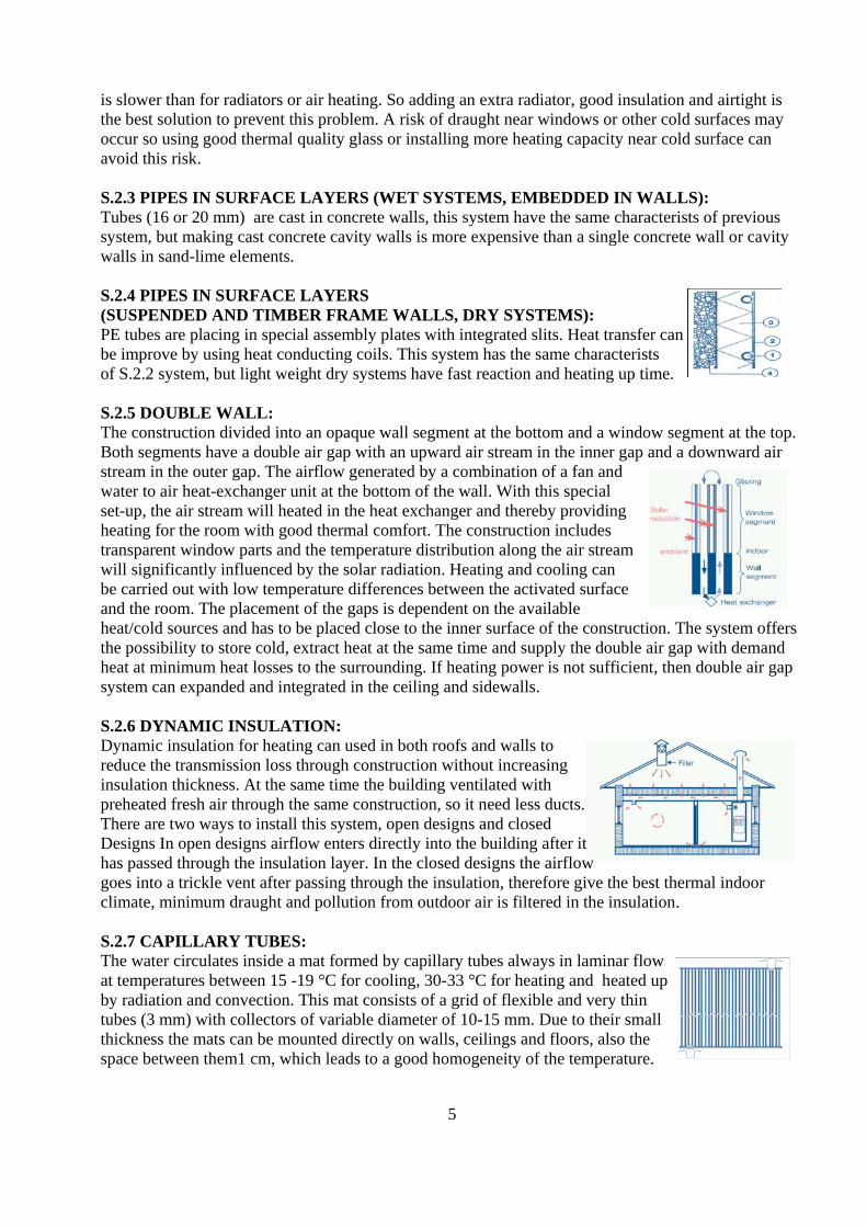
is slower than for radiators or air heating. So adding an extra radiator, good insulation and airtight is the best solution to prevent this problem. A risk of draught near windows or other cold surfaces may occur so using good thermal quality glass or installing more heating capacity near cold surface can avoid this risk. S.2.3 PIPES IN SURFACE LAYERS (WET SYSTEMS, EMBEDDED IN WALLS): Tubes (16 or 20 mm) are cast in concrete walls, this system have the same characterists of previous system, but making cast concrete cavity walls is more expensive than a single concrete wall or cavity walls in sand-lime elements. S.2.4 PIPES IN SURFACE LAYERS (SUSPENDED AND TIMBER FRAME WALLS, DRY SYSTEMS): PE tubes are placing in special assembly plates with integrated slits. Heat transfer can be improve by using heat conducting coils. This system has the same characterists of S.2.2 system, but light weight dry systems have fast reaction and heating up time. S.2.5 DOUBLE WALL: The construction divided into an opaque wall segment at the bottom and a window segment at the top. Both segments have a double air gap with an upward air stream in the inner gap and a downward air stream in the outer gap. The airflow generated by a combination of a fan and water to air heat-exchanger unit at the bottom of the wall. With this special set-up, the air stream will heated in the heat exchanger and thereby providing heating for the room with good thermal comfort. The construction includes transparent window parts and the temperature distribution along the air stream will significantly influenced by the solar radiation. Heating and cooling can be carried out with low temperature differences between the activated surface and the room. The placement of the gaps is dependent on the available heat/cold sources and has to be placed close to the inner surface of the construction. The system offers the possibility to store cold, extract heat at the same time and supply the double air gap with demand heat at minimum heat losses to the surrounding. If heating power is not sufficient, then double air gap system can expanded and integrated in the ceiling and sidewalls. S.2.6 DYNAMIC INSULATION: Dynamic insulation for heating can used in both roofs and walls to reduce the transmission loss through construction without increasing insulation thickness. At the same time the building ventilated with preheated fresh air through the same construction, so it need less ducts. There are two ways to install this system, open designs and closed Designs In open designs airflow enters directly into the building after it has passed through the insulation layer. In the closed designs the airflow goes into a trickle vent after passing through the insulation, therefore give the best thermal indoor climate, minimum draught and pollution from outdoor air is filtered in the insulation. S.2.7 CAPILLARY TUBES: The water circulates inside a mat formed by capillary tubes always in laminar flow at temperatures between 15 -19 °C for cooling, 30-33 °C for heating and heated up by radiation and convection. This mat consists of a grid of flexible and very thin tubes (3 mm) with collectors of variable diameter of 10-15 mm. Due to their small thickness the mats can be mounted directly on walls, ceilings and floors, also the space between them1 cm, which leads to a good homogeneity of the temperature.
6
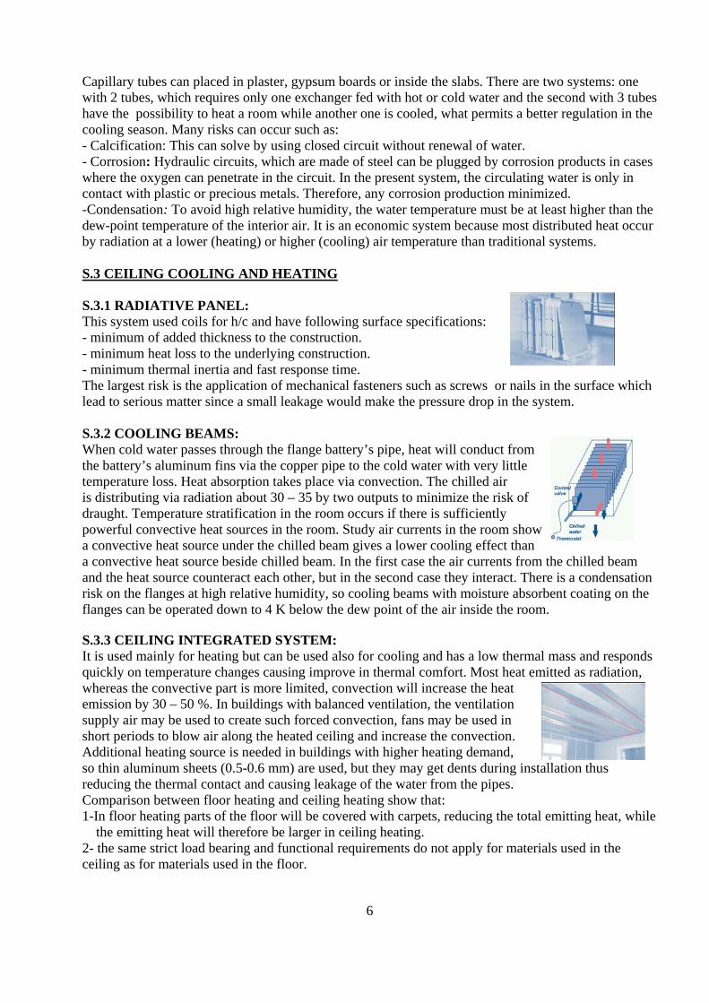
Capillary tubes can placed in plaster, gypsum boards or inside the slabs. There are two systems: one with 2 tubes, which requires only one exchanger fed with hot or cold water and the second with 3 tubes have the possibility to heat a room while another one is cooled, what permits a better regulation in the cooling season. Many risks can occur such as: - Calcification: This can solve by using closed circuit without renewal of water. - Corrosion: Hydraulic circuits, which are made of steel can be plugged by corrosion products in cases where the oxygen can penetrate in the circuit. In the present system, the circulating water is only in contact with plastic or precious metals. Therefore, any corrosion production minimized. -Condensation: To avoid high relative humidity, the water temperature must be at least higher than the dew-point temperature of the interior air. It is an economic system because most distributed heat occur by radiation at a lower (heating) or higher (cooling) air temperature than traditional systems. S.3 CEILING COOLING AND HEATING S.3.1 RADIATIVE PANEL: This system used coils for h/c and have following surface specifications: - minimum of added thickness to the construction. - minimum heat loss to the underlying construction. - minimum thermal inertia and fast response time. The largest risk is the application of mechanical fasteners such as screws or nails in the surface which lead to serious matter since a small leakage would make the pressure drop in the system. S.3.2 COOLING BEAMS: When cold water passes through the flange battery’s pipe, heat will conduct from the battery’s aluminum fins via the copper pipe to the cold water with very little temperature loss. Heat absorption takes place via convection. The chilled air is distributing via radiation about 30 – 35 by two outputs to minimize the risk of draught. Temperature stratification in the room occurs if there is sufficiently powerful convective heat sources in the room. Study air currents in the room show a convective heat source under the chilled beam gives a lower cooling effect than a convective heat source beside chilled beam. In the first case the air currents from the chilled beam and the heat source counteract each other, but in the second case they interact. There is a condensation risk on the flanges at high relative humidity, so cooling beams with moisture absorbent coating on the flanges can be operated down to 4 K below the dew point of the air inside the room. S.3.3 CEILING INTEGRATED SYSTEM: It is used mainly for heating but can be used also for cooling and has a low thermal mass and responds quickly on temperature changes causing improve in thermal comfort. Most heat emitted as radiation, whereas the convective part is more limited, convection will increase the heat emission by 30 – 50 %. In buildings with balanced ventilation, the ventilation supply air may be used to create such forced convection, fans may be used in short periods to blow air along the heated ceiling and increase the convection. Additional heating source is needed in buildings with higher heating demand, so thin aluminum sheets (0.5-0.6 mm) are used, but they may get dents during installation thus reducing the thermal contact and causing leakage of the water from the pipes. Comparison between floor heating and ceiling heating show that: 1-In floor heating parts of the floor will be covered with carpets, reducing the total emitting heat, while the emitting heat will therefore be larger in ceiling heating. 2- the same strict load bearing and functional requirements do not apply for materials used in the ceiling as for materials used in the floor.

7
3- thinner materials may be used in the ceiling than in the floor, so thermal resistance from the pipes to the surface will consequently be reduced for the ceiling heating systems. 4- the heated surface temperature has to be about 1°C degree higher for ceiling heating than for floor heating to emit 30 W/m². 5- by using same water temperature in the pipes, the total heat emission from ceiling heating will be about similar to that from floor heating. 6- ceiling heating systems have higher efficiency and lower additional heat losses than floor heating. Ceiling heating have another advantages such as - the larger exposed surface of the ceiling, and the lower temperature drop from the water in the pipes to the surface, will compensate for the lower convective heat emission form the ceiling heating. - ceiling heating systems are well protected against mechanical damage. S.3.4 EVAPORATIVE ROOF SURFACES: Evaporative cooling systems are based on the fact, that the phase change of liquid water into the water vapor requires energy, called latent heat. Evaporative roof surfaces mainly include the following techniques: - roof sprinkling: it is based on evaporation of a water mist layer which absorbs large amounts of heat. - roof ponds: it is consisting of water ponds being constructed over non-insulated flat roofs. - moving water films: it is based on the flow of a water film over the roof surface. The evaporation process is enhanced by an increase in the relative velocity between the air and the water surface. The cooled water is stored in the basement of the building and then circulated inside the building space, cooling it. This system doesn’t demand compressor, condenser and heavily insulated piping for refrigerant. Also evaporative cooling helps clean up the atmosphere since it has no CFC’s. But in hot and arid areas the water consumption must be minimized avoiding over-spraying and runoff. S.3.5 CEILING PANEL COOLING BY DOUBLE-ROOFING WITH WATER SPRAY: The figure shows a sectional view of the living room in which this cooling system is installed. The ceiling works as a radiant cooling panel and absorbs heat from the indoor space. Whenever the evaporation takes place, the temperature of the lower surface of the ceiling becomes quite lower than the outside air temperature. The rainwater is collected by the collector installed on the rooftop by gravity; so there is no use of electricity. The walls are thermally-well-insulated by a glass-wool cloth The interior side of the walls is finished with plasterboards to store the coolness from the ceiling and the coolness of the outside air during the nighttime. The combination of shading, radiant cooling by the ceiling and natural ventilation can provide the residents with acceptable and comfortable coolness. This system have many advantages such as Economic: it does not require conventional air conditioner, so the running cost is very small. Health: there is no necessity to care indoor air quality because this system demands natural ventilation. Environmental: it does not cause pollution since it has no CFC’s and CO2 emission.

8
Risks: Low indoor air velocity and high ceiling temperature may cause some discomfort, if sufficient natural wind hardly blow and the outside relative humidity is very high, in such a case the ceiling can not be cooled sufficiently by evaporation and indoor air current is hardly available. That mean evaporative cooling is more effective in dry climate . S.4 LOCAL HEATERS S.4.1 LOW TEMPERATURE RADIATORS/CONVECTORS DESCRIPTION: Panel steel radiators used as heat emitters in water heating systems with low temperatures. The range of typical values for the radiative part of the heat emission varies between 18 -57 %, while the ratio of the radiative and convective part of the heat emission is determined through the front area of the panel steel radiator and number and area of the convective sheet metals. The heating elements are fabricated using ferrous and nonferrous metals. Enclosure below the heating element becomes heated as air passes through the element, and leaves the enclosure through the outlet grille located above the heating element. Due to the use of water as heat transfer medium at a low temperature and pressure level, no technical risks should be expect such as smoldering of dust or dry air. But the operation of heating emission devices at low average heat transfer medium temperatures leads to a demand of a greater heat transfer area in comparison to high temperature radiators. S.4.2 RADIATORS INTEGRATED IN THE INTERIOR DESIGN: Tall radiators with large surface areas are required in this system, which could reduce the flexibility of the rooms when they are not carefully integrated into building. Water at temperatures close to room temperatures about 10-20°C for cooling and 20-40°C for heating circulate in radiators reducing losses in piping, slightly reducing the need for insulation and making the system more efficient. Condensation on radiator surface could occur if they operated below dew point, then dehumidification will improve thermal comfort for occupants. This system have many benefits such as: -Economic: Running costs are lower than air-conditioning systems especially for constant use. -Health: High level of comfort due to the radiant nature of heat transfer in rooms, especially in regions where summer climates are hot and humid. -Environmental: Radiant systems allow room design temperatures to be 1-3 K lower during heating and higher during cooling periods, leading to overall savings in exergy consumption. S.4.3 HIGH TEMPERATURE RADIATORS: This is an example of high-exergy heating; radiators are made of steel or cast iron and used for space heating in water heating systems. The range of typical values for the radiative part of the heat emission varies between 22 - 38%. These radiators also could be use as low temperature radiators depending on the system. Due to the relative high thermal capacity this radiators used in less insulated buildings with higher system temperature to improve thermal comfort. The heating emission devices operating at a higher temperature level leads to smoldering of dust or dry air what causes an unhealthy indoor climate. Higher exergy content from the energy source requires to produce the higher temperatures, but solar collectors and heat pumps work less effectively on high temperatures. S.4.4 BASE BOARD HEATERS: This system is suitable for small heating loads such as upper floors in one family house and consist of metal units mounted to a wall at or near the floor. They are defined by their heat transfer method; i.e.

9
radiant, radiant-convector or fin-tube with a metal enclosure. Water is the heat carrier used in all types. Placement of units along large portions of exterior walls provides optimal thermal and create good interior air circulation patterns. They cant be used for cooling purposes due to relatively small radiant surface areas and required convective with the need to drain condensate. In addition, integration to building structure may be difficult and have a negative impact on architectural features. Periodic cleaning of internal air channels is required. S.4.5 TRANSPARENT INSULATION: Plastic materials built into dividing walls to stop convection and to reduce radiation, called geometric media. It is recognize that if the walls are perpendicular to the propagation direction, every crossing through these barriers results in radiation loss due to the reflection to outdoor. Mainly there are two types of this material: capillary and honeycomb. The first having 2 mm diameter, the second have some centimeters and the section can be square or irregular. Irreversible physical and chemical transformations occur in the material during its life resulting in a degradation of the component. Characteristics and humidity or polluting aggression should carefully evaluate. More architectonically stimulating spaces can be created and the thermal performance is remarkable because U-values around 1 W/m2K are recorded.
A. AIR HEATING AND COOLING A.1 AIR TO AIR HEAT EXCHANGERS A.1.1 SENSIBLE ONLY HEAT EXCHANGERS / RECUPERATOR: Exchangers for sensible heat can recover latent energy only by condensing moisture and converting it to sensible heat. Usually these systems used when bacteria cleaning of airstreams, e.g. health care facilities is required, only small different between airstreams is required to gain small increase of input power. Risk for moisture condensation or frosting of the exhaust side exchanger surface is often occurring therefore methods to drain condensate and defrost this section must be provided. Condensation may occur in the supply side exchanger during summer. Cooling system load could increase if system is poorly controlled. A.1.2 COUNTER FLOW AIR TO AIR HEAT EXCHANGERS / RECUPERATOR: From thermodynamic a laminar heat exchange is the best solution for heat exchangers, this realize if the thermal distance between the cores of the warm and the cold flow as small as possible with thin highly conductive separating walls and maximal contact surface area. Laminar flow efficiency is much higher than turbulent flow; theoretically, an efficiency of 100 % is possible. One of the main difficulties is the connection of the canals with the collection canals. This problem solved by two steps: re-organizing canals by replacing every uneven column one canal-height vertically thus introducing rows with alternating supply and exhaust flows; omitting the walls closing the flow direction left and for the other right and so on. Thus low costs and energy efficiency about 90-95 % can realized. Latent heat released during the cooling process of the exhausted air avoids freezing, but increase moisture has a larger positive effect on avoiding freezing than increase of indoor temperature, DC fans often used in combination with heat exchanger because of energy efficiency more than 90% but it can give risk for extra noise. A.1.3 TOTAL (LATENT) HEAT EXCHANGERS / REGENERATOR: These units have the ability to transfer moisture from one air stream to the other. Re-cuperator types fabricated of a permeable material and transfer
10
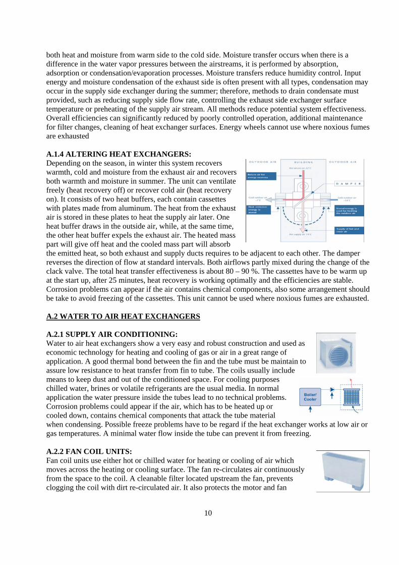
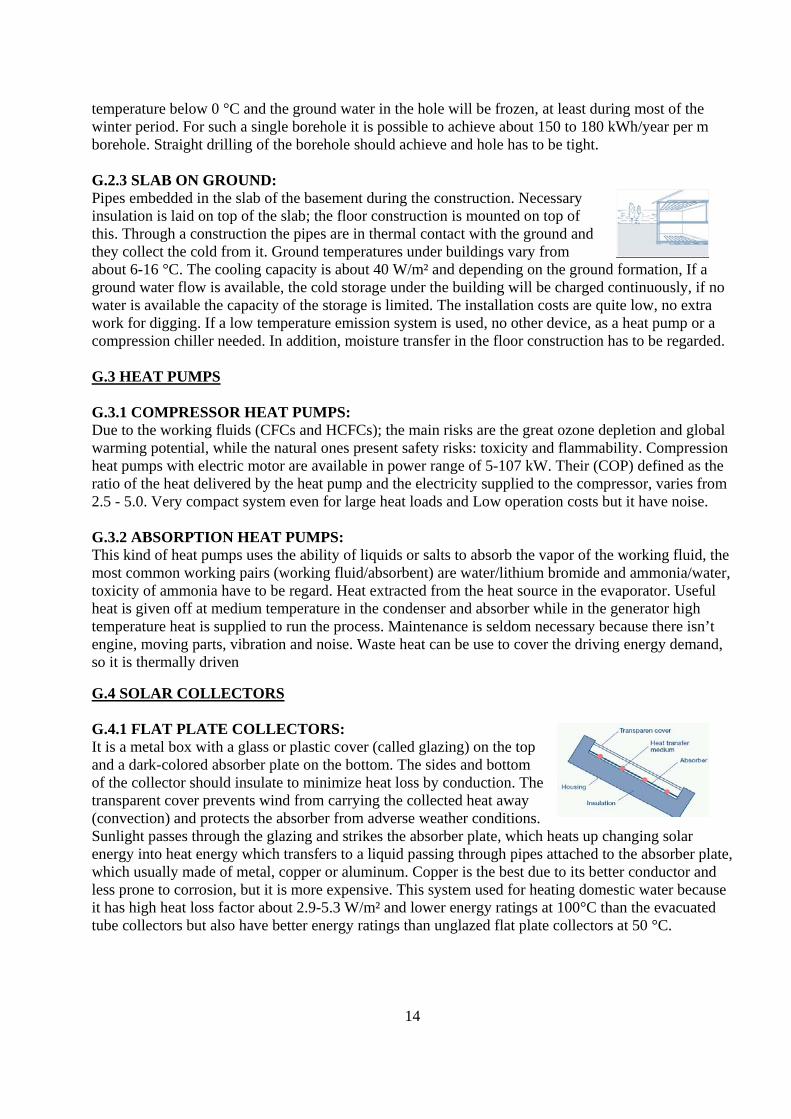
both heat and moisture from warm side to the cold side. Moisture transfer occurs when there is a difference in the water vapor pressures between the airstreams, it is performed by absorption, adsorption or condensation/evaporation processes. Moisture transfers reduce humidity control. Input energy and moisture condensation of the exhaust side is often present with all types, condensation may occur in the supply side exchanger during the summer; therefore, methods to drain condensate must provided, such as reducing supply side flow rate, controlling the exhaust side exchanger surface temperature or preheating of the supply air stream. All methods reduce potential system effectiveness. Overall efficiencies can significantly reduced by poorly controlled operation, additional maintenance for filter changes, cleaning of heat exchanger surfaces. Energy wheels cannot use where noxious fumes are exhausted A.1.4 ALTERING HEAT EXCHANGERS: Depending on the season, in winter this system recovers warmth, cold and moisture from the exhaust air and recovers both warmth and moisture in summer. The unit can ventilate freely (heat recovery off) or recover cold air (heat recovery on). It consists of two heat buffers, each contain cassettes with plates made from aluminum. The heat from the exhaust air is stored in these plates to heat the supply air later. One heat buffer draws in the outside air, while, at the same time, the other heat buffer expels the exhaust air. The heated mass part will give off heat and the cooled mass part will absorb the emitted heat, so both exhaust and supply ducts requires to be adjacent to each other. The damper reverses the direction of flow at standard intervals. Both airflows partly mixed during the change of the clack valve. The total heat transfer effectiveness is about 80 – 90 %. The cassettes have to be warm up at the start up, after 25 minutes, heat recovery is working optimally and the efficiencies are stable. Corrosion problems can appear if the air contains chemical components, also some arrangement should be take to avoid freezing of the cassettes. This unit cannot be used where noxious fumes are exhausted. A.2 WATER TO AIR HEAT EXCHANGERS A.2.1 SUPPLY AIR CONDITIONING: Water to air heat exchangers show a very easy and robust construction and used as economic technology for heating and cooling of gas or air in a great range of application. A good thermal bond between the fin and the tube must be maintain to assure low resistance to heat transfer from fin to tube. The coils usually include means to keep dust and out of the conditioned space. For cooling purposes chilled water, brines or volatile refrigerants are the usual media. In normal application the water pressure inside the tubes lead to no technical problems. Corrosion problems could appear if the air, which has to be heated up or cooled down, contains chemical components that attack the tube material when condensing. Possible freeze problems have to be regard if the heat exchanger works at low air or gas temperatures. A minimal water flow inside the tube can prevent it from freezing. A.2.2 FAN COIL UNITS: Fan coil units use either hot or chilled water for heating or cooling of air which moves across the heating or cooling surface. The fan re-circulates air continuously from the space to the coil. A cleanable filter located upstream the fan, prevents clogging the coil with dirt re-circulated air. It also protects the motor and fan

11
and reduces the level of airborne contaminants within the conditioned space. A condensate removal system should always install on the thermal units. Fan coil unit capacity can controlled by coil water flow, air bypass, fan speed etc. Water flow can thermostatically controlled by return air or wall thermostats. By using a dampered opening in the outside wall especially in cold climates a freeze protection for the unit should be provide, also air regulation problems should appear, because wind pressure prevent control over the amount of outside air that is admitted. Units with the preheating of fresh air in winter offer the possibility to reduce the required heating power and to lower the costs for the heating equipment. The capacity of the ventilation air unit is determine by the total design ventilation rate of the spaces. A.3 STEAM / VAPOUR TO AIR HEAT EXCHANGERS A.3.1 SUPPLY AIR CONDITIONING: Steam to air heat exchangers show a very easy and robust construction. They can be use as economic technology for heating of gas or air without technical risks. Regarding non-condensable gases, which remain in the coil, may cause chemical corrosion and resulting early coil failure. Properly designed and selected steam distribution coils distribute steam throughout the full length of all tubes. In load situation, less than full load conditions, the air can bypassed around the steam coil with full steam kept in the coil. Piping controls and installation must be design to protect the coils from freeze-up due to incomplete draining of condensate. A.4 OTHER HEAT EXCHANGERS A.4.1 SUPPLY AIR FAÇADE: Metal cladding mounted several inches from the outer wall of the building and completely covered with tiny perforations. The outside air passes through the metal panels during the day and absorbs solar heat generated on the cladding, this heated air rises between the walls and draws into the building ventilation system, its temperature about 17 – 30 °C depending on the flow. During the night, the supply air façade acts as a heat recovery unit by recuperating the heat loss across the wall, which is picked up in the incoming air and is brought back into the building, it can even cool a building down in the summer. Snow on the ground is advantageous because it reflects up to 70% of solar radiation, 40 % on the cladding, just because it is cloudy does not mean that the supply air façade cannot absorb solar radiation. Diffused light on cloudy days can represent up to 25 % of solar radiation that is available on sunny days. The most important technical benefit is the simplicity of this low exergy technology, there are very few moving parts and maintenance is virtually non-existent, also it has very little added costs to a project because wall components and building ventilation equipment are replaced instead of added. For fan efficiency and optimal free cooling operation, equalization of the static pressure losses of the two different conduits is necessary. The very small perforations block the entry of the larger dust particles that normally enter in conventional outdoor air duct configurations. This increases filtration efficiency and improves indoor air quality.

12
A.4.2 EVAPORATIVE COOLING: These systems based on the fact that the phase change of liquid water into the water vapor requires energy, called latent heat, it occurs without a temperature change, when non-saturated air gets in contact with water. In the case of direct evaporative cooling there is direct contact between the air and water and the air moisture content is increased. Its efficiency depends on the saturation level of the air more than on the temperature of the cooling water, sufficient ventilation is required to avoid the increasing of humidity ratio of the incoming air. The air can even cool with water, which is warmer than the air itself. When the air gets hotter, it can absorb more moisture and then evaporative cooling is more effective. In the case of indirect evaporative cooling circuits of the water and air are separated, and the humidity ratio of the air does not change (even though the relative humidity increases because the temperature decreases). Passive evaporative cooling is a simple and natural process, consists only of a wetted cooling media, such as vegetation, fountains, sprays, and tower cooling. This simple method is not very efficient. One of the newest and most efficient media is a “rigid media” it can filters to near 1 micron size particles out of the air, helps to protect the atmosphere since it has no CFC’s and achieve even 99 % efficiency. Evaporative cooling doesn’t need compressor, condenser and heavily insulated piping for refrigerant, also it demands simple maintenance and its energy consumption is smaller than that of conventional systems, so its cost is very small. This system is best suited in buildings with small cooling loads and ineffective in humid climates and works best when relative humidity is below 70 %. A.5 PASSIVE SYSTEMS A.5.1 ATRIA: An atrium is an open, central area with the complete height of a building, which is surrounded by residence areas. It is using as traffic place and in warmer climates as shaded inner area. When an atrium covers with glass it can be use as a natural cooling tower called chimney effect, because warm air is removed from the area to the roof, but perhaps not always able to produce the required cooling effect. In theory, an atrium can participate in building heating during winter, if the air is not removed. In practice, it appears that the air temperature becomes too high too fast. An atrium gives visual benefits; it gives an open and bright appearance while on other hand it requires much more space, which can use for other purposes. A.5.2 SOLAR CHIMNEYS: A solar chimney works as a natural draft device that uses solar radiation to move air upwards. The draft produced in the chimney depends on the temperatures difference between the inside and the outside air, as well as, on the chimney height, which effects on the rate of the heat losses that exceed height chimney will lead to cool the air to the same temperature as ambient, so optimum height should be consider. If the chimney is designed properly to keep the air temperature within it higher than ambient throughout the height of the chimney, cooling within the chimney would not be the critical factor in determining the suitable chimney height. - During winter; with a uniform resistance to air-flow across the floors of the considered building and to flow into the shaft at each floor level, air enters the shaft at lower levels and leaves it at higher levels in a symmetrical pattern. The neutral pressure occurs near mid height of the shaft and the pressure difference across the wall of the shaft maximum at the top and bottom.- During summer; solar chimney can be used for free cooling. Whenever the outdoor air temperature is higher than indoor, the

13
pattern of pressure differences and airflow reverse of the winter one. Then stack effect is much less than under winter conditions because of the smaller driving force, i.e. inside-to outside air temperature difference. This device works in the medium seasons, because of the sun-heated top during the day, which enhances the stack-effect. This kind of technology affected greatly by the ambient conditions but essentially available at no cost, except some maintenance for cleaning. G. GENERATION / CONVERSION OF COLD AND HEAT G.1 BOILERS: G.1.1 CONDENSING BOILERS: Use the heat, by condensing the moisture contained in the exhaust gas, in addition to use the lower part of the heating value of the chosen energy carrier, as natural gas or oil. They have highly efficient but need bigger heating surfaces / radiators or floor heating due to the lower heat supply temperature. G.1.2 PULSATING GAS BOILER: It is a boiler with a combustion chamber entirely immersed in water. The exit of the combustion chamber connects with a network of spiral tubes, which allow an optimal thermal exchange with the fluid. An air – gas mixture introduces in the combustion chamber producing micro combustion. The combustion gases escape by the exchanger tube bundle creating a depression, which gives rise to the next arrival of air – gas mixture, also producing a turbulent flow. In spite of its expensive cost compared to a classic boiler it have a very low smoke temperature and doesn’t need extraction fan, therefore it consumes 4 to 8 times less electricity than a boiler with an extraction fan, simple PVC tube is sufficient to evacuate the combustion gases, which have a maximum temperature of 50 °C. It has constant performance over the time, self-cleaning and without a burner which may break down. G.2 GROUND HEAT G.2.1 GROUND COILS: The heat extraction from the ground is done via plastic pipes in the ground, in depth about 1.2-1.5m and in distance about 0.5- 0.7m, per m² heat collecting area 1.5 to 2 m pipes should be used, the total length of one pipe should not exceed 100 m, otherwise necessary pumping energy increases hardly. The liquid heat-carrying medium is pumping through the coils and the stored heat in the ground is taking up and normally used for space heating by means of a heat pump and a floor heating system. It is possible to extract approximately 20-40 W per m² as an annual mean value. Cooling with ground coils is also possible by using the ground temperature about 6 - 8 °C. It is easy, cheap design and large ground areas are necessary to provide a required power output. For buildings with a good thermal standard, the heat collecting area equals the heated space area, for buildings with a lower standard it could be twice as much area. The temperature of the heat source is relatively equal over the year and ground can considered as a long term storage for solar heat. Plants with long roots could damage the pipes and if the ventilation air is directly pre-heated or pre-cooled in ground ducts, there is a risk for accumulation of dirt and moisture inside the pipes and the necessary cleaning can be difficult and mould growth could be result leading to health problems. G.2.2 BORE HOLE: Use as a heat/cold source with deep 100-150 meters and about 120 mm in diameter and 35 mm inner diameter, normally connect to a heat pump and typically used for solid rock grounds. The pipe is inserted as a U-tube in which a ”brine” circulates in
14
temperature below 0 °C and the ground water in the hole will be frozen, at least during most of the winter period. For such a single borehole it is possible to achieve about 150 to 180 kWh/year per m borehole. Straight drilling of the borehole should achieve and hole has to be tight. G.2.3 SLAB ON GROUND: Pipes embedded in the slab of the basement during the construction. Necessary insulation is laid on top of the slab; the floor construction is mounted on top of this. Through a construction the pipes are in thermal contact with the ground and they collect the cold from it. Ground temperatures under buildings vary from about 6-16 °C. The cooling capacity is about 40 W/m² and depending on the ground formation, If a ground water flow is available, the cold storage under the building will be charged continuously, if no water is available the capacity of the storage is limited. The installation costs are quite low, no extra work for digging. If a low temperature emission system is used, no other device, as a heat pump or a compression chiller needed. In addition, moisture transfer in the floor construction has to be regarded. G.3 HEAT PUMPS G.3.1 COMPRESSOR HEAT PUMPS: Due to the working fluids (CFCs and HCFCs); the main risks are the great ozone depletion and global warming potential, while the natural ones present safety risks: toxicity and flammability. Compression heat pumps with electric motor are available in power range of 5-107 kW. Their (COP) defined as the ratio of the heat delivered by the heat pump and the electricity supplied to the compressor, varies from 2.5 - 5.0. Very compact system even for large heat loads and Low operation costs but it have noise. G.3.2 ABSORPTION HEAT PUMPS: This kind of heat pumps uses the ability of liquids or salts to absorb the vapor of the working fluid, the most common working pairs (working fluid/absorbent) are water/lithium bromide and ammonia/water, toxicity of ammonia have to be regard. Heat extracted from the heat source in the evaporator. Useful heat is given off at medium temperature in the condenser and absorber while in the generator high temperature heat is supplied to run the process. Maintenance is seldom necessary because there isn’t engine, moving parts, vibration and noise. Waste heat can be use to cover the driving energy demand, so it is thermally driven G.4 SOLAR COLLECTORS G.4.1 FLAT PLATE COLLECTORS: It is a metal box with a glass or plastic cover (called glazing) on the top and a dark-colored absorber plate on the bottom. The sides and bottom of the collector should insulate to minimize heat loss by conduction. The transparent cover prevents wind from carrying the collected heat away (convection) and protects the absorber from adverse weather conditions. Sunlight passes through the glazing and strikes the absorber plate, which heats up changing solar energy into heat energy which transfers to a liquid passing through pipes attached to the absorber plate, which usually made of metal, copper or aluminum. Copper is the best due to its better conductor and less prone to corrosion, but it is more expensive. This system used for heating domestic water because it has high heat loss factor about 2.9-5.3 W/m² and lower energy ratings at 100°C than the evacuated tube collectors but also have better energy ratings than unglazed flat plate collectors at 50 °C.

15
G.4.2 EVACUATED TUBE COLLECTORS: They are rows of parallel transparent glass tubes, consists of a glass outer tube and inner tube that covered with selective coating which have excellent solar heat absorption and minimal heat reflection properties. The space between the two glass tubes evacuated from air to form a vacuum and thus eliminate conductive and convective heat loss. These collectors still provide excellent results on cloudy days due to the ability of absorb the energy from diffuse radiation also wind and low temperature have a limited effect due to the good insulating properties around the collector. Furthermore, the sun is always striking the tubes at right angles, thus minimizing reflection. Thermal heat loss factor is lower than that of the other collectors. They designed especially to operate at high temperatures and show their highest performance at 100 °C. G.4.3 UNGLAZED FLAT-PLATE COLLECTORS: Especial design for low temperature applications such as the heating of swimming pools, and usually made of black plastic. They have a high heat factor loss because they haven’t insulation or glazing then a larger portion of the sun’s energy is absorbed and a large part of the absorbed heat loss happened under windy and cool weather. They are very efficient at low output temperatures their efficiency declines dramatically as the temperature of output increases and produce high energy ratings at 35 °C, low ratings at 50 °C and zero at 100 °C. G.5 COMBINED HEAT AND POWER GENERATION G.5.1 COGENERATION UNITS WITH GAS MOTOR: It is used for the production of hot water and hot air for household or small industries. The electrical power going from about 5 kW to several MW, electric efficiency varies between 28-40 %, the thermal efficiency between 51-59 %, giving a global efficiency of 85-91 %. The motor is usually driving by domestic fuel, natural gas or biogas. For a comparable electrical power, a unit with gas motor delivers less thermal energy than one with a combustion turbine because of the rotating components of the motor. This kind of cogeneration units has higher maintenance compared to those with gas turbines. G.5.2 COGENERATION UNITS WITH MICROTURBINES: Gas turbines used for smaller applications with power outputs of 25 - 200 kW and usually have electric efficiencies of 25-30 % and total efficiencies of 75- 80 % and offer a high reliability (95-97%), long service intervals and long life times. Because of their simple construction, the shaft with compressor, turbine and generator being the only moving compound, thus they have a relatively low noise level and low emission level. Compared to other power generating systems micro turbines have relatively high investment costs compared to a system with gas motor. G.5.3 COGENERATION UNITS WITH STIRLING MOTOR: A working medium (air, helium) is heating by an external heat source and cooling by removing it from the source. There are different types of Stirling motors: - One-cylinder motor (type beta): contains two pistons, a working piston and a displacer piston, which brings the working medium alternately in contact with the hot and the cold source. - Two-cylinder motor (type alpha): one cylinder linked with the cold, the other one with the hot source. A high working pressure has to be maintained in order to achieve an acceptable efficiency. The power ranges of 60We - 25 kWe, the electrical efficiency varies between 20-40 %. For cogeneration units the thermal efficiency is about 65-75 %. The absence of an internal combustion makes the Stirling engine

16
accept many kinds of fuels (natural gas, domestic fuel, and biomass). In addition, solar energy might be used as energy source, for the same reason it has a low noise level and very low emission level, due to the burnt air doesn’t enter, the engine is insensible to dust. If hydrogen used as working fluid, special expensive alloys have to be used to prevent corrosion problems. G.6 FUEL CELLS G.6.1 FUEL CELLS: It is an electro-chemical device used to produce electric and thermal energies from the reaction of an oxidizer (combustive) and a reducer (fuel), which can be gas, liquid or solid. A fuel cell consists of two electrodes: 1- an anode (-) where the fuel is provided. 2- a cathode (+) where the combustive is provided. Differences between fuel cells especially concern the working temperature, fuel requirements and the size of the battery. The use of fuel cell is possible at two levels: - the level of an urban heating that produced electricity supplies the public network. - the level of a house or a building because the produced electricity is largely auto consumed. At the first the power of the fuel cell is several hundreds of kWel, in the second case the power is about 5 to some tens of kWel. The production of hydrogen as fuel have the following aspects: - if hydrogen is produced from the solar electrolysis, it can be use the photovoltaic electricity directly. - if hydrogen is produced from gas, there is emission of CO2. - the storage of hydrogen (especially for the mobile applications) - cost and the maturity of the product and the industrial sector. Some risks exist principally due to the distribution, use and way of storage of hydrogen. The future of fuel cells is very promising for the following reasons: - the electro-chemical production mode very weakly polluting and silent due to absence of emissions. - the possibility of a cogeneration, with a very high electric efficiency. - the efficient use of primary energy. - the suppleness of the decentralized production of electricity. G.7 BIOLOGICAL SYSTEMS / METABOLIC G.7.1 BACTERIA: In each living cell there is a series of enzymes that govern its chemistry. A slow low-temperature converts the stored energy of foodstuffs into chemical potential with the least possible energy loss as heat. In an ordinary steam engine, fire from wood, coal, or oil converts all the stored chemical energy to ash and heat. In a typical car engine, 25 % of the combustion energy turned into useful work while 75 % is lost as heat. In a cellular system much less of the energy is thermalized that substantial amount is stored as chemical potential in molecules. Which have more efficient than the car that 40 % of the combustion energy is conserved and 60 % lost as heat. G.7.2 ANIMALS: Heat from the animals has used as basic heating. A cow at rest produces a sensible heat of 250 W. This heat generation system is only suitable to farm-houses or buildings, where a lot of animals are kept, also heat source is not available at all times because animals should be left outdoors, in addition to risks of spreading smell and contamination gases to the living zone. However, placing the stables below the house shortens the working distance for the farmers and makes it easier to supervise the animals.

17
G.7.3 PLANTS: Large plants or amount of plants can placed inside the room for cooling purposes. High relative humidity inside is possible due to the evaporation of water, so care should be taken to prevent paper from buckle. Possible condensation on colder surfaces has to be taken into account. The plants can give the interior of the room a natural look and need light, so a good daylighting strategy is necessary. T. THERMAL STORAGE T.1 SEASONAL STORAGE T.1.1 GROUND / ROCK STORAGE: Ground storages are an economic alternative because they require relatively low investment costs. Soil, sand, rock, clay etc are using for storage thermal energy. A borehole storage system consists of a number of holes, which drilled into the storage medium to a depth of 50-100 m. A tube inserted in each hole and delivers fluid to the bottom of the hole. Heat pump transfer fluids through pipe arrays in the ground, then the fluid passes up in contact with the storage medium. Higher storage volumes are needed in comparison to water storages because ground storage have low relatively thermal capacity and low thermal conductivity compared with water, due to these features a lower charge and discharge thermal power can be realized in comparison to water storages. Great ground water flows lead to high thermal losses and insufficient storage that about 60 % of the energy that is added can be extracted to provide heat. Another problem is the blocking of the filters due to particles in the water and the main risk is the geological conditions in the ground. In addition, a great amount of the supplied thermal energy of the first two years of operation is needed to heat up the surrounding ground. The maximal storage temperature by using clay as storage medium is about 40 °C, higher temperature levels can be reached if granite is used as storage medium. Temperatures in deeper drilled boreholes can reach to 100 °C. T.1.2 EARTH DUCT STORAGE: Soil or rock used as heat storage medium. The circulation of water through heat exchanger ducts realizes charging and discharging of the heat. The probes usually have a diameter about 150 mm and a depth about 30 –150 m, the distance between the probes should be1.5 (clay) to 3 m (rock). After putting U-pipes in the probes, they filled with material of a relative high thermal conductivity and thermal insulation is installed at the surface area to reduce the heat losses. The storage temperatures reach about 45-75 °C and its volume can be extended in several steps so it can be adapted to residential area. Due to low thermal conductivity of the walls earth, duct storages should have great volumes (more than100 000 m³) to reduce the relative heat losses. The construction of earth ducts as seasonal storage leads to relatively low investment costs in comparison to steel tank storages. T.1.3 HOT WATER STORAGE: It is used for both short and long-term storage. It divided into two main types: - For short-term storage, self-carrying steel tanks are a common use with volumes up to 5000 m³. However, its construction is expensive. - Earth pits as seasonal storage directly built in the soil acting as carrying element with volume about 3 000- 80 000 m³. Due to the use of water as storage medium, high charge and discharge power realize between 35-95°C. Water has relatively high storage capacity at greater differences between supply and return temperature. The soil has to be soft and the earth pit storage has to be provided with a water resistant and sustainable coating such as stainless steel on the inside of the walls. The thermally insulated ceiling considered as supporting structure. Storage volumes of round about 50 000 m³ have to be provided with a thermal insulation to reduce the heat losses

18
T.1.4 PHASE CHANGE THERMAL STORAGE: It must be available to store the material and transfer heat into it and out of it. It can operate over small temperature ranges, have relatively low volume and mass and have high storage capacities. Its media usually placed in small containers or shallow trays to provide a large heat transfer area. The heat transfer fluid is usually air or water. Because of the high inlet cooling temperature, the system can supplied with cold from the ground under the building or other nearly free sources. Phase change materials often have poor thermal conductivity, so the ways for the transport of the heat have to be short in case of discharging. Changes of the material volume cause the formation of cavities, which leads to a higher thermal resistance within the material. T.2 SHORT TERM STORAGE T.2.1 BUFFER STORAGE TANK: The cylindrical tank provided with threaded connections for the different charging and discharging circuits. The buffer storage tanks normally filled with the same heat or cold transfer medium that is used in the connected circuits, water is the common medium, which leads to low storage volume due to its high thermal capacity, and it is not harmful to the environment so no expensive measures against leakage have to be taken. The main function to this system is to buffer the heat or cold produced by a not adjustable generator (solar thermal unit, wood boiler etc.) for the later deliverance to the emission devices. They used also for the hydraulic decoupling of the source (boiler, solar plant) and the emission part (radiators, floor heating systems). Furthermore the terms of operation of the source components increase, which leads to a reduction of emissions and losses. Advanced kinds are equipped with stratification devices to store the heat or cold in that height of the storage corresponding to their density and temperature. Service life between 25–30 years and they provided with thermal insulation to reduce the losses, which lead to a relatively high space demand and higher costs. T.2.2 DOMESTIC HOT WATER TANK: They are available from about 3 l for electrically heated tanks up to about 1500 l and operate under ambient pressure what leads to low installation costs but high operating costs due to the use of electricity. Stainless steel or ceramic-coated are used as construction material to avoid corrosion. DHW tanks can directly integrated in the boiler or can be installed beside, under or above the boiler. The heat exchanger for heating water can directly integrated in the tank. As heat transfer medium is steam, heating water or district heating water. The advantage of this store system is the possibility to reduce the power of the connected heating system in comparison to flow systems used for the domestic hot water preparation. While in storage systems a defined volume of water is kept on the desired temperature continuously, in flow systems all power for the heating of the water have to be delivered from the heating system at the moment of demand.

19
D. DISTRIBUTION D.1 TRANSFER MEDIUM D1.1 AIR: When air used as a heat carrier, the air moves freely in the room. The pipes that distribute the air are mostly the same that used for ventilation. Air is non-toxic, free and available anywhere. The heat capacity is very low about four times lower than water. Therefore, a big amount of air is needed. D.1.2 WATER: The most important technical characteristics of a heat-transfer fluid are a low freezing point, stability, physical properties and low corrosion. Water has the all except a low freezing point, which lead to certain risk. It is a cheap and non-toxic fluid with good availability. D.1.3 “THERMERA” HEAT CARRIER: The main characteristics of a thermal fluid are a good heat-transfer capacity and a low environmental impact, (that is non-toxic, safe to use and easy to dispose of or recycle), and the total costs over the product’s life cycle. Thermera® is a new low-impact heat transfer fluid, have superior environmental characteristics than conventional heat-transfer fluids, also It has anticorrosion properties, designed for use in closed circuits with an operating temperature range about (-38 °C to +80) °C (fluid temperature) and its thermal performance is equal to that of traditional thermal fluids. Its investment costs are higher than for a conventional fluid, however, the life cycle costs are lower. D.1.4 GLYCOL: Whole family of ethylene glycols have toxicity effect that large spills or releases of the chemical can result in a short-term stress on the immediate environment by rapidly consuming oxygen during the biodegradation process. The propylene glycols are another family of products, some of which considered safe at relatively high concentrations in food, pharmaceutical, and cosmetic products. Ethylene glycol (EG) will cause adverse effects when breathed, because liquid EG does not readily become a gas by evaporation due to its low vapor pressure, toxic when ingested. Data for all glycols indicate that both ethylene glycol and propylene glycol are readily biodegradable, and thus will not accumulate in the environment. The investment costs are lower compared to more environmental friendly fluids that can stand low temperatures. D.2 COMMUNITY SYSTEMS D.2.1 DISTRICT HEATING: It helps conserve energy and the environment because heat generated by renewable energy sources e.g. waste, industrial production. It produces at CHP plants, which lead to optimize the use of fuel with minimum wastage. The temperature of DHW varies between 65-115 °C depending on the weather, while returning water temperature ranges between 25-50 °C. DHW heats the water that flows through the heat exchangers and then used for the building's space heating system and for hot service water. Temperatures inside the building kept correct and steady by means of control devices. A control valve regulates the volume of district heating water flowing through the heat exchanger according to the outside temperature. DH can use with radiator, floor and air heating in low temperature systems. Radiator with low temperatures means bigger radiators and higher investments. Due to the use of water as heat transfer medium at a low temperature and pressure level, no technical risks have to expect.

20
D.2.2 DISTRICT COOLING: DC is a system in which chilled water generated by compressor, absorption chiller or other sources like ambient cooling or "free cooling" from lakes, rivers or oceans and distributed in pipes from a central cooling plant to buildings for space cooling and process cooling. DC system contains three major elements: the cooling source, a distribution system and customer installation. Cooling generation may also happened by thermal storage to reduce chillers' equipment demands and lower operating cost by shifting peak load to off peak times. 4.3 LOWEX SYSTEM CONCEPTS One example of a LowEx system is the use of boreholes to provide cooling in summer. but boreholes will gradually over the years become warmer and above the temperatures that could be used for direct cooling. By extracting heat in wintertime with a heat pump, the heat balance of the hole is restored and the system solution becomes sustainable in time. In most cases where exergy is consumed at different temperature levels in a thorough system study can lead to substantial savings. 4.3.1 THERMONET SYSTEM CONCEPT FOR HEATING AND COOLING: It is based on two factors: an air heating system that uses low temperature technology, and efficient energy recovery. By applying ThermoNet technology, the consumption of purchased energy may be cut by more than one half when compared to conventional solutions, and electrical consumption may be reduced to one third. It is able to use DH, reducing peak loads by 60-70 %. 4.3.2 HEATING AND COOLING WITH ARE SENSUS: The exergy consumption of the Sensus® system is lower than in comparable high-standard systems, which decreases environmental impact during use. The ventilation units use surplus heat collected from the rooms with the cooling water system for the heating of intake air whenever heating is needed and use the outdoor air for cooling the cooling water for the rooms when outdoor temperature is sufficiently low (under +12–14 °C) thus free cooling carried out with ventilation units when necessary. These causes conserve heating, cooling exergy and reduce electricity consumption of cooling unit. There is thermal radiation from the panel on both people and the surfaces of the room, Therefore the panel produces a more even distribution of heat in the room than radiator heating. Studies showed that ceiling cooling is the most pleasant way to cool office and workspace. People will feel coolness but no draught. The panels installed at a distance of about 150 mm from the ceiling or inside floor. Ventilation: Supply air conducted into the rooms through supply air diffusers, which installed beneath and along the panel. Ventilation is draught-free; because the air keeps well to the smooth panel and at the same time the surface of the panel will heat or cool the intake air according to the requirements of the room. Lighting: The lighting fixes under the panel providing very high quality indirect lighting and using energy saving T5 fluorescent tubes. Although the panels have a high reflectance of light, they are not shiny. Therefore, the required electrical power for the lighting is low and electricity consumption is also low. Temperature control: A single electronic temperature control unit regulates heating and cooling in series, each room has a separate control unit, which improves interior conditions, and reduces exergy consumption. And both heating / cooling are mainly supply by thermal radiation which improve the control, thus adjustment is quick, where in traditional designs heating and cooling are conducted through the air with slow effect on room temperature. Electricity The connection cables of the workstations placed freely above the panels. The socket columns can placed or moved where desired in the workstation area.

21
4.3.3 CEILING COOLING WITH WELL WATER: During the first hour of cooling system operation, temperature in the room was 28.5 ºC, with and without sun shading. Thereafter, the effect of outdoor sun shading on temperature became clearer. In the case with outdoor sun shading (dark line), the temperature remained relatively constant until the cooling ceiling was turned off and the sun shading removed at 16:00. In the case without shading (light line), the temperature gradually rose and reached 30.5 ºC at 16:00, in spite of the cooling provided by the ceiling radiant cooling system. These results show how the room indoor thermal environment benefits from outdoor sun shading. The indoor thermal environment realized by means of supplying and consuming thermal exergy of well water and electricity at the ceiling radiant cooling system. 4.3.4 NEW INNOVATIVE HEATING CONCEPT: The energy source is ground heat; heats extracted through a heat pump which uses electricity, about one third of its supplied energy amount. The emission system is a floor heating with phase change, which store the energy from a solar collector during the day and released it to warm up the room during the night. The same could also be used during the night and releasing the heat during the day “charging itself”. The system designed to cover the peaks that occur during the day. Figure shows exergy analysis of a floor heating system using a heat pump as energy generator. Looking at the electricity distribution system, there is an overload in the network during the night. 4.4 4 4.4 STRATEGIES FOR DESIGN OF LOW EXERGY SYSTEMS IN BUILDING The aim of the design process is to make energy efficient buildings that can provide the occupants with comfortable, clean and healthy environment. The different parts should work together optimally and process at least should be an iterative process. The quality of the choices made should confirm by general system analysis, which should include at least: - Energy analysis – heating, cooling and lighting. - Exergy analysis – heating and cooling. - Reference temperatures. - System boundaries in both space and in time. - Embedded exergy. - Economy. - Investment cost. - Operational cost. - Maintenance cost. - Cost for dismounting and waste treatment. - Flexibility.

22
5. EXAMPLES OF LOWEX BUILDINGS: the case examples give strong evidence that in addition to the desired heating or cooling effect, LowEx systems can provide occupants with a comfortable, clean and healthy environment. 30 case examples of LowEx buildings from 11 countries are presented, but the most important examples will describe in the following:
1- 421 DOWNEY ROAD BUILDING, CANADA:
In this building advanced design principles is achieved to realize main objectives: 1) Provide more environmentally friendly and productive workspaces. 2) Provide flexible spaces to accommodate a variety of tenant requirements including laboratory space. 3) Reduce energy use to 35 % less energy than the Model National Energy Code. 4) Provide all of the above goals all for no additional capital cost.
2- BLOMSTEDT HALL, FINLAND:
A Sensus system, which includes the design and installation of systems, is applied for heating, cooling, ventilation, electricity, lighting, fire protection, water and sewage. Primarily it uses the waste heat from the building for heating. When additional heating is need, it will deliver with a heat exchanger from the district heating network. Cooling is primarily delivering by free cooling. When this is not enough, the system uses vapor compression chillers to cool the cooling water. Water is passing in the ceiling panels to heat or cool the rooms in the building, each room has individual control for temperature. The panels are also using as a reflecting element for the indirect lighting. There is a demand controlled ventilation system (Nemus®), which maintains the duct pressures at an optimal level. The automation system is controlled by both temperature and occupation sensors. This system has mechanical ventilation with heat recovery.

23
3- HOTEL DE CROY PARIS, FRANCE :
The technique of heating and refreshing ceiling (by radiation) is adapted and a high level of comfort is reached. Moreover, this system remains invisible and does not generate any noise. Set point temperatures: Winter: 20 ± 2 °C, Summer: 24 ± 2°C Input temperatures in the emission system: Cooling: min.16°C, Heating: max. 32 °C Emission system: Network of low diameter polypropylene pipes (2 mm) in the ceiling Ventilation: Air processing power station COMFORT: The measured maximum vertical temperature gradient between 10 cm and 3.90 m was 1°C (in winter). Occupants satisfied with comfort, in particular the absence of noise and air movement, no filter to be replaced or tank to be cleaned. The main disadvantage of this technique is its cost (270 € /m²). The low cost of maintenance and the high level of comfort may allow this system to expand in a near future.
4- NESTLE FRANCE HEAD OFFICE NOISIEL, MARNE-LA-VALLÉE, FRANCE
Most of the retrofitted buildings are equipped with heating and cooling ceilings. The major reason of that choice chilled ceiling air conditioning system associated with displacement ventilation, was the expected low energy consumption, the silent running and the savings of room and floor surfaces. Outside walls of the retrofit ted have been insulating. Each window (double-glazed) is equipped with external shading device, automatically operated according to solar radiation. Ceiling used for both heating and cooling. For heating, it is only a part

24
of the system; the other is done by air heating. Panels connected to a water loop from the heat exchanger to rooms. The AHU are equipped with heat recovery coils, which enable to reduce heat losses due to the ventilation. Controls in rooms enable to adjust heat supply to the actual demand. Panels connected with each other by an individual loop of polypropylene pipes: 16/20 mm. Each loop supplies only one room with a maximum of 15 panels. Control temperature: Winter 20°C, Summer 24°C. (“Higher” and low temperatures for “cold returns” to generation)
Input temperatures in the emission system: (Cooling15.5°C return18.5°C), (Heating 33°C, return30). Ventilation: Double-flux heat recovery to pre-heat the incoming air. Anti-condensation safety control. HEATING-UP AND COOLING-OFF: Heating: Ceilings supplied by hot water for a temperature drop of 3 °C (33/30 °C), thermal power reaches 45 W/m2. In some rooms, the heating is provided by local emitters or heating floors. Cooling: Radiating ceilings bring some constraints that cooling power is limited 70 W/m2 with the type used and to prevent condensation, the temperature kept above the dew point. AIR TREATMENT AND CONTROL STRATEGY: Air incomes by the floor close to facades (very low speed entrances), it’s exhausted on the upper part of opposite partitions. Air treatment units are equipped with heat recovery coils to pre-heat the new air incoming in winter. -Control of room temperature: Water flow circulating in panels controlled by slow action valve operated by a room air thermostat set on the wall of each room, - Control of new air temperature by a sensor set in the air handling unit. - Anti-condensation safety control: A humidity sensor, set in the walls of the rooms, disables cooling supply when the panel’s surface temperatures come close to room air dew point. The displacement ventilation creates a “lake” of new air permanently renewed around occupants 5- CENTRE FOR SUSTAINABLE BUILDING (ZUB) KASSEL, GERMANY
This office building considers as a state-of-the-art technology for low energy demand and sustainable building. To save electrical energy, both natural lighting and even ventilation strategies have been applied. Solar gains are used through the glazing of the south facing façade, an atrium used as a daylight source, the minimum frame-fraction of the wooden facade construction helps to reduce heat losses. At the same time, a good thermal and indoor comfort for the occupants was a major demand from the building owner. To achieve the heating and cooling using one system, only a hydraulic conditioning system with embedded pipes has chosen. In the case of heating, the system works with

25
low constant inlet temperatures and the heat is supplying with low exergy content. When cooling is necessary, coils in the floor slab construction towards the ground will provide chilled water; ground cooling, a renewable and environmental energy source is used and a mechanical cooling machine is not required. The conditioning concept shows how a low energy system can be designed using today’s technology. Since each room has its own heating circuit, it is not possible for the room temperature to exceed the inlet temperatures of the pipes and if the room temperature is higher than the inlet temperature, the system will cool, even in the case of heating. The thermal comfort in these offices is very high because of the even and relatively high surface temperatures. Ventilation: Mechanical ventilation in combination with natural ventilation is used. To reduce ventilation heat losses, heat recovery with two cross flow heat exchangers in a series and a thermal efficiency of 0.8 has been installed. In the normal case, fresh air is supplied directly and exhaust air is extracted from the atrium, and the opposite could be happened, its flow regulate via indoor air quality sensors (VOC). The stack effect of this high building helps in ventilating without fans. Great advantages for night cooling, the building structure is cooled during the night by a massive flow of cold ambient air. OTHER SYSTEMS There is a clay wall, in the centre of the building and on all floors. Its great heat capacity and the capability of dampening fluctuations in humidity can be seen as a climate wall. It provides the space with electrical and ventilation installations, also used for monitored. COMFORT The diagram shows typical room air temperatures in different heights in a test office room during working days, 07:00 to 19:00. As shown the temperature gradient in rooms heated with surface heating systems, such as floor- or wall heating is small. The equal temperature distribution over all room surfaces and the very small gradient provides a good thermal indoor comfort for the occupants. ENERGY USE As Figure show, the ZUB office building has very low energy consumption, for heating as well as for all electrical appliances. So the ZUB conceded a low exergy building.

26
6- PS ORANGERIE KUMAMOTO, JAPAN
The building is located in Kumamoto City, which have hot and humid summer including a month long rainy season, and relatively mild winter. Tall chilled radiators with large surface areas integrated into the indoor space provide cooling and dehumidification. The same system used in winter as a low temperature heating system. Ground water at 22 °C provides the cool and warm exergy for the water-to-water heat pump chiller units. Water temperatures between 15-20 °C for cooling, and 25-30 °C in the winter heating period circulate in the radiators. Supply air ventilation fan, combined with heat exchangers is operated when outdoor conditions are not suitable for natural ventilation, or when the number of occupants exceed certain level. HEATING-UP AND COOLING-OFF: in spring the temperature difference between outdoors and indoors is 4~8 °C. The heat-pump chillers produce hot water with low temperature and keep the room air temperature sufficiently higher than outdoor temperature, and the radiators heat the interior walls with the large heat storage capacity and then heat the room air. In the summer season, the temperature difference is 3~12 °C. The absolute humidity of the outdoor air high, ranging between 16-24 g/kg. The heat-pump chillers produce the cold water at 18~22 °C to use cool exergy underground. The average surface temperature of the room radiators is 19 °C. Thus, this system has many advantages: - Low temperature for heating and high temperature for cooling provides with high levels of comfort. -- Keeping humidity levels under 70 % indoors lead to a better thermal sensation levels. - achieving comfort air quality and exergy savings. The figure shows a diagram of the radiant cooling system in this building, together with the building data, some of the temperatures within the system and the average COP of three heat-pump chillers under a typical summer condition. The COP value of 4 is higher than usual ones due to the use of cool exergy of the ground water about 22 °C. - following figure show two exergy consumption. There are five stages where exergy is consumed. Case 1 is the case without ground water and Case 2 with ground water. The exergy consumption pattern changes dramatically by the use of ground water for heat-pump chillers. This is because the cool exergy of ground water is consumed effectively to discard the generated entropy from heat pump chillers into the outdoor environment. The reduction in exergy consumption by the use of ground water also results in the reduction in exergy consumption at the power plant. There is no reduction in exergy consumption at other stages, the radiant panel, the room air and wall surface, and the building envelope. This is because thermal characteristics of the building envelope of two cases are the same.

27
7- OM SOLAR EXPERIMENTAL HOUSE HAMAMATSU, JAPAN
This experimental house built in Hamamatsu, which has a mild climate. The solar system warms outdoor air, which is taken in for ventilation, solar radiation on the roof and the warmed fresh air are used for space heating and hot water heating. Thermal insulating material installed under the concrete slab in the floor. The house ventilated mechanically. In fine winter daytime, fresh outdoor air enters the air layer under the roof and flows upward. The heated air accumulated in the roof top duct forced by the small fan in the air-regulating unit to pass through the vertical duct down to the space under the floor and moves in the space between the floor and the concrete slab. Finally, the warm air diffused inside the room through the outlets. Some houses have the built-in auxiliary heater. The damper at the front of the small fan turns over to open the indoor air inlet, so the airflow changes to indoor circulation. The circulated indoor air gradually warmed by heat exchange with the hot water. In summer season, the heated outdoor air is using as energy source for water heating through the heat exchange coil. In nighttime, the outdoor air whose temperature is lower than that of indoor air is forced to flow inside as the airflow in the fine winter daytime. from figures; JPN 2.1, JPN 2.3 While outdoor air temperature changes between about 0-10°C, the air temperature of the 1st and 2nd floor change between about 15-20°C during three days. Heat collecting by the system and some solar radiation through windows makes daytime indoor air warm. On February 9th, some people worked in the house, the windows were opened and shut. It shows the effect of heat radiating from the heat storage concrete slab under the floor that the floor surface temperature is relatively kept high from night to dawn. This solar system has been applying to about 15 000 detached houses and 300 non-residential buildings throughout Japan

28
8- ECOLOGICAL DWELLINGS “AMBOISE”MAASTRICHT, THE NETHERLANDS
Dutch Low Temperature heating program contains 18 semi-detached houses. There are two orientations: 9 dwellings face south and 9 dwellings face north. Having identical dwellings with different LT heating emission systems offers the opportunity to compare both systems in terms of energy, thermal comfort and the users’ experiences. - Every south-facing dwelling has a condensing gas boiler for space heating as well as for the DHW-supply. A solar collector preheats the DHW. There is a wall heating system with a maximum flow temperature of 55 °C and a return temperature of 40 °C. The bathroom and the kitchen have additional floor heating. The houses are mechanically ventilated. - Every north-facing dwelling also has a condensing gas boiler for space heating. There is no solar collector. The heating devices are radiators with a flow temperature of 70 °C and a return temperature of 50 °C. DHW is supplied by a heat pump, which distracts energy from the ventilation air. The heat pump is combined with a storage tank. HEATING UP AND COOLING OFF: It appears that a south-facing dwelling with wall heating heats up slowly in the morning and cools off slowly during the night (Figure NLD 1.1). As a result the temperature does not differ more than one degree from the average temperature of the day. Because of these small temperature differences the slow heating up is no issue. In a dwelling with LT radiator, the temperature decrease due to the night set back is about 4 °C. In the morning, the day set temperature is reached within one hour (Figure NLD 1.2). The average heat supply for space heating is almost equal for both types: COMFORT There is only small difference between the north and south-facing dwellings in the indoor temperatures. The maximum radiation temperature in wall heated dwelling was 26.5°C. The maximum radiation asymmetry was 4.4 °C with an average of 2.1 °C. In daytime the vertical temperature gradient was about 2 °C for the wall heating system (Figure NLD 1.3.), whereas it was about 3 °C for the radiator heating system (Figure NLD 1.4.).

29
8- CARISVEN MAASTRICHT, THE NETHERLANDS
Heat generation: Solar gas boiler DHW: Solar collector and gas-boiler Ventilation: Natural ventilation Electricity generation: PV-cells
Dutch Sustainable and low-energy building program contains 54 semidetached houses. All dwellings have wall heating. Solar collectors preheat the water in the storage tank for central heating and DHW. Solar gas boiler with high-efficiency used for space heating as well as for the DHW-supply. Furthermore, PV-cells applied for electricity generation and rainwater is stored in an underground tank for reuse. The wall heating system with a maximum flow temperature 50 °C and a return temperature 40 °C. The houses naturally ventilated. Due to the combined heat generation for room heating and DHW, the supply temperature for the wall heating system is higher than necessary and cooled down by mixing before room heating. Some dwellings had problems with the control of the room temperature: rooms on the north side were cold and the others by the sun side were hot.
Figures show the vertical temperature gradient during daytime and nighttime about 1°C. During the period of March to May 2001, the air temperature in three sun lounges monitored as a function of the outdoor temperature. It proved that the sun lounge temperature is always about 6 °C higher than the outdoor temperature. 9- APARTMENTS “KLOSTERENGA” OSLO- NORWAY
It is a multi-apartment residence with 35 apartments. The building has integrated active and passive solar heating systems. The aim was to reduce the total energy consumption by 40 % compared to conventional design. The active solar heating system includes 218m2 flat-plate solar collectors on the roof, it is expected to get about 70 000 kWh/year, which used to cover the energy demand in both domestic hot water and space heating. The solar loop is connected to two heat buffer stores with a total volume 13 000 l. One heat storage (6.5 m³) supplies energy to the floor heating system. The auxiliary heating source to this buffer storage is electricity. The temperature control system is prepared for low-cost night-tariff electricity. The second buffer storage (6.3 m³) preheats 6 immersed

30
DHW-tanks à 200 l. The south façade designed to use passive solar heating and included a double glazed buffer zone for passive gain and preheating of ventilation air. 10- VILLA WÅHLIN STOCKSUND, SWEDEN
It is a new light structure building system. The exterior walls consist of big polystyrene block elements connected to each other with U-formed sheet metal profiles. A balanced ventilation aggregate together with a heated crawl space under the bottom floor and suspended floors in the upper floors supplies the building with fresh air and heat. Warm air supplied to the crawl space, heats the floor and flows through a gap along the edges of the floor construction into the rooms above. The measured temperatures at the four sensors and the average energy consumption for the measurement periods are shown in next Figure. In the beginning and at the end of the measurement the temperature and energy values are unstable because of the non-uniform energy use of the occupants and the solar radiation that fast temperature rising outside causes rising of the inside. The result is low energy consumption in this period. For following period with less solar gains or at nighttime, the internal heat capacity caused an additional heat supply, which saves net heating energy. Due to the high glazing ratio, increasing outdoor temperature will cause increase in the internal temperature by solar radiation and on the other hand the temperature decrease inside the building is occur slower than the decrease in the external temperature. The reason is the good insulation and air tightness. ENERGY USE
Heat loss coefficients (theoretical (blue), measured (red), measured average (light blue)) in W/m³K. In the Figure above the measured average of the heat loss coefficient (dotted blueline) is higher Energy requirement for heating than the theoretical value (dotted red line). But some measured heat loss coefficients remain under the theoretical value. This concerns only values from night periods. The reason is the saved heat energy by the thermal capacity of the building. - Averaging temperatures of the air and surrounding surfaces give ”operative temperature” which indicates the thermal comfort for occupants. A cold window gives uncomfortable feeling in spite of a sufficient air temperature. Due to the good air tightness and high insulation properties, a constant climate can produced. But problem of overheating in summertime has been expected because of large glazed south facing façade areas makes it necessary to use sun shading devices.

31
6- ADVANTAGES AND LIMITATIONS OF LOW EXERGY SYSTEMS
Summary of the literature review: Low Temperature Heating (LTH) systems mainly show the following advantages:
• Thermal Comfort increases in many ways (greater share of radiant heat transfer, less temperature gradients, better floor contact temperature, less draught and air turbulence).
• Less dust singe and house dust mites. • the ability to use Low Valued Energy savings which gained from better performances of
boilers and heat pumps, less piping heat loss and less ventilation losses. • Avoidance burning risk, extra space due to the absence of radiators.
Set point temperature Definition of temperature ranges for heating systems

32

33
• • The most important aspects mentioned in the interviews were:
- The term “low temperature heating” is associated with words like “inferior” and “low quality”; also with terms of “new”, “complex”, “not-proven”; - Comments from end users with experience of wall heating are very positive: e.g. pleasant, equal heat, natural feeling, less dry, less stuffiness of air; placing of the furniture is a disadvantage; to operate the system requires some knowledge. - End users with floor heating are also relatively positive a little less than with wall heating; disadvantages are the limitation of floor covering and the controlling of the temperature in different rooms. - LT radiators do not differ from HT radiators. - Space heating is a basic necessity, it must function and operate without problems; good reliability is absolutely imperative.
• Using low temperature systems for heating and cooling in large applications as renewable energy considered anew direction to reduse dependeing on fossil fuel as conventional energy source faced the following:
1- Identified barriers such as: - the term LTS gives a negative association (low valued energy = inferior energy). - comfort is not an important selling point. - installers have too little influence in the building process, and in the selection of LTS. - wall and floor heating are sensitive for damage during the building and installing process. - Insufficient knowledge of architects for good application of LTS. - higher investment costs for residential, commercial buildings. - installation comes at the bottom of the list in budgets; - LTS is a more difficult concept with very few advantages for the installer; - end users see heating as a basic necessity; therefore it must be reliable.
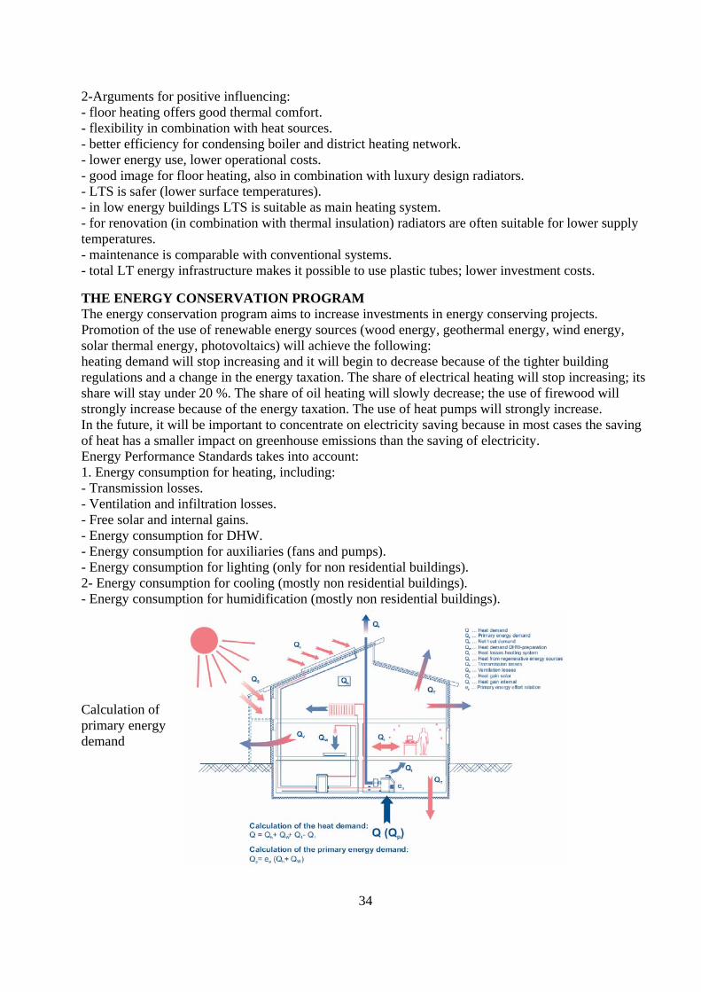
34
2-Arguments for positive influencing: - floor heating offers good thermal comfort. - flexibility in combination with heat sources. - better efficiency for condensing boiler and district heating network. - lower energy use, lower operational costs. - good image for floor heating, also in combination with luxury design radiators. - LTS is safer (lower surface temperatures). - in low energy buildings LTS is suitable as main heating system. - for renovation (in combination with thermal insulation) radiators are often suitable for lower supply temperatures. - maintenance is comparable with conventional systems. - total LT energy infrastructure makes it possible to use plastic tubes; lower investment costs. THE ENERGY CONSERVATION PROGRAM The energy conservation program aims to increase investments in energy conserving projects. Promotion of the use of renewable energy sources (wood energy, geothermal energy, wind energy, solar thermal energy, photovoltaics) will achieve the following: heating demand will stop increasing and it will begin to decrease because of the tighter building regulations and a change in the energy taxation. The share of electrical heating will stop increasing; its share will stay under 20 %. The share of oil heating will slowly decrease; the use of firewood will strongly increase because of the energy taxation. The use of heat pumps will strongly increase. In the future, it will be important to concentrate on electricity saving because in most cases the saving of heat has a smaller impact on greenhouse emissions than the saving of electricity. Energy Performance Standards takes into account: 1. Energy consumption for heating, including: - Transmission losses. - Ventilation and infiltration losses. - Free solar and internal gains. - Energy consumption for DHW. - Energy consumption for auxiliaries (fans and pumps). - Energy consumption for lighting (only for non residential buildings). 2- Energy consumption for cooling (mostly non residential buildings). - Energy consumption for humidification (mostly non residential buildings). Calculation of primary energy demand

35
RECOMMENDATIONS -The review of strategies and policies in different countries shows that there is a common aim to reduce the demand of energy use in buildings. - Focus on reducing transmission losses of building envelopes. - Requirements for reducing ventilation heat losses. Ventilation heat losses are as important as transmission losses. - the quality of energy is very important , there are aims to reduce the use of electricity for heating. In Sweden it is prohibited for new buildings, -Building services systems and equipment should be developed further, taking into account their electrical efficiency. -High quality energy should not be used for heating and cooling in buildings without a thorough investigation of suitable alternatives. - Poor insulation or ventilation energy losses can usually be compensated by the use of renewables. -One should not forget that rational passive design is a prerequisite for realizing low exergy systems for the heating and cooling of buildings. CONCLUSIONS The classical exergy analysis enables to understand the cause, and to establish the true magnitude of waste and loss. Exergy analysis provides the designer with additional information on where and why the losses occur. The designer can then proceed forward and work on how to improve the thermal system. Exergy analysis can also be applied to human body to find optimal thermal conditions. Research shows that people living in houses with low temperature heating systems are very satisfied with ambient indoor air quality. 'low exergy (or LowEx) systems' are defined as heating or cooling systems that allow the use of low valued energy as the energy source. In practice, this means systems that provide heating or cooling energy at a temperature close to room temperature. These systems use energy efficiently while providing a comfortable indoor climate. They should be widely implemented now in order to create possibility to use sustainable energy sources in the near future. Low temperature heat distribution systems have an operating life of at least 30-40 years during which time the user benefits from the economic advantages offered by flexibility of fuel choice. The life cycle costs of a low temperature heating system are about the same as of a traditional system. Although the initial investment might be slightly higher, the system offers increased flexibility in terms of fuel choice and increased energy efficiency. For example the efficiency of solar heating.