Heather Waldeck Meghan Olson Andrea Zelisko Yao Lu Ben Sprague Missy Haehn Team Members:
32
Heather Waldeck Heather Waldeck Meghan Olson Meghan Olson Andrea Zelisko Andrea Zelisko Yao Lu Yao Lu Ben Sprague Ben Sprague Missy Haehn Missy Haehn Team Members: Team Members:
-
Upload
augusta-french -
Category
Documents
-
view
215 -
download
2
Transcript of Heather Waldeck Meghan Olson Andrea Zelisko Yao Lu Ben Sprague Missy Haehn Team Members:

Heather Waldeck Heather Waldeck Meghan Olson Meghan Olson Andrea ZeliskoAndrea Zelisko
Yao LuYao LuBen SpragueBen SpragueMissy HaehnMissy Haehn
Team Members:Team Members:

Advisor:Advisor:
Professor John Professor John WebsterWebster
Client:Client:
Matthew I. Banks, Ph.D.Matthew I. Banks, Ph.D.Department of Department of AnesthesiologyAnesthesiologyUniversity of Wisconsin University of Wisconsin

To develop a lightweight device to To develop a lightweight device to measure the position of a mouse head. measure the position of a mouse head. The device would be used during an The device would be used during an experiment and must not interfere with experiment and must not interfere with the testing.the testing.

•Sound waves elicit vibrations in cochleaSound waves elicit vibrations in cochlea
•The basilar membrane transfers sound The basilar membrane transfers sound waves into neural signals.waves into neural signals.
•If sound is repeated we learn the If sound is repeated we learn the frequency pattern and can recognize that frequency pattern and can recognize that soundsound
•Sound location determined from wave Sound location determined from wave phase and time differences.phase and time differences.

•Different sounds trigger different neural pathways.Different sounds trigger different neural pathways.
•Neural pathways are crucial in sound perception.Neural pathways are crucial in sound perception.
• GABAA receptors facilitate inhibition of neural GABAA receptors facilitate inhibition of neural excitation.excitation.
• Inhibitory activities play important role in Inhibitory activities play important role in perception and cognition of auditory stimuli.perception and cognition of auditory stimuli.

• Our client studies perception and cognition of Our client studies perception and cognition of auditory system in mice.auditory system in mice.
•Measures brain waves of mice in response to Measures brain waves of mice in response to sound stimuli.sound stimuli.
• Position and orientation of head relative to Position and orientation of head relative to speaker will affect brain activityspeaker will affect brain activity
• Specifically studying the effects of drugs on Specifically studying the effects of drugs on perception and cognition in miceperception and cognition in mice

• <$5,000
• Does not interfere with current equipment
• <1 gram on head
• Does not pose danger to mouse and testers
• Must work with in conditions of cage
• Easy to use (minimal calibration)
• < 1 cm x 1 cm

Presenters: Meghan Olson
Ben Sprague
Overview
•Design Options
•Optical
•Ultrasonic
•Magnetic
•Design Matrix
•Proposed Design

•Polaris Development Kit
•2 wireless infrared light emitters placed strategically placed on head
•Infrared light sensor placed outside cage, within line of sight of entire cage
•Sensor connected to computer, interpreting signal with designed software

•Easy system to use with well developed software
•Little adjustment of product to make it work in this design setting
•Wireless emitters of light, so less restricting on subject
•Expensive in comparison to other designs
•Require line of sight between emitters and sensor at all times
•Continual improvements and updates to technology continuing
• Two transmitters on head, at least three receivers around cage
• Voltage or time measured at receivers
• Can calculate distance from receivers
• Can calculate angle from two signals of the head

• Operates in a reasonable frequency (40 kHz)
• Cost efficient
• Feasible
• Gives position and orientation
• Interference from bouncing signals
• Not light enough
• May be difficult to process signals

• Magnetic fields will produce current in wire
• Use Honeywell sensors
• ± 90° and ± 45 °
• ~$5 each
• Have sensor grid underneath cage
• Two or Three small magnets on the mouse head
• Measure magnitude of voltage
• Need amplifier circuits

• Lightweight
• Cost effective
• Easy to use
• No wires on mouse
• May affect/affected by existing instrumentation
• Positioning algorithm
• Affect brain sensors or mouse?
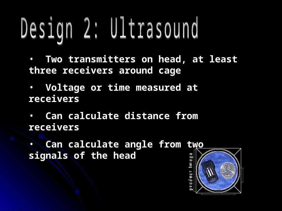
Design OptionsDesign Options FeasibilityFeasibility Size/WeightSize/Weight CostCost Ease of UseEase of Use
UltrasonicUltrasonic 33 11 22 11
MagneticMagnetic 11 22 11 33
InfraredInfrared 33 33 22 22
TotalTotal
77
77
1010

• How many sensors?
• Where to position sensors and magnets (how far apart?)
• How does mouse movement affect voltage readings
• How to connect to computer
• Parallel Port
• Interface

•NDI. http://www.ndigital.com/polaris.html. October 2nd, 2003
•Mass – Air/ Ultrasonic. http://www.massa.com/air_products.htm. September 29, 2003.
• Honeywell SSEC. http://www.ssec.honeywell.com/magnetic/products.html. October 4, 2003.

Design Team 2Design Team 2PresentersPresenters
Missy HaehnMissy HaehnHeather WaldeckHeather Waldeck
Outline of Design OptionsOutline of Design OptionsMagnetic SphereMagnetic SphereLEDLEDElectrical PotentialElectrical Potential

Option 1: Magnetic BallOption 1: Magnetic Ball How it worksHow it works
Sphere with magnet is Sphere with magnet is on mouse headon mouse head
Lengthening and Lengthening and direction of force direction of force correlates with positioncorrelates with position
Ability to measure Ability to measure orientationorientation
DisadvantagesDisadvantages Calibration neededCalibration needed WeightWeight

Option 2: LEDOption 2: LED
How it works:How it works: Sound for exp. is emitted and the LED Sound for exp. is emitted and the LED
pulsespulses Pulse detected by light sensors (receiver)Pulse detected by light sensors (receiver) Position determined by sensorsPosition determined by sensors Voltage output generated for analyzationVoltage output generated for analyzation
Disadvantages:Disadvantages: Precise, but 2-D positionPrecise, but 2-D position Light sensors must Light sensors must
surround entire cagesurround entire cage

Option 3: Electric PotentialOption 3: Electric Potential How it worksHow it works
3 conducting spheres with 3 conducting spheres with specific charges and positions specific charges and positions above mouse headabove mouse head
Measure electric potentialMeasure electric potential V = ke( q1/r1 + q2/r2 + q3/r3 ) V = ke( q1/r1 + q2/r2 + q3/r3 )
Ability to measure head Ability to measure head orientationorientation
DisadvantagesDisadvantages InterferenceInterference Need additional known variableNeed additional known variable

Evaluation GridEvaluation GridMagnetic Magnetic
BallBall LEDLED Electric Electric PotentialPotential
WeightWeight Very HeavyVery Heavy LightLight ModerateModerate
PrecisionPrecision 3-D3-D 2-D2-D 3-D3-D
CostCost ModerateModerate HighHigh LowLow
InterferenceInterference Moderately Moderately LowLow NoneNone HighHigh
SafetySafety Moderately Moderately UnsafeUnsafe Very safeVery safe
Moderately Moderately
safesafe
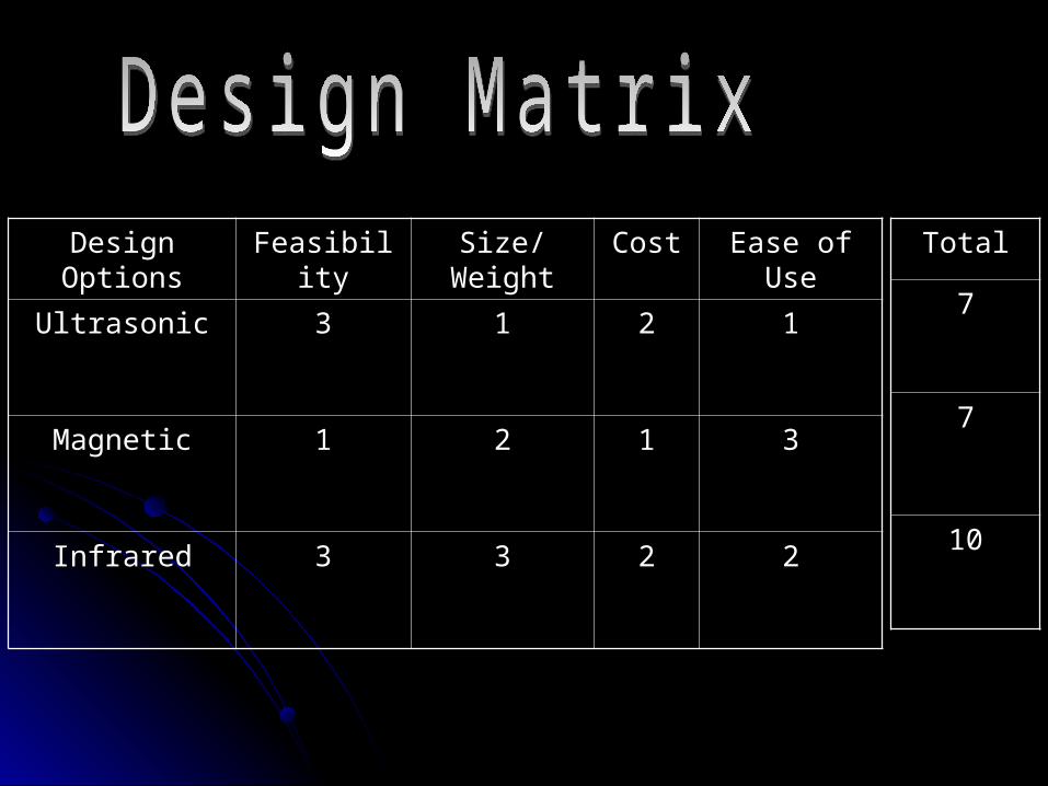
Final Choice: Final Choice: Electric Potential + LED Electric Potential + LED Magnetic Ball design too heavyMagnetic Ball design too heavy LED design only produced 2-D positionLED design only produced 2-D position Electric Potential design had too many unknowns Electric Potential design had too many unknowns
to solveto solve
Solution: Combine Electric Potential with Solution: Combine Electric Potential with LEDLED 3 different known charges and an LED on mouse’s 3 different known charges and an LED on mouse’s
headhead Voltmeter and light sensors together determine Voltmeter and light sensors together determine
position and orientation of mouse’s headposition and orientation of mouse’s head Two methods of sensing result in accurate, 3-D Two methods of sensing result in accurate, 3-D
datadata

Future WorkFuture Work
Reduce interferenceReduce interference InsulationInsulation
Investigate and test sensorsInvestigate and test sensorsVoltmeter and lightVoltmeter and light
Determine appropriate chargesDetermine appropriate chargesCreate appropriate electrical potentialCreate appropriate electrical potential
Find way to correlate different Find way to correlate different voltagesvoltagesSoftwareSoftware

Design Team 3Design Team 3
PresentersPresentersYao LuYao LuAndrea ZeliskoAndrea Zelisko
Design OverviewDesign OverviewAcoustic (Ultrasound) TrackingAcoustic (Ultrasound) TrackingOptical TrackingOptical TrackingMagnetic TrackingMagnetic Tracking

Acoustic (Ultrasound) TrackingAcoustic (Ultrasound) Tracking
Direct MeasurementDirect Measurement Time-of-flightTime-of-flight
Two transmittersTwo transmitters Different frequencyDifferent frequency
Three receivers for Three receivers for each transmittereach transmitter
(Auer et al)

Optical TrackingOptical Tracking
Four passive LEDsFour passive LEDsCamera in fixed locationCamera in fixed locationExternal Infrared sourceExternal Infrared sourceContinuous tracking (position, orientation)Continuous tracking (position, orientation)
External Infrared Source
Illumination Mouse’s Head with four
passive LEDs
Reflection Camera
(Baratoff andBlanksteen)

Magnetic TrackingMagnetic Tracking
Source composed of 3 coils of wire Source composed of 3 coils of wire perpendicular to each other.perpendicular to each other.
Magnetic field due to coils.Magnetic field due to coils. Sensor detects strength of field.Sensor detects strength of field.
(“Sensing in VR”)

Design MatrixDesign Matrix
Acoustic(Ultrasound)
Optical Electro-magnetic
Interference Sources
3 2 1
Ease to Manufacture
1 3 2
Accuracy 2 3 1
weight 1 3 2
Interference with Data
2 3 1
Overall Score 9 13 7
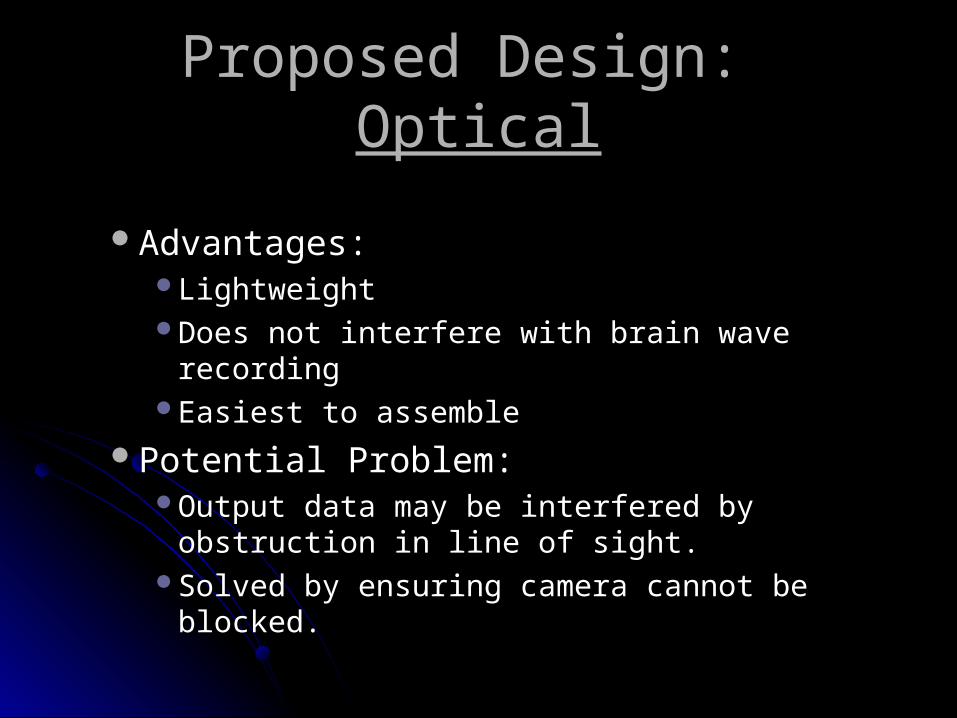
Proposed Design: Proposed Design: OpticalOptical
Advantages:Advantages:Lightweight Lightweight Does not interfere with brain wave recordingDoes not interfere with brain wave recordingEasiest to assembleEasiest to assemble
Potential Problem:Potential Problem:Output data may be interfered by obstruction in Output data may be interfered by obstruction in
line of sight.line of sight.Solved by ensuring camera cannot be blocked.Solved by ensuring camera cannot be blocked.

Future WorksFuture Works
Research and finalize the proposed designResearch and finalize the proposed designDecide on componentsDecide on componentsBuild deviceBuild deviceTest deviceTest device
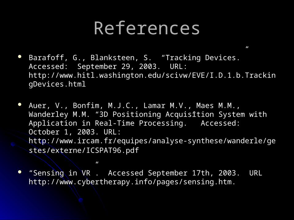
ReferencesReferences Barafoff, G., Blanksteen, S. “Tracking Devices.” Accessed: September 29, Barafoff, G., Blanksteen, S. “Tracking Devices.” Accessed: September 29,
2003. URL: 2003. URL: http://www.hitl.washington.edu/scivw/EVE/I.D.1.b.TrackingDevices.html http://www.hitl.washington.edu/scivw/EVE/I.D.1.b.TrackingDevices.html
Auer, V., Bonfim, M.J.C., Lamar M.V., Maes M.M., Wanderley M.M. “3D Auer, V., Bonfim, M.J.C., Lamar M.V., Maes M.M., Wanderley M.M. “3D Positioning Acquisition System with Application in Real-Time Processing.” Positioning Acquisition System with Application in Real-Time Processing.” Accessed: October 1, 2003. URL: http://www.ircam.fr/equipes/analyse-Accessed: October 1, 2003. URL: http://www.ircam.fr/equipes/analyse-synthese/wanderle/gestes/externe/ICSPAT96.pdfsynthese/wanderle/gestes/externe/ICSPAT96.pdf
““Sensing in VR”. Accessed September 17th, 2003. URLSensing in VR”. Accessed September 17th, 2003. URLhttp://www.cybertherapy.info/pages/sensing.htm.http://www.cybertherapy.info/pages/sensing.htm.