Heaters BAND AND NLE - Chromalox, Inc. Band Heaters • Thin, Efficient Heater ... A mica core...
4
Components A-83 BAND AND NOZZLE Mica Band Heaters • Thin, Efficient Heater • Up to 800˚F Max. Sheath Temperature • MB-1, MB-2 Description A mica core produces a thin, efficient heater. Heat from the precisely wound resistance element is quickly transferred to the working surface for fast heat-up and response. Mica provides excellent dielectric strength and heat transfer capability for long heater life. The mica core is encased in a continuous corro- sion resistant sheath and formed. All full mica band heaters are designed with closed ends to protect against contamination. Maximum sheath temperature is 800°F. Type A – Usual design for nozzle heating ap- plications. 12” leads are standard. Fig. 3 – Single conductor metal braid over lead wire. Offers most practical solution to abrasion problem. 12” braid with 14” overall length leads are standard. Fig. 4 – Standard lead wires exiting 180° from gap. Fig. 5 – Leads exit at right angle to sheath 5⁄8” from gap. 12” lead wire in 3” long sleeving is standard. Specify alternate position. Fig. 6 – Flexible armor cable is the best solu- tion to lead abrasion problems. 12” armor with 14” overall length leads are standard. Specify alternate position. Fig. 16 – Double conductor metal braid over lead wires at same position as Fig. 5. 12” braid with 14” overall length leads are standard. Specify alternate position. Fig. 7 – Double conductor metal braid exiting from edge 180° from gap.
-
Upload
nguyenxuyen -
Category
Documents
-
view
221 -
download
5
Transcript of Heaters BAND AND NLE - Chromalox, Inc. Band Heaters • Thin, Efficient Heater ... A mica core...

Components
A-83
BAN
D A
ND
NO
ZZLEMica Band
Heaters
• Thin,EfficientHeater
• Upto800˚FMax.SheathTemperature
• MB-1,MB-2
Description
A mica core produces a thin, efficient heater. Heat from the precisely wound resistance element is quickly transferred to the working surface for fast heat-up and response. Mica provides excellent dielectric strength and heat transfer capability for long heater life. The mica core is encased in a continuous corro-sion resistant sheath and formed. All full mica band heaters are designed with closed ends to protect against contamination. Maximum sheath temperature is 800°F.
Type A – Usual design for nozzle heating ap-plications. 12” leads are standard.
Fig. 3 – Single conductor metal braid over lead wire. Offers most practical solution to abrasion problem. 12” braid with 14” overall length leads are standard.
Fig. 4 – Standard lead wires exiting 180° from gap.
Fig. 5 – Leads exit at right angle to sheath 5⁄8” from gap. 12” lead wire in 3” long sleeving is standard. Specify alternate position.
Fig. 6 – Flexible armor cable is the best solu-tion to lead abrasion problems. 12” armor with 14” overall length leads are standard. Specify alternate position.
Fig. 16 – Double conductor metal braid over lead wires at same position as Fig. 5. 12” braid with 14” overall length leads are standard. Specify alternate position.
Fig. 7 – Double conductor metal braid exiting from edge 180° from gap.

Components
A-84
Mica Band Heaters(cont’d.)
Screw Terminals
Fig. T1 – 10-24 Thread requires 15⁄16” clear-ance from cylinder.
Fig. T2 – Standard position over 21⁄2”wide. 10-24 Thread.
Fig. T3 – Standard with terminal box. 10-24 Thread.
Fig. B1 – 10-24 thread requires 1⁄2” clearance from cylinder.
Special Features
Fig. 12 Hinged Half-Band — convenient where two piece heaters are required. Shown with mounting flange and T3 screw terminals. Available with any termination or mounting arrangement.
Fig. 14 Half Band — eases installation in dif-ficult situations. Shown with T1 Terminals and by-pass straps. Available with any termination or mounting arrangement
Fig. 15 – Probe holes and cut-outs — specify location in degrees from center of gap and size or provide drawing. Often a larger gap (standard gap is 1⁄4” - 1”) will serve the same purpose.
Fig. 17 – Splitcase — Allows heater to be opened one time for mounting. Available with any termination or mounting arrangement.
Components
A-85
BAN
D A
ND
NO
ZZLEMica Band
Heaters(cont’d.)
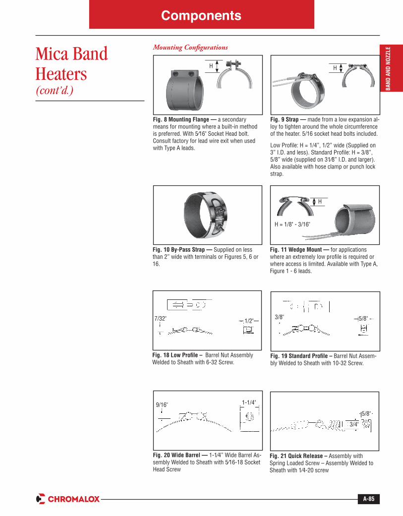
Mounting Configurations
Fig. 9 Strap — made from a low expansion al-loy to tighten around the whole circumference of the heater. 5/16 socket head bolts included.
Low Profile: H = 1/4”, 1/2” wide (Supplied on 3” I.D. and less). Standard Profile: H = 3/8”, 5/8” wide (supplied on 31⁄8” I.D. and larger). Also available with hose clamp or punch lock strap.
H
Fig. 8 Mounting Flange — a secondary means for mounting where a built-in method is preferred. With 5⁄16" Socket Head bolt. Consult factory for lead wire exit when used with Type A leads.
H
Fig. 10 By-Pass Strap — Supplied on less than 2” wide with terminals or Figures 5, 6 or 16.
Fig. 11 Wedge Mount — for applications where an extremely low profile is required or where access is limited. Available with Type A, Figure 1 - 6 leads.
H
H = 1/8" - 3/16"
Fig. 18 Low Profile – Barrel Nut Assembly Welded to Sheath with 6-32 Screw.
Fig. 20 Wide Barrel — 1-1⁄4” Wide Barrel As-sembly Welded to Sheath with 5⁄16-18 Socket Head Screw
1-1/4"9/16"
Fig. 19 Standard Profile – Barrel Nut Assem-bly Welded to Sheath with 10-32 Screw.
Fig. 21 Quick Release – Assembly with Spring Loaded Screw – Assembly Welded to Sheath with 1⁄4-20 screw
5/8"
3/4"
7/32" 1/2" 5/8"3/8"

Components
A-86
Mica Band Heaters(cont’d.)
Terminal Protection
Terminal Box Cover – 2” H x11⁄2” W x 2” L. Also available in a 2-1⁄4” H x 21⁄16” W x 4-1⁄2” L terminal box for larger clearance to terminals.
Ceramic Terminal Cover – 7⁄8” high x 3⁄4” O.D. for 10-24 thread.
Plugs
Fig. 7P – Plug can be attached to any lead configuration.
Fig. 110 – Dimensions (In.)3-1⁄2" H x 15⁄16" L x 2-15⁄16" W
European Style High Temperature Plug (250 Volt Maximum)
Fig. 115 – Dimensions (In.)1-3⁄8" H x 3-7⁄16" L x 1-7⁄8" W
Fig. GQ8 – Receptacle
Plug Terminations
U.L. Listed Plugs are available attached to heater by cord, cable or leads. Matching receptacles are also available.
Manufacturer NumberChromalox
PCNNEMARef.
Leviton 515PA PC4326-27 5-15PEagle 2866 PC4326-281 6-15PArrowhart 4771 PC4326-50 L7-15RLeviton 5444 PC4326-29 5-20PHubbell 2311 PC4326-25 L5-20PEagle 2364 PC4326-26E L6-20P
Additional Variations
• Three terminal or lead, dual voltage, three phase or ground
• Appliance pin terminals
• Full length fiberglass sleeving
• Rectangular or segment band heaters – provide drawing
• Outside diameter design for internally heating cylinder
• Stainless steel or Monel sheath for use in corrosive atmosphere
• Metric Sizes