Heat Transmission HVAC CNST 305 Environmental Systems 1 Dr. Berryman.
21
Heat Transmission HVAC CNST 305 Environmental Systems 1 Dr. Berryman
-
date post
19-Dec-2015 -
Category
Documents
-
view
222 -
download
3
Transcript of Heat Transmission HVAC CNST 305 Environmental Systems 1 Dr. Berryman.
Heat Transmission
HVAC
CNST 305 Environmental Systems 1Dr. Berryman
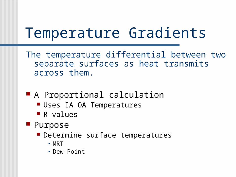
Temperature GradientsThe temperature differential between two
separate surfaces as heat transmits across them.
A Proportional calculation Uses IA OA Temperatures R values
Purpose Determine surface temperatures
• MRT• Dew Point

Develop Thermal Resistant Values
AL Siding
¼” USB
R19 Batt
3/8” Gyp Board
IA Air Film
OA Air Film
21.37RTOTAL =
0.17
0.61
0.66
19.00
0.32
0.61
R values
Wall Section
Note: This is an actual construction in Grand Island
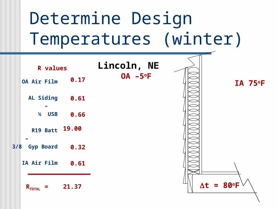
Determine Design Temperatures (winter)
AL Siding
¼” USB
R19 Batt
3/8” Gyp Board
IA Air Film
OA Air Film 0.17
0.61
0.66
19.00
0.32
21.37
0.61
RTOTAL =
R values Lincoln, NEOA –5oF
IA 75oF
t = 80oF
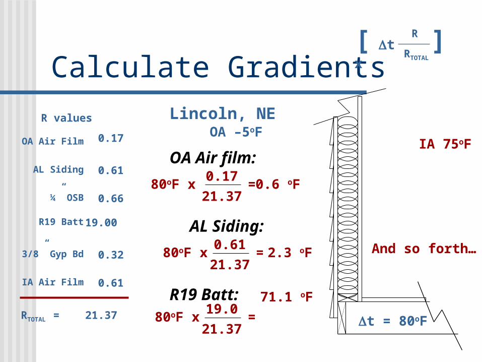
Calculate GradientsLincoln, NE
OA –5oFIA 75oF
t = 80oF
OA Air film:
80oF x0.17
21.37=0.6 oF
0.61
21.37=
AL Siding:
80oF x 2.3 oF
19.0
21.37=80oF x
71.1 oF R19 Batt:
AL Siding
¼” OSB
R19 Batt
3/8” Gyp Bd
IA Air Film
OA Air Film 0.17
0.61
0.66
19.00
0.32
21.37
0.61
RTOTAL =
R values
And so forth…
[ t x R
RTOTAL
]
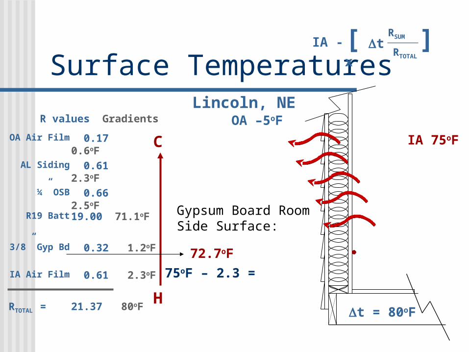
Surface TemperaturesLincoln, NE
OA –5oF
t = 80oF
IA 75oF
AL Siding
¼” OSB
R19 Batt
3/8” Gyp Bd
IA Air Film
OA Air Film 0.17 0.6oF
0.61 2.3oF
0.66 2.5oF
19.00 71.1oF
0.32 1.2oF
21.37 80oF
0.61 2.3oF
RTOTAL =
R values Gradients
H
C
Gypsum Board Room Side Surface:
75oF – 2.3 =
72.7oF
[ t x RSUM
RTOTAL
]IA -

Surface Temps (cont.)Lincoln, NE
OA –5oF
t = 80oF
AL Siding
¼” OSB
R19 Batt
3/8” Gyp Bd
IA Air Film
OA Air Film 0.17 0.6oF
0.61 2.3oF
0.66 2.5oF
19.00 71.1oF
0.32 1.2oF
21.37 80oF
0.61 2.3oF
RTOTAL =
R values Gradients
H
C
Gypsum Board Wall Cavity Surface:
75oF – (2.3+1.2) =71.5oF
IA 75oF
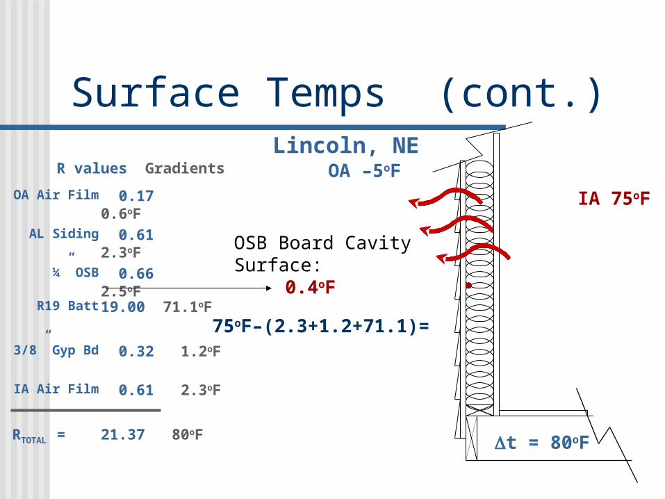
Surface Temps (cont.)Lincoln, NE
OA –5oF
t = 80oF
AL Siding
¼” OSB
R19 Batt
3/8” Gyp Bd
IA Air Film
OA Air Film 0.17 0.6oF
0.61 2.3oF
0.66 2.5oF
19.00 71.1oF
0.32 1.2oF
21.37 80oF
0.61 2.3oF
RTOTAL =
R values Gradients
OSB Board Cavity Surface:
75oF–(2.3+1.2+71.1)=
0.4oF
IA 75oF

Heat Transmission
-20o
10o
0o
-10o
20o
30o
40o
50o
60o
70o
80oF
TemperatureLincoln, NE
OA –5oF
IA 75oF
AL Siding
¼” OSB
R19 Batt
3/8” Gyp Bd
IA Air Film
OA Air Film 0.17 0.6oF
0.61 2.3oF
0.66 2.5oF
19.00 71.1oF
0.32 1.2oF
21.37 80oF
0.61 2.3oF
RTOTAL =
R values Gradients
H
C
OSB Cav Side 0.4oF
Gyp Cav Side 71.5oF
OSB OA Side -2.1oF
Siding Surface -4.4oF
Gyp Rm Side 72.7oF
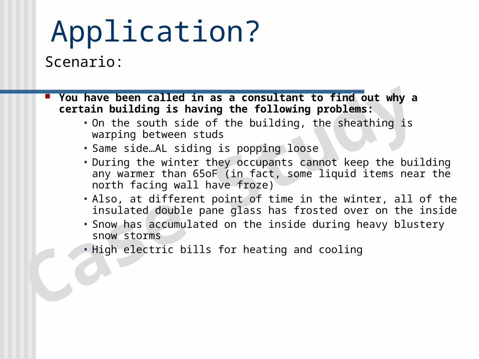
Application?
Case StudyScenario:
You have been called in as a consultant to find out why a certain building is having the following problems:
• On the south side of the building, the sheathing is warping between studs
• Same side…AL siding is popping loose• During the winter they occupants cannot keep the building
any warmer than 65oF (in fact, some liquid items near the north facing wall have froze)
• Also, at different point of time in the winter, all of the insulated double pane glass has frosted over on the inside
• Snow has accumulated on the inside during heavy blustery snow storms
• High electric bills for heating and cooling
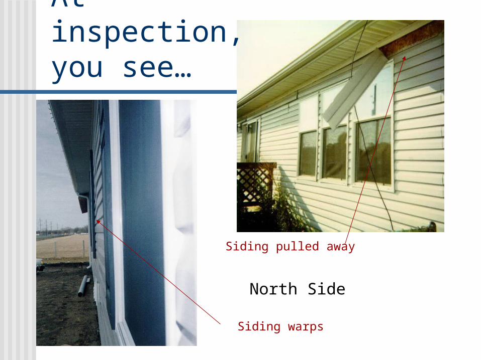
At inspection, you see…
North Side
Siding warps
Siding pulled away

You see…
South Side
Siding warps in and out every 16”
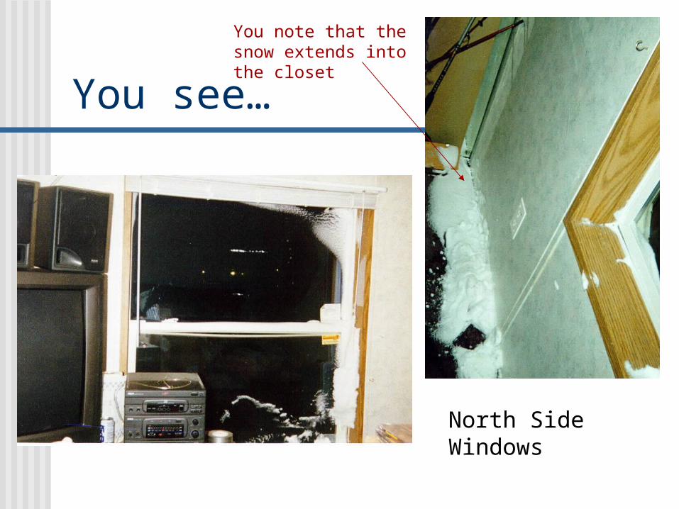
You see…
North Side Windows
You note that the snow extends into the closet
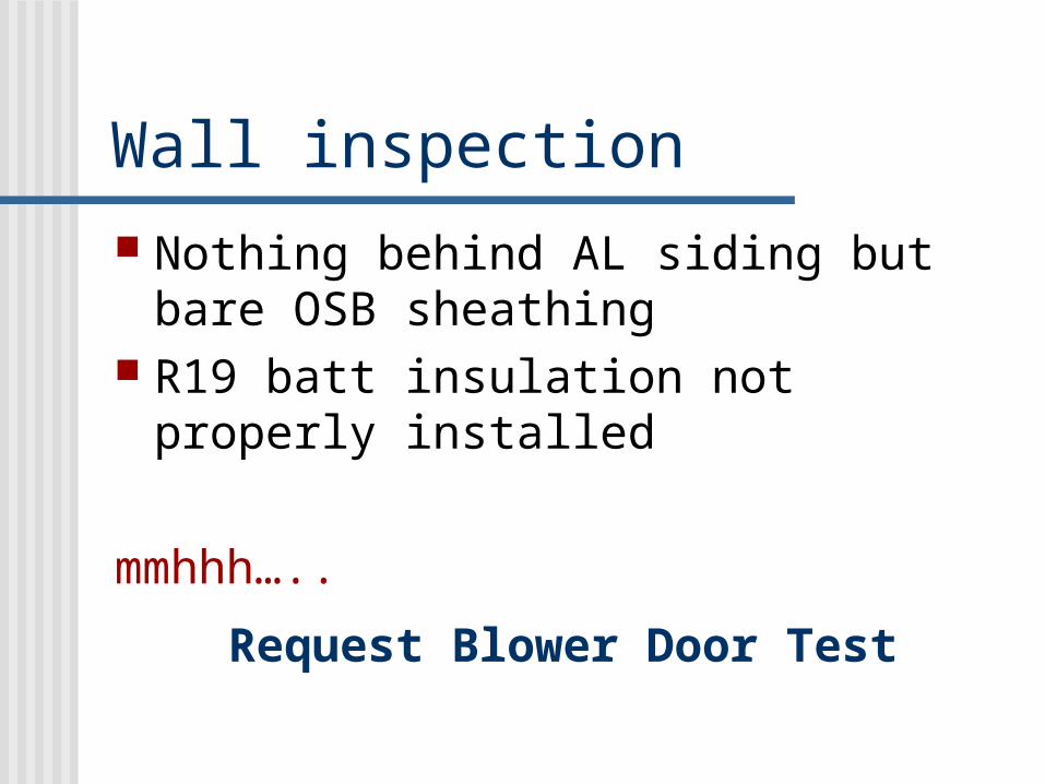
Wall inspection Nothing behind AL siding but bare
OSB sheathing R19 batt insulation not properly
installed
mmhhh…..
Request Blower Door Test
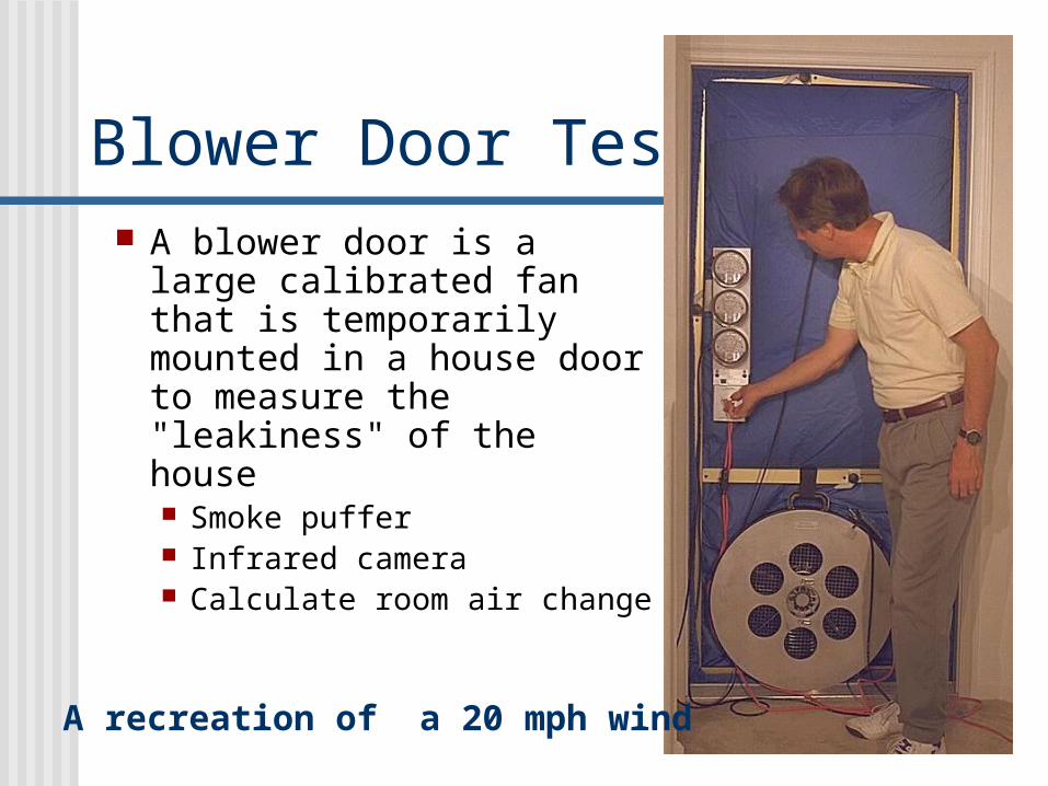
Blower Door Test A blower door is a large
calibrated fan that is temporarily mounted in a house door to measure the "leakiness" of the house Smoke puffer Infrared camera Calculate room air change
A recreation of a 20 mph wind

You discover… Air leaks
Around doors and windows Behind plumbing fixtures Between sill plate and floor
Infrared Shows air infiltrating around each insulation batt
and at sill plate Calculations from pressure differentials
133 CFM infiltration (ASHRAE recommends 10 cfm for residential)
35 CFM ventilation
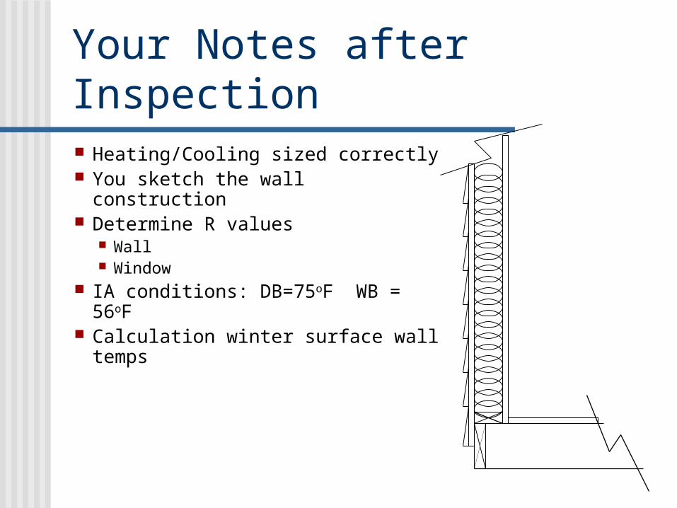
Your Notes after Inspection Heating/Cooling sized correctly You sketch the wall construction Determine R values
Wall Window
IA conditions: DB=75oF WB = 56oF
Calculation winter surface wall temps

What next?
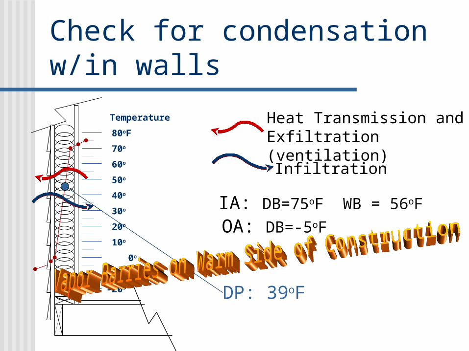
Check for condensation w/in walls
-20o
10o
0o
-10o
20o
30o
40o
50o
60o
70o
80oF
Temperature Heat Transmission and Exfiltration (ventilation)
Infiltration
IA: DB=75oF WB = 56oF
OA: DB=-5oF
DP: 39oF
DS Glass
Air Space
DS Glass
IA Air Film
OA Air Film 0.17
0.01
1.00
0.01
0.61
1.8RTOTAL =
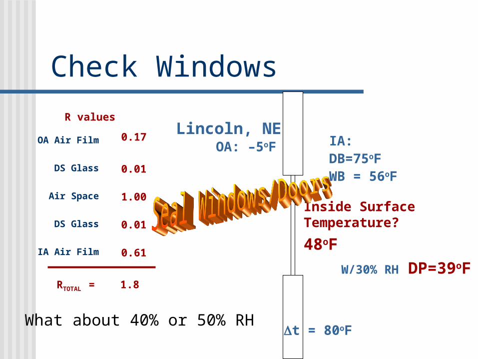
R valuesLincoln, NE
OA: –5oF
t = 80oF
IA:DB=75oF WB = 56oF
Check Windows
Inside Surface Temperature?
48oF
W/30% RH DP=39oF
What about 40% or 50% RH
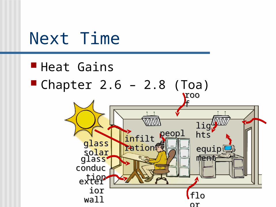
Next Time Heat Gains Chapter 2.6 – 2.8 (Toa)
roofroof
lightslights
equipmeequipmentnt
floorfloor
exteriorexteriorwallwall
glass solarglass solar
glassglassconductioconductio
nn
infiltrationinfiltrationpeoplepeople