Heat Transfer - Principles & Equipment
13
8/31/2015 HEAT TRANSFER PRINCIPLES & EQUIPMENT http://articles.compressionjobs.com/articles/oilfield101/1856heatexchangersboilersfurnaces?tmpl=component&print=1&page= 1/13 HEAT TRANSFER PRINCIPLES & EQUIPMENT Written by Norrie Wednesday, 17 February 2010 20:47 Introduction Heat energy can be transferred in three ways. These are : 1. BY CONDUCTION 2. BY CONVECTION 3. BY RADIATION 1. HEAT TRANSFER BY CONDUCTION This kind of heat transfer can only take place in solids and is considered as the slowest form of heat transfer. Solids which allow the flow of heat are referred to as ' Conductors ' and, those which do not conduct heat are called ' Insulators ' All metals and carbon will conduct heat some metals have a high heat conductivity while others are slower. Conduction is the process of heat transfer by 'Collision of Molecules' in a substance. As temperature increases, molecules move faster and strike other molecules harder and more often. An example of this is: when an iron bar is held at one end with the other end in a fire, the molecular motion at the hot end increases and the heat gradually travels along the bar by the increase in the motion and collision of molecules, until it can be felt by the hand. ( See Figure 18 ) Examples of insulators are, wood, plastics, air or gases and lagging such as fibre glass, cork and asbestos ..etc. Some FACTORS which affect the rate of heat transfer by conduction are : 1. The Thickness of the Material. 2. The Temperature Difference between the two sides of the solid being heated ( length of heat path ). 3. The Conductivity of the Material. 4. The Surface Area. 2. HEAT TRANSFER BY CONVECTION Convection takes place in fluids. As a fluid is heated, the molecules increase in motion and the fluid begins to expand molecules move further apart. This gives a decrease in density which causes the hotter fluid to rise and the cool fluid to fall, setting up a circulation within the fluid. The heat energy is gradually increased throughout the fluid. This method of heat transfer is seen in the use of Space Heating and in heat distribution in a furnace. Convection can
description
Design
Transcript of Heat Transfer - Principles & Equipment
8/31/2015 HEAT TRANSFER PRINCIPLES & EQUIPMENT
http://articles.compressionjobs.com/articles/oilfield101/1856heatexchangersboilersfurnaces?tmpl=component&print=1&page= 1/13
HEAT TRANSFER PRINCIPLES & EQUIPMENTWritten by Norrie
Wednesday, 17 February 2010 20:47
Introduction
Heat energy can be transferred in three ways. These are :
1. BY CONDUCTION2. BY CONVECTION3. BY RADIATION
1. HEAT TRANSFER BY CONDUCTION
This kind of heat transfer can only take place in solids and is considered as the slowest form of heat transfer. Solidswhich allow the flow of heat are referred to as ' Conductors ' and, those which do not conduct heat are called 'Insulators '
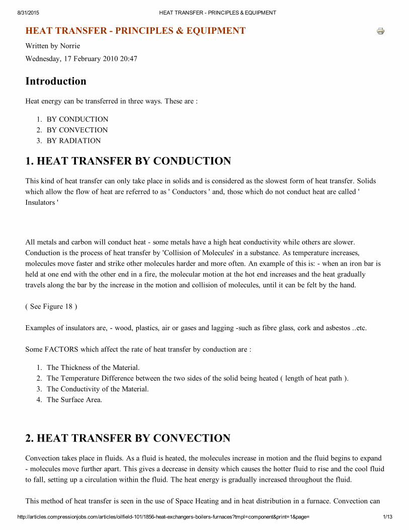
All metals and carbon will conduct heat some metals have a high heat conductivity while others are slower.Conduction is the process of heat transfer by 'Collision of Molecules' in a substance. As temperature increases,molecules move faster and strike other molecules harder and more often. An example of this is: when an iron bar isheld at one end with the other end in a fire, the molecular motion at the hot end increases and the heat graduallytravels along the bar by the increase in the motion and collision of molecules, until it can be felt by the hand.
( See Figure 18 )
Examples of insulators are, wood, plastics, air or gases and lagging such as fibre glass, cork and asbestos ..etc.
Some FACTORS which affect the rate of heat transfer by conduction are :
1. The Thickness of the Material.2. The Temperature Difference between the two sides of the solid being heated ( length of heat path ).3. The Conductivity of the Material.4. The Surface Area.
2. HEAT TRANSFER BY CONVECTION
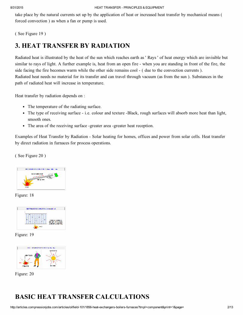
Convection takes place in fluids. As a fluid is heated, the molecules increase in motion and the fluid begins to expand molecules move further apart. This gives a decrease in density which causes the hotter fluid to rise and the cool fluidto fall, setting up a circulation within the fluid. The heat energy is gradually increased throughout the fluid.
This method of heat transfer is seen in the use of Space Heating and in heat distribution in a furnace. Convection can
8/31/2015 HEAT TRANSFER PRINCIPLES & EQUIPMENT
http://articles.compressionjobs.com/articles/oilfield101/1856heatexchangersboilersfurnaces?tmpl=component&print=1&page= 2/13
take place by the natural currents set up by the application of heat or increased heat transfer by mechanical means (forced convection ) as when a fan or pump is used.
( See Figure 19 )
3. HEAT TRANSFER BY RADIATION
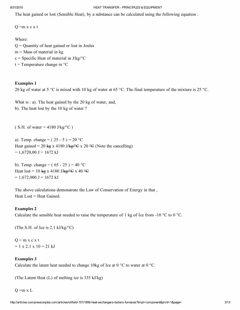
Radiated heat is illustrated by the heat of the sun which reaches earth as ' Rays ' of heat energy which are invisible butsimilar to rays of light. A further example is, heat from an open fire when you are standing in front of the fire, theside facing the fire becomes warm while the other side remains cool ( due to the convection currents ). Radiated heat needs no material for its transfer and can travel through vacuum (as from the sun ). Substances in thepath of radiated heat will increase in temperature.
Heat transfer by radiation depends on :
The temperature of the radiating surface.The type of receiving surface i.e. colour and texture Black, rough surfaces will absorb more heat than light,smooth ones.The area of the receiving surface greater area greater heat reception.
Examples of Heat Transfer by Radiation Solar heating for homes, offices and power from solar cells. Heat transferby direct radiation in furnaces for process operations.
( See Figure 20 )
Figure: 18
Figure: 19
Figure: 20
BASIC HEAT TRANSFER CALCULATIONS
8/31/2015 HEAT TRANSFER PRINCIPLES & EQUIPMENT
http://articles.compressionjobs.com/articles/oilfield101/1856heatexchangersboilersfurnaces?tmpl=component&print=1&page= 3/13
The heat gained or lost (Sensible Heat), by a substance can be calculated using the following equation :
Q =m x c x t
Where: Q = Quantity of heat gained or lost in Joules m = Mass of material in kg c = Specific Heat of material in J/kg/°C t = Temperature change in °C
Examples 1 20 kg of water at 5 °C is mixed with 10 kg of water at 65 °C. The final temperature of the mixture is 25 °C.
What is : a). The heat gained by the 20 kg of water, and, b). The heat lost by the 10 kg of water ?
( S.H. of water = 4180 J/kg/°C )
a). Temp. change = ( 25 5 ) = 20 °C Heat gained = 20 kg x 4180 J/kg/°C x 20 °C (Note the cancelling) = 1,6720,00 J = 1672 kJ
b). Temp. change = ( 65 25 ) = 40 °C Heat lost = 10 kg x 4180 J/kg/°C x 40 °C= 1,672,000 J = 1672 kJ
The above calculations demonstrate the Law of Conservation of Energy in that ,Heat Lost = Heat Gained.
Examples 2 Calculate the sensible heat needed to raise the temperature of 1 kg of Ice from 10 °C to 0 °C.
(The S.H. of Ice is 2.1 kJ/kg/°C)
Q = m x c x t = 1 x 2.1 x 10 = 21 kJ
Examples 3Calculate the latent heat needed to change 10kg of Ice at 0 °C to water at 0 °C.
(The Latent Heat (L) of melting ice is 335 kJ/kg)
Q =m x L
8/31/2015 HEAT TRANSFER PRINCIPLES & EQUIPMENT
http://articles.compressionjobs.com/articles/oilfield101/1856heatexchangersboilersfurnaces?tmpl=component&print=1&page= 4/13
= 10 x 335 = 3350 kJ
LINEAR AND CUBICAL EXPANSION
Thermal Expansion and Contraction take place when materials are heated or cooled. These effects cause an increase ordecrease in length or volume of the material. (The only exception to this is pure water at 4 °C when it is heatedabove or cooled below 4 °C, water expands ( as does ice when cooled further).
This expansion and contraction of materials can cause large forces to be set up within materials in contact with eachother, especially metals, and in equipment containing confined liquids. As heat is added in such cases, the forces setup can cause serious damage to the equipment. In process operations for example, allowances are made for theexpansion and contraction of equipment and of the fluids contained in them.
Sometimes, the expansion and contraction of materials can be made useful. For example, the bi metallic strip or coilconsists of two different metals bonded together. As heat is applied, the two metals of the strip or coil expand atdifferent rates causing a bending or twisting motion. This is put to use in Thermostats (switches) and Rotatherms(Thermomechanical thermometers) .. etc.
COEFFICIENT OF LINEAR EXPANSION
As all materials are different, the expansion ( or contraction ) rate will be different as heat is applied (or removed).The rate of expansion or contraction is the same for each degree increase or decrease in temperature. This property ofmaterials is referred to as :
The ' COEFFICIENT of LINEAR EXPANSION '. Which is defined as:
' THE INCREASE OR DECREASE IN UNIT LENGTH OF A MATERIAL PER DEGREE CENTIGRADEINCREASE OR DECREASE IN TEMPERATURE '
The Coefficient of Linear Expansion for some metals is given below. ( Metres / °C )
Steel = 0.000012 Copper = 0.000017 Aluminium = 0.000024
The total expansion / contraction depends on the type of material, the length of the rod and the temperature increase /decrease. The change in length of a metal rod can be found by the following method :
Length change (m) = Rod length (m) x Coefficient of Expansion x Temp. change
Example : A steel rod, 10 metres long is heated from 60 °C to 160 °C. What is the length of the rod after heating ?
8/31/2015 HEAT TRANSFER PRINCIPLES & EQUIPMENT
http://articles.compressionjobs.com/articles/oilfield101/1856heatexchangersboilersfurnaces?tmpl=component&print=1&page= 5/13
Length change (m) = Rod length (m) x Coefficient of Expansion x Temp. change = 10 x 0.000012 x 100 = 0.012 metres of expansion
New rod length = 10 + 0.012 = 10.012 m.
CUBICAL EXPANSION OF SOLIDS
In the case of solids which have a definite shape, when they are heated they expand in all directions i.e. Length, Height and Width. This is known as the :
'Cubical Expansion of Solids '.
This is THREE TIMES the COEFFICIENT of LINEAR EXPANSION
Example: 1 m3 of steel is heated from 100 °C to 200 °C. What is its new volume ? = 1 + ( 100 x 0.000012 x 3 )New volume = 1.0036 m3
HEAT EXCHANGE EQUIPMENT
HEAT EXCHANGERS, BOILERS & FURNACES
INTRODUCTION
Earlier, we discussed 'Heat' and 'Temperature' and the principles of heat transfer. Heat can be transferred by threemethods: Conduction, Convection and Radiation.
(See Figures: 19, 20 & 21 illustrated earlier on Page 49)
Heat exchangers are pieces of equipment used for the exchange of heat between a hot substance and a cold substance.In the process, the hot material is cooled while the cool material is heated. This exchange of heat energy is useful inconserving fuel and cooling water requirements in process operations where large quantities of heat is to be added to,or removed from, process fluids. The various names of heat exchangers and their function, as used in industry, arelisted below.
NAMES GIVEN TO HEAT EXCHANGERS
(Note: These are 'NAMES' of NOT ' TYPES' of Exchanger).
1. PREHEATERS: As the name implies, these exchangers are used to add heat to a process stream before the main heating system (a
8/31/2015 HEAT TRANSFER PRINCIPLES & EQUIPMENT
http://articles.compressionjobs.com/articles/oilfield101/1856heatexchangersboilersfurnaces?tmpl=component&print=1&page= 6/13
furnace or boiler). At the same time, the fluid being preheated is removing heat from (cooling), the heating mediumwhich may be a hot product from a process or it may be steam. Where steam is used, it is generally condensed by theheat exchange process.
2. VAPORISERS: These are used to convert a liquid into vapour by the addition of heat, generally by superheated steam. (Other hightemperature media can also be used where steam may be difficult to produce (as in desert regions).
3.CONDENSERS:Are used to remove the latent heat from a vapour, gas or steam in order to convert it to liquid. Usually, they will thenreduce the temperature (cool) the fluid being condensed. The condensing or cooling medium may be water orrefrigerant depending upon the process.
4 COOLERS: This exchanger simply cools the process fluid by exchange of heat between water or refrigerant. Where refrigerant isused, the exchanger would be classed as a 'CHILLER'.
5. HEATERS: These are used to add heat energy to increase the temperature of a process stream by using Superheated steam, Hotoil, Other hot product streams or Burning fuel.
6.REBOILERS: Generally used to heat and partially vaporise the bottom liquid of a distillation or regeneration tower. They may besteam heated, or a 'Furnace type' or a 'Fire Tube' type. Most heat exchangers use the principle of heat transfer by'Conduction' in their operation, while furnaces and boilers use all three heat transfer principles.
Heat exchangers are generally of the 'SHELL and TUBE' construction. i.e. they consist of an outer shell which carriesone of the process streams and an inner bundle of tubes for the other stream. The external and internal construction ofan exchanger will be seen in following descriptions and diagrams.
TYPES OF HEAT EXCHANGER
(Note: Following are the 'Types' of heat exchanger used in industry and may be used for any of the purposes listedpreviously in exchanger names).
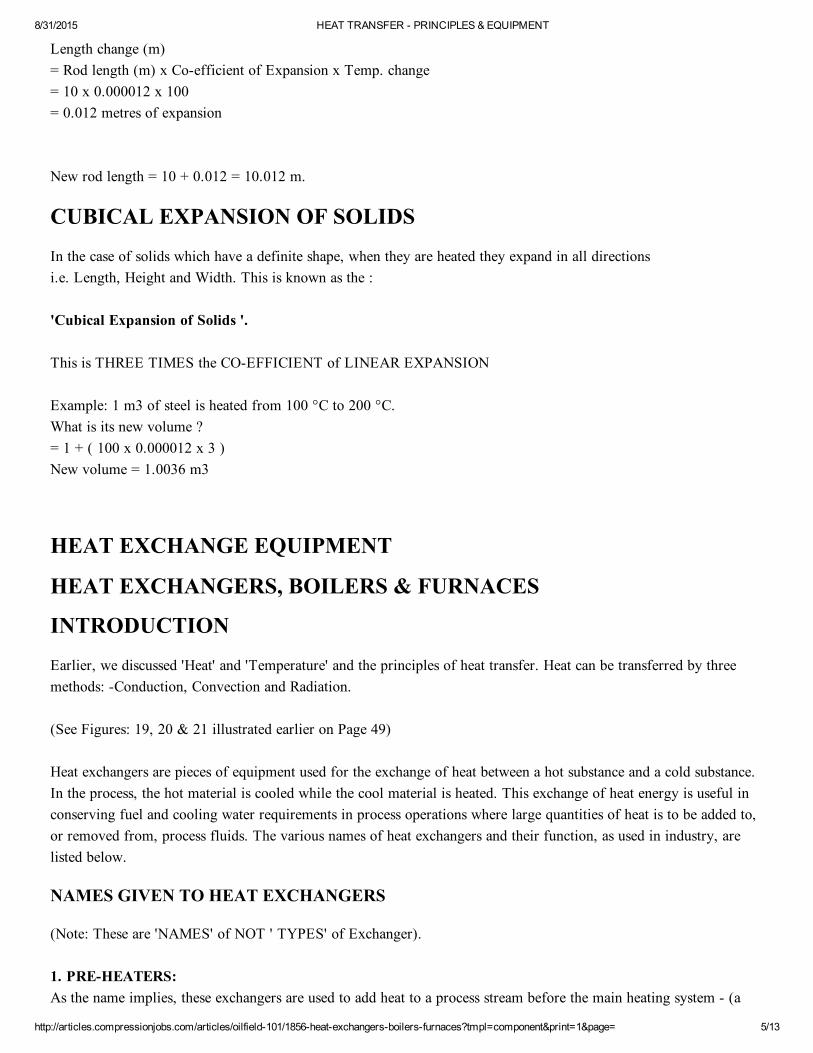
1.FIXED HEAD or FIXED TUBESHEET EXCHANGER: This is a 'Shell & Tube' type exchanger in which the tubesheet ends are fixed (rigid), with no allowance forexpansion. They are mainly used for low temperature heat exchange with low differential temperature (.T), betweenthe heat exchange fluids.
The Tubesheets, one at each end, consist of metal plates into which a bundle of tubes are fixed by 'Rolling' or'Welding'. The length of the tubes is prevented from bending by 'Transverse Baffles', each of which hold half of thebundle. These baffles also provide channels for the shellside fluid direction to constantly change and flow across thetubes a number of times.
8/31/2015 HEAT TRANSFER PRINCIPLES & EQUIPMENT
http://articles.compressionjobs.com/articles/oilfield101/1856heatexchangersboilersfurnaces?tmpl=component&print=1&page= 7/13
(See Figure: 21)
Figure: 21
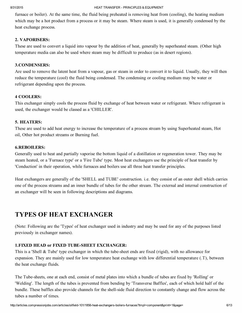
2. FLOATING HEAD EXCHANGER: In this type, also a shell & tube exchanger, one end of the tubesheet (the 'Bellend'), has provision made forexpansion and contraction of the tubes. They are generally used for high .T between the fluids.
(See Figure: 22) Figure: 22
3. THE ' U ' TUBE HEAT EXCHANGER: Here the tubes are formed into a horizontal ' U' shape and held by a single tube sheet. This gives the fluid passingthrough the tubes a 'Double Pass' through the exchanger.
(See Figure: 23)
Figure: 23
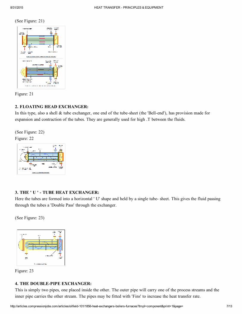
4. THE DOUBLEPIPE EXCHANGER: This is simply two pipes, one placed inside the other. The outer pipe will carry one of the process streams and theinner pipe carries the other stream. The pipes may be fitted with 'Fins' to increase the heat transfer rate.
8/31/2015 HEAT TRANSFER PRINCIPLES & EQUIPMENT
http://articles.compressionjobs.com/articles/oilfield101/1856heatexchangersboilersfurnaces?tmpl=component&print=1&page= 8/13
Figure: 24
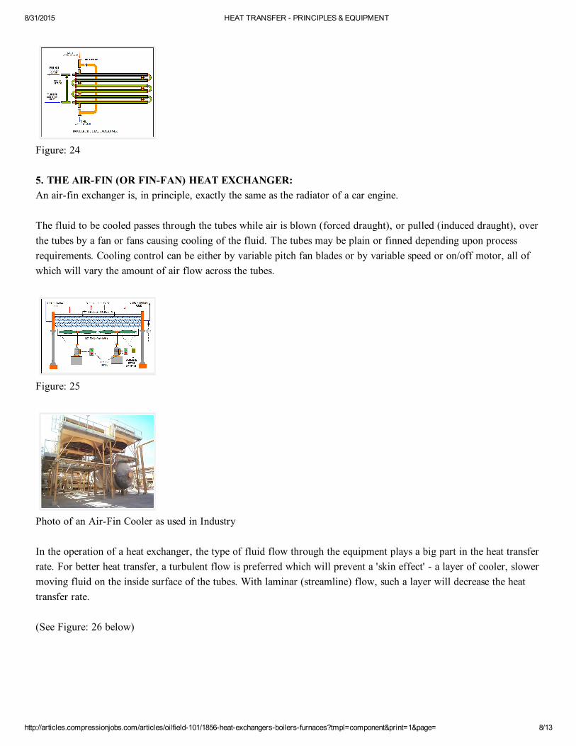
5. THE AIRFIN (OR FINFAN) HEAT EXCHANGER: An airfin exchanger is, in principle, exactly the same as the radiator of a car engine.
The fluid to be cooled passes through the tubes while air is blown (forced draught), or pulled (induced draught), overthe tubes by a fan or fans causing cooling of the fluid. The tubes may be plain or finned depending upon processrequirements. Cooling control can be either by variable pitch fan blades or by variable speed or on/off motor, all ofwhich will vary the amount of air flow across the tubes.
Figure: 25
Photo of an AirFin Cooler as used in Industry
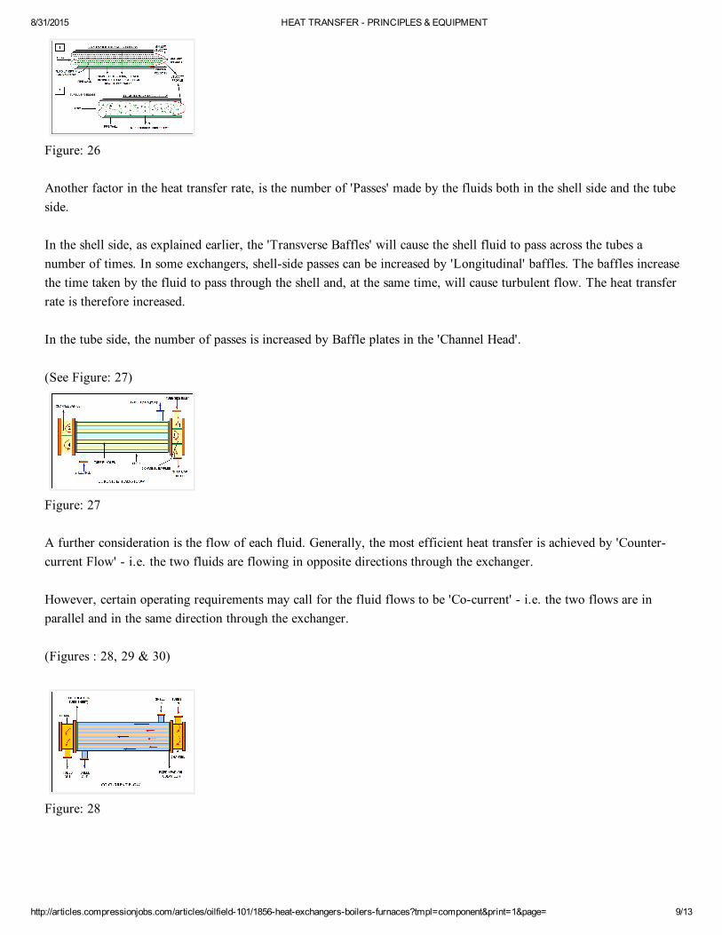
In the operation of a heat exchanger, the type of fluid flow through the equipment plays a big part in the heat transferrate. For better heat transfer, a turbulent flow is preferred which will prevent a 'skin effect' a layer of cooler, slowermoving fluid on the inside surface of the tubes. With laminar (streamline) flow, such a layer will decrease the heattransfer rate.
(See Figure: 26 below)
8/31/2015 HEAT TRANSFER PRINCIPLES & EQUIPMENT
http://articles.compressionjobs.com/articles/oilfield101/1856heatexchangersboilersfurnaces?tmpl=component&print=1&page= 9/13
Figure: 26
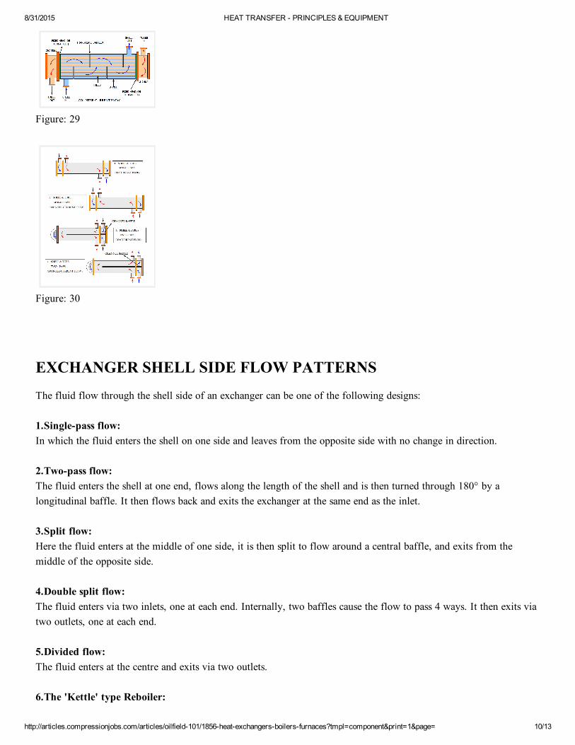
Another factor in the heat transfer rate, is the number of 'Passes' made by the fluids both in the shell side and the tubeside.
In the shell side, as explained earlier, the 'Transverse Baffles' will cause the shell fluid to pass across the tubes anumber of times. In some exchangers, shellside passes can be increased by 'Longitudinal' baffles. The baffles increasethe time taken by the fluid to pass through the shell and, at the same time, will cause turbulent flow. The heat transferrate is therefore increased.
In the tube side, the number of passes is increased by Baffle plates in the 'Channel Head'.
(See Figure: 27)
Figure: 27
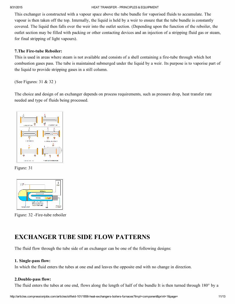
A further consideration is the flow of each fluid. Generally, the most efficient heat transfer is achieved by 'Countercurrent Flow' i.e. the two fluids are flowing in opposite directions through the exchanger.
However, certain operating requirements may call for the fluid flows to be 'Cocurrent' i.e. the two flows are inparallel and in the same direction through the exchanger.
(Figures : 28, 29 & 30)
Figure: 28
8/31/2015 HEAT TRANSFER PRINCIPLES & EQUIPMENT
http://articles.compressionjobs.com/articles/oilfield101/1856heatexchangersboilersfurnaces?tmpl=component&print=1&page= 10/13
Figure: 29
Figure: 30
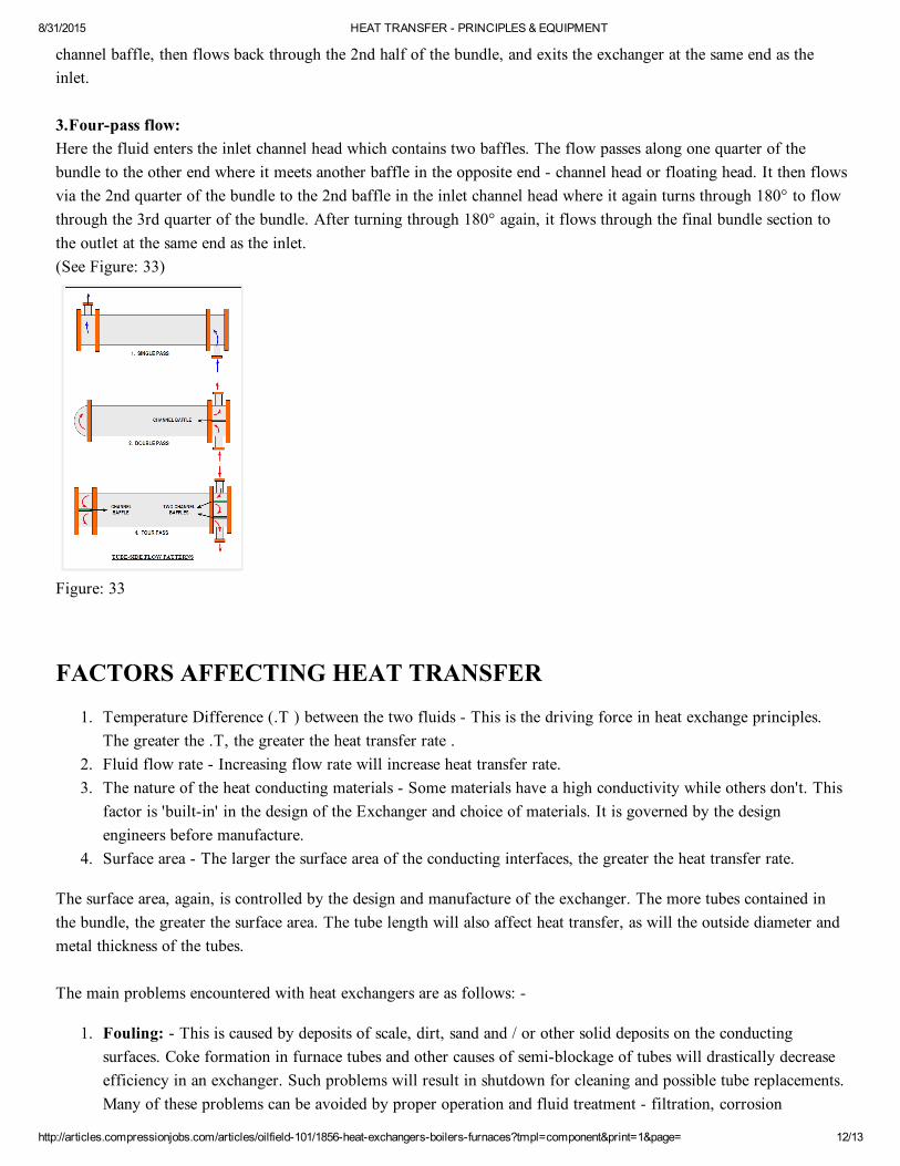
EXCHANGER SHELL SIDE FLOW PATTERNS
The fluid flow through the shell side of an exchanger can be one of the following designs:
1.Singlepass flow:In which the fluid enters the shell on one side and leaves from the opposite side with no change in direction.
2.Twopass flow: The fluid enters the shell at one end, flows along the length of the shell and is then turned through 180° by alongitudinal baffle. It then flows back and exits the exchanger at the same end as the inlet.
3.Split flow:Here the fluid enters at the middle of one side, it is then split to flow around a central baffle, and exits from themiddle of the opposite side.
4.Double split flow: The fluid enters via two inlets, one at each end. Internally, two baffles cause the flow to pass 4 ways. It then exits viatwo outlets, one at each end.
5.Divided flow: The fluid enters at the centre and exits via two outlets.
6.The 'Kettle' type Reboiler:
8/31/2015 HEAT TRANSFER PRINCIPLES & EQUIPMENT
http://articles.compressionjobs.com/articles/oilfield101/1856heatexchangersboilersfurnaces?tmpl=component&print=1&page= 11/13
This exchanger is constructed with a vapour space above the tube bundle for vaporised fluids to accumulate. Thevapour is then taken off the top. Internally, the liquid is held by a weir to ensure that the tube bundle is constantlycovered. The liquid then falls over the weir into the outlet section. (Depending upon the function of the reboiler, theoutlet section may be filled with packing or other contacting devices and an injection of a stripping fluid gas or steam,for final stripping of light vapours).
7.The Firetube Reboiler:This is used in areas where steam is not available and consists of a shell containing a firetube through which hotcombustion gases pass. The tube is maintained submerged under the liquid by a weir. Its purpose is to vaporise part ofthe liquid to provide stripping gases in a still column.
(See Figures: 31 & 32 )
The choice and design of an exchanger depends on process requirements, such as pressure drop, heat transfer rateneeded and type of fluids being processed.
Figure: 31
Figure: 32 Firetube reboiler
EXCHANGER TUBE SIDE FLOW PATTERNS
The fluid flow through the tube side of an exchanger can be one of the following designs:
1. Singlepass flow: In which the fluid enters the tubes at one end and leaves the opposite end with no change in direction.
2.Doublepass flow:The fluid enters the tubes at one end, flows along the length of half of the bundle It is then turned through 180° by a
8/31/2015 HEAT TRANSFER PRINCIPLES & EQUIPMENT
http://articles.compressionjobs.com/articles/oilfield101/1856heatexchangersboilersfurnaces?tmpl=component&print=1&page= 12/13
channel baffle, then flows back through the 2nd half of the bundle, and exits the exchanger at the same end as theinlet.
3.Fourpass flow: Here the fluid enters the inlet channel head which contains two baffles. The flow passes along one quarter of thebundle to the other end where it meets another baffle in the opposite end channel head or floating head. It then flowsvia the 2nd quarter of the bundle to the 2nd baffle in the inlet channel head where it again turns through 180° to flowthrough the 3rd quarter of the bundle. After turning through 180° again, it flows through the final bundle section tothe outlet at the same end as the inlet. (See Figure: 33)
Figure: 33
FACTORS AFFECTING HEAT TRANSFER
1. Temperature Difference (.T ) between the two fluids This is the driving force in heat exchange principles.The greater the .T, the greater the heat transfer rate .
2. Fluid flow rate Increasing flow rate will increase heat transfer rate.3. The nature of the heat conducting materials Some materials have a high conductivity while others don't. This
factor is 'builtin' in the design of the Exchanger and choice of materials. It is governed by the designengineers before manufacture.
4. Surface area The larger the surface area of the conducting interfaces, the greater the heat transfer rate.
The surface area, again, is controlled by the design and manufacture of the exchanger. The more tubes contained inthe bundle, the greater the surface area. The tube length will also affect heat transfer, as will the outside diameter andmetal thickness of the tubes.
The main problems encountered with heat exchangers are as follows:
1. Fouling: This is caused by deposits of scale, dirt, sand and / or other solid deposits on the conductingsurfaces. Coke formation in furnace tubes and other causes of semiblockage of tubes will drastically decreaseefficiency in an exchanger. Such problems will result in shutdown for cleaning and possible tube replacements.Many of these problems can be avoided by proper operation and fluid treatment filtration, corrosion
8/31/2015 HEAT TRANSFER PRINCIPLES & EQUIPMENT
http://articles.compressionjobs.com/articles/oilfield101/1856heatexchangersboilersfurnaces?tmpl=component&print=1&page= 13/13
inhibition, furnace firing control .. etc.2. Air pockets: The formation of air pockets in exchanges due to improper venting at start up, or build of gas
from light materials, will affect the heat transfer rate. This can be avoided by venting all air or gas out at startup and periodically venting gases as required.
3. Leakage: Most leakages occur due to gasket failure replacement of gaskets will be necessary. Internalleakage due to tube failure will cause contamination of the lower pressure fluid by the ingress of higherpressure fluid. This will require tube 'plugging' or replacement. Tube failure generally occurs due to corrosion,excessive pressure or by failure of the welded or rolled fitting of the tubes into the tubesheets.
About the Author
Norrie is a retired professional who has been working in Oil and Gas and LNG production in MarsaelBrega, Libyafor 30 years.
Norrie used to be in the Training Dept. and prepared Programmes for Libyan Traine
Last Updated on Wednesday, 24 February 2010 19:40