Heat Pump Installation, Maintenance and Service...
19
5/5/2017 Heat Pump Installation, Maintenance and Service Manual This booklet is to be carefully read and instructions followed for efficient and trouble free operation of the Accent Swimming Pool Heat Pump 43 Marigold Street Revesby NSW 2212 Tel: (02) 9684 3684 Fax: (02) 9684 3698 ABN 28 062 383 224
Transcript of Heat Pump Installation, Maintenance and Service...
5/5/2017
Heat Pump Installation, Maintenance and Service Manual
This booklet is to be carefully read and instructions followed for efficient and trouble free operation of the
Accent Swimming Pool Heat Pump
43 Marigold Street Revesby NSW 2212
Tel: (02) 9684 3684 Fax: (02) 9684 3698
ABN 28 062 383 224

TABLE OF CONTENTS
INTRODUCTION ................................................................................................. 1
SECTION 1 INSTALLATION ............................................................................. 2
Site Location, Preparation & Unit Positioning ................................................................ 2 Plumbing ....................................................................................................................... 3 Chemical Treatment ...................................................................................................... 3 Electrical ....................................................................................................................... 4 Control Design for Pool Heating .................................................................................... 4 Link between Heat Pump, Water Pump and Thermostat for Pool Heating ..................... 4 Precautions ................................................................................................................... 5
SECTION 2 COMMISSIONING .......................................................................... 6
SECTION 3 OPERATION .................................................................................. 6
Thermostat Operation .................................................................................................. 7 Heat Up Time ............................................................................................................... 7 De-Icing ........................................................................................................................ 7 Pool Application ........................................................................................................... 7
SECTION 4 MAINTENANCE ............................................................................. 8
Heat Exchanger Care .................................................................................................... 8 Service Assistance ........................................................................................................ 9
SECTION 5 TROUBLESHOOTING .................................................................. 10
Machine Will Not Start .................................................................................................10 Pool Will Not Heat .......................................................................................................10 Compressor Will Not Run ............................................................................................10 Compressor Motor Hums But Will Not Start.................................................................10
SECTION 6 INSTALLATION SCHEMATIC DRAWINGS ................................... 11
Typical Single Pool Heat Pump Schematic For Pool Filtration ...................................11 Typical Single Pool Heating Schematic ......................................................................11 Typical Multiple Pool Heat Pump Installation .............................................................12 Typical Schematic for Single Hot Water Heat Pump ..................................................12
SECTION 7 WARRANTY ............................................................................... 113

INTRODUCTION
Accent Hot Water Heat Pumps are available in sizes from 8kW to 300kW nominal output. The units are most commonly manufactured as air-to-water design, in which it extracts heat from ambient air and transfer it into the water, to provide the most cost efficient method of water heating. The units can also be manufactured as water-to-water or ground-coupled design. Each is a fully packaged unit, requiring only electrical and water connections to be made on installation. Each is factory charged, with refrigerant R407 being ideally suited for commercial or industrial
situations requiring hot water up to 60°C or up to 40°C for pool heating. Accent also manufactures with R410A and R134A may be used for special hot water applications. The Accent heat pump is installed to a wide diversity of commercial and industrial applications. The performance of the unit varies with ambient operating conditions, water flow, and water temperature and as such, selection should be done in conjunction with an experienced heat pump dealer or the manufacturer. Each Accent unit is custom-manufactured to meet specific task/site requirements and a wide range of options is available in unit design. It is characteristic of heat pumps to form ice on the evaporator at cool ambients. As such, various de-ice mechanism options are provided. This manual includes important information in regard to installation, operation, maintenance and servicing and should be retained for the life of the heater. Correct installation and familiarity with the operational guidelines is important.

SECTION 1 INSTALLATION
For validity of the Accent Air warranty, installation must be carried out by registered trade person.
Delivery
• Reference should be made to the unit specifications to determine weight and lifting requirements.
• Packaging materials should be removed upon delivery so to avoid any sweating of the electrical compartment or potential staining to the case, particularly in tropical areas.
Site Location, Preparation & Unit Positioning
• Heat Pump heating efficiency and output increases with the rise in entering air temperature and as such, it is not necessary for the unit to be placed in sunlight in the manner of a solar heating system. On the other hand, direct sunlight to the evaporator may provide a marginal increase in heat transfer and would assist in the removal of ice formation in cold climate locations.
• Locating the Heat Pump close to other system equipment like filter, pump, tank, etc will minimise friction and heat losses.
• It is important that the Clearance Guidelines included in this Manual are read and understood. These guidelines set out the minimum clearance requirements in respect of air flow and servicing.
• Free circulation of air across the coil, requires no obstructions on the intake or fan discharge of Heat Pumps. In addition, care should be taken to ensure that walls, eaves, etc do not obstruct the release of discharge air such that this may recirculate in the incoming air stream of the unit.
• For the plant-room installation, make sure that sufficient fresh air is available via provision of inlet grills in building design, etc. Exhaust air from the Heat Pump must be discharged by a duct away from the fresh air supply. Never install in an enclosed area.
• Service access is required at both ends of the Heat Pump as per the Clearance Guidelines (See attached)
• Where multiple units are to be installed, minimum clearance requirements increase.
• The Heat Pump requires a firm base, say concrete slab. Rubber mounts should be installed between the unit and slab.
• Drainage of condensate and entering rain water will occur at drainage points provided at the plumbing end of the unit. To ensure proper drainage, make sure that the unit is located at a slightly tilted angle with the drain on the downhill side of the unit. This can be done by making the concrete slab slightly higher at one end or lifting one end of the unit by rubber mounts, noting that the larger units include inbuilt 50mm fall. If the unit is to be installed internally, it is recommended that it sit within a separate drip tray, with provision for drainage of this water to a drain, etc. Ideally, the condensate drain provision connected to the heat pump drip tray or to the drainage points in the heat pump should be flexible and able to be readily removed for cleaning. Clear plastic connections at the drain will allow the owner to check that debris/dust etc has not restricted the condensate drains. It is important that water is not allowed to pond within the unit so as to avoid corrosion to the base of the compressor or heat exchangers.
• Local building authorities should be consulted for regulations concerning minimum installation distance from pool or other amenities.
• Units to be used in areas having corrosive atmospheres should be specified at time of ordering.
• Consideration should be given to the operating noise, wherever possible the exhaust should be
directed away from the occupied areas.

Plumbing
• It is preferable that the heat pump is connected to filtered water.
• It is essential that the water recirculating pump and pipe sizes be engineered to suit the particular application, giving correct water flow through the heat pump as per the specification requirements of the unit. Inadequate or excessive water flow detracts from heating efficiency and can lead to damage to the unit. Selection of the recirculating pump must be made in accordance with the design flow rate and pressure as per the pump manufacturer’s specification.
• If unsure, contact Accent for recommendations on the optimum flow rate. Assistance will be provided where possible in relation to plumbing design and pump selection.
• Water connections on the unit are clearly marked as water inlet and water outlet.
• The installation of breakable unions on both inlet and outlet pipes will facilitate maintenance and water drainage of the system. If the unit is situated below the pool level or an open holding tank, shut off valves should be fitted on the water side of both unions so that removal of the machine is possible without draining the system.
• A separate circuit is generally the most desirable plumbing configuration with individual flow and return line and filter strainer. This may not always be possible particularly with established pools.
• Heat pumps may be plumbed in-line with existing filter equipment, although thought must be given to correct flow, run time and possible over chlorinating and/or dosing by extended running of automatic chlorinator, feeders, etc. Typical plumbing schematics for installation with existing filtration and with a dedicated heating circuit are shown in Section 6.
• A one-way check valve should be installed on the outlet of the heat pump.
• Models without an internal water flow by-pass must have an external by-pass fitted.
• Where multiple units are installed, the heaters must be installed in parallel to equalise pressure drops and balance flow through the heaters. Systems of two or more Heat Pumps require a manifold.
• All Plumbing should be carried out by qualified tradesman (plumber).
Chemical Treatment
Accent heat pumps designed for swimming pool or spa heating will include a titanium heat exchanger. This material is impervious to chemical corrosion and as such, variations in water quality will not cause damage to the titanium tube. However, it is recommended as a matter of good pool management that the correct chemical balance of the water be maintained as follows:
• pH to be kept between 7.2 and 7.8
• Alkalinity must not exceed 200 PPM
• Free available chlorine must not exceed 6.0 PPM
• Chemicals must be added down stream side of the Heat Pump.
• In line chlorinator must be installed down stream of the Heat Pump. The maintenance of the above guidelines does not in itself ensure that water is in balance and non-corrosive. Various mechanisms are available to monitor water conditions and information on the Langlier Saturation Index is provided as a commonly applied industry standard.
Electrical
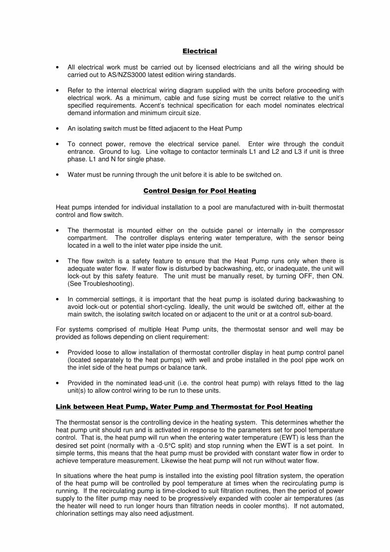
• All electrical work must be carried out by licensed electricians and all the wiring should be carried out to AS/NZS3000 latest edition wiring standards.
• Refer to the internal electrical wiring diagram supplied with the units before proceeding with electrical work. As a minimum, cable and fuse sizing must be correct relative to the unit’s specified requirements. Accent’s technical specification for each model nominates electrical demand information and minimum circuit size.
• An isolating switch must be fitted adjacent to the Heat Pump
• To connect power, remove the electrical service panel. Enter wire through the conduit entrance. Ground to lug. Line voltage to contactor terminals L1 and L2 and L3 if unit is three phase. L1 and N for single phase.
• Water must be running through the unit before it is able to be switched on.
Control Design for Pool Heating
Heat pumps intended for individual installation to a pool are manufactured with in-built thermostat control and flow switch.
• The thermostat is mounted either on the outside panel or internally in the compressor compartment. The controller displays entering water temperature, with the sensor being located in a well to the inlet water pipe inside the unit.
• The flow switch is a safety feature to ensure that the Heat Pump runs only when there is adequate water flow. If water flow is disturbed by backwashing, etc, or inadequate, the unit will lock-out by this safety feature. The unit must be manually reset, by turning OFF, then ON. (See Troubleshooting).
• In commercial settings, it is important that the heat pump is isolated during backwashing to avoid lock-out or potential short-cycling. Ideally, the unit would be switched off, either at the main switch, the isolating switch located on or adjacent to the unit or at a control sub-board.
For systems comprised of multiple Heat Pump units, the thermostat sensor and well may be provided as follows depending on client requirement:
• Provided loose to allow installation of thermostat controller display in heat pump control panel (located separately to the heat pumps) with well and probe installed in the pool pipe work on the inlet side of the heat pumps or balance tank.
• Provided in the nominated lead-unit (i.e. the control heat pump) with relays fitted to the lag unit(s) to allow control wiring to be run to these units.
Link between Heat Pump, Water Pump and Thermostat for Pool Heating
The thermostat sensor is the controlling device in the heating system. This determines whether the heat pump unit should run and is activated in response to the parameters set for pool temperature control. That is, the heat pump will run when the entering water temperature (EWT) is less than the
desired set point (normally with a -0.5°C split) and stop running when the EWT is a set point. In simple terms, this means that the heat pump must be provided with constant water flow in order to achieve temperature measurement. Likewise the heat pump will not run without water flow. In situations where the heat pump is installed into the existing pool filtration system, the operation of the heat pump will be controlled by pool temperature at times when the recirculating pump is running. If the recirculating pump is time-clocked to suit filtration routines, then the period of power supply to the filter pump may need to be progressively expanded with cooler air temperatures (as the heater will need to run longer hours than filtration needs in cooler months). If not automated, chlorination settings may also need adjustment.

By contrast, in warmer months the heat pump will run less hours than the filter. The heat pump may be left ON, (i.e. with power supply), as it will only run if the pool temperature falls below the
desired set point by -0.5°C. Where the Heat Pump is installed on a separate heating circuit (i.e. separate recirculating pump), the ideal scenario is that a control logic/interface is in place between the heat pump and the recirculating pump. That is, flow is provided only when heating is required so that the pump use is limited strictly to those hours needed to maintain the pool temperature. The Accent heat pump may be provided with pump-call or a pump control function so that a run signal is provided to the pump via the heat pump’s controller based on temperature signals. PRECAUTIONS Where damage to property can occur in the event of the heat pump leaking, the unit must be installed in a drained drip tray in accordance with AS/NZS3500.4 and local codes and regulatory authority requirements. The heat pump must be maintained in accordance with the Owners Guide and Installation Instructions. If the heat pump is to be used in a commercial application, you should ensure that you have adequate redundancy within the heating system. This should ensure the continuity of heating in the event that the heat pump should become inoperable for any reason. We recommend that you seek advice from your Accent Air representative or your specifier about your needs and building redundancy into your heating system. In operating your heat pump, you should ensure that the hydraulic layout of the system is correct. Particular care should be given to ensure that excess pressure is not created to the heat pump’s internal heat exchanger(s).
SECTION 2 COMMISSIONING
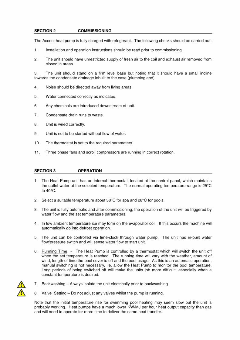
The Accent heat pump is fully charged with refrigerant. The following checks should be carried out: 1. Installation and operation instructions should be read prior to commissioning. 2. The unit should have unrestricted supply of fresh air to the coil and exhaust air removed from
closed in areas. 3. The unit should stand on a firm level base but noting that it should have a small incline towards the condensate drainage inbuilt to the case (plumbing end). 4. Noise should be directed away from living areas. 5. Water connected correctly as indicated. 6. Any chemicals are introduced downstream of unit. 7. Condensate drain runs to waste. 8. Unit is wired correctly. 9. Unit is not to be started without flow of water. 10. The thermostat is set to the required parameters. 11. Three phase fans and scroll compressors are running in correct rotation. SECTION 3 OPERATION
1. The Heat Pump unit has an internal thermostat, located at the control panel, which maintains
the outlet water at the selected temperature. The normal operating temperature range is 25°C
to 40°C.
2. Select a suitable temperature about 38°C for spa and 28°C for pools. 3. The unit is fully automatic and after commissioning, the operation of the unit will be triggered by
water flow and the set temperature parameters. 4. In low ambient temperature ice may form on the evaporator coil. If this occurs the machine will
automatically go into defrost operation. 5. The unit can be controlled via time-clock through water pump. The unit has in-built water
flow/pressure switch and will sense water flow to start unit. 6. Running Time ~ The Heat Pump is controlled by a thermostat which will switch the unit off
when the set temperature is reached. The running time will vary with the weather, amount of wind, length of time the pool cover is off and the pool usage. As this is an automatic operation, manual switching is not necessary, i.e. allow the Heat Pump to monitor the pool temperature. Long periods of being switched off will make the units job more difficult, especially when a constant temperature is desired.
7. Backwashing – Always isolate the unit electrically prior to backwashing.
8. Valve Setting – Do not adjust any valves whilst the pump is running. Note that the initial temperature rise for swimming pool heating may seem slow but the unit is probably working. Heat pumps have a much lower KW/MJ per hour heat output capacity than gas and will need to operate for more time to deliver the same heat transfer.

Thermostat Operation
The temperature shown in normal display mode is the entering water temperature (i.e. the current water temperature).
To check or adjust the current set-point temperature, reference should be made to the controller manufacturer’s operating instructions provided with the unit documentation.
As a guide heat pumps fitted with an Carel PJEZ control: To check set point, push and hold the “Set” button for 1 second, current set point will be displayed, push the “up” or “down” arrows to adjust the value. Press “set” to confirm the value.
Adjusting the differential or Hysteresis “All parameters” screen must be accessed. Press and hold “Set” for approx 5 seconds, PS will be displayed. Press “Set” then “Arrow up” till the password value “22” is displayed “PS” will be displayed Press “Arrow up” unit parameter “rd” is displayed. Press “Set” Value will be displayed. Press “Arrow up” or “Down” to set the desired value. Press “Set” Press and hold “Set” for approx 5 seconds, until temperature is displayed to save values.
Further instructions on the operation of the PJEZ controller and a detailed table of the operating parameters is provided in the back section of this manual.
As a guide, heat pumps fitted with the Rheem IQ® tariff intelligent control – Refer to the Rheem IQ Tariff Controller User Manual
• The relevant Carel PJEZ easy or Rheem IQ operating manuals should have been provided to you with delivery of the heater. If these have not been received, please contact us directly and we will be pleased to provide copies.
Heat Up Time
Heat up time on pool and spa will vary depending on outside air temperature, wind speed over pool, amount of sun on pool, unit size and running time available. To maintain temperature and reduce running cost a heat retention blanket must be used overnight or whenever pool or spa is not in use.
De-Icing
Pool Application Refrigerant hot gas by-pass is intended for locations where ice build-up on cooling coils will be occasionally experienced.
Reverse cycle de-icing system is intended where ambient temperatures are likely to fall below 5°C for prolonged periods.

SECTION 4 PERIODIC MAINTENANCE
It is recommended minor maintenance be performed monthly by the dwelling or pool owner. The minor maintenance includes: 1. Depending on the location of the unit, fins of the coil must be cleaned periodically. 2. Check condensate drain for blockages. 3. Ensure that water is not collecting in the base of the unit. RECOMMENDED ACCENT AIR SERVICE PROCEDURE
1. Depending on the location of the unit, fins of the coil must be cleaned periodically. 2. In locations where ambient temperature can be very low, if unit is not used for a long period, it
is essential to drain all water from unit to prevent ice build-up in water pipe-work. 3. Leak test refrigerant system once every 6 months. 4. Check correct function of pressure switches, de-ice control and solenoid valves if fitted. 5. Check thermostat. 6. Check fan motor support and fan blades for vibration or noise. 7. Check condensate drain for blockages. 8. Check water inlet and outlet connections for any leaks. 9. Check current draw. 10. Check operating voltage at compressor terminal mains with load and at start-up. 11. For commercial installations, a program of servicing every four months is recommended and
should be undertaken by a specialist refrigeration mechanic. For residential applications, an annual service program is recommended.
12. The unit casing is designed for outdoors installation and no specific maintenance should be
necessary. If the case is cleaned, ensure that power to the unit is switched off. 13. Clean evaporator coils. If coils are becoming clogged with leaves or debris, remove any
surrounding source of leaf or other litter.
Heat Exchanger Care
• Care should be taken of the heat exchanger by correct approach to the hydraulic layout of the installation and chemical treatment.
• It is fundamental that the nominated flow rate of the unit be maintained and pump selection should be made with knowledge of the target figure. Reference should be made the individual unit’s specification with current requirements shown below. As specification data may vary with product development and/or where units are custom-manufactured, flow rates should be confirmed for validity with Accent at the time of installation.
• The heat pump includes an internal by-pass. The factory setting allows for the by-pass to be partially open, allowing diversion of part of the total flow.
• If the hydraulic layout and recirculating pump capacity is seen to provide a flow well above the specified flow litres/sec or at excess pressure, then an external by-pass should be installed or alternatively, the pump flow should be moderated.

• For seasonal shut-downs, always allow water to pass through the heater, even if the heater is not being used. If the heater is isolated with chlorinated water or in its water piping, chlorine gases may corrode the heat exchanger. Accent’s warranty will be voided where chemical corrosion is clearly diagnosed as the cause of failure.
• For shutdowns in locations experiencing freezing conditions, the piping system and heater must be drained. The heater should be flushed with clean fresh water for several minutes to wash away all traces of chemicals, then drained. It is recommended that the entire system is purged using pressurised air to force remaining water from the system.
• If water enters the refrigeration system due to heat exchanger failure, contact supplier for advice.
Caution! Motorised diverter valves must never be installed so that they can move through a closed inlet position while the pump is operating and allow the system to pressurise. This situation will void the Accent Air warranty and may significantly damage the pool heater and other system equipment.
Flow Rate Requirements
Models HWP8BB- HWP60 2.8l/sec
Models HWP80,100 & 120 5.6l/sec
Models HWP150-180 8.4l/sec
Models HWP200-300 11.2l/sec
SERVICE ASSISTANCE
• Service must only be undertaken by properly authorised personnel You may contact Accent directly on �02 9684 3684 or your local Accent distributor to arrange for your service or recommend a qualified service organisation. It will be necessary for you state the model number and serial number of your heater. This information will be found on the heater data plate.
How long will the Pool & Spa Heater Last
Your Accent pool heater is supported by a manufacturer’s warranty. There are a number of factors that will affect the length of service. These include but are not limited to the water chemistry, flow rate, the water pressure, the service & maintenance program and the usage pattern.
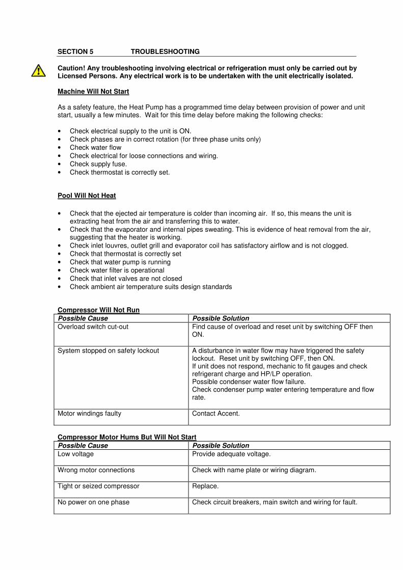
SECTION 5 TROUBLESHOOTING
Caution! Any troubleshooting involving electrical or refrigeration must only be carried out by Licensed Persons. Any electrical work is to be undertaken with the unit electrically isolated. Machine Will Not Start As a safety feature, the Heat Pump has a programmed time delay between provision of power and unit start, usually a few minutes. Wait for this time delay before making the following checks:
• Check electrical supply to the unit is ON.
• Check phases are in correct rotation (for three phase units only)
• Check water flow
• Check electrical for loose connections and wiring.
• Check supply fuse.
• Check thermostat is correctly set. Pool Will Not Heat
• Check that the ejected air temperature is colder than incoming air. If so, this means the unit is extracting heat from the air and transferring this to water.
• Check that the evaporator and internal pipes sweating. This is evidence of heat removal from the air, suggesting that the heater is working.
• Check inlet louvres, outlet grill and evaporator coil has satisfactory airflow and is not clogged.
• Check that thermostat is correctly set
• Check that water pump is running
• Check water filter is operational
• Check that inlet valves are not closed
• Check ambient air temperature suits design standards Compressor Will Not Run
Possible Cause Possible Solution
Overload switch cut-out Find cause of overload and reset unit by switching OFF then ON.
System stopped on safety lockout A disturbance in water flow may have triggered the safety lockout. Reset unit by switching OFF, then ON. If unit does not respond, mechanic to fit gauges and check refrigerant charge and HP/LP operation. Possible condenser water flow failure. Check condenser pump water entering temperature and flow rate.
Motor windings faulty Contact Accent.
Compressor Motor Hums But Will Not Start
Possible Cause Possible Solution
Low voltage Provide adequate voltage.
Wrong motor connections Check with name plate or wiring diagram.
Tight or seized compressor Replace.
No power on one phase Check circuit breakers, main switch and wiring for fault.
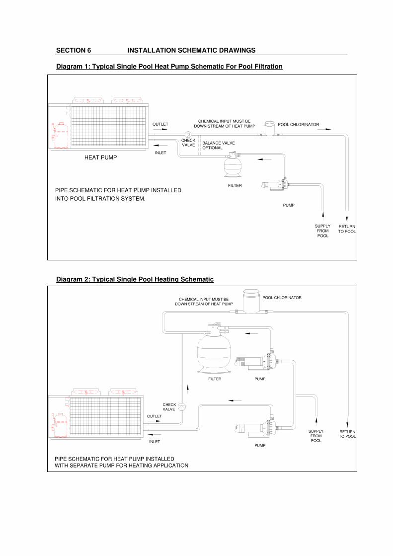
SECTION 6 INSTALLATION SCHEMATIC DRAWINGS
Diagram 1: Typical Single Pool Heat Pump Schematic For Pool Filtration
Diagram 2: Typical Single Pool Heating Schematic
BALANCE VALVE
OPTIONAL
FILTER
PUMP
OUTLET
INLET
CHEMICAL INPUT MUST BE
DOWN STREAM OF HEAT PUMP
RETURN
TO POOL
PIPE SCHEMATIC FOR HEAT PUMP INSTALLED
POOL CHLORINATOR
SUPPLY
FROM
POOL
INTO POOL FILTRATION SYSTEM.
HEAT PUMP
CHECKVALVE
FILTER PUMP
CHEMICAL INPUT MUST BE
DOWN STREAM OF HEAT PUMP
RETURN
TO POOL
PIPE SCHEMATIC FOR HEAT PUMP INSTALLED
WITH SEPARATE PUMP FOR HEATING APPLICATION.
POOL CHLORINATOR
OUTLET
INLETPUMP
SUPPLY
FROM
POOL
CHECK
VALVE

Diagram 3: Typical Multiple Pool Heat Pump Installation
Diagram 4: Typical Schematic for Single Hot Water Heat Pump
DWG NO:SCHEM-1TEL: (02) 9755-2855, FAX: (02) 9755-5098
UNIT 9, 16 BARRY ROAD; CHIPPING NORTON NSW 2170
ACCENT ON QUALITY AIR CONDITIONING EQUIPMENT
Accent Air PTY LTD
x 80mmx 100mm
x 100-80mm
x 100mm
x 100mm
x 100mm
x 100mm
x 100mm
16
6
1
6
4
12
36mELBOW
BUTTERFLY
CHECK VALVE
REDUCING BRUSH
STEEL FLANGE
BUTTERFLY VALVE
TEE
PIPE, CLASS 9x6
PRIMER GLUE
PIPE, CLASS 9
FLANGES PVC
ELBOW18 x 80mm
x 100mm
x 80mm
x 100mm
10
12
6
2L
FLANGES
HANGER
x 80mm24m
100mmØ
POOL
FROM
TO POOL
RETURN
VALVE
BUTTERFLY
100mmØ
FLANGES
VALVE
BUTTERFLY
INLINE PUMP
VALVE
CHECK
FILTRATION
PUMP
100mmØ
PVC FLANGE
STEEL FLANGE
TANK
250Ø
HEAT PUMP
HEAT PUMP
BUTTERFLY
BUTTERFLY
BUTTERFLY
BUTTERFLY
80mmØ
80mmØ
100mmØ
80mmØ
80mmØ
100mmØ
OUTLET
INLETVALVE
VALVE
OUTLET
INLETVALVE
VALVE
HEAT PUMP
BUTTERFLY
BUTTERFLY
80mmØ
OUTLET
INLETVALVE
VALVE
PIPE SCHEMATIC FOR HOT WATER HEAT PUMP
OUTLET
INLET
PUMP
CHECK
VALVE
MAIN'S
WATER IN
Y-STRAINER
GATE
VALVE
GATE
VALVE
GATE
VALVE
RETURN TO TANK
STORAGE
TANK
HOT
WATER
OUT
T'STAT
WELL

PJEZ easy Series
+AU00PJEZR rev1.3 - 02/12/2008
For technical support contact CAREL Australia Pty LtdSydney office ph: 02 8762 9200 fax: 02 9764 6933
Technical literature can be downloaded from www.carel.com
Please note: Please read these instruction in conjunction with the parameter list. It is recommended that the controllers be programmed before connecting or activating the plant to be controlled (eg. compressors)
** If the controller is keypad locked the value will not change. See parameter H2.

Code Parameter Unit Type Min.Max. Def. New Code Unit Type Min.Max. Def. New/2 Probe measurement stability - C 1 15 4 AE °C/°F C 0.1 20 5/4 Select display probe - F 1 3 1 Acd min C 0 250 0/5 Select °C or °F (0 = °C ) - C 0 1 0/6 Decimal point (0 = enabled, 1 = disabled) - C 0 1 0 F0 flag C 0 1 0
/C1 Calibration of probe 1 °C/°F F -127 127 0 F1 °C/°F F -50 127 5/C2 Calibration of probe 2 °C/°F F -127 127 0 F2 flag C 0 1 1/C3 Calibration of probe 3 °C/°F F -127 127 0 F3 flag C 0 1 1
Fd min F 0 15 1St Temperature set point °C/°F S r1 r2 4rd Controller differential °C/°F F 0 19 2 H0 - C 0 207 1r1 Minimum Set Point allowed °C/°F C -50 r2 -50 H1 flag C 0 3 0r2 Maximum Set Point allowed °C/°F C r1 150 90 H2 flag C 0 1 1r3 Mode 0=cool with defrost,1=cool only, 2=heating flag C 0 2 0 H4 flag C 0 1 0r4 Value to increase Set Point by from Digital Input °C/°F C 0 20 3 H5 flag F 0 31 -
EZY - C 0 4 0c0 Comp. and fan start delay at power up min C 0 100 0c1 Minimum time between 2 comp starts min C 0 100 0c2 Minimum compressor OFF time min C 0 100 0c3 Minimum compressor ON time min C 0 100 0c4 Duty setting min C 0 100 0cc Duration of continuous cycle hours C 0 15 4c6 Alarm bypass after continuous cycle hours C 0 15 2
d0 Defrost type (0=elec / temp,1= H.Gas / temp - C 0 4 02 = elec / time, 3 = hot gas / time … )
dI Interval between defrosts (if not using real time) hours F 0 199 8dt End defrost temperature, (if d0 = 0 or 1) °C/°F F -50 127 4dP Maximum defrost duration min F 1 199 30d4 Defrost at power up (0 = no, 1 = yes) - C 0 1 0d5 Defrost delay at power up (if d4=1) min C 0 199 0d6 Display during def.(0=dF (flash),1=locked) - C 0 1 1dd Dripping time after defrost min F 0 15 2 Buzzer & alarm relay LEDd8 Bypass alarms after defrost hours F 0 15 1 active ONd8d Alarm delayafter door open - from dig input hours C 0 250 0 not active ONd9 Defrost priority over compressor protection - C 0 1 0 not active ONd/ Display defrost probe temp d/1=def P1,d/2=def P2) °C/°F F - - - active ONdC Time basis for defrost (0=hr/min, 1=min/sec) - C 0 1 0 active ON
active ONA0 Alarm and fan differential °C/°F C -20 20 2 active ONAL Low alarm temp (if A0=<0 absolute, if A0>0 relative) °C/°F F -50 150 0 not active ONAH High alarm temp (if A0=<0 absolute, if A0>0 relative) °C/°F F -50 150 0 not active ONAd Low and high temperature alarm delay min C 0 199 0 not active ONA4 Configuration of digital input 1 - C 0 11 0 not active OFFA7 External alarm delay if using digital input min C 0 199 0 not active ONA8 Enable alarm ‘Ed' (defrost end on time) flag C 0 1 0 active ONAc High condenser temperature alarm set point °C/°F C -50 150 70 not active ON
[AL] [Ad][A4 = 7/8] [+A7][A4 = 1] [+A7]
EZY = 1: low temperature with hot gas defrost
E0
PJEZ (S, X)EZY = 2: normal temperature with timed defrostEZY = 3: normal temperature, heating outputEZY = 4: normal temperature, defrost controlled by temperature (d0 = 4)
if bands active[A4 = 10][A4 = 10][d6 = 0]
[dP] [dt] [d4] [A8]--
[AH] [Ad]
E1E2IA
ALARM TABLE
Alarm code Description
PJEZ easy summary of operating parameters
EZY parameter
Evaporator fan control set pointEnable evaporator fan control
Parameter
EZY = 4: low temperature, defrost controlled by temperature (d0 = 4)EZY = 3: low temperature with management of alarm via digital inputEZY = 2: low temperature with automatic night-time set point variation via digital input
PJEZ (C, Y)
EtC
Parameters involved
[d0 = 0/1/4] [F0 = 1][A4 = 10]
dOR
probe 1 error (control)probe 2 error (defrost)probe 3 error (cond)external alarmopen door alarmlow temperature alarmhigh temperature alarmunit parameter error
EF
LOHIEE
defrost ended by timeoutdefrost runningdirty condenser pre-alarm
CHt
EddFcht
dirty condenser alarmclock alarm
High cond. temp. alarm differentialHigh cond. temp. alarm delay
Fans delay after drippingFans in defrost (0 = on, 1 = off)Fans cycle with comp (0=no, 1=yes)
operating parameter error
-
EZY = 1: normal temperature, no defrost
Serial addressAUX output configuration
Select set of default parametersID code (read-only)Buzzer (0=enabled, 1 = disabled)Keypad (0=disabled, 1 = enabled)

SECTION 7 ACCENT WARRANTY - HWP & HWWP SERIES
1. THE ACCENT AIR WARRANTY – GENERAL
1.1 This warranty is given by Accent Air Pty Limited ABN 28 062 383 224 of 43 Marigold Street, Revesby New South Wales.
1.2 For the purposes of this document, the Accent heat pump water heater is referred to as the “unit”.
1.3 Accent offer a trained and qualified national service network who will repair or replace components at the address of the heat pump subject to the terms of the Accent warranty. Accent Air Service, in addition can provide preventative maintenance and advice on the operation of the unit. The Accent Service contact number is 02 9684 3684 with service personnel available to take your call from 8am to 4pm Monday to Friday, (hours subject to change).
1.4 For details about this warranty, you can contact us on 9684 3684
1.5 The terms of this warranty are set out in Section 2 and apply to units manufactured after 1st January 2012.
1.6 If a subsequent version of this warranty is published, the terms of that warranty will apply to units manufactured after the date specified in the subsequent version.
1.7 The application of the Warranty is dependent on payment for the unit being made in accordance with the Company's Standard Terms and Conditions.
2. TERMS OF THE ACCENT WARRANTY AND EXCLUSIONS TO IT
2.1 The warranty period will commence from the end user’s date of purchase.
2.2 The decision of whether to repair or replace a faulty component is at Accent Air’s sole discretion.
2.3 If you require a call out and we find that the fault is not covered by the Accent warranty, you are responsible for our standard call out charge. If you wish to have the relevant component repaired or replaced by Accent Air that service will be at your cost
2.4 Where a failed component is replaced under this warranty, the balance of the original warranty period will remain effective. The replacement does not carry a new Accent Air warranty.
2.5 Where the unit is installed outside the boundaries of a metropolitan area as defined by Accent or further than 25 km from either a regional Accent Air branch office or an Accredited Accent Service Agent's office, the cost of transport, insurance and travelling between the nearest branch office or Accent Air Accredited Service Agent’s office and the installed site shall be the owner’s responsibility.
2.6 Where the unit is installed in a position that does not allow safe or ready access, the cost of that access, including the cost of additional materials handling and/or safety equipment, shall be the owner’s responsibility. In other words, the cost of dismantling or removing cupboards, doors or walls and the cost of any special equipment to bring the pool heater to floor or ground level or to a serviceable position is not covered by this warranty.
2.7 This warranty only applies to the original and genuine Accent unit in its original installed location and any genuine Accent replacement parts.
2.8 The Accent warranty does not cover faults that are a result of:
a) Accidental damage to the unit or any component (for example: (i) Acts of God such as floods, storms, fires, lightning strikes and the like; and (ii) third party acts or omissions).
b) Misuse or abnormal use of the unit.
c) Installation not in accordance with the Owner’s Guide and Installation Instructions or with relevant statutory and local requirements in the State or Territory in which the unit is installed.
d) Connection at any time of the unit in anyway which does not comply with the guidelines as outlined in the Owner’s Guide and Installation Instructions.
e) Repairs, attempts to repair or modifications to the unit by a person other than Accent Service or an Accent Accredited Service Agent.
f) Faulty plumbing or faulty power supply.
g) Failure to maintain the unit in accordance with the Owner's Guide and Installation Instructions.
h) Transport damage where freight is arranged by others.
i) Fair wear and tear from adverse conditions (for example, corrosion).
j) Cosmetic defects.
2.9 Subject to any statutory provisions to the contrary, this warranty excludes any and all claims for damage to furniture, carpet, walls, foundations or any other consequential loss either directly or indirectly due to leakage from the unit, or due to leakage from fittings and/ or pipe work of metal, plastic or other materials caused by water temperature, workmanship or other modes of failure.
2.10 This warranty is not applicable if the installation of the unit is carried out by an installer not approved by Accent or persons who are not qualified to do so in the opinion of Accent Air.
2.11 Unless a titanium heat exchanger is fitted, this warranty does not cover repair or replacement of the Heat Exchanger due to corrosion caused by use of poor quality water not complying with the following

a) pH to be maintained between 7.0 and 8.0 b) alkalinity not exceeding 200ppm
2.12 Where a titanium heat exchanger is fitted, the extended warranty protects against failure due to water imbalance. The warranty is not applicable if failure is caused due to hydraulic damage, such as excess pressure. The extended parts warranty covers the cost of a replacement heat exchanger but excludes labour or associated costs or the cost of any subsequent damage, of any type.
2.13 This warranty does not cover the replacement or replenish of refrigerant within the unit.
2.14 It is a condition of warranty that the customer has stipulated correctly and precisely the capacity and performance required of the System and the conditions under which the System shall operate. Any performance figures given by us in the Quotation or mentioned or referred to in or prior to the contract are such as we expect to obtain on test but are not guaranteed. All such performance figures whether analytical or financial are estimates only and the customer must independently satisfy itself as to their accuracy and completeness.
Failure to perform as duly specified shall be notified to us in writing and we shall be given every reasonable facility to investigate the cause of the failure and to recommend remedial action.
If it is clearly established that the fault is due to an error in calculation by us or failure by our employees to carry out instructions, the fault shall be rectified by us in as reasonable a period of time as possible and at no cost to the Customer. Should the remedial action fail to achieve the designed performance the limit of our liability either the negligence or for breach of statutory duty or otherwise shall be for us to remove the equipment at our expense or to refund to the buyer the purchase price in full.
3. WHAT IS COVERED BY THE ACCENT WARRANTY FOR THE UNITS DETAILED IN THIS DOCUMENT
3.1 Accent will repair or replace a faulty component of your unit if it fails to operate in accordance with its specifications as follows:
Series What components are
covered
The period in which the fault must appear in order to be
covered What coverage you receive
HW, HWP, HWW & HWWP
Major Parts*
Years 1 to 2
1st Year repair and/or replacement of the faulty parts, free of charge, when installed for the purpose of heating a pool or spa.
2nd Year parts only.
Minor Parts* Year 1 Repair and/or replacement of the faulty
parts, free of charge, when installed for the purpose of heating a pool or spa
Protection of the heat exchanger due to chemical
corrosion Years 1 to 10
Repair and/or replacement of the faulty parts, free of charge, when installed for the
purpose of heating a pool or spa
All above models Labour Year 1 Repair and/or replacement of the faulty
parts, free of charge
• For the purposes of this warranty, Major Parts are defined as compressors, heat exchangers and evaporators. Minor Parts are defined as the remainder of the unit including refrigeration piping, valves, fans, electrical components and refrigerant.

4. ENTITLEMENT TO MAKE A CLAIM UNDER THIS WARRANTY
4.1 To be entitled to make a claim under this warranty you need to:
a) Be the owner of the unit or have consent of the owner to act on their behalf
b) Contact Accent Service without undue delay after detection of the defect and, in any event, within the applicable warranty period.
4.2 You are not entitled to make a claim under this warranty if your unit:
a) Does not have its original serial numbers or rating labels.
b) Is not installed in Australia.
5. HOW TO MAKE A CLAIM UNDER THIS WARRANTY
5.1 If you wish to make a claim under this warranty, you need to:
a) Contact Accent on 02 9684 3684 and provide owner’s details, address of the unit, a contact number and date of installation of the heater or if that’s unavailable, the date of manufacture, model and serial number (from the rating label on the heater)
b) Accent will arrange for the heater to be tested and assessed on-site.
c) If Accent determines that you have a valid warranty claim, Accent will repair or replace the heater in accordance with this warranty
5.2 Any expenses incurred in the making of a claim under this warranty will be borne by you.
6. THE AUSTRALIAN CONSUMER LAW
6.1 Our goods come with guarantees that cannot be excluded under the Australian Consumer Law. You are entitled to a replacement or refund for a major failure and for compensation for any other reasonably foreseeable loss or damage. You are also entitled to have the goods repaired or replaced if the goods fail to be of acceptable quality and the failure does not amount to a major failure.
6.2 The Accent warranty (set out above) is in addition to any rights and remedies that you may have under the Australian Consumer Law.
7. INTERNATIONAL WARRANTY PROVISIONS
7.1 Contact Accent for international warranty terms and conditions.