
Heat Exchangers with Cross Flow past Cylinders P M V Subbarao Professor Mechanical Engineering...
27
Heat Exchangers with Cross Flow past Cylinders P M V Subbarao Professor Mechanical Engineering Department I I T Delhi Another Common Industrial Application!!!
-
Upload
logan-owen -
Category
Documents
-
view
213 -
download
0
Transcript of Heat Exchangers with Cross Flow past Cylinders P M V Subbarao Professor Mechanical Engineering...

Heat Exchangers with Cross Flow past Cylinders
P M V SubbaraoProfessor
Mechanical Engineering Department
I I T Delhi
Another Common Industrial Application!!!
Convection heat transfer with banks of tubes
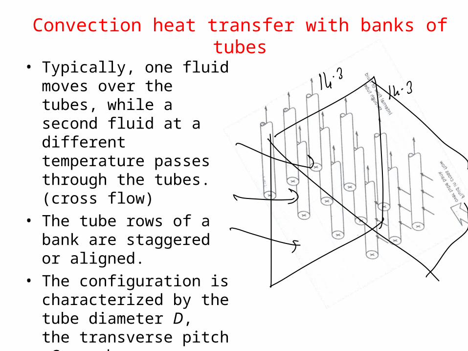
• Typically, one fluid moves over the tubes, while a second fluid at a different temperature passes through the tubes. (cross flow)
• The tube rows of a bank are staggered or aligned.
• The configuration is characterized by the tube diameter D, the transverse pitch ST and longitudinal pitch SL.

Inline Tube Bundle Staggered Tube Bundle
Characteristic Dimension of External Flow

•For Reynolds number
DV
Dmax
max,Re
VDS
SV
T
T
max V
DS
SV
D
T
)(2max
If staggered and 2
DSS T
D
or

•For tube bundles composed of 10 or more rows
3/11 PrRe13.1 max,
mD DCNu
10
0.7r
104Re2000
:for valid
4max,
L
D
N
P

Tube-Side Nusselt Number
For turbulent flow, the following equation developed by Petukhov-Kirillov is used:
2
322
1
28.3Reln58.1
1Pr2
7.1207.1
PrRe2
t
t
tt
tube
fWhere
f
f
Nu
Properties are evaluated at mean bulk temperature and constants are adjusted to fit experimental data.Validity range: 104 < Ret < 5 x 10⁶ and 0.5 < Prt < 2000 with 10% error.

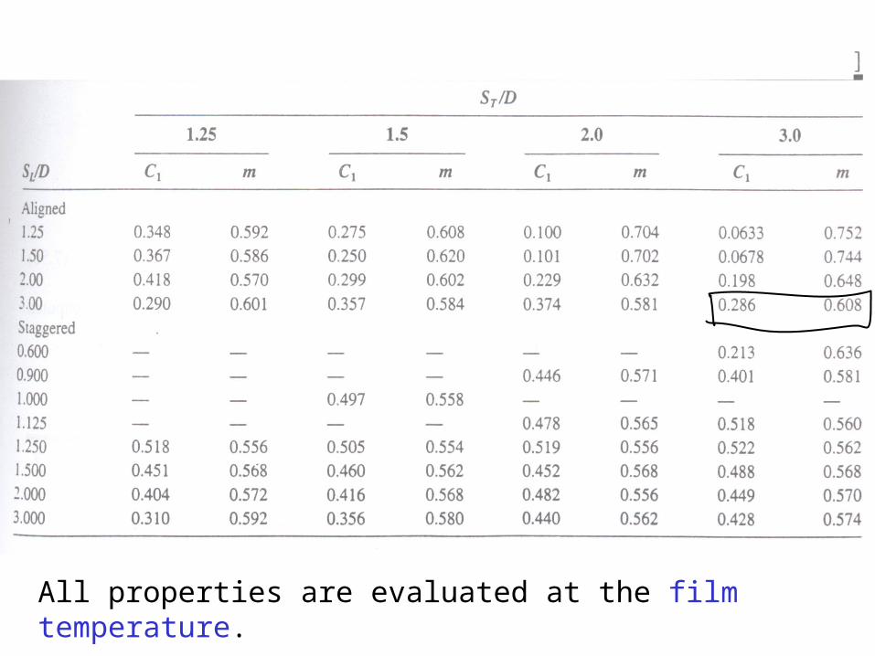
All properties are evaluated at the film temperature.

If number of tubes are less than 10, a correction factor is applied as:
)10(2
)10(
LL ND
ND NuCNu
And values for C2 are from table
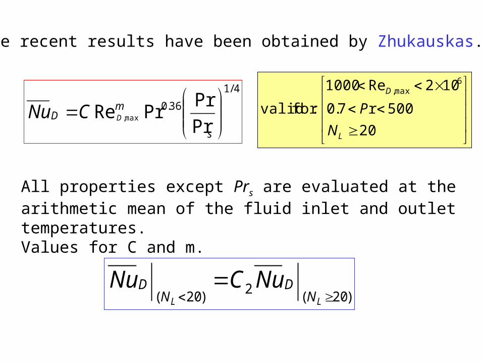
•More recent results have been obtained by Zhukauskas.
4/1
36.0
Pr
PrPrRe max,
s
mD DCNu
20
500r7.0
102Re1000
:for valid
6max,
L
D
N
P
All properties except Prs are evaluated at the arithmetic mean of the fluid inlet and outlet temperatures.Values for C and m.
)20(2
)20(
LL ND
ND NuCNu

t ρ cp μ *106 ν *106 K
[O C] [kg/m3] [kJ/kgK] [Pas] [m2/s] W/m.K
0 1.295 1.042 15.8 12.2 0.026
100 0.95 1.068 20.4 21.54 0.032
200 0.748 1.097 24.5 32.8 0.038
300 0.617 1.122 28.2 45.81 0.0448
400 0.525 1.151 31.7 60.38 0.0506
500 0.457 1.185 34.8 76.3 0.0565
600 0.405 1.214 37.9 93.61 0.0623
700 0.363 1.239 40.7 112.1 0.0678
800 0.33 1.264 43.4 131.8 0.0732
900 0.301 1.29 45.9 152.5 0.0782
1000 0.275 1.306 48.4 174.3 0.0837
1100 0.257 1.323 50.7 197.1 0.0891
1200 0.24 1.34 53 221 0.0946
Thermo-physical Properties of Combustion Products

Power Plant Heat Exchangers

Paths of Steam and Gas
Water walls
Drum
Economizer

Convective Superheater (Pendant)
• Convective super heaters are vertical type (Pendant ) or horizontal types.
• The Pendant SH is always arranged in the horizontal crossover duct.
• Pendant SH tubes are widely spaced due to high temperature and ash is soft.
• Transverse pitch : S1/d > 4.5
• Longitudinal pitch : S2/d > 3.5.
• The outside tube diameter : 32 – 51mm
• Tube thickness : 3 – 7mm
S1
S2
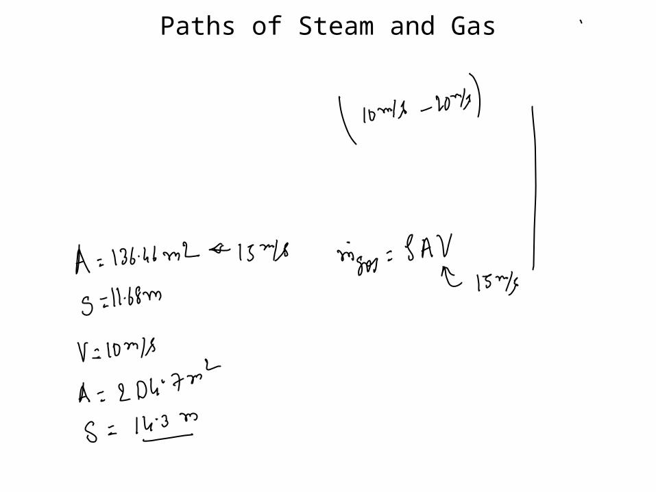
Paths of Steam and Gas

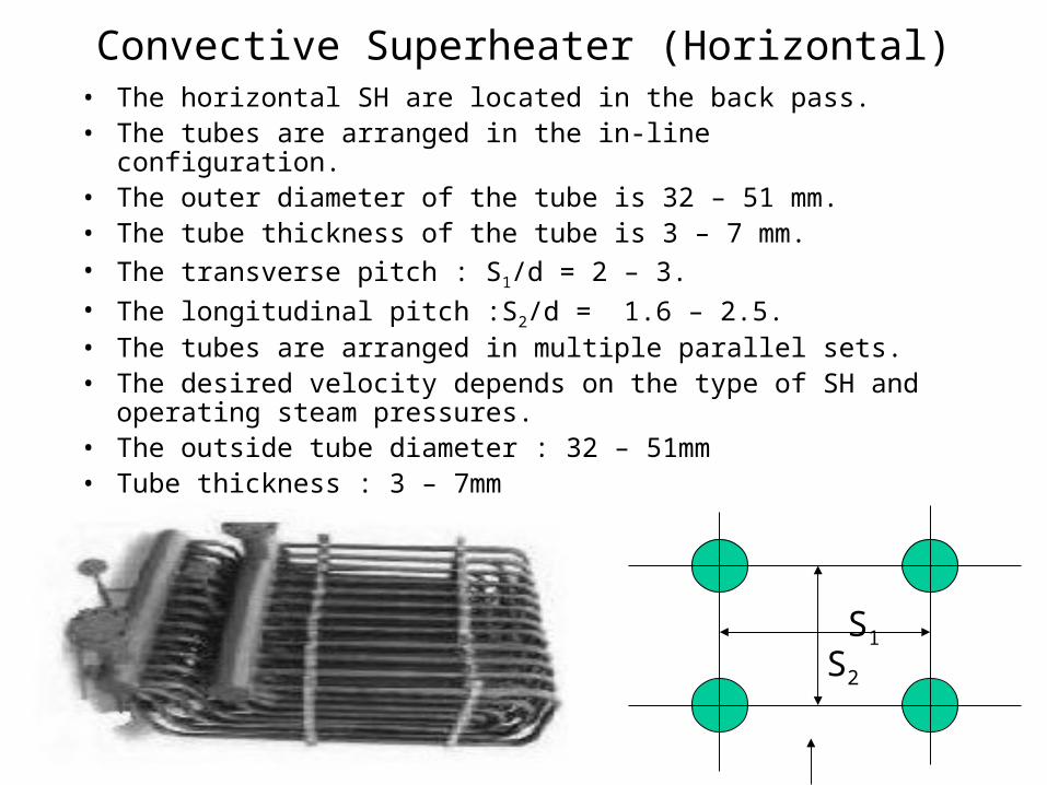
Convective Superheater (Horizontal)• The horizontal SH are located in the back pass.• The tubes are arranged in the in-line configuration.• The outer diameter of the tube is 32 – 51 mm.• The tube thickness of the tube is 3 – 7 mm.• The transverse pitch : S1/d = 2 – 3.• The longitudinal pitch :S2/d = 1.6 – 2.5.• The tubes are arranged in multiple parallel sets.• The desired velocity depends on the type of SH and operating steam
pressures.• The outside tube diameter : 32 – 51mm• Tube thickness : 3 – 7mm
S1
S2
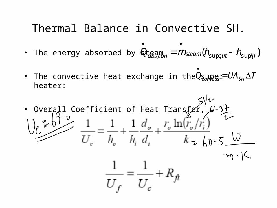
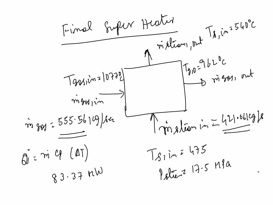
Thermal Balance in Convective SH.
• The energy absorbed by steam
• The convective heat exchange in the super heater:
• Overall Coefficient of Heat Transfer, U
)( sup,sup,, inoutsteamconabs hhmQ
TUAQ SHlosscon
,
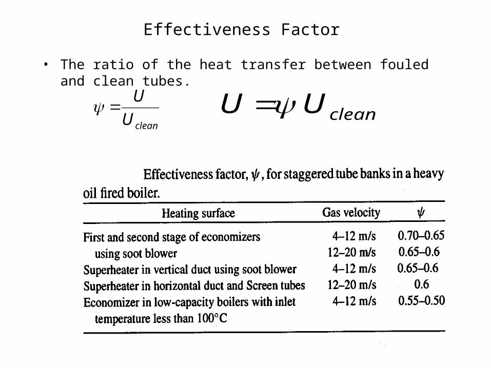
Effectiveness Factor
• The ratio of the heat transfer between fouled and clean tubes.
cleanU
U cleanUU

Thermal Balance in Super Heater.
• The energy absorbed by steam
• The convective heat lost by flue gas
• Overall Coefficient of Heat Transfer, U
)( sup,sup,, inoutsteamconabs hhmQ
TUAQ SHlosscon
,
Platen SH, U (W/m2 K) 120 – 140
Final SH, U (W/m2 K) 120 – 140
LTSH, U (W/m2 K) 60 – 80


Gas Temperatures
• Platen Super Heater:• Inlet Temperature: 1236.4 0C• Outlet Temperature: 1077 0C• Final Super Heater:• Inlet Temperature: 1077 0C• Outlet Temperature: 962.4 0C• Reheater:• Inlet Temperature: 962.4 0C• Outlet Temperature: 724.3 0C• Low Temperature Super
Heater:• Inlet Temperature: 724.30C• Outlet Temperature: 481.3 0C• Economizer:• Inlet Temperature: 481.3 0C• Outlet Temperature: 328.5 0C
Steam Temperatures
• Platen Super Heater:• Inlet Temperature: 404 0C• Outlet Temperature: 475 0C• Final Super Heater:• Inlet Temperature: 475 0C• Outlet Temperature: 540 0C• Reheater:• Inlet Temperature: 345 0C• Outlet Temperature: 5400C• Low Temperature Super
Heater:• Inlet Temperature: 3590C• Outlet Temperature: 404 0C• Economizer:• Inlet Temperature: 254 0C• Outlet Temperature: 302 0C

Real Mean Temperature Differences
• Three dimensionless parameters are introduced and used to compute real mean temperature difference.
incoldinhot
incoldouthot
TT
TT
,,
,,
cold
hot
C
C
hotC
UA
pc ZZ 1
324.01136.05.0 Z

1
1ep
1
1
ec