Heat Exchangers - Flo Fab · · 2017-11-08All plate hanging surtaces are stainless steel so...
52
SINCE 198 1 www.flofab.com 001-cat-2016-he Heat Exchangers Plate and Frame Shell and Tube Brazed FFW AHRI W & S FFB
-
Upload
truongtruc -
Category
Documents
-
view
224 -
download
2
Transcript of Heat Exchangers - Flo Fab · · 2017-11-08All plate hanging surtaces are stainless steel so...
SINCE 1981
www.flofab.com001-cat-2016-he
Heat ExchangersPlate and Frame
Shell and Tube
Brazed
FFW AHRI
W & S
FFB
TABLE OF CONTENTS
HISTORY
PLATE AND FRAME - PRODuCT SPECIFICATIONS.......................................................................2PLATE AND FRAME - TYPICAL SPECIFICATIONS.........................................................................3PLATE AND FRAME - GRID, CONNECTION TYPES, DESIGN LIMITS......................................4PLATE AND FRAME - SAVINGS EXPLANATIONS..........................................................................5SHELL AND TuBES - PRODuCT SPECIFICATIONS.......................................................................6SHELL AND TuBES - TYPICAL SPECIFICATIONS/ NOMENCLATuRE..................................7SHELL AND TuBES - GRID FOR ‘‘S’’ MODELS...........................................................................8-12SHELL AND TuBES - GRID FOR ‘‘SE’’ MODELS.......................................................................13-17SHELL AND TuBES - GRID FOR ‘‘W’’ MODELS.......................................................................18-22SHELL AND TuBES - GRID FOR ‘‘WF’’ MODELS...................................................................23-27NEW GENERATION :SHELL AND TuBES - GRID FOR ‘‘S’’ MODELS.......................................................................28-30SHELL AND TuBES - GRID FOR ‘‘W’’ MODELS......................................................................31-33SHELL AND TuBES - TYPICAL ‘‘S’’ CONNECTIONS SIZE AND TYPES..............................34SHELL AND TuBES - TRANSFER SOLuTION................................................................................35SHELL AND TuBES - SAVINGS EXPLANATIONS........................................................................36BRAZED - BL SERIES - PRODuCT SPECIFICATIONS........................................................37-50
Flo Fab was established in 1981 by Denis Gauvreau who created and developed the products line and constantly being perfected by Marc Gauvreau, as well as by a team of professional engineers and designers. It’s a combination of existing designs from several renowned products and the innovative ideas of a new generation professionals.
Through the years, Flo Fab has acquired several companies and service entities including : AQUA-PROFAB (ASME Tanks manufac-turer), MÉNARD, LÉONARD ÉLECTRIQUE, PMA. , Furthermore Flo Fab purchased equipment, fabrication designs and patterns from IDEALCO, a manufacturer of shell and tube type heat exchangers.The after sales services, sales, engineering, R&D, production, quality control, accounting and administration departments of all the above companies share the same location.
In December 2014, Marc Gauvreau, son of the founder, acquired all shares of The company. Flo Fab and is constantly investing in new state of the art innovations new product like the XRI series and Prefab Skid for Hydronic Hearing 8 cooling system, pumping systems. This has allowed Flo Fab to retain competent and experienced staff of professionals with varied and specialized abilities that constantly work on improving our existing products and add new engineered solutions that exceeding customer’s expectations .Flo Fab has grown quite rapidly and now proudly offers of a wide range of products available directly from one manufacturer. This includes pumps & pump packages, tanks, heat exchangers & hydronic accessories. This allows each project stakeholders to enjoy economical savings, peace of mind, best value for their investment and optimized total cost of ownership.
SINCE 1981
2
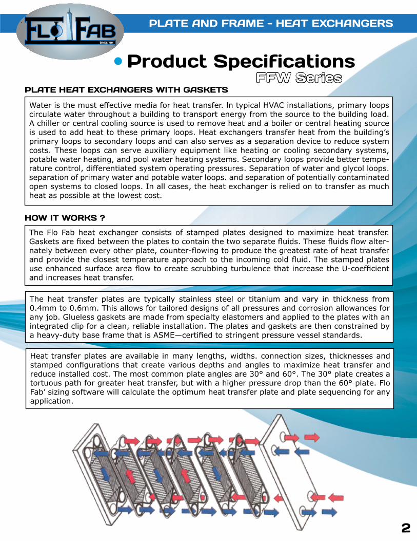
Water is the must effective media for heat transfer. ln typical HVAC installations, primary loops circulate water throughout a building to transport energy from the source to the building load. A chiller or central cooling source is used to remove heat and a boiler or central heating source is used to add heat to these primary loops. Heat exchangers transfer heat from the building’s primary loops to secondary loops and can also serves as a separation device to reduce system costs. These loops can serve auxiliary equipment like heating or cooling secondary systems, potable water heating, and pool water heating systems. Secondary loops provide better tempe-rature control, differentiated system operating pressures. Separation of water and glycol loops. separation of primary water and potable water loops. and separation of potentially contaminated open systems to closed loops. In all cases, the heat exchanger is relied on to transfer as much heat as possible at the lowest cost.
The Flo Fab heat exchanger consists of stamped plates designed to maximize heat transfer. Gaskets are fixed between the plates to contain the two separate fluids. These fluids flow alter-nately between every other plate, counter-flowing to produce the greatest rate of heat transfer and provide the closest temperature approach to the incoming cold fluid. The stamped plates use enhanced surface area flow to create scrubbing turbulence that increase the U-coefficient and increases heat transfer.
The heat transfer plates are typically stainless steel or titanium and vary in thickness from 0.4mm to 0.6mm. This allows for tailored designs of all pressures and corrosion allowances for any job. Glueless gaskets are made from specialty elastomers and applied to the plates with an integrated clip for a clean, reliable installation. The plates and gaskets are then constrained by a heavy-duty base frame that is ASME—certified to stringent pressure vessel standards.
Product Specifications
Heat transfer plates are available in many lengths, widths. connection sizes, thicknesses and stamped configurations that create various depths and angles to maximize heat transfer and reduce installed cost. The most common plate angles are 30° and 60°. The 30° plate creates a tortuous path for greater heat transfer, but with a higher pressure drop than the 60° plate. Flo Fab’ sizing software will calculate the optimum heat transfer plate and plate sequencing for any application.
PLATE HEAT EXCHANGERS WITH GASKETS
HOW IT WORKS ?
PLATE AND FRAME - HEAT EXCHANGERS
FFW Series

SINCE 1981
PLATE AND FRAME - HEAT EXCHANGERS
MATERIAL OF CONSTRuCTION
TYPICAL SPECIFICATIONS
CERTIFICATION
PLATES :Stainless Steel (304SS or 316SS)
or TitaniumGASKETS :
Nitrile, EPDM
SAFETY :ASME for pressure vessels
CRN for Canadian RegistrationAHRI upon Request
Fumish and install, as shown on plans, a Flo Fab model___________ to heat or cool with the capacity and pressure/temperature rating as detailed in the schedule. The heat exchanger must be constructed with most recent addendum of Section Vlll of the ASME Boiler and Pressure Vessel Code.
Each heat exchanger shall be Flo Fab Model ___________ or approved equal.
3
FFW Series

SINCE 1981
4
DESIGN LIMITSMAX FLOW:
10,000 GPM // 2271 m3/hrDuTY MAX:
50,000,000 BTU/HRMAX PRESSuRE:
150/300/400 PSI // 1034/2068/2758 kPaMAX TEMPERATuRE:
320°F // 160°C
NPT - Steel (Internal)
NPT - Alloy (External) ANSI - Flanged (Optional)
ANSI - Studded Steel
ANSI - Studded Alloy Lined
√Model Number
Dimensions WeightMax.
Flowrate (GPM)
Max. Flowrate (m3/h)
Height(in)
Height(mm)
Width(in)
Width(mm)
Max.Length
(in)
Max.Length(mm)
Conn.Size
Area Max.
Base(lbs)
Base(kg)
Per Plate(lbs)
Per Plate(kg)
FFW10 60 13.63 21 533 8 203 18 457 1 30 150 68 0.5 0.23FFW20 250 56.77 35 889 14 356 60 1524 2 400 500 227 2.0 0.91FFW21 250 56.77 35 889 14 356 60 1524 2 500 500 227 1.5 0.68FFW40 1000 227.09 44 1118 19 483 84 2134 4 600 1000 454 3.5 1.59FFW41 1000 227.09 44 1118 19 483 84 2134 4 1000 1000 454 3.0 1.36FFW45 1000 227.09 74 1880 19 483 96 2438 4 2000 1600 726 6.0 2.72FFW60 2200 499.60 75 1905 25 635 108 2743 6 2400 3000 1361 8.0 3.63FFW61 2200 499.60 75 1905 25 635 108 2743 6 4200 3000 1361 7.0 3.18FFW80 4000 908.37 88 2235 30 762 192 4877 8 4500 3000 1361 11.0 4.99FFW81 4000 908.37 88 2235 30 762 192 4877 8 5000 3000 1361 10.0 4.54FFW101 5000 1135.46 109 2769 35 889 216 5486 10 11000 5500 2495 16.0 7.26FFW140 10000 2270.92 112 2845 45 1143 240 6096 14 12500 8000 3629 20.0 9.07
Double Wall Models
FFW10DW 60 13.63 21 533 8 203 18 457 1 30 150 60 0.5 0.23FFW20DW 250 56.77 35 889 14 356 60 1524 2 400 500 250 2.0 0.91FFW21DW 250 56.77 35 889 14 356 60 1524 2 500 500 250 2.0 0.91FFW41DW 1000 227.09 44 1118 19 483 84 2134 4 1000 1000 1000 3.5 1.59FFW45DW 1000 227.09 74 1880 19 483 96 2438 4 2000 1600 1000 6.0 2.72FFW61DW 2200 499.60 75 1905 25 635 108 2743 6 4200 3000 2200 7.0 3.18
Other size available upon request.
CONNECTION TYPES
PLATE AND FRAME - HEAT EXCHANGERS

SINCE 1981
5
Lower Air Conditionning CostsThe Flo Fab heat exchanger can result in 30% annual energy savings tor cooling when used as a water side economizer to supplement or replace a mechanical chiller. The greatest savings are realized at installations that have year-round chilled water requirements such as data centers and hospitals.
Lower Pumping CostsFlo Fab uses only the most efficient heat transfer plate designs to maximize temperature cross and allow the closest approach temperatures that ensure the greatest percentage ot heat re-covery. The shape of the corrugation in FloFab heat transter plates maintains high turbulence at lower velocities, which allows lower flows to have high rates of heat transfer. This improved efficiency, coupled with the advantages of variable speed pumping, can result in tremendous energy savings.
The energy used by the pump sewing the heat exchanger can be reduced as much as 50% by lowering the pressure drop and/or the flow through the heat exchanger while maintaining the required amount of heat transfer.
Lowest installed CostFlo Fab heat exchangers are less expensive, more compact, and easier to install because they utilize only the most efficient heat transfer plate designs. Connections are on the fixed end to reduce first cost installation and increase serviceability. The units are fully assembled and ASME hydrostatically tested. Flo Fab can then be disassembled tor delivery through a small opening and reassembled on site.
Low RiskAll units come certified by the appropriate safety code (ASME. CRN. etc..). Every Flo Fab heat exchanger is sized with 20% excess plate capacity so plates can be added to increase the sys-tem performance. Heat transfer plates are corrosion resistant materials. The gaskets are vented to the outside so there is no cross contamination between fluids If a gasket fails. For potable water applications. double wall heat transfer plates are used to prevent cross contamination it there is a breach of a plate. Every unit is provided with a safety shield that surrounds the plates and gaskets.
Less MaintenanceAll heat exchangers require preventative maintenance and service. Flo Fab exchangers are de-signed tor easy serviceability. All plate hanging surtaces are stainless steel so plates slide easily. Heat transfer plates have either comer inter-locking tabs or a live point alignment system to matte closing and sealing the unit consistem. Glue-free gaskets secure around the outer edge of the heat transter plate. This design allows tor the ability to perform a visual check to confirm the gasket is in the proper location tor best sealing and trouble free operation.
‘‘With over 35 years of experience in pressure vessel design and manufacture, our goal is to provide sustainable energy saving solutions that help make a greener HVAC world.’’
PLATE HEAT EXCHANGERS

SINCE 1981
6
PLATE HEAT EXCHANGERS
Steam and water are effective media for transferring heat. In typical HVAC heat applications, steam or hot water primary loops distribute heat from the central boiler out to secondary loops through U-tube style heat exchangers. Heat exchangers transfer heat from the building’s primary loops to secondary loops and can also serve as separation devices to reduce system costs. These loops serve auxiliary equipment like heating sys-tems, potable water heating and pool water heating. The heat exchangers provide better temperature control, differential system operating pressures and separation of steam, water, glycol and potable water systems. In all cases, the heat exchanger is relied on to transfer as much heat as possible at the lowest cost.
The Flo Fab’ shell and tube heat exchanger consists of two sides for two different fluids. The Tube Side fluid flows inside the tubes and is diverted by the heat exchanger head located on the end into two or four passes or circuits. The Shell Side fluid flows on the outside of the tubes and is contained by the shell where it is diverted by baffles or tube supports that also carry the weight of the tubes. The wall of the tubes is the heat transfer surface. The tube bundle consists of U-shaped tubes confined at one end by the tube sheet that separates the two fluids. The tube bundle is assembled into a steel shell and head that forms a two sided heat exchanger.
The S works by introducing steam (water vapor) into the shell where it naturally distributes across the outer tube surface and condenses and heats the water inside the tubes. The condensate exits through a drain in the shell. Tube supports carry the weight of the tubes and do not divert the steam.
TUBESStandard: Stainless Steel // Option:Cooper or Cu Ni
SHELLStandard: Steel // Option: Stainless
TUBESHEETSStandard: Steel // Option:Stainless, Brass, 90/10 Cu Ni
HEADSStandard: Cast Iron // Option: Steel, Stainless
SAFETY ASME for pressure vessels CRN for Canadian Registration
TUBE SIDE: Standard: 125 // Option: 150, 300, 400 PSI 400°F - 204°CSHELL SIDE: Standard: 150 // Option: 300 PSI 375°F - 190°C
The W works by introducing boiler water into the shell where it is diverted back and forth across the tube surface by baffles, heating the water inside the tubes. The distance between the baffles is called the «battle spacing,” which controls the rate of heat transfer and pressure drop of the shell side fluid.
Flo Fab’ shell and tube heat exchangers comes in two different configurations depending on the shell side fluid:
Product Specifications
S Steam in Shell W Boiler Water in Shell
SHELL AND TuBE - HEAT EXCHANGERS
How it works
Material of Construction Certification
Design Limits
S & W Series

SINCE 1981
The SDW and WDW are made with inner and outer double tubes and double tube sheets that provide a positive leakpath between the two fluids. This design prevents the cross-contamination of the potable water by the surrounding steam or treated boiler water.
SDW/WDW Double Wall
SHELL AND TuBE - HEAT EXCHANGERS
NOMENCLATuRE
S = Steam to Liquid
E = Extended ShellF = Head Flanged
TH = Tank Heater Single and DoubleDW = Double Wall
W = Liquid to Liquid
Please note that the models SDW & WDW are available upon request.
7
Product SpecificationsSDW & WDW Series
PLEASE CONSuLT FACTORY FOR DIMENSIONS

SINCE 1981
SHELL AND TuBE - HEAT EXCHANGERS
Typical S Dimensions
Add 1/4 to dimension B for Double Wall
√ SizeSteam
InCond Out
LBS NPT NPTS-0402 60 2 1S-0403 76 2 1S-0404 92 2 1S-0405 108 2.5 1.25S-0406 124 2.5 1.25S-0407 140 2.5 1.25S-0408 156 2.5 1.25S-0409 172 2.5 1.25S-0410 186 2.5 1.25S-0411 200 2.5 1.25S-0412 214 2.5 1.25
S-0602 132 1.5 1S-0603 159 2 1S-0604 186 2.5 1S-0605 213 2.5 1S-0606 240 3 1S-0607 267 3 1S-0608 294 3 1
S-0802 220 2 1S-0803 260 2.5 1S-0804 300 3 1S-0805 340 4* 1S-0806 380 4* 1.25S-0807 420 4* 1.25S-0808 460 6* 1.25
DESIGN CONDITIONS(S4,S6 & S8) Notes:Units fabricated and tested in accor-dance with ASME Section VIII Division 1.Heat exchanger supports provided separately. All dimensions + / - 0.125”.
TUBE SIDE SHELL SIDEDESIGN PRESSURE 150 Psig 150 Psig
TEST PRESSURE 195 Psig 195 PsigDESIGN TEMPERATURE 375 °F 375 °F
MIN METAL: TEMPERATURE 35 °F 35 °F
8
Product Specifications
*indicates ANSI type connections
PLEASE CONSuLT FACTORY FOR DIMENSIONS

SINCE 1981
√ SizeSteam
InCond Out
LBS ANSI NPTS-1002 340 4 1.5S-1003 400 4 1.5S-1004 460 6 2S-1005 520 6 2S-1006 580 6 2S-1007 640 6 2S-1008 700 6 2S-1009 760 6 2S-1010 820 6 2
S-1203 565 6 2S-1204 670 6 2S-1205 775 6 2S-1206 880 8 2S-1207 985 8 2.5S-1208 1090 8 2.5S-1209 1195 8 2.5S-1210 1300 8 2.5S-1211 1405 8 2.5S-1212 1510 8 2.5
S-1403 695 8 2S-1404 815 8 2S-1405 935 8 2.5S-1406 1055 8 2.5S-1407 1180 8 2.5S-1408 1300 8 2.5S-1409 1420 8 2.5S-1410 1540 8 2.5S-1411 1661 8 2.5S-1412 1781 8 2.5
DESIGN CONDITIONS (S10,S12/S14) Notes:Units fabricated and tested in accor-dance with ASME Section VIII Division 1.Heat exchanger supports provided separately. All dimensions + / - 0.125”.
TUBE SIDE SHELL SIDEDESIGN PRESSURE 125/150 Psig 150 Psig
TEST PRESSURE 163/195 Psig 195 PsigDESIGN TEMPERATURE 375 °F 375 °F
MIN METAL: TEMPERATURE 35 °F 35 °F
SHELL AND TuBE - HEAT EXCHANGERS
Typical S Dimensions
9
Add 1/4 to dimension B for Double Wall
PLEASE CONSuLT FACTORY FOR DIMENSIONS
PLEASE CONSuLT FACTORY FOR DIMENSIONS
SINCE 1981
SHELL AND TuBE - HEAT EXCHANGERS
Typical S Dimensions
SHELL AND TuBE - HEAT EXCHANGERS
Typical S Dimensions
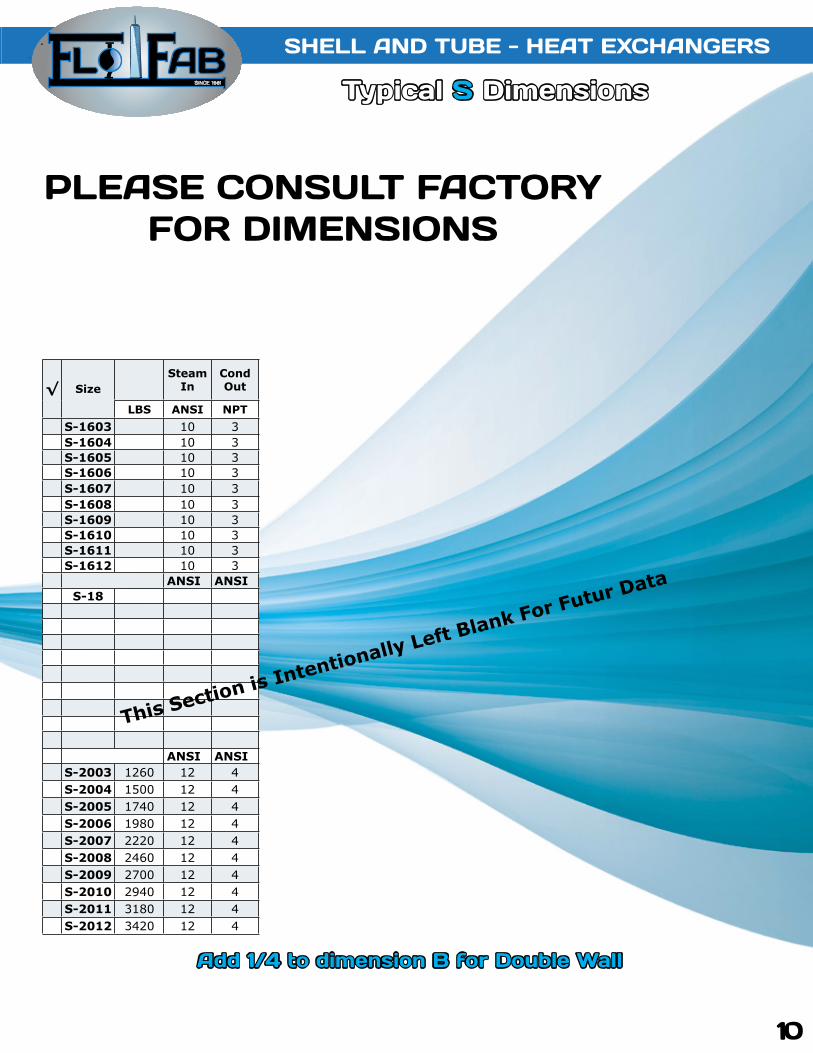
√ SizeSteam
InCond Out
LBS ANSI NPTS-1603 10 3S-1604 10 3S-1605 10 3S-1606 10 3S-1607 10 3S-1608 10 3S-1609 10 3S-1610 10 3S-1611 10 3S-1612 10 3
ANSI ANSIS-18
ANSI ANSIS-2003 1260 12 4S-2004 1500 12 4S-2005 1740 12 4S-2006 1980 12 4S-2007 2220 12 4S-2008 2460 12 4S-2009 2700 12 4S-2010 2940 12 4S-2011 3180 12 4S-2012 3420 12 4
10
This Section is Intentionally Left Blank For Futur Data
Add 1/4 to dimension B for Double Wall
PLEASE CONSuLT FACTORY FOR DIMENSIONS

SINCE 1981
SHELL AND TuBE - HEAT EXCHANGERS
Typical S Dimensions
√ SizeSteam
InCond Out
LBS ANSI ANSIS-22
S-2403 1985 10 3S-2404 2248 10 3S-2405 2518 12 4S-2406 2845 12 4S-2407 3272 14 4S-2408 3828 16 6S-2409 4632 16 6S-2410 5095 16 6S-2411 5570 18 8S-2412 6044 18 8
S-2603 2510 10 3S-2604 2810 12 4S-2605 3120 12 4S-2606 3495 14 4S-2607 3950 16 6S-2608 4540 16 6S-2609 5310 18 6S-2610 6425 18 6S-2611 7030 18 6S-2612 7635 20 6
11
This Section is Intentionally Left Blank For Futur Data
Add 1/4 to dimension B for Double Wall
PLEASE CONSuLT FACTORY FOR DIMENSIONS
PLEASE CONSuLT FACTORY FOR DIMENSIONS

SINCE 1981
SHELL AND TuBE - HEAT EXCHANGERS
Typical S Dimensions Typical S Dimensions
√ SizeSteam
InCond Out
LBS ANSI ANSIS-2803 3130 12 4S-2804 3515 12 4S-2805 3900 14 4S-2806 4370 16 6S-2807 4935 16 6S-2808 5675 18 6S-2809 6640 18 6S-2810 8035 20 6S-2811 8790 22 8S-2812 9540 22 8
DESIGN CONDITIONS ( S16 to S28 ) Notes:Units fabricated and tested in accor-dance with ASME Section VIII Division 1.Heat exchanger supports provided separately. All dimensions + / - 0.125”.
TUBE SIDE SHELL SIDEDESIGN PRESSURE 150 Psig 150 Psig
TEST PRESSURE 195 Psig 195 PsigDESIGN TEMPERATURE 375 °F 375 °F
MIN METAL: TEMPERATURE 35 °F 35 °F
SHELL AND TuBE - HEAT EXCHANGERS
12
Add 1/4 to dimension B for Double Wall
PLEASE CONSuLT FACTORY FOR DIMENSIONS

SINCE 1981
SHELL AND TuBE - HEAT EXCHANGERS
Typical SE Dimensions
DESIGN CONDITIONS (SE4, SE6 and SE8 ) Notes:Units fabricated and tested in accor-dance with ASME Section VIII Division 1.Heat exchanger supports provided separately. All dimensions + / - 0.125”.
TUBE SIDE SHELL SIDEDESIGN PRESSURE 150 Psig 150 Psig
TEST PRESSURE 195 Psig 195 PsigDESIGN TEMPERATURE 375 °F 375 °F
MIN METAL: TEMPERATURE 35 °F 35 °F
√ SizeSteam
InCond Out
LBS NPT NPTSE-04
SE-0602 132 1.5 1SE-0603 159 2 1SE-0604 186 2.5 1SE-0605 213 2.5 1SE-0606 240 3 1SE-0607 267 3 1SE-0608 294 3 1
SE-0802 220 2 1SE-0803 260 2.5 1SE-0804 300 3 1SE-0805 340 4* 1SE-0806 380 4* 1.25SE-0807 420 4* 1.25SE-0808 460 6* 1.25SE-0809 500 6* 1.25SE-0810 540 6* 1.25
13
This Section is Intentionally Left Blank For Futur Data
Add 1/4 to dimension B for Double Wall
PLEASE CONSuLT FACTORY FOR DIMENSIONS
PLEASE CONSuLT FACTORY FOR DIMENSIONS

SINCE 1981 Typical SE Dimensions
√ SizeSteam
InCond Out
LBS ANSI NPTSE-10
SE-12
SE-1403 695 6 2SE-1404 815 6 2SE-1405 935 8 2.5SE-1406 1055 8 2.5SE-1407 1180 8 2.5SE-1408 1300 8 2.5SE-1409 1420 8 2.5SE-1410 1540 8 2.5SE-1411 1661 8 2.5SE-1412 1781 8 2.5
DESIGN CONDITIONS (S10, S12 and S14) Notes:Units fabricated and tested in accor-dance with ASME Section VIII Division 1.Heat exchanger supports provided separately. All dimensions + / - 0.125”.
TUBE SIDE SHELL SIDEDESIGN PRESSURE 150 Psig 150 Psig
TEST PRESSURE 195 Psig 195 PsigDESIGN TEMPERATURE 375 °F 375 °F
MIN METAL: TEMPERATURE 35 °F 35 °F
SHELL AND TuBE - HEAT EXCHANGERS
Typical SE Dimensions
14
This Section is Intentionally Left Blank For Futur Data
Add 1/4 to dimension B for Double Wall
PLEASE CONSuLT FACTORY FOR DIMENSIONS

SINCE 1981
SHELL AND TuBE - HEAT EXCHANGERS
Typical SE Dimensions
DESIGN CONDITIONS ( SE16, SE18 and SE20 ) Notes:Units fabricated and tested in accor-dance with ASME Section VIII Division 1.Heat exchanger supports provided separately. All dimensions + / - 0.125”.
TUBE SIDE SHELL SIDEDESIGN PRESSURE - Psig - Psig
TEST PRESSURE - Psig - PsigDESIGN TEMPERATURE - °F - °F
MIN METAL: TEMPERATURE - °F - °F
√ SizeSteam
InCond Out
LBS ANSI NPTSE-16
SE-18
SE-20
15
This Section is Intentionally Left Blank For Futur Data
Add 1/4 to dimension B for Double Wall
PLEASE CONSuLT FACTORY FOR DIMENSIONS
PLEASE CONSuLT FACTORY FOR DIMENSIONS

SINCE 1981 Typical SE Dimensions
DESIGN CONDITIONS ( SE22, SE24 and SE26 ) Notes:Units fabricated and tested in accor-dance with ASME Section VIII Division 1.Heat exchanger supports provided separately. All dimensions + / - 0.125”.
TUBE SIDE SHELL SIDEDESIGN PRESSURE - Psig - Psig
TEST PRESSURE - Psig - PsigDESIGN TEMPERATURE - °F - °F
MIN METAL: TEMPERATURE - °F - °F
√ SizeSteam
InCond Out
LBS ANSI NPTSE-22
SE-24
SE-26
SHELL AND TuBE - HEAT EXCHANGERS
Typical SE Dimensions
16
This Section is Intentionally Left Blank For Futur Data
Add 1/4 to dimension B for Double Wall
PLEASE CONSuLT FACTORY FOR DIMENSIONS

SINCE 1981
SHELL AND TuBE - HEAT EXCHANGERS
Typical SE Dimensions
DESIGN CONDITIONS (SE28) Notes:Units fabricated and tested in accor-dance with ASME Section VIII Division 1.Heat exchanger supports provided separately. All dimensions + / - 0.125”.
TUBE SIDE SHELL SIDEDESIGN PRESSURE 150 Psig 150 Psig
TEST PRESSURE 195 Psig 195 PsigDESIGN TEMPERATURE 375 °F 375 °F
MIN METAL: TEMPERATURE 35 °F 35 °F
√ SizeSteam
InCond Out
LBS ANSI NPTSE-28
17
This Section is Intentionally Left Blank For Futur Data
Add 1/4 to dimension B for Double Wall
PLEASE CONSuLT FACTORY FOR DIMENSIONS
PLEASE CONSuLT FACTORY FOR DIMENSIONS

SINCE 1981
SHELL AND TuBE - HEAT EXCHANGERS
Typical W Dimensions
√ SizeSteam
InCond Out
LBS NPT NPTW-04
W-0602 132 2 2W-0603 159 2 2W-0604 186 2 2W-0605 213 2 2W-0606 240 2 2W-0607 267 2 2W-0608 294 2 2W-0609 321 2 2W-0610 348 2 2W-0611 375 2 2W-0612 402 2 2
W-0802 220 3 3W-0803 260 3 3W-0804 300 3 3W-0805 340 3 3W-0806 380 3 3W-0807 420 3 3W-0808 460 3 3W-0809 500 3 3W-0810 540 3 3W-0811 580 3 3W-0812 620 3 3
Typical SE Dimensions
18
This Section is Intentionally Left Blank For Futur Data
Add 1/4 to dimension B for Double Wall
PLEASE CONSuLT FACTORY FOR DIMENSIONS

SINCE 1981
SHELL AND TuBE - HEAT EXCHANGERS
Typical W Dimensions
√ SizeSHELL
INSHELL OUT
LBS ANSI ANSIW-1003 400 4 4W-1004 460 4 4W-1005 520 4 4W-1006 580 4 4W-1007 640 4 4W-1008 700 4 4W-1009 760 4 4W-1010 820 4 4W-1011 880 4 4W-1012 940 4 4
W-1203 400 4 4W-1204 460 4 4W-1205 520 4 4W-1206 580 4 4W-1207 640 4 4W-1208 700 4 4W-1209 760 4 4W-1210 820 4 4W-1211 880 4 4W-1212 940 4 4
DESIGN CONDITIONS ( W4 to W12) Notes:Units fabricated and tested in accor-dance with ASME Section VIII Division 1.Heat exchanger supports provided separately. All dimensions + / - 0.125”.
TUBE SIDE SHELL SIDEDESIGN PRESSURE 125 Psig 150 Psig
TEST PRESSURE 163 Psig 195 PsigDESIGN TEMPERATURE 375 °F 375 °F
MIN METAL: TEMPERATURE 35 °F 35 °F
19
Add 1/4 to dimension B for Double Wall
PLEASE CONSuLT FACTORY FOR DIMENSIONS
PLEASE CONSuLT FACTORY FOR DIMENSIONS

SINCE 1981
SHELL AND TuBE - HEAT EXCHANGERS
Typical W Dimensions
√ SizeSHELL
INSHELL OUT
LBS ANSI ANSIW-1403 695 6 6W-1404 815 6 6W-1405 935 6 6W-1406 1055 6 6W-1407 1180 6 6W-1408 1300 6 6W-1409 1420 6 6W-1410 1540 6 6W-1411 1661 6 6W-1412 1781 6 6
W-16
W-1803 1050 6 6W-1804 1250 6 6W-1805 1450 6 6W-1806 1650 6 6W-1807 1850 6 6W-1808 2050 6 6W-1809 2250 6 6W-1810 2450 6 6W-1811 2650 6 6W-1812 2850 6 6W-1813 3050 6 6W-1814 3250 6 6W-1815 3450 6 6
SHELL AND TuBE - HEAT EXCHANGERS
Typical W Dimensions
20
This Section is Intentionally Left Blank For Futur Data
Add 1/4 to dimension B for Double Wall
PLEASE CONSuLT FACTORY FOR DIMENSIONS

SINCE 1981
√ SizeSHELL
INSHELL OUT
LBS ANSI ANSIW-20
W-22
W-24
SHELL AND TuBE - HEAT EXCHANGERS
Typical W Dimensions
21
This Section is Intentionally Left Blank For Futur Data
Add 1/4 to dimension B for Double Wall
PLEASE CONSuLT FACTORY FOR DIMENSIONS
PLEASE CONSuLT FACTORY FOR DIMENSIONS
SINCE 1981
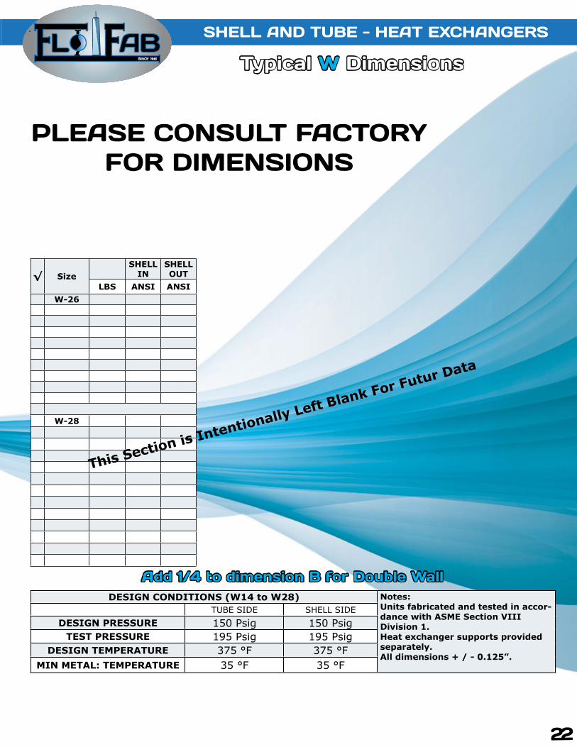
DESIGN CONDITIONS (W14 to W28) Notes:Units fabricated and tested in accor-dance with ASME Section VIII Division 1.Heat exchanger supports provided separately. All dimensions + / - 0.125”.
TUBE SIDE SHELL SIDEDESIGN PRESSURE 150 Psig 150 Psig
TEST PRESSURE 195 Psig 195 PsigDESIGN TEMPERATURE 375 °F 375 °F
MIN METAL: TEMPERATURE 35 °F 35 °F
Typical W Dimensions
√ SizeSHELL
INSHELL OUT
LBS ANSI ANSIW-26
W-28
SHELL AND TuBE - HEAT EXCHANGERS
Typical W Dimensions
22
This Section is Intentionally Left Blank For Futur Data
Add 1/4 to dimension B for Double Wall
PLEASE CONSuLT FACTORY FOR DIMENSIONS
SINCE 1981
SHELL AND TuBE - HEAT EXCHANGERS
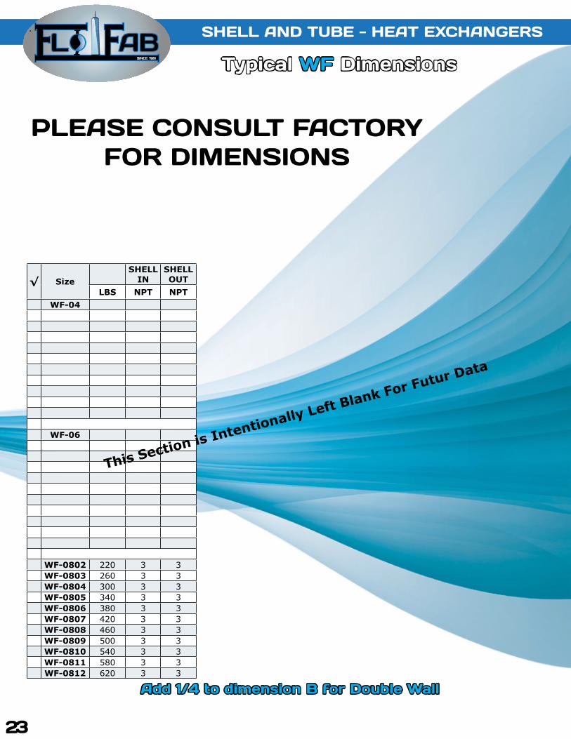
Typical WF Dimensions
√ SizeSHELL
INSHELL OUT
LBS NPT NPTWF-04
WF-06
WF-0802 220 3 3WF-0803 260 3 3WF-0804 300 3 3WF-0805 340 3 3WF-0806 380 3 3WF-0807 420 3 3WF-0808 460 3 3WF-0809 500 3 3WF-0810 540 3 3WF-0811 580 3 3WF-0812 620 3 3
23
This Section is Intentionally Left Blank For Futur Data
Add 1/4 to dimension B for Double Wall
PLEASE CONSuLT FACTORY FOR DIMENSIONS
PLEASE CONSuLT FACTORY FOR DIMENSIONS

SINCE 1981
SHELL AND TuBE - HEAT EXCHANGERS SHELL AND TuBE - HEAT EXCHANGERS
Typical WF Dimensions Typical WF Dimensions
√ SizeSHELL
INSHELL OUT
LBS NPT NPTWF-10
WF-12
WF-14
24
This Section is Intentionally Left Blank For Futur Data
Add 1/4 to dimension B for Double Wall
PLEASE CONSuLT FACTORY FOR DIMENSIONS

SINCE 1981
DESIGN CONDITIONS ( WF04 to WF18) Notes:Units fabricated and tested in accor-dance with ASME Section VIII Division 1.Heat exchanger supports provided separately. All dimensions + / - 0.125”.
TUBE SIDE SHELL SIDEDESIGN PRESSURE 150 Psig 150 Psig
TEST PRESSURE 195 Psig 195 PsigDESIGN TEMPERATURE 375 °F 375 °F
MIN METAL: TEMPERATURE 35 °F 35 °F
SHELL AND TuBE - HEAT EXCHANGERS
Typical WF Dimensions
√ SizeSHELL
INSHELL OUT
LBS NPT NPTWF-16
WF-18
25
This Section is Intentionally Left Blank For Futur Data
Add 1/4 to dimension B for Double Wall
PLEASE CONSuLT FACTORY FOR DIMENSIONS
PLEASE CONSuLT FACTORY FOR DIMENSIONS

SINCE 1981
SHELL AND TuBE - HEAT EXCHANGERS
Typical WF Dimensions
SHELL AND TuBE - HEAT EXCHANGERS
Typical WF Dimensions
√ SizeSHELL
INSHELL OUT
LBS NPT NPTWF-20
WF-22
WF-24
26
This Section is Intentionally Left Blank For Futur Data
Add 1/4 to dimension B for Double Wall
PLEASE CONSuLT FACTORY FOR DIMENSIONS

SINCE 1981
DESIGN CONDITIONS ( WF20 to WF28) Notes:Units fabricated and tested in accor-dance with ASME Section VIII Division 1.Heat exchanger supports provided separately. All dimensions + / - 0.125”.
TUBE SIDE SHELL SIDEDESIGN PRESSURE 150 Psig 150 Psig
TEST PRESSURE 195 Psig 195 PsigDESIGN TEMPERATURE 375 °F 375 °F
MIN METAL: TEMPERATURE 35 °F 35 °F
SHELL AND TuBE - HEAT EXCHANGERS
Typical WF Dimensions
√ SizeSHELL
INSHELL OUT
LBS NPT NPTWF-26
WF-28
27
This Section is Intentionally Left Blank For Futur Data
Add 1/4 to dimension B for Double Wall
PLEASE CONSuLT FACTORY FOR DIMENSIONS

SINCE 1981
SHELL AND TuBE - HEAT EXCHANGERS
Typical WF DimensionsNEW GENERATION
Typical S Dimensions
√ Model # Cast Iron Heads (in) Dimensions (in)2 Pass and 4 Pass
Htg.Surf.2 Pass 4 Pass 2 Pass 4 Pass
4 inch R1 K1 FNTP R3 K2 R2 H D F M E B A L N1 N2 (sq.ft)S042041 S044041
2 1/2 1 1/2 2 3/8 1 7/8 2 7/8 4 1/2 9 5
19 1/2
4
4 24 1/2
2’’NPT 1’’NPT
4.7S042042 S044042 31 1/2 4 36 1/2 6.9S042043 S044043 43 1/2 4 48 1/2 9.1S042044 S044044 55 1/2 4 60 1/2 11.3S042045 S044045 67 1/2 3 7/8 72 1/2 13.6S042046 S044046 79 1/2 3 3/4 84 1/2 15.8S042047 S044047 91 1/2 3 3/4 96 1/2 18S042048 S044048 103 1/2 3 3/4 108 1/2 20.3S042049 S044049 115 1/2 3 3/4 120 1/2 22.5 6 inch
S062061 S064061
4 2 3 3/4 1/2 1 1/4 3 7/16 6 5/8 11 5
18 1/2
4 7/8
4 7/8 25
3’’NPT 1’’NPT
10.7
S062062 S064062 30 1/2 4 7/8 37 15.9S062063 S064063 42 1/2 5 3/4 49 21.1S062064 S064064 54 1/2 5 3/4 61 26.3S062065 S064065 66 1/2 5 9/16 73 31.5S062066 S064066 78 1/2 5 9/16 85 36.7S062067 S064067 90 1/2 5 9/16 97 41.9S062068 S064068 102 1/2 5 9/16 109 47.1S062069 S064069 114 1/2 5 9/16 121 52.3 8 inchS082081 S084081
5 3 4 2 2 4 1/4 8 5/8 13 1/2 8
18
6
6 24 3’’NPT 1’’NPT 14.7S082082 S084082 30 6 7/8 36 3’’NPT 1’’NPT 22.7S082083 S084083 42 6 13/16 48 3’’NPT 1’’NPT 30.7S082084 S084084 54 8 7/8 60 4’’ Flange 1’’NPT 38.7S082085 S084085 66 8 7/8 72 4’’ Flange 1 1/4’’NPT 46.6S082086 S084086 78 8 7/8 84 4’’ Flange 1 1/4’’NPT 54.6S082087 S084087 90 8 7/8 96 6’’ Flange 1 1/4’’NPT 62.6S082088 S084088 102 8 7/8 108 6’’ Flange 1 1/4’’NPT 70.6S082089 S084089 114 8 7/8 120 6’’ Flange 1 1/4’’NPT 78.6 10 inchS102101 S104101
6 1/4 3 5 1/2 3 2 1/4 4 7/8 10 3/4 16 8
17
7 1/8
7 15/16 24 4’’ Flange 1’’NPT 23.7S102102 S104102 29 10 36 4’’ Flange 1’’NPT 37.7S102103 S104103 41 10 48 4’’ Flange 1 1/4’’NPT 51.5S102104 S104104 53 10 60 6’’ Flange 1 1/4’’NPT 65.5S102105 S104105 65 10 72 6’’ Flange 1 1/2’’NPT 79.4S102106 S104106 77 10 84 6’’ Flange 1 1/2’’NPT 93.3S102107 S104107 88 1/2 10 96 6’’ Flange 2’’NPT 107.2S102108 S104108 100 1/2 10 108 6’’ Flange 2’’NPT 121.1S102109 S104109 112 1/2 10 120 6’’ Flange 2’’NPT 135.1
SHELL AND TuBE - HEAT EXCHANGERS
28Not Available for Double Wall

SINCE 1981
√ Model # Heads (in) Dimensions (in)2 Pass and 4 Pass
Htg.Surf.2 Pass 4 Pass 2 Pass 4 Pass
12 inch R1 K1 FNTP R2 K2 C H D F M E B A L N1 N2 (sq.ft)S122121 S124121
24 4’’ Flange 12 3’’
Flange 10 1/8 14 5/8 12 3/4 19 10
29 8 1/8
11
36 1/4 4’’ Flange 1 1/4’’NPT 58.6S122122 S124122 41 8 1/8 48 1/4 6’’ Flange 1 1/4’’NPT 79S122123 S124123 53 8 1/8 60 1/4 6’’ Flange 1 1/2’’NPT 99.5S122124 S124124 65 8 1/8 72 1/4 6’’ Flange 2’’NPT 119.9S122125 S124125 77 8 1/8 84 1/4 8’’ Flange 2’’NPT 140.3S122126 S124126 88 9 96 1/4 8’’ Flange 2 1/2’’NPT 160.8S122127 S124127 100 9 108 1/4 8’’ Flange 2 1/2’’NPT 181.2S122128 S124128 112 9 120 1/4 8’’ Flange 2 1/2’’NPT 201.6 14 inchS142141 S144141
26 6’’ Flange 13 4’’
Flange 11 5/8 16 5/8 14 21 10
29 8 3/4
12
37 1/4 6’’ Flange 1 1/4’’NPT 75.7S142142 S144142 40 1/2 8 3/4 49 1/4 6’’ Flange 2’’NPT 102.4S142143 S144143 52 1/2 8 3/4 61 1/4 6’’ Flange 2’’NPT 129.1S142144 S144144 64 1/2 8 3/4 73 1/4 8’’ Flange 2’’NPT 155.8S142145 S144145 76 9 5/8 85 1/4 8’’ Flange 2 1/2’’NPT 182.5S142146 S144146 88 9 5/8 97 1/4 8’’ Flange 2 1/2’’NPT 209.2S142147 S144147 100 9 5/8 109 1/4 10’’ Flange 2 1/2’’NPT 236S142148 S144148 112 9 5/8 121 1/4 10’’ Flange 3’’NPT 262.7 16 inchS162161 S164161
28 1/2 6’’ Flange 14 1/4 4’’
Flange 12 1/8 17 3/8 16 23 1/2 11
28 1/2 9 3/4
13
37 6’’ Flange 1 1/2’’NPT 104.5S162162 S164162 40 9 3/4 49 6’’ Flange 2’’NPT 141.4S162163 S164163 52 10 5/8 61 8’’ Flange 2 1/2’’NPT 178.4S162164 S164164 64 10 5/8 73 8’’ Flange 2 1/2’’NPT 215.3S162165 S164165 76 10 5/8 85 10’’ Flange 2 1/2’’NPT 252.2S162166 S164166 87 1/2 10 5/8 97 10’’ Flange 3’’NPT 289.1S162167 S164167 99 1/2 10 5/8 109 10’’ Flange 3’’NPT 326S162168 S164168 111 1/2 10 5/8 121 10’’ Flange 3’’NPT 363 18 inchS182181 S184181
30 6’’ Flange 15 4’’
Flange 12 3/4 18 18 25 13
27 1/2 10 3/4
14
36 1/2 6’’ Flange 2’’NPT 130.7S182182 S184182 39 1/2 10 3/4 48 1/2 8’’ Flange 2’’NPT 177S182183 S184183 51 11 5/8 60 1/2 8’’ Flange 2 1/2’’NPT 223.4S182184 S184184 62 1/2 11 5/8 72 1/2 10’’ Flange 3’’NPT 269.7S182185 S184185 74 1/2 11 5/8 84 1/2 10’’ Flange 3’’NPT 316.1S182186 S184186 86 1/2 11 5/8 96 1/2 10’’ Flange 3’’NPT 362.4S182187 S184187 98 1/2 11 5/8 108 1/2 10’’ Flange 3’’NPT 408.8S182188 S184188 110 1/2 12 120 1/2 10’’ Flange 4’’Flange 455.1
SHELL AND TuBE - HEAT EXCHANGERS
Typical S DimensionsNEW GENERATION
29
Not Available for Double Wall

SINCE 1981
SHELL AND TuBE - HEAT EXCHANGERS
Typical S Dimensions
√ Model # Heads (in) Dimensions (in)2 Pass and 4 Pass
Htg.Surf.2 Pass 4 Pass 2 Pass 4 Pass
20 inch R1 K1 FNTP R2 K2 C H D F M E B A L N1 N2 (sq.ft)S202201 S204201
32 1/2 6’’ Flange 16 1/4 4’’
Flange 14 1/8 19 5/8 20 27 1/2 13
27 1/2 15 15 36 3/4 8’’ Flange 8’’ Flange 163.9S202202 S204202 39 15 15 48 3/4 8’’ Flange 8’’ Flange 223.6S202203 S204203 50 1/2 15 15 60 3/4 10’’ Flange 10’’ Flange 283.3S202204 S204204 62 1/2 15 15 72 3/4 10’’ Flange 10’’ Flange 343S202205 S204205 74 1/2 15 15 84 3/4 12’’ Flange 12’’ Flange 402.7S202206 S204206 86 1/2 15 15 96 3/4 12’’ Flange 12’’ Flange 462.4S202207 S204207 98 1/2 15 15 108 3/4 12’’ Flange 12’’ Flange 522.2S202208 S204208 110 1/2 17 17 120 3/4 14’’ Flange 14’’ Flange 581.9 22 inchS222221 S224221
35 10’’ Flange 17 1/4 8’’
Flange 17 24 1/2 22 29 1/2 14
25 3/8 17 17 38 3/8 12’’ Flange 12’’ Flange 193.5S222222 S224222 37 3/8 17 17 50 3/8 12’’ Flange 12’’ Flange 265S222223 S224223 49 3/8 17 17 62 3/8 12’’ Flange 12’’ Flange 336.5S222224 S224224 61 3/8 17 17 74 3/8 12’’ Flange 12’’ Flange 408S222225 S224225 73 3/8 17 17 86 3/8 12’’ Flange 12’’ Flange 479.5S222226 S224226 85 3/8 17 17 98 3/8 12’’ Flange 12’’ Flange 551S222227 S224227 97 3/8 18 18 110 3/8 14’’ Flange 14’’ Flange 622.5S222228 S224228 109 3/8 18 18 122 3/8 14’’ Flange 14’’ Flange 694 24 inchS242241 S244241
37 1/2 10’’ Flange 18 1/2 8’’
Flange 17 7/8 25 5/8 24 32 14
25 18 18 38 12’’ Flange 12’’ Flange 236S242242 S244242 37 18 18 50 12’’ Flange 12’’ Flange 324S242243 S244243 49 18 18 62 12’’ Flange 12’’ Flange 412S242244 S244244 61 18 18 74 12’’ Flange 12’’ Flange 500S242245 S244245 73 18 18 86 12’’ Flange 12’’ Flange 588S242246 S244246 85 18 18 98 12’’ Flange 12’’ Flange 676S242247 S244247 97 19 19 110 14’’ Flange 14’’ Flange 764S242248 S244248 109 19 19 122 14’’ Flange 14’’ Flange 852 26 inchS262261 S264261
37 12’’ Flange 18 1/4 8’’
Flange 17 24 3/4 26 34 1/4 15
23 3/4 20 20 36 14’’ Flange 14’’ Flange 288.6S262262 S264262 25 3/4 20 20 48 14’’ Flange 14’’ Flange 393.4S262263 S264263 47 3/4 20 20 60 14’’ Flange 14’’ Flange 500.2S262264 S264264 59 3/4 20 20 72 14’’ Flange 14’’ Flange 607S262265 S264265 71 3/4 20 20 84 14’’ Flange 14’’ Flange 713.8S262266 S264266 83 3/4 20 20 96 14’’ Flange 14’’ Flange 820.6S262267 S264267 95 3/4 21 21 108 16’’ Flange 16’’ Flange 927.4S262268 S264268 107 3/4 21 21 120 16’’ Flange 16’’ Flange 1034.4 30 inchS302301 S304301
42 14’’ Flange 20 3/4 10’’
Flange 19 5/8 28 7/8 30 38 3/4 16
23 22 22 38 1/2 16’’ Flange 16’’ Flange 377.6S302302 S304302 35 22 22 50 1/2 16’’ Flange 16’’ Flange 520.5S302303 S304303 47 22 22 62 1/2 16’’ Flange 16’’ Flange 663.4S302304 S304304 59 22 22 74 1/2 16’’ Flange 16’’ Flange 806.3S302305 S304305 71 22 22 86 1/2 16’’ Flange 16’’ Flange 949.2S302306 S304306 83 22 22 98 1/2 16’’ Flange 16’’ Flange 1092S302307 S304307 95 22 22 110 1/2 18’’ Flange 18’’ Flange 1235S302308 S304308 107 22 22 122 1/2 18’’ Flange 18’’ Flange 1378
Typical S Dimensions
SHELL AND TuBE - HEAT EXCHANGERS
NEW GENERATION
30
Not Available for Double Wall

SINCE 1981 Typical W Dimensions
√ Model # Cast Iron Heads (in) Dimensions (in)2 Pass and 4 Pass
Htg.Surf.2 Pass 4 Pass 2 Pass 4 Pass
4 inch R1 K1 FNTP R3 K2 R2 H D F M E B A L N1 N2 (sq.ft)W042041 W044041
2 1/2 1 1/2 2 3/8 1 7/8 2 7/8 4 1/2 9 5
19 1/2
3 3/4 3 3/4
24 1/2
1 1/2’’NPT 1 1/2’’NPT
4.7W042042 W044042 31 1/2 36 1/2 6.9W042043 W044043 43 1/2 48 1/2 9.1W042044 W044044 55 1/2 60 1/2 11.3W042045 W044045 67 1/2 72 1/2 13.6W042046 W044046 79 1/2 84 1/2 15.8W042047 W044047 91 1/2 96 1/2 18W042048 W044048 103 1/2 108 1/2 20.3W042049 W044049 115 1/2 120 1/2 22.5 6 inch
W062061 W064061
4 2 3 3/4 1 1/2 1 1/4 3 7/16 6 5/8 11 5
18 1/2
4 7/8 4 7/8
25
2 1/2’’NPT 2 1/2’’NPT
10.7
W062062 W064062 30 1/2 37 15.9W062063 W064063 42 1/2 49 21.1W062064 W064064 54 1/2 61 26.3W062065 W064065 66 1/2 73 31.5W062066 W064066 78 1/2 85 36.7W062067 W064067 90 1/2 97 41.9W062068 W064068 102 1/2 109 47.1W062069 W064069 114 1/2 121 52.3 8 inchW082081 W084081
5 3 4 2 2 4 1/4 8 5/8 13 1/2 8
18
7 3/8 7 3/8
24
4’’Flange 4’’Flange
14.7W082082 W084082 30 36 22.7W082083 W084083 42 48 30.7W082084 W084084 54 60 38.7W082085 W084085 66 72 40.6W082086 W084086 78 84 54.6W082087 W084087 90 96 62.6W082088 W084088 102 108 70.6W082089 W084089 114 120 78.6 10 inchW102101 W104101
6 1/4 3 5 1/2 3 2 1/4 4 7/8 10 3/4 16 8
17
8 1/2 8 1/2
24
4’’Flange 4’’Flange
23.7W102102 W104102 29 36 37.7W102103 W104103 41 48 51.5W102104 W104104 53 60 65.5W102105 W104105 65 72 79.4W102106 W104106 77 84 93.3W102107 W104107 88 1/2 96 107.2W102108 W104108 100 1/2 108 121.1W102109 W104109 112 1/2 120 135.1
SHELL AND TuBE - HEAT EXCHANGERS
NEW GENERATION
31Not Available for Double Wall
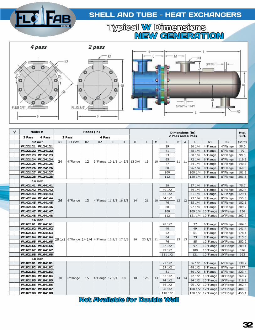
SINCE 1981 Typical W Dimensions
√ Model # Heads (in) Dimensions (in)2 Pass and 4 Pass
Htg.Surf.2 Pass 4 Pass 2 Pass 4 Pass
12 inch R1 K1 FNTP R2 K2 C H D F M E B A L N1 N2 (sq.ft)W122121 W124121
24 4’’Flange 12 3’’Flange 10 1/8 14 5/8 12 3/4 19 10
29
11 11
36 1/4 4’’Flange 4’’Flange 58.6W122122 W124122 41 48 1/4 6’’Flange 6’’Flange 79W122123 W124123 53 60 1/4 6’’Flange 6’’Flange 99.5W122124 W124124 65 72 1/4 6’’Flange 6’’Flange 119.9W122125 W124125 77 84 1/4 8’’Flange 8’’Flange 140.3W122126 W124126 88 96 1/4 8’’Flange 8’’Flange 160.8W122127 W124127 100 108 1/4 8’’Flange 8’’Flange 181.2W122128 W124128 112 120 1/4 8’’Flange 8’’Flange 201.6 14 inchW142141 W144141
26 6’’Flange 13 4’’Flange 11 5/8 16 5/8 14 21 10
29
12 12
37 1/4 6’’Flange 6’’Flange 75.7W142142 W144142 40 1/2 49 1/4 6’’Flange 6’’Flange 102.4W142143 W144143 52 1/2 61 1/4 6’’Flange 6’’Flange 129.1W142144 W144144 64 1/2 73 1/4 8’’Flange 8’’Flange 155.8W142145 W144145 76 85 1/4 8’’Flange 8’’Flange 182.5W142146 W144146 88 97 1/4 8’’Flange 8’’Flange 209.2W142147 W144147 100 109 1/4 10’’Flange 10’’Flange 236W142148 W144148 112 121 1/4 10’’Flange 10’’Flange 262.7 16 inchW162161 W164161
28 1/2 6’’Flange 14 1/4 4’’Flange 12 1/8 17 3/8 16 23 1/2 11
28 1/2
13 13
37 6’’Flange 6’’Flange 104.5W162162 W164162 40 49 6’’Flange 6’’Flange 141.4W162163 W164163 52 61 8’’Flange 8’’Flange 178.4W162164 W164164 64 73 8’’Flange 8’’Flange 215.3W162165 W164165 76 85 10’’Flange 10’’Flange 252.2W162166 W164166 87 1/2 97 10’’Flange 10’’Flange 289.1W162167 W164167 99 1/2 109 10’’Flange 10’’Flange 326W162168 W164168 111 1/2 121 10’’Flange 10’’Flange 363 18 inchW182181 W184181
30 6’’Flange 15 4’’Flange 12 3/4 18 18 25 13
27 1/2
14 14
36 1/2 6’’Flange 6’’Flange 130.7W182182 W184182 39 1/2 48 1/2 8’’Flange 8’’Flange 177W182183 W184183 51 60 1/2 8’’Flange 8’’Flange 223.4W182184 W184184 62 1/2 72 1/2 10’’Flange 10’’Flange 269.7W182185 W184185 74 1/2 84 1/2 10’’Flange 10’’Flange 316.1W182186 W184186 86 1/2 96 1/2 10’’Flange 10’’Flange 362.4W182187 W184187 98 1/2 108 1/2 12’’Flange 12’’Flange 408.8W182188 W184188 110 1/2 120 1/2 12’’Flange 12’’Flange 455.1
Typical W DimensionsSHELL AND TuBE - HEAT EXCHANGERS
NEW GENERATION
32
Not Available for Double Wall

SINCE 1981
√ Model # Heads (in) Dimensions (in)2 Pass and 4 Pass
Htg.Surf.2 Pass 4 Pass 2 Pass 4 Pass
20 inch R1 K1 FNTP R2 K2 C H D F M E B A L N1 N2 (sq.ft)W202201 W204201
32 1/2 6’’ Flange 16 1/4 4’’
Flange 14 1/8 19 5/8 20 27 1/2 13
27 1/2 15 15 36 3/4 8’’ Flange 8’’ Flange 163.9W202202 W204202 39 15 15 48 3/4 8’’ Flange 8’’ Flange 223.6W202203 W204203 50 1/2 15 15 60 3/4 10’’ Flange 10’’ Flange 283.3W202204 W204204 62 1/2 15 15 72 3/4 10’’ Flange 10’’ Flange 343W202205 W204205 74 1/2 15 15 84 3/4 12’’ Flange 12’’ Flange 402.7W202206 W204206 86 1/2 15 15 96 3/4 12’’ Flange 12’’ Flange 462.4W202207 W204207 98 1/2 15 15 108 3/4 12’’ Flange 12’’ Flange 522.2W202208 W204208 110 1/2 17 17 120 3/4 14’’ Flange 14’’ Flange 581.9 22 inchW222221 W224221
35 10’’ Flange 17 1/4 8’’
Flange 17 24 1/2 22 29 1/2 14
25 3/8 17 17 38 3/8 12’’ Flange 12’’ Flange 193.5W222222 W224222 37 3/8 17 17 50 3/8 12’’ Flange 12’’ Flange 265W222223 W224223 49 3/8 17 17 62 3/8 12’’ Flange 12’’ Flange 336.5W222224 W224224 61 3/8 17 17 74 3/8 12’’ Flange 12’’ Flange 408W222225 W224225 73 3/8 17 17 86 3/8 12’’ Flange 12’’ Flange 479.5W222226 W224226 85 3/8 17 17 98 3/8 12’’ Flange 12’’ Flange 551W222227 W224227 97 3/8 18 18 110 3/8 14’’ Flange 14’’ Flange 622.5W222228 W224228 109 3/8 18 18 122 3/8 14’’ Flange 14’’ Flange 694 24 inchW242241 W244241
37 1/2 10’’ Flange 18 1/2 8’’
Flange 17 7/8 25 5/8 24 32 14
25 18 18 38 12’’ Flange 12’’ Flange 236W242242 W244242 37 18 18 50 12’’ Flange 12’’ Flange 324W242243 W244243 49 18 18 62 12’’ Flange 12’’ Flange 412W242244 W244244 61 18 18 74 12’’ Flange 12’’ Flange 500W242245 W244245 73 18 18 86 12’’ Flange 12’’ Flange 588W242246 W244246 85 18 18 98 12’’ Flange 12’’ Flange 676W242247 W244247 97 19 19 110 14’’ Flange 14’’ Flange 764W242248 W244248 109 19 19 122 14’’ Flange 14’’ Flange 852 26 inchW262261 W264261
37 12’’ Flange 18 1/4 8’’
Flange 17 24 3/4 26 34 1/4 15
23 3/4 20 20 36 14’’ Flange 14’’ Flange 288.6W262262 W264262 25 3/4 20 20 48 14’’ Flange 14’’ Flange 393.4W262263 W264263 47 3/4 20 20 60 14’’ Flange 14’’ Flange 500.2W262264 W264264 59 3/4 20 20 72 14’’ Flange 14’’ Flange 607W262265 W264265 71 3/4 20 20 84 14’’ Flange 14’’ Flange 713.8W262266 W264266 83 3/4 20 20 96 14’’ Flange 14’’ Flange 820.6W262267 W264267 95 3/4 21 21 108 16’’ Flange 16’’ Flange 927.4W262268 W264268 107 3/4 21 21 120 16’’ Flange 16’’ Flange 1034.4 30 inchW302301 W304301
42 14’’ Flange 20 3/4 10’’
Flange 19 5/8 28 7/8 30 38 3/4 16
23 22 22 38 1/2 16’’ Flange 16’’ Flange 377.6W302302 W304302 35 22 22 50 1/2 16’’ Flange 16’’ Flange 520.5W302303 W304303 47 22 22 62 1/2 16’’ Flange 16’’ Flange 663.4W302304 W304304 59 22 22 74 1/2 16’’ Flange 16’’ Flange 806.3W302305 W304305 71 22 22 86 1/2 16’’ Flange 16’’ Flange 949.2W302306 W304306 83 22 22 98 1/2 16’’ Flange 16’’ Flange 1092W302307 W304307 95 22 22 110 1/2 18’’ Flange 18’’ Flange 1235W302308 W304308 107 22 22 122 1/2 18’’ Flange 18’’ Flange 1378
Typical W Dimensions
SHELL AND TuBE - HEAT EXCHANGERS
33
NEW GENERATION
Not Available for Double Wall

SINCE 1981 Typical W Dimensions
SHELL AND TuBE - HEAT EXCHANGERS
Connection Types
Model-SizeTubeSide
-2 pass-4 pass
Shell SideInlet
Drain Model-SizeTubeSide
-2 pass-4 pass
Shell SideInlet
Drain
S-04 1.25 1 2 1 S-18 6 4 10 4S-06 2 1.5 3 1 S-20 8 6 12 4S-08 3 2 3 1 S-22 10 8 12 4S-10 4 3 6 2 S-24 10 8 14 4S-12 4 4 8 2 S-26 12 8 16 6S-14 4 4 8 2.5 S-28 12 10 18 6S-16 6 4 10 3 S-30 14 10 20 6
Typical S Connection Sizes
Please note that the model W is available upon request.
Design ParametersStandard Optional
DesignPressure
(PSI)
TestPressure
(PSI)
DesignTemperature
(°F)
DesignPressure
(PSI)
DesignTemperature
(°F)Shell 150 300 375 300 421Tubes 150 300 375 400 448
Materials of ConstructionStandard Optional
Shell Steel Stainless Steel(304/316)Tubes Stainless Steel Copper, SS 316, 90/10
Tubesheet Steel CuNiConnections Steel Stainless Steel(304/316)
Head Cast Iron / Steel Stainless Steel(304/316)Gaskets Non-abestos, pressed fiber -
Unit Size Dimensions
H W X HD4 5 1/4 6 15/16 5 1/2 1/26 6 5/16 9 1/4 7 1/2 5/88 7 5/16 11 1/4 9 5/8
10 8 3/8 13 5/8 10 3/412 9 3/8 15 5/8 11 3/414 10 17 12 3/416 12 19 13 3/418 13 21 14 3/420 14 23 14 3/422 17 25 18 7/824 18 27 19 7/826 19 30 20 7/830 21 33 22 7/8
SINCE 1981
34

SINCE 1981
SHELL AND TuBE - HEAT EXCHANGERS
1) CONNECTIONSStandardized sizes for easy assembly. Additional thread and surface protection for clean installation.
3) GASKETSHigh quality com-pressed fibers (reu-sable).
4) HEADStandard cast-iron or steel head for heavy duty services(also available as a spare part).
2) TuBESHEETU-bend tubes ex-panded into tube-sheet allow for tube expansions and contractions due to thermal fluctuations.
5) MOUNTINGSaddles attached with standard units for quick & easy mounting.
6) BAFFLESPunched baffles withminimum clearancesbetween tubes as-sure correct fluid flow and minimized bypass.
7) SHELLWelded shell protec-ted with high quality paint for corrosion resistance.
8) TuBE BuNDLEStainless steel tubes allow for strong, durable performance over a wide range of applications.Unique tube bundle layout minimizes buildup problems at the edges and opti-mizes media flowin the units.
Transfer Solutions
35

SINCE 1981
SHELL AND TuBE - HEAT EXCHANGERS
Heavy Duty ConstructionThe Flo Fab heat exchanger is one of the most rugged heavy duty heat exchangers on the mar-ket. The circular shaped shell and tubes withstand greater pressures than flat plate designs with thinner materials. In accordance with safety codes, corrosion allowances are added to the carbon steel parts for added girth. The tubes are made of various corrosion resistant materials with thicknesses ranging from 20 BWG or 0.035’’ to 16 BWG or 0.065’’ making them at least 50% thicker than other heat transfer surfaces. With fewer gaskets, Flo Fab can withstand higher operating pressures and temperatures than other heat transfer devices.
Human ComfortSDW and WDW double wall designs prevent potable water contact with chemically altered boiler water. The double wall construction provides a positive leak path between the potable water and the heating media should a leak occur in a tube wall. This design conforms to all US building code requirements.
Long Life ExpectancyFlo Fab utilizes U shaped tubes that are anchored at only one end. The tubes are allowed to ex-pand freely in one direction when subject to changing operating temperatures and heat loads. This allows the heat exchanger to cycle with no risk of damage, which ensures a long, trouble-free lite for the product.
Low RiskHeavy duty construction, freely expanding corrosion resistant tubes and minimized use of gas-kets make WesTube° a low risk investment All units come certified by the appropriate safety code (ASME, CRN, etc).
Low MaintenanceFloFab heat exchangers are designed with fewer gaskets, which leads to less maintenance For installations where hard water and scaling may occur, Flo Fab uses larger diameter tubes that can continue to operate and can be easily cleaned. If necessary, a bundle can be swapped out while the other is being serviced.
Lower Pumping CostsThe heat transfer surface in Flo Fab is smooth, resulting in less turbulent flow inside the tubes. This design maximizes heat transfer with reduced pressure drop, which lowers pumping costs.
Application FriendlyFlo Fab is used for heating domestic water, snow melting, pool heating, condensate coo-ling, district heating, radiant heating, comfort heating and other heat transfer systems where pressure separation is needed.
‘‘With over 35 years of experience in pressure vessel design and manufacture, our goal is to provide sustainable energy saving solutions that help make a greener HVAC world.’’
SHELL AND TuBE - HEAT EXCHANGERS
36

SINCE 1981
BL14 BL20 BL26 BL26C
BL50 BL95 BL120 BL190
BL200 BL600 BL100 BL210
BRAZED - HEAT EXCHANGERS
BL SeriesBrazed - Heat Exchangers
37

SINCE 1981
Millimeters (mm)√
Model BL14 BL20 BL26 BL26CWidth 78 76 111 124Height 206 310 310 304Length 9+2.3n 9+2.3n 10+2.36n 13+2.4n
Horizontal Port Distance 42 42 50 70
Vertical Port Distance 172 282 250 250
Max Pressure (Mpa) 3 3 3/4.5 3
Max Flowrate(M3/h) 3.6 3.6 8.1 8.1
Weight(kg) 0.6+0.6n 1.0+0.08n 1.3+0.12n 2.2+0.16n
√Model BL50 BL95 BL120 BL190Width 111 191 246 307
Height 525 616 528 696
Length 10+2.35n 11+2.35n 13+2.36n 13+2.75n
Horizontal Port Distance 50 92 174 179
Vertical Port Distance 466 519 456 567
Max Pressure (Mpa) 3/4.5 3/4.5 3 3
Max Flowrate(M3/h) 12.7 39 42 100
Weight(kg) 2.6+0.19n 7.8+0.36n 7.2+0.52 12.5+0.72n
√Model BL200 BL600 BL100* BL210*Width 321 429 248 322
Height 738 1398 495 739
Length 13+2.7n 22+2.78n 10+2.15n 13+2.55n
Horizontal Port Distance 188 220 157 205,2
Vertical Port Distance 603 1190 405 631
Max Pressure (Mpa) 2.1 1.5 3/4.5 3/4.5
Max Flowrate(M3/h) 100 300 42 100
Weight(kg) 13+0.75n 31.8+1.73 6.5+0.37n 13+0.78n
Inches (in)√
Model BL14 BL20 BL26 BL26CWidth 3,07 2,99 4,37 4,88Height 8,11 12,20 12,20 11,97Length 0.35+0.09n 0.35+0.09n 0.39+0.09n 0.51+0.09!
Horizontal Port Distance 1,65 1,65 1,97 2,76
Vertical Port Distance 6,77 11,10 9,84 9,84
Max Pressure (PSI) 435.11 435.11 435.11/
652.66 435.11
Max Flowrate(USGPM) 15,85 15,85 35,67 35,67
Weight(lbs) 1.32+1.32n 2.20+0.18 2.87+0.26 4.85+0.35
√Model BL50 BL95 BL120 BL190Width 4,37 7,52 9,69 12,09
Height 20,67 24,25 20,79 27,40
Length 0.39+0.09n 0.43+0.09n 0.51+0.09n 0.51+0.11n
Horizontal Port Distance 1,97 3,62 6,85 7,05
Vertical Port Distance 18,35 20,43 17,95 22,32
Max Pressure (PSI)
435.11/652.66
435.11/652.66 435.11 435.11
Max Flowrate(USGPM) 55,92 171,74 184,95 44,35
Weight(lbs) 5.73+0.42n 17.19+0.79n 15.87+1.15n 27.56+1.59n
√Model BL200 BL600 BL100* BL210*Width 12,64 16,89 9,76 12,68
Height 29,06 55,04 19,49 29,09
Length 0.51+0.11n 0.87+0.11n 0.39+0.09n 0.51+0.11n
Horizontal Port Distance 7,40 8,66 6,18 8,08
Vertical Port Distance 23,74 46,85 15,94 24,84
Max Pressure (PSI) 304.58 217.56 435.11/
652.66435.11/652.66
Max Flowrate(USGPM) 440,35 1321,05 184,95 44,35
Weight(lbs) 27.56+1.65n 70.11+3.81n 14.33+0.82n 28.66+1.72n
BRAZED - HEAT EXCHANGERS
BL Series
38
Product DimensionsBL SeriesBrazed - Heat Exchangers

SINCE 1981
39
BRAZED - HEAT EXCHANGERS
Product SpecificationsBL14 Brazed Plate Heat Exchanger
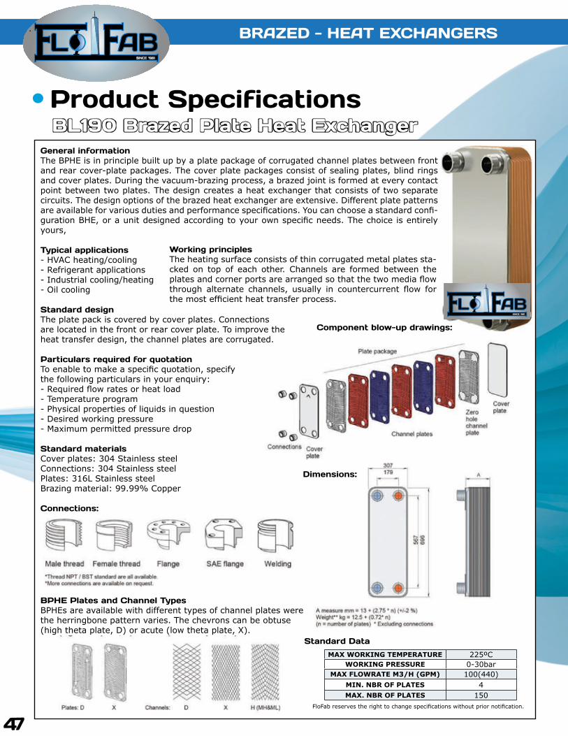
General informationThe BPHE is in principle built up by a plate package of corrugated channel plates between front and rear cover-plate packages. The cover plate packages consist of sealing plates, blind rings and cover plates. During the vacuum-brazing process, a brazed joint is formed at every contact point between two plates. The design creates a heat exchanger that consists of two separate circuits. The design options of the brazed heat exchanger are extensive. Different plate patterns are available for various duties and performance specifications. You can choose a standard confi-guration BHE, or a unit designed according to your own specific needs. The choice is entirely yours,
Typical applications- HVAC heating/cooling- Refrigerant applications- Industrial cooling/heating- Oil cooling
Standard designThe plate pack is covered by cover plates. Connections are located in the front or rear cover plate. To improve the heat transfer design, the channel plates are corrugated.
Particulars required for quotationTo enable to make a specific quotation, specify the following particulars in your enquiry:- Required flow rates or heat load- Temperature program- Physical properties of liquids in question- Desired working pressure- Maximum permitted pressure drop
Standard materialsCover plates: 304 Stainless steelConnections: 304 Stainless steelPlates: 316L Stainless steelBrazing material: 99.99% Copper
Connections:
BPHE Plates and Channel TypesBPHEs are available with different types of channel plates werethe herringbone pattern varies. The chevrons can be obtuse(high theta plate, D) or acute (low theta plate, X).
Component blow-up drawings:
Working principlesThe heating surface consists of thin corrugated metal plates sta-cked on top of each other. Channels are formed between the plates and corner ports are arranged so that the two media flow through alternate channels, usually in countercurrent flow for the most efficient heat transfer process.
Standard DataMAX WORKING TEMPERATURE 225ºC
WORKING PRESSURE 0-30 barMAX FLOWRATE M3/H (GPM) 3.62(15.93)
MIN. NBR OF PLATES 4MAX. NBR OF PLATES 100
FloFab reserves the right to change specifications without prior notification.
Dimensions:

SINCE 1981
BRAZED - HEAT EXCHANGERS
FloFab reserves the right to change specifications without prior notification.
40
Product SpecificationsBL20 Brazed Plate Heat Exchanger
General informationThe BPHE is in principle built up by a plate package of corrugated channel plates between front and rear cover-plate packages. The cover plate packages consist of sealing plates, blind rings and cover plates. During the vacuum-brazing process, a brazed joint is formed at every contact point between two plates. The design creates a heat exchanger that consists of two separate circuits. The design options of the brazed heat exchanger are extensive. Different plate patterns are available for various duties and performance specifications. You can choose a standard confi-guration BHE, or a unit designed according to your own specific needs. The choice is entirely yours,
Typical applications- HVAC heating/cooling- Refrigerant applications- Industrial cooling/heating- Oil cooling
Standard designThe plate pack is covered by cover plates. Connections are located in the front or rear cover plate. To improve the heat transfer design, the channel plates are corrugated.
Particulars required for quotationTo enable to make a specific quotation, specify the following particulars in your enquiry:- Required flow rates or heat load- Temperature program- Physical properties of liquids in question- Desired working pressure- Maximum permitted pressure drop
Standard materialsCover plates: 304 Stainless steelConnections: 304 Stainless steelPlates: 316L Stainless steelBrazing material: 99.99% Copper
Connections:
BPHE Plates and Channel TypesBPHEs are available with different types of channel plates werethe herringbone pattern varies. The chevrons can be obtuse(high theta plate, D) or acute (low theta plate, X).
Component blow-up drawings:
Working principlesThe heating surface consists of thin corrugated metal plates sta-cked on top of each other. Channels are formed between the plates and corner ports are arranged so that the two media flow through alternate channels, usually in countercurrent flow for the most efficient heat transfer process.
Standard DataMAX WORKING TEMPERATURE 225ºC
WORKING PRESSURE 0-30 barMAX FLOWRATE M3/H (GPM) 3.6(15.93)
MIN. NBR OF PLATES 4MAX. NBR OF PLATES 100
FloFab reserves the right to change specifications without prior notification.
Dimensions:

SINCE 1981
41
BRAZED - HEAT EXCHANGERS
Product SpecificationsBL26 Brazed Plate Heat Exchanger
General informationThe BPHE is in principle built up by a plate package of corrugated channel plates between front and rear cover-plate packages. The cover plate packages consist of sealing plates, blind rings and cover plates. During the vacuum-brazing process, a brazed joint is formed at every contact point between two plates. The design creates a heat exchanger that consists of two separate circuits. The design options of the brazed heat exchanger are extensive. Different plate patterns are available for various duties and performance specifications. You can choose a standard confi-guration BHE, or a unit designed according to your own specific needs. The choice is entirely yours,
Typical applications- HVAC heating/cooling- Refrigerant applications- Industrial cooling/heating- Oil cooling
Standard designThe plate pack is covered by cover plates. Connections are located in the front or rear cover plate. To improve the heat transfer design, the channel plates are corrugated.
Particulars required for quotationTo enable to make a specific quotation, specify the following particulars in your enquiry:- Required flow rates or heat load- Temperature program- Physical properties of liquids in question- Desired working pressure- Maximum permitted pressure drop
Standard materialsCover plates: 304 Stainless steelConnections: 304 Stainless steelPlates: 316L Stainless steelBrazing material: 99.99% Copper
Connections:
BPHE Plates and Channel TypesBPHEs are available with different types of channel plates werethe herringbone pattern varies. The chevrons can be obtuse(high theta plate, D) or acute (low theta plate, X).
Component blow-up drawings:
Working principlesThe heating surface consists of thin corrugated metal plates sta-cked on top of each other. Channels are formed between the plates and corner ports are arranged so that the two media flow through alternate channels, usually in countercurrent flow for the most efficient heat transfer process.
Standard DataMAX WORKING TEMPERATURE 225ºC
WORKING PRESSURE 0-30 barMAX FLOWRATE M3/H (GPM) 8.1(35.84)
MIN. NBR OF PLATES 4MAX. NBR OF PLATES 100
FloFab reserves the right to change specifications without prior notification.
Dimensions:

SINCE 1981
BRAZED - HEAT EXCHANGERS
FloFab reserves the right to change specifications without prior notification.
42
Product SpecificationsBL26C Brazed Plate Heat Exchanger
General informationThe BPHE is in principle built up by a plate package of corrugated channel plates between front and rear cover-plate packages. The cover plate packages consist of sealing plates, blind rings and cover plates. During the vacuum-brazing process, a brazed joint is formed at every contact point between two plates. The design creates a heat exchanger that consists of two separate circuits. The design options of the brazed heat exchanger are extensive. Different plate patterns are available for various duties and performance specifications. You can choose a standard confi-guration BHE, or a unit designed according to your own specific needs. The choice is entirely yours,
Typical applications- HVAC heating/cooling- Refrigerant applications- Industrial cooling/heating- Oil cooling
Standard designThe plate pack is covered by cover plates. Connections are located in the front or rear cover plate. To improve the heat transfer design, the channel plates are corrugated.
Particulars required for quotationTo enable to make a specific quotation, specify the following particulars in your enquiry:- Required flow rates or heat load- Temperature program- Physical properties of liquids in question- Desired working pressure- Maximum permitted pressure drop
Standard materialsCover plates: 304 Stainless steelConnections: 304 Stainless steelPlates: 316L Stainless steelBrazing material: 99.99% Copper
Connections:
BPHE Plates and Channel TypesBPHEs are available with different types of channel plates werethe herringbone pattern varies. The chevrons can be obtuse(high theta plate, D) or acute (low theta plate, X).
Component blow-up drawings:
Working principlesThe heating surface consists of thin corrugated metal plates sta-cked on top of each other. Channels are formed between the plates and corner ports are arranged so that the two media flow through alternate channels, usually in countercurrent flow for the most efficient heat transfer process.
Standard DataMAX WORKING TEMPERATURE 225ºC
WORKING PRESSURE 0-30 barMAX FLOWRATE M3/H (GPM) 8.1(35.84)
MIN. NBR OF PLATES 4MAX. NBR OF PLATES 100
FloFab reserves the right to change specifications without prior notification.
Dimensions:

SINCE 1981
43
BRAZED - HEAT EXCHANGERS
Product SpecificationsBL50 Brazed Plate Heat Exchanger
General informationThe BPHE is in principle built up by a plate package of corrugated channel plates between front and rear cover-plate packages. The cover plate packages consist of sealing plates, blind rings and cover plates. During the vacuum-brazing process, a brazed joint is formed at every contact point between two plates. The design creates a heat exchanger that consists of two separate circuits. The design options of the brazed heat exchanger are extensive. Different plate patterns are available for various duties and performance specifications. You can choose a standard confi-guration BHE, or a unit designed according to your own specific needs. The choice is entirely yours,
Typical applications- HVAC heating/cooling- Refrigerant applications- Industrial cooling/heating- Oil cooling
Standard designThe plate pack is covered by cover plates. Connections are located in the front or rear cover plate. To improve the heat transfer design, the channel plates are corrugated.
Particulars required for quotationTo enable to make a specific quotation, specify the following particulars in your enquiry:- Required flow rates or heat load- Temperature program- Physical properties of liquids in question- Desired working pressure- Maximum permitted pressure drop
Standard materialsCover plates: 304 Stainless steelConnections: 304 Stainless steelPlates: 316L Stainless steelBrazing material: 99.99% Copper
Connections:
BPHE Plates and Channel TypesBPHEs are available with different types of channel plates werethe herringbone pattern varies. The chevrons can be obtuse(high theta plate, D) or acute (low theta plate, X).
Component blow-up drawings:
Working principlesThe heating surface consists of thin corrugated metal plates sta-cked on top of each other. Channels are formed between the plates and corner ports are arranged so that the two media flow through alternate channels, usually in countercurrent flow for the most efficient heat transfer process.
Standard DataMAX WORKING TEMPERATURE 225ºC
WORKING PRESSURE 0-30/45 barMAX FLOWRATE M3/H (GPM) 12.7(56.10)
MIN. NBR OF PLATES 4MAX. NBR OF PLATES 150
FloFab reserves the right to change specifications without prior notification.
Dimensions:

SINCE 1981
BRAZED - HEAT EXCHANGERS
FloFab reserves the right to change specifications without prior notification.
44
Product SpecificationsBL95 Brazed Plate Heat Exchanger
General informationThe BPHE is in principle built up by a plate package of corrugated channel plates between front and rear cover-plate packages. The cover plate packages consist of sealing plates, blind rings and cover plates. During the vacuum-brazing process, a brazed joint is formed at every contact point between two plates. The design creates a heat exchanger that consists of two separate circuits. The design options of the brazed heat exchanger are extensive. Different plate patterns are available for various duties and performance specifications. You can choose a standard confi-guration BHE, or a unit designed according to your own specific needs. The choice is entirely yours,
Typical applications- HVAC heating/cooling- Refrigerant applications- Industrial cooling/heating- Oil cooling
Standard designThe plate pack is covered by cover plates. Connections are located in the front or rear cover plate. To improve the heat transfer design, the channel plates are corrugated.
Particulars required for quotationTo enable to make a specific quotation, specify the following particulars in your enquiry:- Required flow rates or heat load- Temperature program- Physical properties of liquids in question- Desired working pressure- Maximum permitted pressure drop
Standard materialsCover plates: 304 Stainless steelConnections: 304 Stainless steelPlates: 316L Stainless steelBrazing material: 99.99% Copper
Connections:
BPHE Plates and Channel TypesBPHEs are available with different types of channel plates werethe herringbone pattern varies. The chevrons can be obtuse(high theta plate, D) or acute (low theta plate, X).
Component blow-up drawings:
Working principlesThe heating surface consists of thin corrugated metal plates sta-cked on top of each other. Channels are formed between the plates and corner ports are arranged so that the two media flow through alternate channels, usually in countercurrent flow for the most efficient heat transfer process.
Standard DataMAX WORKING TEMPERATURE 225ºC
WORKING PRESSURE 0-30/45 barMAX FLOWRATE M3/H (GPM) 34(150)
MIN. NBR OF PLATES 4MAX. NBR OF PLATES 190
FloFab reserves the right to change specifications without prior notification.
Dimensions:
SINCE 1981
45
BRAZED - HEAT EXCHANGERS
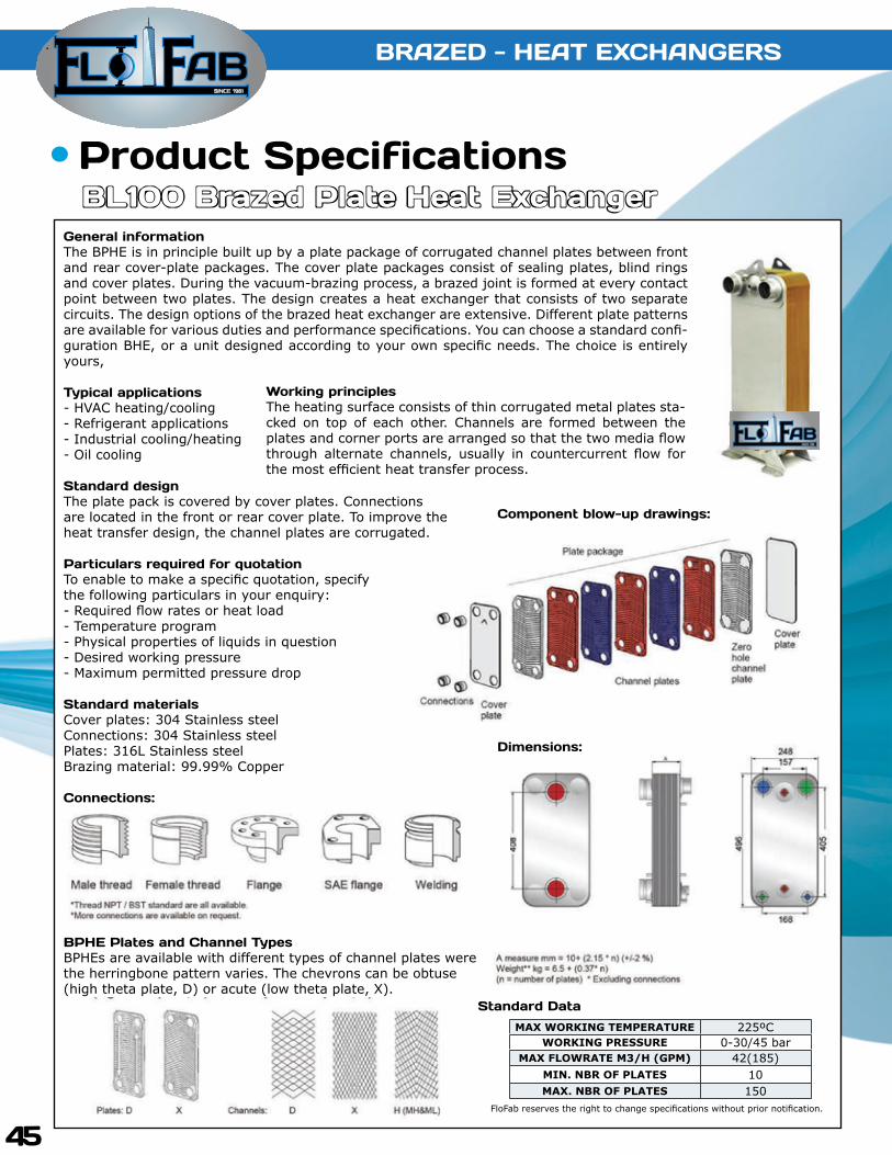
Product SpecificationsBL100 Brazed Plate Heat Exchanger
Working principlesThe heating surface consists of thin corrugated metal plates sta-cked on top of each other. Channels are formed between the plates and corner ports are arranged so that the two media flow through alternate channels, usually in countercurrent flow for the most efficient heat transfer process.
Standard DataMAX WORKING TEMPERATURE 225ºC
WORKING PRESSURE 0-30/45 barMAX FLOWRATE M3/H (GPM) 42(185)
MIN. NBR OF PLATES 10MAX. NBR OF PLATES 150
FloFab reserves the right to change specifications without prior notification.
Component blow-up drawings:
General informationThe BPHE is in principle built up by a plate package of corrugated channel plates between front and rear cover-plate packages. The cover plate packages consist of sealing plates, blind rings and cover plates. During the vacuum-brazing process, a brazed joint is formed at every contact point between two plates. The design creates a heat exchanger that consists of two separate circuits. The design options of the brazed heat exchanger are extensive. Different plate patterns are available for various duties and performance specifications. You can choose a standard confi-guration BHE, or a unit designed according to your own specific needs. The choice is entirely yours,
Typical applications- HVAC heating/cooling- Refrigerant applications- Industrial cooling/heating- Oil cooling
Standard designThe plate pack is covered by cover plates. Connections are located in the front or rear cover plate. To improve the heat transfer design, the channel plates are corrugated.
Particulars required for quotationTo enable to make a specific quotation, specify the following particulars in your enquiry:- Required flow rates or heat load- Temperature program- Physical properties of liquids in question- Desired working pressure- Maximum permitted pressure drop
Standard materialsCover plates: 304 Stainless steelConnections: 304 Stainless steelPlates: 316L Stainless steelBrazing material: 99.99% Copper
Connections:
BPHE Plates and Channel TypesBPHEs are available with different types of channel plates werethe herringbone pattern varies. The chevrons can be obtuse(high theta plate, D) or acute (low theta plate, X).
Dimensions:

SINCE 1981
BRAZED - HEAT EXCHANGERS
FloFab reserves the right to change specifications without prior notification.
46
Product SpecificationsBL120 Brazed Plate Heat Exchanger
General informationThe BPHE is in principle built up by a plate package of corrugated channel plates between front and rear cover-plate packages. The cover plate packages consist of sealing plates, blind rings and cover plates. During the vacuum-brazing process, a brazed joint is formed at every contact point between two plates. The design creates a heat exchanger that consists of two separate circuits. The design options of the brazed heat exchanger are extensive. Different plate patterns are available for various duties and performance specifications. You can choose a standard confi-guration BHE, or a unit designed according to your own specific needs. The choice is entirely yours,
Typical applications- HVAC heating/cooling- Refrigerant applications- Industrial cooling/heating- Oil cooling
Standard designThe plate pack is covered by cover plates. Connections are located in the front or rear cover plate. To improve the heat transfer design, the channel plates are corrugated.
Particulars required for quotationTo enable to make a specific quotation, specify the following particulars in your enquiry:- Required flow rates or heat load- Temperature program- Physical properties of liquids in question- Desired working pressure- Maximum permitted pressure drop
Standard materialsCover plates: 304 Stainless steelConnections: 304 Stainless steelPlates: 316L Stainless steelBrazing material: 99.99% Copper
Connections:
BPHE Plates and Channel TypesBPHEs are available with different types of channel plates werethe herringbone pattern varies. The chevrons can be obtuse(high theta plate, D) or acute (low theta plate, X).
Component blow-up drawings:
Working principlesThe heating surface consists of thin corrugated metal plates sta-cked on top of each other. Channels are formed between the plates and corner ports are arranged so that the two media flow through alternate channels, usually in countercurrent flow for the most efficient heat transfer process.
Standard DataMAX WORKING TEMPERATURE 225ºC
WORKING PRESSURE 0-30/45 barMAX FLOWRATE M3/H (GPM) 42(185)
MIN. NBR OF PLATES 4MAX. NBR OF PLATES 150
FloFab reserves the right to change specifications without prior notification.
Dimensions:
SINCE 1981
47
BRAZED - HEAT EXCHANGERS
Product SpecificationsBL190 Brazed Plate Heat Exchanger
Working principlesThe heating surface consists of thin corrugated metal plates sta-cked on top of each other. Channels are formed between the plates and corner ports are arranged so that the two media flow through alternate channels, usually in countercurrent flow for the most efficient heat transfer process.
Standard DataMAX WORKING TEMPERATURE 225ºC
WORKING PRESSURE 0-30barMAX FLOWRATE M3/H (GPM) 100(440)
MIN. NBR OF PLATES 4MAX. NBR OF PLATES 150
FloFab reserves the right to change specifications without prior notification.
Component blow-up drawings:
General informationThe BPHE is in principle built up by a plate package of corrugated channel plates between front and rear cover-plate packages. The cover plate packages consist of sealing plates, blind rings and cover plates. During the vacuum-brazing process, a brazed joint is formed at every contact point between two plates. The design creates a heat exchanger that consists of two separate circuits. The design options of the brazed heat exchanger are extensive. Different plate patterns are available for various duties and performance specifications. You can choose a standard confi-guration BHE, or a unit designed according to your own specific needs. The choice is entirely yours,
Typical applications- HVAC heating/cooling- Refrigerant applications- Industrial cooling/heating- Oil cooling
Standard designThe plate pack is covered by cover plates. Connections are located in the front or rear cover plate. To improve the heat transfer design, the channel plates are corrugated.
Particulars required for quotationTo enable to make a specific quotation, specify the following particulars in your enquiry:- Required flow rates or heat load- Temperature program- Physical properties of liquids in question- Desired working pressure- Maximum permitted pressure drop
Standard materialsCover plates: 304 Stainless steelConnections: 304 Stainless steelPlates: 316L Stainless steelBrazing material: 99.99% Copper
Connections:
BPHE Plates and Channel TypesBPHEs are available with different types of channel plates werethe herringbone pattern varies. The chevrons can be obtuse(high theta plate, D) or acute (low theta plate, X).
Dimensions:

SINCE 1981
BRAZED - HEAT EXCHANGERS
FloFab reserves the right to change specifications without prior notification.
48
Product SpecificationsBL200 Brazed Plate Heat Exchanger
General informationThe BPHE is in principle built up by a plate package of corrugated channel plates between front and rear cover-plate packages. The cover plate packages consist of sealing plates, blind rings and cover plates. During the vacuum-brazing process, a brazed joint is formed at every contact point between two plates. The design creates a heat exchanger that consists of two separate circuits. The design options of the brazed heat exchanger are extensive. Different plate patterns are available for various duties and performance specifications. You can choose a standard confi-guration BHE, or a unit designed according to your own specific needs. The choice is entirely yours,
Typical applications- HVAC heating/cooling- Refrigerant applications- Industrial cooling/heating- Oil cooling
Standard designThe plate pack is covered by cover plates. Connections are located in the front or rear cover plate. To improve the heat transfer design, the channel plates are corrugated.
Particulars required for quotationTo enable to make a specific quotation, specify the following particulars in your enquiry:- Required flow rates or heat load- Temperature program- Physical properties of liquids in question- Desired working pressure- Maximum permitted pressure drop
Standard materialsCover plates: 304 Stainless steelConnections: 304 Stainless steelPlates: 316L Stainless steelBrazing material: 99.99% Copper
Connections:
BPHE Plates and Channel TypesBPHEs are available with different types of channel plates werethe herringbone pattern varies. The chevrons can be obtuse(high theta plate, D) or acute (low theta plate, X).
Component blow-up drawings:
Working principlesThe heating surface consists of thin corrugated metal plates sta-cked on top of each other. Channels are formed between the plates and corner ports are arranged so that the two media flow through alternate channels, usually in countercurrent flow for the most efficient heat transfer process.
Standard DataMAX WORKING TEMPERATURE 225ºC
WORKING PRESSURE 0-21 barMAX FLOWRATE M3/H (GPM) 100(440)
MIN. NBR OF PLATES 10MAX. NBR OF PLATES 200
FloFab reserves the right to change specifications without prior notification.
Dimensions:

SINCE 1981
49
BRAZED - HEAT EXCHANGERS
Product SpecificationsBL210 Brazed Plate Heat Exchanger
Working principlesThe heating surface consists of thin corrugated metal plates sta-cked on top of each other. Channels are formed between the plates and corner ports are arranged so that the two media flow through alternate channels, usually in countercurrent flow for the most efficient heat transfer process.
Standard DataMAX WORKING TEMPERATURE 225ºC
WORKING PRESSURE 0-30/45barMAX FLOWRATE M3/H (GPM) 42(185)
MIN. NBR OF PLATES 100MAX. NBR OF PLATES 190
FloFab reserves the right to change specifications without prior notification.
Component blow-up drawings:
General informationThe BPHE is in principle built up by a plate package of corrugated channel plates between front and rear cover-plate packages. The cover plate packages consist of sealing plates, blind rings and cover plates. During the vacuum-brazing process, a brazed joint is formed at every contact point between two plates. The design creates a heat exchanger that consists of two separate circuits. The design options of the brazed heat exchanger are extensive. Different plate patterns are available for various duties and performance specifications. You can choose a standard confi-guration BHE, or a unit designed according to your own specific needs. The choice is entirely yours,
Typical applications- HVAC heating/cooling- Refrigerant applications- Industrial cooling/heating- Oil cooling
Standard designThe plate pack is covered by cover plates. Connections are located in the front or rear cover plate. To improve the heat transfer design, the channel plates are corrugated.
Particulars required for quotationTo enable to make a specific quotation, specify the following particulars in your enquiry:- Required flow rates or heat load- Temperature program- Physical properties of liquids in question- Desired working pressure- Maximum permitted pressure drop
Standard materialsCover plates: 304 Stainless steelConnections: 304 Stainless steelPlates: 316L Stainless steelBrazing material: 99.99% Copper
Connections:
BPHE Plates and Channel TypesBPHEs are available with different types of channel plates werethe herringbone pattern varies. The chevrons can be obtuse(high theta plate, D) or acute (low theta plate, X).
Dimensions:

SINCE 1981
BRAZED - HEAT EXCHANGERS
FloFab reserves the right to change specifications without prior notification.
50
Product SpecificationsBL600 Brazed Plate Heat Exchanger
General informationThe BPHE is in principle built up by a plate package of corrugated channel plates between front and rear cover-plate packages. The cover plate packages consist of sealing plates, blind rings and cover plates. During the vacuum-brazing process, a brazed joint is formed at every contact point between two plates. The design creates a heat exchanger that consists of two separate circuits. The design options of the brazed heat exchanger are extensive. Different plate patterns are available for various duties and performance specifications. You can choose a standard confi-guration BHE, or a unit designed according to your own specific needs. The choice is entirely yours,
Typical applications- HVAC heating/cooling- Refrigerant applications- Industrial cooling/heating- Oil cooling
Standard designThe plate pack is covered by cover plates. Connections are located in the front or rear cover plate. To improve the heat transfer design, the channel plates are corrugated.
Particulars required for quotationTo enable to make a specific quotation, specify the following particulars in your enquiry:- Required flow rates or heat load- Temperature program- Physical properties of liquids in question- Desired working pressure- Maximum permitted pressure drop
Standard materialsCover plates: 304 Stainless steelConnections: 304 Stainless steelPlates: 316L Stainless steelBrazing material: 99.99% Copper
Connections:
BPHE Plates and Channel TypesBPHEs are available with different types of channel plates werethe herringbone pattern varies. The chevrons can be obtuse(high theta plate, D) or acute (low theta plate, X).
Component blow-up drawings:
Working principlesThe heating surface consists of thin corrugated metal plates sta-cked on top of each other. Channels are formed between the plates and corner ports are arranged so that the two media flow through alternate channels, usually in countercurrent flow for the most efficient heat transfer process.
Standard DataMAX WORKING TEMPERATURE 225ºC
WORKING PRESSURE 0-20 barMAX FLOWRATE M3/H (GPM) 300(1,320)
MIN. NBR OF PLATES 10MAX. NBR OF PLATES 150
FloFab reserves the right to change specifications without prior notification.
Dimensions:

We are proud supplier for the following completed and on going projects :
Sales and Service :Quebec, CanadaTel. : (450) 621-2995Fax : (450) 621-4995
Lake WorthFlorida, USA33467-5749
Toronto, CanadaTel. : +1 (647) 544-2995
www.flofab.com SERVICE 24/7 : [email protected]
Rutgers University Apartments
604 Bartholomew RoadPiscataway, NJ 08854
Cité du Nouveau Monde64 rue St-Paul Ouest,
Montreal, QC, H2Y 1Y8
Bella Vista Ltd., 26 Torbay Road. St. John’s, NL. A2A 2G4
Le Murray1169, Rue Ottawa,
Montréal, QC H3C 1S6