heat exchangers and accessories DC220 catalogue
70
for solutions in oil heat transfer DC220 CATALOGUE heat exchangers and accessories C o o l R u n n i n g 2014
Transcript of heat exchangers and accessories DC220 catalogue

for solutions in oil heat transfer
DC220catalogue
heat exchangers and accessories
Cool Running
2014

Dynacool A 2000 CLASSICAvailable in over 30 standard model variants. Made with high performance aluminium cooling elements and heavy duty zinc seal powder coated casings for excellent appearance and durability. Stainless steel casing available on request. Available in most AC voltages, 50 & 60 Hz, hydraulic and air motor drive. Also used for air aftercooling applications. Core skirts on all models and core guards on larger models. Models with coaxially driven pump readily
Dynacool VT Vertical Discharge TowerDeveloped for very large oil cooling applications in high ambient conditions. The VT series
Versacool AC Electric DriveAvailable in 6 basic models with 22 different electric motor variants in single or three phase. 50 or 60 Hz options. Voltages from 240 through 450. The design of AC electric models delivers
Versacool DC Electric DriveAvailable in 6 Basic models with 19 different electric motor variants in 12 or 24 Volt. Proven long life water resistant fan motors in high performance or low amp/noise types. Cooling
Dynacool ST Steel Core Special ApplicationCurrently available in 4 models. ST series feature heavy duty cooling elements with steel
Ideal for low air side clogging applications or for the special requirements of underground coal
Series EKM & ECM Water Cooled Extended Surface Oil CoolersExtended surface tube bundles ensure high heat transfer capacity in small overall size and
Cu Ni tube materials now standard for stocked range ensuring good service life even if fresh
Series B General Purpose Shell & Tube Heat Exchangers General Purpose Types For all general oil, air or water cooling applications where a conventional exchanger is required.
Sea Water Types. Available for marine oil cooling or marine jacket water cooling. Special materials such as 90/10 Cu Ni & bronze are used for all surfaces in contact with sea water.
WM High Performance Marine and WI General PurposeShell & Tube Heat Exchangers WM - Extended surface tube bundle with Stainless Steel tube sheets, 90/10 Cu Ni tubes and stainless steel end bonnets. Bronze available for single pass only.
WI - Extended surface tube bundle with Steel tube sheets, 90/10 Cu Ni tubes and steel end bonnets. Both available in 1 pass, 1 pass with 90° bend or 2 pass on water side. Performance
Accessories

VersacoolStandard AC Models
Page 4-8
Dynacool “A”Standard AC Models
Page 5-9
DC70 VerticalDischarge Tower
Page 24
VT2042 VerticalDischarge Tower
Page 25
Versacool & DynacoolAir After Coolers
Page 36-38
DH Cooling ElementsNon- Aluminium
Page 40-41
B SeriesWater Cooled
Page 47
W SeriesWater CooledPage 48-50
Heat ExchangerAccessoriesPage 56-62
Product Applicationand Useful Formula
Page 63-66
Customer Selection Guide
Page 67-68
LV Replacement Fans12 & 24 VPage 19
Sendure SeriesWater Cooled
Page 51Haight PumpsPage 52-53
Pump & MotorPackages
Page 54-55
Cooling ElementsAluminium
Page 42-43
EK SeriesWater CooledPage 44-45
ECM SeriesWater Cooled
Page 46
Air Cooled Exchangerswith Co-axial Oil Pump
Page 26-28
ST ExchangersAC Electric Models
Page 30-33
DFM Non Aluminium12 & 24 V DCPage 34-35
Versacool CompactFan AC Models
Page 10-12
DC Electric Models12 & 24 V
Page 14-18
Versacool & DynacoolHydraulic Driven Models
Page 20-23
Fax Selection
FormS
contentS
3Aug2014
To ensure best quality and competitiveness product design is continuously reviewed, therefore all information published in this brochure is subject to change without notice and should not be relied upon without confirmation from our office.

54
Vcl= Standard model rangeVc = Face mount rangeVcc = compact Fan model range
BaSic moDel nUmBer = 2, 4, 5, 6, 7 or 8
coolinG element tYPen = Aluminium Hi-Flow 65mm - Operating pressure 14 Bar (VC5 model only)x = Aluminium Hi-Flow 65mm - Operating pressure 14 BarP = Aluminium Hi-Flow 65mm - Operating pressure 30 Bar (VC8 model only)
BaSic DriVe tYPea = AC electric motor.D = DC electric motor.H = Hydraulic Motor. SPeciFic Fan motor coDeSa = (DC motor only) High performance DC electric motor type.c = (AC models only) Standard Three phase 415 volt TEFC, IP55 electric motor.D = (AC models only) Standard Single phase 240 volt TEFC, IP55 electric motor.e = Hydraulic motor MGG Gresen-Tyrone gerotor type, high speed.F = Hydraulic motor small orbit Eaton J/Sam BGM/ EPMM/Danfoss OMM/etc. 16 mm shaft. end PortsQ = Hydraulic motor small orbit Eaton J/Sam BGM/ EPMM/Danfoss OMM/etc. 16 mm shaft. Side Ports (optional)G = (AC motor only) Three phase 415 volt TEFC, IP55 electric motor. Low speed, low fan noise.H = (AC motor only) Single phase 240 volt TEFC, IP55 electric motor. Low speed, low fan noise.m = Commercial Alpha Series M5 Gear Type Hydraulic Motor.nm = No motor (electric motor mounting provided)x = Special Hydraulic Motor Mount For Customer Supplied Motor.
Dc VoltaGe or ac HertZ electric motor coDeS1 = (DC motor only) 12 Volt power supply.2 = (DC motor only) 24 Volt power supply. 5 = (AC motor only) 50 Hertz AC power supply.6 = (AC motor only) 60 Hertz AC power supply. Consult sales with voltage before ordering.Omitted = No Motor Unit
SPecial DetailS or FiniSH0= Standard Model. Other numbers indicate special features.00 = No Motor unit.F = Aluminium Core Element with extra corrosion resistant finishAccessories are not indicated on model identification. Order separately.
air cooled exchangers With aluminium cooling elementsVERSACOOL SERiES COOLER
• AC electric models deliver more air flow resulting in greater perform-ance while using a smaller diameter lower noise fan. Cylindrical air jet discharge pattern eliminates recycling of heated air through matrix.
• Choice of Hi-Flow low pressure drop cooling elements on all larger models.
• Highest performance in the smallest package allows use in confined spaces, universal top and bottom mount makes vertical, horizontal or inverted mounting easy. Accessory mounting feet (page 58) are available.
• Ease of assembly and commonality of components makes for a large array of models. 73 models are currently available from stock.
Mounting feet and thermostat options page 56-58.
Vcl 4 x a c 5 0VerSacool moDel coDeS
air
coo
leD
ac D
c HY
D Dr
iVe

54
BaSic moDel nUmBer = 31, 32, 33, 35 & 70
coolinG element tYPeS = Hi-Flow 90mm - Operating pressure 14 Bar (Ports on opposite side)G = Hi-Flow 70mm - Operating pressure 14 Bar (Ports on same side)l = Hi-Flow 95mm - Operating pressure 14 Bar (Ports on same side)U = Hi-Flow 95mm - Operating pressure 14 Bar (Ports on opposite side)V = Hi-Flow 95mm - Operating pressure 20 Bar (Ports on same side)Y = Hi-Flow 65mm - Operating pressure 14 Bar (Ports on opposite side)
Port orientationH = HorizontalV = Vertical
Fan Diameter (mm)5 = Ø5006 = Ø6308 = Ø8009 = Ø89210 = Ø1000
BaSic DriVe tYPeac = 3 Phase electric motoraD = 1 Phase electric motorDa = DC MotorHF = Hydraulic orbit motor with end portsHQ = Hydraulic orbit motor with side ports (optional)HV = Hydraulic vane motorHx = No motor (hydraulic motor mounting provided. Customer to specify motor details)nm = No motor (electric motor mounting provided)Ga = Air motor
motor/Fan SPeeD2 = 2 Pole Nom. 2800rpm at 50 Hz4 = 4 Pole Nom. 1450rpm at 50 Hz6 = 6 Pole Nom. 950rpm at 50 Hz8 = 8 Pole Nom. 750rpm at 50 Hz
SPecial DetailS or FiniSH00 or none = 415V 50HzV = 3.5 Bar bypass valveF = Extra corrosion resistant finishBB = Coaxial BB Pump fitted to 3 Phase electric fan motor (see page 26)HP = Coaxial Haight Pump fitted to 3 Phase electric fan motorPP = Separate pump/ motor package fitted to cooler.
# not all combinations are available or possible
air cooled exchangers With aluminium cooling elementsDYNACOOL SERiES A 2000 CLASSiC
• Australian designed and manufactured product with reputation for quality, reliability and technical excellence.
• With over 30 years experience, constant development and testing has produced the Series A 2000 the most compact and lowest noise oil cooler in its performance range.
• The largest air cooled heat exchanger inventory in the southern hemi-sphere means that you can demand and receive the fastest delivery of new units and service parts exactly when you need them.
D c 32 Y H 8 ac 6 00 #DYnacool moDel coDeS
air coo
leDac Dc HYD DriVe

76
air cooled exchangers With aluminium cooling elementsAC ELECTRiC HEAT EXCHANGERS
TECHNiCAL SPECiFiCATiONS - AC ELECTRiC MODELS
Electric Motor Specifications• Dynacool A 2000 Series. 50 Hz 3 phase
asynchronous to iEC 34-1, B3 mount iP55, Insulation- Class F. Temperature rise- Class B
• Versacool. 50Hz asynchronous to IEC 34-1, B3 mount IP55, Insulation- Class F. Temperature rise- Class B
• 60 Hz available with reduction of fan blade angles.
* Noise levels listed are raw A weighted pressure representing worst case. Refer noise level statement page 65
General construction• Cooling Elements. Aluminium furnace brazed. Ref. to
pages 4 and 5 for element types.
• Casing and Structure. Steel (zinc seal) polyester powder coated. Stainless steel to special order.
• Steel core guards on Dynacool models.
• Coated steel fan guards on all models.
• Fans. Polypropylene GF or Polyamide GF. Antistatic fans available on request.
• Fastenings. Zinc plated. Stainless steel to special order.
MODEL/ Noise level * Fan Ø Volts Phase kW Size Poles Weight Part Number dB(A) at 1m (mm) (kg) VC2XAC50 82 243 415 3 0.25 63 2 12 VC2XAD50 82 243 240 1 0.24 63 2 12 VC2XAG50 65 243 415 3 0.18 63 4 12 VC2XAH50 65 243 240 1 0.15 63 4 12 VCL4XAC50 84 305 415 3 0.37 71 2 20 VCL4XAD50 84 305 240 1 0.37 71 2 20 VCL4XAG50 68 305 415 3 0.25 71 4 20 VCL4XAH50 68 305 240 1 0.187 71 4 20 VCL5NAC50 87 354 415 3 0.75 80 2 30 VCL5NAD50 87 354 240 1 0.75 80 2 30 VCL5NAG50 71 354 415 3 0.37 71 4 26 VCL5NAH50 71 354 240 1 0.37 71 4 26 VCL6XAC50 78 450 415 3 0.55 80 4 37 VCL6XAD50 78 450 240 1 0.55 80 4 37 VCL6XAG50 68 450 415 3 0.55 80 6 39 VCL7XAC50 78 450 415 3 0.55 80 4 39 VCL7XAD50 78 450 240 1 0.55 80 4 39 VCL7XAG50 68 450 415 3 0.55 80 6 41 VCL8PAC50 90 354 415 3 0.75 80 2 69 VCL8PAD50 90 354 240 1 0.75 80 2 69 VCL8PAG50 74 354 415 3 0.37 71 4 67 VCL8PAH50 74 354 240 1 0.37 71 4 67 DC31YH5AC400 84 500 415 3 0.75 80 4 68 DC31YH6AC600 78 630 415 3 1.1 90 6 83 DC32YH6AC400 89 630 415 3 1.5 90L 4 90 DC32YH8AC600 84 800 415 3 2.2 112 6 91 DC32YH8AC800 79 800 415 3 1.1 100 8 91 DC32SH6AC400 89 630 415 3 1.5 90L 4 90 DC32SH8AC600 88 800 415 3 2.2 112 6 99 DC32SH8AC800 79 800 415 3 1.1 100 8 99 DC33VH6AC400 89 630 415 3 1.5 90L 4 180 DC33VH8AC400 96 800 415 3 3.0 100 4 180 DC33VH8AC600 87 800 415 3 2.2 112 6 180 DC35GH8AC400 96 800 415 3 3.0 100 4 195 DC35GH8AC600 87 800 415 3 2.2 112 6 195 DC35GH8AC800 79 800 415 3 1.1 100 8 195 DC35GH9AC600 92 892 415 3 2.2 112 6 195 DC35GH9AC800 85 892 415 3 1.1 100 8 195 DC35LH9AC600 92 892 415 3 2.2 112 6 210 DC35LH9AC800 85 892 415 3 1.1 100 8 210 DC70GH10AC600 85 1000 415 3 5.5 132M 6 380
air cooleD SPecial aPPlication
air
coo
leD
ac D
c HY
D Dr
iVe

oil cooler SiZinGStep 1. Calculate ETD = TOil - TAirTOil= Temp °C of oil entering the cooler (usually the same as max. allowable oil temp.) TAir= Expected Ambient Air Temp°C.Step 2. Calculate kW/°C ETD = kW kW = Heat Load. ETDStep 3. Enter Cooler Performance Tables and select a cooler which meets or exceeds the required performance at the required oil flow rate.Step 4. Check pressure drop of the oil cooler selected in step 3. If the average oil viscosity is not 30 cSt apply a correction for the expected viscosity.Computer model selection program available.
76
0.05
0.1
0.2
0.3
kW/°C
0.4
0.5
1.0
2.0
3.0
4.0
5.0
9.0
Oil Flow l/min5 10 20 100 200 500
5 10 20 100 200 500
50
50
1000
1000
VC2XAC50
VCL4XAG50
VCL4XAC50
VCL5NAC50/VCL6XAG50
VCL6XAC50VCL7XAG50
DC31YH6AC6VCL7XAC50
DC31YH5AC4/VC8PAC50
VCL5NAG50
DC32YH8AC8
DC32YH6AC4DC32YH8AC6
DC70GH10AC6
DC35GH9AC8DC35GH8AC6
DC35GH9AC6DC35GH8AC4
DC35LH9AC6
DC32SH8AC6DC32SH6AC4
DC32SH8AC8
DC35LH9AC8
DC35GH8AC8
VCL8PAG50
DC33VH8AC4DC33VH6AC4/DC33VH8AC6
1
2
345
0.1
0.5DP
Bar
100 200 500502010Oil Flow l/min
VC2X
VCL4
X
VCL5
N/6X
VCL7
X
1
2
345
0.1
0.5DP
Bar
100 200 500 100050Oil Flow l/min
DC70G
DC35G
DC32Y
DC31Y
DC33V/D
C35L
DC32S
VCL8
P
20 40 60 80 100 120Oil Viscosity cSt
PCo
rrec
tion
Fac
tor
1
2
3
NOTE: 240 Volt Single Phase VC Models AD and AH.Use AC curve to find performance of ADUse AG curve to find performance of AH
air cooled exchangers With aluminium cooling elementsPERFORMANCE - STANDARD & HiFLOW AC ELECTRiC MODELS
air cooleD SPecial aPPlication
air
coo
leD
ac D
c HY
D Dr
iVe
4-Off Ø10 x 16 LongMounting SlotsTop & Bottom
AIRFLOW
E
A1
A2
BH 105 G*14 77 14
D1
D2
C
F1
F2
J
"A""B"
"D"
"C"
"B"
"A"
"C"
240*308
248318
280
7
6077
10535
FAN
AIR
Slots 16 x 10 4 Places
Bottom And Top
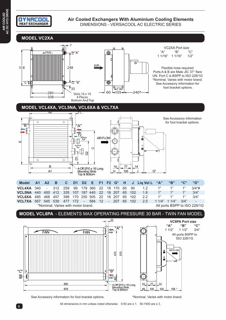
VC2XA Port size “A” “B” “C” 1 1/16” 1 1/16” 1/2”
model a1 a2 B c D1 D2 e F1 F2 G* H J liq Vol l “a” “B” “c” “D” Vcl4xa 340 - 312 259 99 179 360 22 18 170 65 90 1.2 1” 1” 1” 3/4”# Vcl5na 440 400 412 335 107 187 440 22 18 207 65 102 1.8 1” 1” 1” 3/4” Vcl6xa 485 468 457 398 170 250 505 22 18 207 65 102 2.2 1” 1” 1” 3/4” Vcl7xa 567 545 539 477 172 - 584 12 - 207 65 102 2.5 1 1/4” 1 1/4” 3/4” - *Nominal, Varies with motor brand. All ports BSPP to ISO 228/1G
air cooled exchangers With aluminium cooling elementsDiMENSiONS - VERSACOOL AC ELECTRiC SERiES
moDel Vc2xa
moDel Vcl8Pa - ELEMENTS MAX OPERATiNG PRESSURE 30 BAR - TWiN FAN MODEL
Flexible hose requiredPorts A & B are Male JIC 37° flare UN. Port C is BSPP to ISO 228/1G*Nominal, Varies with motor brand.
See Accessory information for foot bracket options.
See Accessory information for foot bracket options. *Nominal, Varies with motor brand.
All dimensions in mm unless noted otherwise 0-50 are ± 1. 50-1500 are ± 3.98
4-Off Ø10 x 16 LongMounting SlotsTop & Bottom
AIR FLOW
65 105 102 158 *
14 77 14850
878
4847
4
570
22
"A"
"B""C"
FAN FAN
See Accessory information for foot bracket options.
All ports BSPP to iSO 228/1G
moDel Vcl4xa, Vcl5na, Vcl6xa & Vcl7xa
Vc8Pa Port size “a” “B” “c” 1 1/2” 1 1/2” 3/4”
air coo
leDac Dc HYD DriVeai
r co
ole
Dac
Dc
HYD
DriV
e

(4) Ø14 HolesFor Mounting
AIRFLOW
G=60.0L=72.5
G=690*L=710*
583119.
511
25
1289
1192
1140
1196
"A"
"B""C"
5233028
75
77
Lifting LugsWLL 125kg Each
AIR FLOW
G
C
75DE
H
BA (2) Lifting Eye Bolts Ø14
WLL 250 kG Each
K 200 140400
(6) Ø14 HOLESFOR MOUNTING
35
"B""A"
"C"
F
98
(4) Ø14 HolesFor Mounting
AIR FLOW
706*
583
120
1030
1195
1061
1066
"A"
"B"
"C"
75
523
72
101028 30
77
Lifting LugWLL 125kg each
model a B c D e F* G H K “a” “B” “c” 31Y 674 694 618 255 406 515* 277 762 53 1 1/4” 1 1/4” 1 1/4” 32S 840 882 784 177 663 590* 302 940 78 2” 2” 3/4” 32Y 840 847 784 255 585 565* 277 940 53 1 1/4” 1 1/4” 1 1/4”
moDel Dc33
moDel Dc31 & Dc32
moDel Dc35 l & G
All ports BSPP to iSO 228/1G*Nominal, Varies with motor brand.
All dimensions in mm unless noted otherwise 0-50 are ± 1. 50-1500 are ± 3.
air cooled exchangers With aluminium cooling elementsDiMENSiONS - DYNACOOL SERiES A 2000 CLASSiC AC ELECTRiC
All ports BSPP to iSO 228/1G*Nominal, Varies with motor brand.
All ports BSPP to iSO 228/1G*Nominal, Varies with motor brand.
Dc33 Port size “a” “B” “c” 2” 2” 3/4”
Dc35 Port size “a” “B” “c” 2” 2” 3/4”
air coo
leDac Dc HYD DriVeai
r co
ole
Dac
Dc
HYD
DriV
e

air cooled exchangers With aluminium cooling elementsVERSACOOL COMPACT AC FAN HEAT EXCHANGERS
MODEL/ Fan Ø Volts Phase Watts Poles Weight Noise Level* Part Number (mm) (kg) dB(A) @ 1m VCC4XAG50 300 415 3 90 4 13 70 VCC4XAH50 300 240 1 90 4 13 70 VCC5NAG50 350 415 3 140 4 18 72 VCC5NAH50 350 240 1 140 4 18 72 VCC6XAC50 450 415 3 150 4 24 75 VCC6XAD50 450 240 1 150 4 24 75 VCC7XAC50 450 415 3 150 4 28 75 VCC7XAD50 450 240 1 150 4 28 75 VCC8PAG50 2 x 350 415 3 2 x 140 4 45 74 VCC8PAH50 2 x 350 240 1 2 x 140 4 45 74
Compact depth allows use in situations such as power packs & mobile equip-ment where space is limited.Uses the same cooling elements as our standard range VCL modelsUniversal top and bottom mount makes vertical, horizontal or inverted mounting easy. Accessory mounting feet (page 58) are available.Versacool Compact Fan models in single phase 240V or 3 phase 415V 50Hz IP54.
General constructionCooling Elements. Aluminium furnace brazed. Casing and Structure. Steel (zinc seal) polyester powder coated. Compact fan & integral motor with coated steel fan guards on all models. Fastenings. Zinc plated.
•
•
•
•
•
•
•
•
Versacool Compact Range
1110
air coo
leDac Dc HYD DriVeai
r co
ole
Dac
Dc
HYD
DriV
e
* Noise levels listed are raw A weighted pressure representing worst case. Refer noise level statement page 65

1
2345
0.1
0.5DP
Bar
100 200 500502010Oil Flow l/min
VCC4
X
VCC7
XVCC8P
VCC5
N/VCC
6X
20 40 60 80 100 120Oil Viscosity cSt
PCo
rrec
tion
Fac
tor
1
2
3
oil cooler SiZinGStep 1. Calculate ETD = TOil - TAirTOil= Temp °C of oil entering the cooler (usually the same as max. allowable oil temp.) TAir= Expected Ambient Air Temp°C.Step 2. Calculate kW/°C ETD = kW kW = Heat Load. ETDStep 3. Enter Cooler Performance Tables and select a cooler which meets or exceeds the required performance at the required oil flow rate.Step 4. Check pressure drop of the oil cooler selected in step 3. If the average oil viscosity is not 30 cSt apply a correction for the expected viscosity.Computer model selection program available.
air cooled exchangers With aluminium cooling elementsPERFORMANCE-VERSACOOL COMPACT AC FAN HEAT EXCHANGERS
0.05
0.1
0.2
0.3
kW/°
C
0.4
0.5
1.0
Oil Flow l/min5 10 20 100 200
5 10 20 100 200
50
50
VCC4XAG50/ VCC4XAH50
VCC6XAC50/ VCC6XAD50
VCC5NAG50/ VCC5NAH50
VCC7XAC50/ VCC7XAD50
VCC8PAG50/ VCC8PAH50
1110
air coo
leDac Dc HYD DriVeai
r co
ole
Dac
Dc
HYD
DriV
e

4-Off Ø10 x 16 LongMounting SlotsTop & Bottom
AIRFLOW
65 105 82
14 77 14850
878
4847
4
570
22
"A"
"B""C"
FAN FAN
4-OFF Ø10 x 16 LONGMOUNTING SLOTSTOP & BOTTOM
AIRFLOW
E
A1
D1
D2
C
65 105 G
77
A2
B
F1
"A" "B"
"D"
"C"
model a1 a2 B c D1 D2 e F1 G liq Vol l “a” “B” “c” “D” Vcc4xa 340 330 312 259 99 179 360 22 80 1.2 1” 1” 1” 3/4”# Vcc5na 440 400 412 335 107 187 440 22 84 1.8 1” 1” 1” 3/4” Vcc6xa 485 468 457 398 170 250 505 22 101 2.2 1” 1” 1” 3/4” Vcc7xa 567 545 539 477 172 - 584 22 101 2.5 1 1/4” 1 1/4” 3/4” - All ports BSPP to iSO 228/1G
moDel Vcc8Pa - ELEMENTS MAX OPERATiNG PRESSURE 30 BAR - TWiN FAN MODEL
See Accessory information for foot bracket options.
All dimensions in mm unless noted otherwise 0-50 are ± 1. 50-1500 are ± 3.
See Accessory information for foot bracket options.
All ports BSPP to iSO 228/1G
moDel Vcc4xa, Vcc5na, Vcc6xa & Vcc7xa
air cooled exchangers With aluminium cooling elementsDiMENSiONS-VERSACOOL COMPACT AC FAN HEAT EXCHANGERS
1312
Vc8Pa Port size “a” “B” “c” 1 1/2” 1 1/2” 3/4”
air
coo
leD
ac D
c HY
D Dr
iVe

THiS PAGE LEFT BLANK
1312
air
coo
leD
ac D
c HY
D Dr
iVe

air cooled exchangers With aluminium cooling elementsDC ELECTRiC HEAT EXCHANGERS
Electric Motor Specifications• Versacool DA Type. High performance, long life,
motor enclosure IP68. Temp range -30°C to +80°C.
General construction• Cooling Elements. Aluminium furnace brazed.
• Casing. Steel (zinc seal) Polyester powder coated.
• Fans. Polypropylene.
• Fastenings. Zinc plated
TECHNiCAL SPECiFiCATiONS - DC ELECTRiC MODELS
• Total of 20 stock models including 12 and 24 volts. DA models are high performance with long life SPAL fans.
• Our Versacool range has the highest performance in the smallest package and allows use in confined spaces. The universal top and bottom mount makes vertical, horizontal or inverted mount-ing easy. Accessory mounting feet are available. See page 58 for details.
• Can be fitted with optional electric DC thermoswitch kits which control the start of the fan when the oil reaches a predetermined temperature. Kits are available with temperature settings of 55°C and 65°C. Other temperature ranges are available upon request.See pages 56 and 57 for details.
* Noise levels listed are raw A weighted pressure representing worst case. Refer noise level statement page ??General Arrangement Drawings of models not shown are available upon request from our Sales Office.
DA High Performance
Mounting feet and thermostat options page ??-??.
1514
moDel/ noise level * Fan Ø Volts amps Weight Part number dB(a) at 1m (mm) kg VC2XDA10 80 254 12 9 8 VC2XDA20 80 254 24 7.2 8 VC4XDA10 80 305 12 14.5 11.5 VC4XDA20 80 305 24 9.3 11.5 VC5NDA10 80 305 12 14.5 14 VC5NDA20 80 305 24 9.3 14 VC6XDA10 80 305 12 14.5 15.8 VC6XDA20 80 305 24 9.3 15.8 VC7XDA10 83 2 x 305 12 29 25 VC7XDA20 83 2 x 305 24 18.6 25 VC8PDA10 83 2 x 305 12 29 40 VC8PDA20 83 2 x 305 24 18.6 40 DC31YH2DA10 85 4 x 254 12 36 56 DC31YH2DA20 85 4 x 254 24 29 56 DC32YH3DA20 90 4 x 305 24 33 90 DC32SH3DA20 90 4 x 305 24 33 95 TM20JDA10 76 190 12 7.7 5 TM20JDA20 76 190 24 3.0 5 TM40JDA10 80 305 12 14.5 8 TM40JDA20 80 305 24 9.3 8
air coo
leDac Dc HYD DriVeai
r co
ole
Dac
Dc
HYD
DriV
e

1514
0.05
0.1
0.2
0.3
kW/°C
0.4
0.5
Oil Flow l/min
5 10 20 100 200 300 400 50050
0.6
0.7
0.8
0.91.0
0.04
0.03
0.02
VC2XDA
VC4XDA
VC6XDA
VC5NDA
TM40JDA
TM20JDA
2.0
3.0
VC8PDA
DC32YH3DA20
DC32SH3DA20
VC7XDA
DC31YH2DA
air cooled exchangers With aluminium cooling elementsPERFORMANCE - DC ELECTRiC MODELS
1
2
345
0.1
0.5DP
Bar
100 200 500502010Oil Flow l/min
VC2X
/TM
20VC
4X/T
M40 VC
5N/6
XVC
L7X
1
2
345
0.1
0.5DP
Bar
100 200 500 100050Oil Flow l/min
DC32Y
DC31Y
DC32S
VC8P
20 40 60 80 100 120Oil Viscosity cSt
PCo
rrec
tion
Fac
tor
1
2
3
oil cooler SiZinGStep 1. Calculate ETD = TOil - TAirTOil= Temp °C of oil entering the cooler (usually the same as max. allowable oil temp.) TAir= Expected Ambient Air Temp°C.Step 2. Calculate kW/°C ETD = kW kW = Heat Load. ETDStep 3. Enter Cooler Performance Tables and select a cooler which meets or exceeds the required performance at the required oil flow rate.Step 4. Check pressure drop of the oil cooler selected in step 3. If the average oil viscosity is not 30 cSt apply a correction for the expected viscosity.Computer model selection program available.
air coo
leDac Dc HYD DriVeai
r co
ole
Dac
Dc
HYD
DriV
e

Slots 16 Along 10 Across4 Places Bottom And Top
"B"
"A"
"C"
69
308
248318
280
7
6077
10535
FAN
AIR
Slots 16 Along 10 Across4 Places Bottom And Top
"B" "A"
"C" CE
D1
F1
A2
BA1
77105 GH
"D"
D2
FAN
AIR
All dimensions in mm unless noted otherwise 0-50 are ± 1. 50-1500 are ± 3. 1716
air cooled exchangers With aluminium cooling elementsDiMENSiONS - VERSACOOL DC ELECTRiC MODELS
moDel Vc4xD, Vc5nD & Vc6xD
moDel Vc2xD
model a1 a2 B c D1 D2 e F1 F2 G* H liq Vol l “a” “B” “c” “D” Vc4xDB 340 - 312 259 99 179 360 22 18 54 65 1.2 1” 1” 1” 3/4” Vc4xDa 340 - 312 259 99 179 360 22 18 69 65 1.2 1” 1” 1” 3/4” Vc5nDa 440 400 412 335 107 187 440 22 18 69 65 1.8 1” 1” 1” 3/4” Vc6xDa 412 463 384 379 150 230 464 22 18 69 65 2.2 1” 1” 1” 3/4” All ports BSPP to iSO 228/1G
Flexible hose requiredPorts A & B are Male JIC 37° flare UN.
Port C is BSPP to iSO 228/1GSee Accessory information for
foot bracket options.
VC2XD Port size “a” “B” “c” 1 1/16” 1 1/16” 1/2”
See Accessory information for foot bracket options.
567Mounting Slots - 4 Off0 10 X 16 Long
14539
176.
248
1
14
584
591
7714 1465 105 78
"A""B"
"C"
VC7XDA Port size “a” “B” “c” 1 1/4” 1 1/4” 3/4”
All ports BSPP to iSO 228/1GSee Accessory information for
foot bracket options.
moDel Vc7xDa
air coo
leDac Dc HYD DriVeai
r co
ole
Dac
Dc
HYD
DriV
e

1716
air cooled exchangers With aluminium cooling elementsDiMENSiONS - DYNACOOL DC ELECTRiC MODELS
moDel Dc32
model a B c D e F G H K “a” “B” “c” 31Y 674 694 618 255 406 379 277 762 53 1 1/4” 1 1/4” 1 1/4” 32S 840 860 784 177 663 379 302 940 78 2” 2” 3/4” 32Y 840 860 784 255 585 404 277 940 53 1 1/4” 1 1/4” 1 1/4” All ports BSPP to iSO 228/1G
All dimensions in mm unless noted otherwise 0-50 are ± 1. 50-1500 are ± 3.
VC8PDA Port size “a” “B” “c” 1 1/2” 1 1/2” 3/4”
All ports BSPP to iSO 228/1GSee Accessory information for
foot bracket options.
moDel Vc8PDa - ELEMENTS MAX OPERATiNG PRESSURE 30 BAR - TWiN FAN MODEL
AIR
850878
47.5
"A"
"B""C"
7710565 69
24 17
FAN FAN
475 570
Mounting Slots - 4 Off0 10 X 16 Long
AIR FLOW
"C"
"B""A"
(6) Ø14 HOLESFOR MOUNTING
75
G
DE
A
B
H
F
C K 200 140
400
(2) Lifting Eye Bolts Ø14WLL 250kg Each
See Accessory information pages 58 & 59 for Thermoswitch options.
air coo
leDac Dc HYD DriVeai
r co
ole
Dac
Dc
HYD
DriV
e

1918
air cooled exchangers With aluminium cooling elementsTM - TRANSiT MiXER COOLERS
322
240
"A"
"B"
30
87
330
203
AIR
167"C"
6595
296
4 MountingHoles Ø12.7
16
311286 60
134
"B"
"A"
"C"
AIR 4 MountingHoles Ø8
FAN
FAN
145288 248
Part number Motor voltage Amps Weight(kg) tm20JDa10 12v 8.1 5 Port Details - A and B are Male JIC 37° flare UN type 1 1/16” 12TPI tm20JDa20 24v 3.0 5 C is 1/2” BSPP to ISO 228/1G. Flexible hose required.
moDel tm40JDa
moDel tm20JDa
tm40 cooleraPPlication. Suitable for use in mobile equipment to cool hydraulic oil. Fan driven using 12 or 24 volt DC power supply. Optional thermoswitch available for TM models for extended fan motor life refer to page 56 for details.
SPeciFicationS.Maximum Operating Pressure ........14 BarMaximum Operating Temperature ..100°C
materialS oF conStrUction.Cooling element........... AluminiumCase (TM20 only) ........ Steel, powder coated whiteFan/Cowl ..................... Plastic, blackMotor ........................... Steel Case, weatherproofed
Part number Motor voltage Amps Weight(kg) tm40JDa10 12v 16.5 8 Port Details - A and B are Male JIC 37° flare UN type 1 1/16” 12TPI tm40JDa20 24v 9.3 8 C is 1/2” BSPP to ISO 228/1G
All dimensions in mm unless noted otherwise 0-50 are ± 1. 50-1500 are ± 3.This model also available with 1” BSPP ports. p/n TM40XDA
air coo
leDac Dc HYD DriVeai
r co
ole
Dac
Dc
HYD
DriV
e
Core P/N 18/06011
Core P/N18/06183

1918
GENERAL DESCRIPTION. These Axial flow low voltage fans are a low profile high performance fan that can be used for cooling or ventilation on most off road applications.
CONSTRUCTION. The blades and shrouds are made of glass filled nylon. Straight mount feet are also glass filled nylon with M5 threaded insert. Face mount feet are also available.
PERFORMANCE RANGE. Flow at 0.87 cubic metres per second.
ELECTRIC MOTOR SPECIFICATIONS. The motors used are a high perform-ance water/dust resistant type. The models are available for either 12V or 24V DC supply.
H
Z
X
W
D
Y
M5 Straight Feet StandardFace Mount Feet Also Available.
GENERAL DESCRIPTION. These Axial flow low voltage fans are long life high performance fans that can be used for cooling or ventilation on most off road applications. A suitable fuse should be provided to protect the motor.
CONSTRUCTION. The blades and shrouds are made of glass filled nylon.
PERFORMANCE RANGE. This range of low voltage fans has improved static pressure performance. Three sizes are available offering flows ranging from 0.21 to 0.8 cubic metres per second.
ELECTRIC MOTOR SPECIFICATIONS. The motors used are a high perform-ance long life water/dust resistant type. The models are available for either 12V or 24V DC supply.
PERFORMANCE. DIMENSIONS. PART SERIES VOLTS FREE CURRENT W H D X Y Z NUMBER AiR m3/s (Amps) (mm) (mm) (mm) (mm) (mm) (mm) 67/66991 356 (14”) 12 0.87 12.5 357 100 372 377 180 16 67/66992 356 (14”) 24 0.87 6.3 357 100 372 377 180 16
PERFORMANCE. PART SERiES VOLTS FREE AiR CURRENT NUMBER m3/s (Amps) 039.8.05977 190 (7.5”) 24 0.21 2.5 039.8.05976 190 (7.5”) 12 0.24 7.7 039.8.04712 255 (10”) 12 0.52 10.5 039.8.04711 255 (10”) 24 0.54 6.5 039.8.04709 305 (12”) 24 0.8 8.5 039.8.04710 305 (12”) 12 0.76 14.5
SerieS 19021
020252
4 holes ¯6on 213.5 PCD
96 286
277
269
145
4 HOLES Ø10
SerieS 255
loW VoltaGe rePlacement FanS
loW ProFile axial FanS
HiGH PerFormance axial FloW FanS
air coo
leDac Dc HYD DriVeai
r co
ole
Dac
Dc
HYD
DriV
e
SerieS 30594 331
4 Slots Ø6 x 10 longon 340 P.C.D.
4 Holes Ø6on 337 P.C.D.

TECHNiCAL SPECiFiCATiONS - COOLERS WiTH HYDRAULiC MOTORS
air cooled exchangers With aluminium cooling elementsHYDRAULiC DRiVE COOLERS
Hydraulic motor fan drives are available on most Versacool and Dynacool heat exchangers
Compact face mount system
Hydraulic motor options include either a 8cc or a 12cc mini orbit motor.
HX coolers available for fitting of customer supplied hydraulic motors. Consult our sales office.
Overhung load adaptors can be supplied and fitted for plug-in on HX hydraulic motor types.
For mounting either face up or face down, please consult with our sales office.
•
•
•
•
•
•
Model Motor type Motor size Req’d Motor Oil flow Motor power Weight(3) noise level* cc/rev speed rpm req’d l/min kW (kg) (dBa) at 1m Vcl4xHF12/19 Orbit (2) 8.2/12.9 1440 12/19 0.25 16 68 Vcl5nHF12/19 Orbit (2) 8.2/12.9 1440 12/19 0.37 20 71 Vcl6xHF12/19 Orbit (2) 8.2/12.9 1440 12/19 0.55 27 78 Vcl7xHF12/19 Orbit (2) 8.2/12.9 1440 12/19 0.55 29 78 Vcl8PHF412/19 2 x Orbit (2) 8.2/12.9 1440 12/19 2 x 0.37 47 74 Dc31YH5HF412/19 Orbit (2) 8.2/12.9 1440 12/19 0.75 55 84 Dc31YH6HF612/20 Orbit (2) 12.9/20 920 12/20 0.55 56 78 Dc32YH6HF412/19 Orbit (2) 8.2/12.9 1440 12/19 1.5 89 Dc32YH8Hx6/8(1) Cust. supply - 920/710 - 2.2/1.1 84 / 79 Dc32SH8Hx6/8(1) Cust. supply - 920/710 - 2.2/1.1 88 / 79 Dc33VH6HF412/19 Orbit (2) 8.2/12.9 1440 12/19 1.5 89 Dc33VH8Hx400(1) Cust. supply - 1440 - 3.0 96 Dc33VH8Hx600(1) Cust. supply - 920 - 2.2 87 Dc35GH8Hx6/8(1) Cust. supply - 920/710 - 2.2/1.1 87 / 79 Dc35GH9Hx600(1) Cust. supply - 920 - 2.2 92 Dc35lH9Hx600(1) Cust. supply - 920 - 2.2 92 (1) Customer to specify motor details when ordering. (2) For Heat Exchanger models “HF” & “HQ” fitted with orbit motors. Ports on orbit motors are 3/8” BSPP.
“HF” models are fitted with orbit motors with end ports, “HQ” models are fitted with orbit motors with side ports.(Optional) In above table, replace code “HF” with code “HQ” when selecting side port option.
(3) Weight is estimated. Note: “HX” models are weight without customer supplied motor. Performance curves and noise levels are based on required motor speed. * Noise levels listed are raw A weighted pressure representing worst case. Refer noise level statement page 65
MiNi ORBiT MOTOR
2120
Mounting feet and thermostat options page 56-58.
air coo
leDac Dc HYD DriVeai
r co
ole
Dac
Dc
HYD
DriV
e

air cooled exchangers With aluminium cooling elementsHYDRAULiC DRiVE COOLERS
2120
1
2
345
0.1
0.5DP
Bar
100 200 500 100050
Oil Flow l/min
DC70
Y
DC35
Y
DC32
Y
DC31
Y
DC33
V/DC
35U
DC32
S
1
2
345
0.1
0.5DP
Bar
100 200 500502010Oil Flow l/min
VCL4
X
VCL5
N/6X
VCL7
XVC
L8P
0.05
0.1
0.2
0.3
kW/°
C
0.4
0.5
1.0
2.0
3.0
4.0
5.0
9.0
Oil Flow l/min5 10 20 100 200 500
5 10 20 100 200 500
50
50
1000
1000
DC31YH5HF4
DC35GH9HX6
DC35GH9HX8DC35GH8HX6
DC32YH8HX8
DC32YH8HX6DC32YH6HF4
DC31YH6HF6
VCL6XHF
VCL7XHF
VCL4XHF
DC35LH9HX6
DC32SH8HX8
DC32SH8HX6
VCL5NHF
DC33VH8AC4DC33VH6AC4/DC33VH8AC6
VCL8PHF4
20 40 60 80 100 120Oil Viscosity cSt
PCo
rrec
tion
Fac
tor
1
2
3
oil cooler SiZinGStep 1. Calculate ETD = TOil - TAirTOil= Temp °C of oil entering the cooler (usually the same as max. allowable oil temp.) TAir= Expected Ambient Air Temp°C.Step 2. Calculate kW/°C ETD = kW kW = Heat Load. ETDStep 3. Enter Cooler Performance Tables and select a cooler which meets or exceeds the required performance at the required oil flow rate.Step 4. Check pressure drop of the oil cooler selected in step 3. If the average oil viscosity is not 30 cSt apply a correction for the expected viscosity.Computer model selection program available.
air coo
leDac Dc HYD DriVeai
r co
ole
Dac
Dc
HYD
DriV
e

AIR FLOWE
B
A1
FA2
D1 D
2
C
65 105 102 G *
77
"A" "B"
"C"
"D"
FAN
4-Off 0 10 x 16 LongMounting SlotsTop & Bottom
4-Off Ø10 x 16 LongMounting S lotsTop & Bottom
AIR FLOW
65 105 101.5 59
14 77 14850
878
4847
4
570
22
"A"
"B""C"
FAN FAN
22
air cooled exchangers With aluminium cooling elementsDiMENSiONS - VERSACOOL HYDRAULiC MODELS
*Nominal, Varies with motor type.All ports BSPP to iSO 228/1GSee Accessory information for
foot bracket options.
moDel Vcl4xHF, Vcl5nHF, Vc6lxHF & Vcl7xHF
moDel Vcl8xHF4
All dimensions in mm unless noted otherwise 0-50 are ± 1. 50-1500 are ± 3.
model a1 a2 B c D1 D2 e F1 G* H J liq Vol l “a” “B” “c” “D” Vcl4xHF 340 - 312 259 99 179 360 22 71 65 90 1.2 1” 1” 1” 3/4”# Vcl5nHF 440 400 412 335 107 187 440 22 59 65 102 1.8 1” 1” 1” 3/4” Vcl6xHF 485 468 457 398 170 250 505 22 59 65 102 2.2 1” 1” 1” 3/4” Vcl7xHF 567 545 539 477 172 - 584 12 59 65 102 2.5 1 1/4” 1 1/4” 3/4” - *Nominal, Varies with motor brand. All ports BSPP to ISO 228/1G
air coo
leDac Dc HYD DriVeai
r co
ole
Dac
Dc
HYD
DriV
e
All ports BSPP to iSO 228/1G
Vc8Pa Port size “a” “B” “c” 1 1/2” 1 1/2” 3/4”

air cooled exchangers With aluminium cooling elementsDiMENSiONS - DYNACOOL SERiES A 2000 CLASSiC HYDRAULiC MODELS
23
moDel Dc35 l & G
moDel Dc33
All ports BSPP to iSO 228/1G
*Dimension to motor mount-ing face.
No Motor model shown. Motor selected to suit application
All ports BSPP to iSO 228/1G*Dimension to motor
mounting face.(4) Ø14 HolesFor Mounting
AIRFLOW
428 *
583120
1030
1269
1066
"A"
"B"
"C"
75
72
523
1061
101028 5 30
(2) LIFT LUGSWLL 125kg EACH
All dimensions in mm unless noted otherwise 0-50 are ± 1. 50-1500 are ± 3.
AIR FLOW
(4) HOLESØ14FOR MOUNTING
G=60L=72.5
G=405L=430
58330 523 3028114028
1196
(2) LIFTING LUGSWLL 125kg EACH
1366
7512
14
"C"
"B"
"A"
119.
511
25
Dc33 Port size “a” “B” “c” 2” 2” 3/4”
Dc35 Port size “a” “B” “c” 2” 2” 3/4”
air coo
leDac Dc HYD DriVeai
r co
ole
Dac
Dc
HYD
DriV
e
AIR FLOW
G
C75D
E
HBA (2) Lifting Eye Bolts Ø14
WLL 250 kG Each
K 200 140400
(6) Ø14 HOLESFOR MOUNTING
35
"B""A"
"C"
F
2
model a B c D e F* G H K Port a Port B Port c 31Y 674 694 618 255 406 387* 277 762 53 1 1/4” 1 1/4” 1 1/4” 32S 840 847 784 177 663 412* 302 940 78 2” 2” 3/4” 32Y 840 847 784 255 585 387* 277 940 53 1 1/4” 1 1/4” 1 1/4” *Nominal Varies with motor type. Ports BSPP to ISO 228/1G
moDel Dc31 & Dc32
All dimensions in mm unless noted otherwise 0-50 are ± 1. 50-1500 are ± 3.

air cooled exchangers With aluminium cooling elementsVERTiCAL DiSCHARGE TOWER TYPES
Series DC70 Performance.For performance with standard “G” type cooling ele-ments refer to model DC70GH10AC6 page 7. Suit-able for compressor air aftercooling up to 2500 SCFM and 14 bar air pressure.
Series DC70 Technical Data.Refer to model DC70GH10AC6 page 6. Other types are available including units fitted with “L” type cool-ing elements. Consult sales for details.
Features
• Series DC70 and VT2042 vertical discharge tower type heat exchangers were developed for use in large oil cooling and air aftercooling applications. The VT series are among the largest capacity standard oil cooling packages available.
• These units feature single fan vertical discharge vane controlled air management systems which reduce noise levels and eliminate re-circulation of heated cooling air. The DC70 has a top mounted motor and fan. On the VT2042, the motor is bottom mounted with a drive shaft to the top mounted fan.
• Both models have a small footprint which means large space saving on big air cooled applications. The VT2042 has a foot print of 1600 mm x 1600 mm and can replace up to 4 of our largest horizontal models.
• For applications where there is a large degree of air contamination, these units can be fitted with ducting to draw clean air into and through the cooling elements and thus eliminate the need to provide expensive air filtration systems. Also, ducting can be fitted to the outlet to discharge hot air outside of the work area.
DiMENSiONS - SERiES DC 70
AIR
FLOW
1927
1000
10161673
752
INLET/ OUTLET PORTSSAE 3" CODE 61
MOTORINSPECTIONHATCH
11964-OFF Ø16 HOLESFOR MOUNTING
AUXILLARYPORT 3/4" BSPP
75
977
(4) LIFTING LUGSEYE BOLT HOLEW/- Ø20
1341
30940301140
WLL 125kg EA.
All dimensions in mm unless noted otherwise 0-50 are ± 1. 50-1500 are ± 3.2524
air coo
leDac Dc HYD DriVeai
r co
ole
Dac
Dc
HYD
DriV
e

air cooled exchangers With aluminium cooling elementsSERiES - VT2041 - VERTiCAL DiSCHARGE TOWER COOLER
2524
DiMENSiONS - VT2042
SERiES VT2042
Series VT2042 Performance.Available in several variants. Performance ranges from 7 to 20kW/°C. Oil Flow ranges from 200 to 2000 L/min. Compressor air aftercooling to 5000 SCFM. Consult sales for details.
Series VT2042 Technical Data.Available with 6 and 8 pole fan speeds or with variable fan speed control. Electric motor sizes to 30kW.Available with SS sheet metal and customized configurations. For example, unit can be fitted with debris covers.
All dimensions in mm unless noted otherwise 0-50 are ± 1. 50-1500 are ± 3.
air coo
leDac Dc HYD DriVeai
r co
ole
Dac
Dc
HYD
DriV
e
INLET/ OUTLET POR TS4" ANSI 150LB FLANGE
BOTTOM VIE W
724.8
724.
8
437.6
437.
6
1400
1400
100
100
1600
1600
MOUNTING HOLES Ø25.4
2 X ACCESS COVER S
632.
7
LIFTING LUGS - 4 OFFEWLL 300 kg
YE BOLT HOLE Ø25
AIR IN AT4 SIDE S
AIR OUT AT TOP
FAN R OTATION
2565
240
2062
727

air
coo
leD
Wit
H in
line
PUm
P
aPPlication. These units are most effective for remote cooling of hydraulic circuits, or lube oil cooling for gear drives.
Where hydraulic circuits are subject to sudden oil flow changes, flow surges and spikes from cylinder operation, there is a high risk of cooler element damage if the cooler is connected into the main circuit. Use of this type of cooler fitted into a remote cooling circuit will avoid this problem. Please contact our sales office to have your application reviewed.
PUmP PreSSUre. Pump delivery pressure to 5 bar. Higher pressure ratings available. Consult factory.
PerFormance ranGe. Heat transfer range is from 0.25 to 1.4 kW/°C of ETD. Performance is based on ISO 68 hydraulic oil at 30cSt, for other fluids and viscosities please contact our sales office. ETD is the difference between the entering oil and the cooling air temperature.
connection. VCL models are equipped with an oil delivery hose from the oil pump to the cooling element. Please contact our sales office if the pumping head is greater than 10m or you have any special requirements. Pump inlet must be flooded.
otHer moDelS aVailaBle. We also supply models with other types of cooling elements for special applications. See page 33 for our ST range fitted with co-axial pumps.
• High performance off-line systems for oil cooling of hy-draulics or gear drives.
• Heat transfer rating from 0.25 to 1.4 kW/°C using hydraulic or gear oil, contact sales office for suitability with very high viscosity oils.
• internal relief valve for protection against over pressure or accident.
air cooled exchangers With coaxial pump
* Noise levels listed are raw A weighted @ 1 metre representing worst case. Refer noise level statement page 65.
# Not available at time of publication.Heat transfer rating kW/°C ETD is for Mineral Oil with operating viscosity less than 100 cSt.
MODEL Oil flow Pump Max kW/°C kW Volts Motor Fan Ø *Noise Level Weight Part number l/min type cSt etD Poles Phases Size (mm) dB(a) at 1m (kg) VCL4XAC4BB40 40 BB40 300 0.25 1.5/4 415 90L 305 75 50 VCL6XAC4BB40 40 BB40 300 0.43 1.5/4 415 90L 450 78 62 VCL6XAC6HP40 40 20UR 435 0.30 1.1/6 415 90L 450 70 69 VCL6XAC4HP60 60 20UR 435 0.51 1.5/4 415 90L 450 78 69 VCL7XAC4BB40 40 BB40 300 0.55 1.5/4 415 90L 450 78 74 VCL7XAC6HP40 40 20UR 435 0.40 1.1/6 415 90L 450 70 81 VCL7XAC4HP60 60 20UR 435 0.62 1.5/4 415 90L 450 78 81 DC31YH5AC4BB40 40 BB40 300 0.70 3.0/4 415 100 500 85 115 DC31YH5AC4HP70 70 24UR 435 0.85 3.0/4 415 100 500 85 126 DC31YH5AC4HP95 95 30UR 435 0.92 3.0/4 415 100 500 85 126 DC32YH6AC4HP70 70 24UR 435 1.25 4.0/4 415 112 630 89 150 DC32YH6AC4HP125 125 40UR 435 1.70 4.0/4 415 112 630 89 150 DC35GH6AC4HP125 125 40UR 435 2.20 4.0/4 415 112 630 96 212
Vcl6xac4BB40
Dc32YH6ac4HP125
2726
air coo
leD WitH
inline PUmP
air
coo
leD
Wit
H in
line
PUm
P
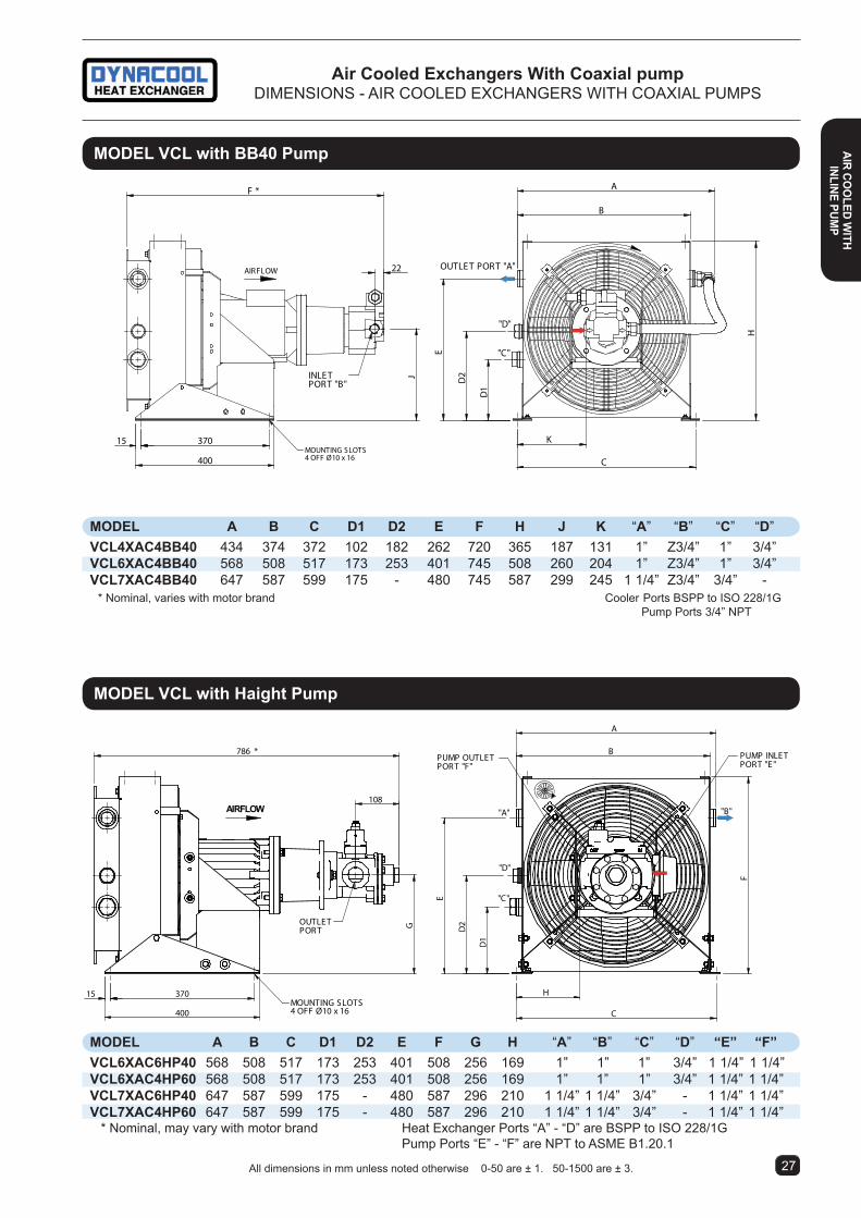
air cooled exchangers With coaxial pumpDiMENSiONS - AiR COOLED EXCHANGERS WiTH COAXiAL PUMPS
moDel Vcl with Haight Pump
moDel a B c D1 D2 e F G H “a” “B” “c” “D” “e” “F”Vcl6xac6HP40 568 508 517 173 253 401 508 256 169 1” 1” 1” 3/4” 1 1/4” 1 1/4”Vcl6xac4HP60 568 508 517 173 253 401 508 256 169 1” 1” 1” 3/4” 1 1/4” 1 1/4”Vcl7xac6HP40 647 587 599 175 - 480 587 296 210 1 1/4” 1 1/4” 3/4” - 1 1/4” 1 1/4”Vcl7xac4HP60 647 587 599 175 - 480 587 296 210 1 1/4” 1 1/4” 3/4” - 1 1/4” 1 1/4” * Nominal, may vary with motor brand Heat Exchanger Ports “A” - “D” are BSPP to iSO 228/1G Pump Ports “E” - “F” are NPT to ASME B1.20.1
"B"
MOUNTING SLOTS4 OFF Ø10 x 16
AIRFLOW
15 370
400
H
C
786 *
G
B
AF
D1
D2
E
OUTLETPOR T
108"A"
"D"
"C"
PUMP OUTLETPOR T "F"
PUMP INLETPORT "E"
MOUNTING S LOTS4 OFF Ø10 x 16
AIRFLOW
15 370
400
K
C
F *
J
B
A
H
D1
D2
E
INLETPORT "B"
22 OUTLE T PORT "A"
"D"
"C"
moDel Vcl with BB40 Pump
moDel a B c D1 D2 e F H J K “a” “B” “c” “D”Vcl4xac4BB40 434 374 372 102 182 262 720 365 187 131 1” Z3/4” 1” 3/4”Vcl6xac4BB40 568 508 517 173 253 401 745 508 260 204 1” Z3/4” 1” 3/4”Vcl7xac4BB40 647 587 599 175 - 480 745 587 299 245 1 1/4” Z3/4” 3/4” - * Nominal, varies with motor brand Cooler Ports BSPP to iSO 228/1G Pump Ports 3/4” NPT
2726
air coo
leD WitH
inline PUmP
air
coo
leD
Wit
H in
line
PUm
P
All dimensions in mm unless noted otherwise 0-50 are ± 1. 50-1500 are ± 3.

2928
moDel Dc31 & Dc32 with Haight Pump
moDel a B c D e F* H K “a” “B” “c” “D” “e”Dc31YH5ac4HP70 680 417 620 255 660 921 760 216 1 1/4” 1 1/4” 1 1/4” 1 1/2” 1 1/2”Dc31YH5ac4HP95 680 417 620 255 660 921 760 216 1 1/4” 1 1/4” 1 1/4” 1 1/2” 1 1/2”Dc32YH6ac4HP70 845 506 785 255 840 936 940 298 1 1/4” 1 1/4” 1 1/4” 1 1/2” 1 1/2”Dc32YH6ac4HP125 845 506 785 255 840 936 940 298 1 1/4” 1 1/4” 1 1/4” 1 1/2” 1 1/2” * Nominal, may vary with motor brand Heat Exchanger Ports “A” - “C” are BSPP to iSO 228/1G Pump Ports “D” - ”E” are NPT to ASME B1.20.1
AIR FLOW
G
C
75 D
H
A
(2) Lifting Eye Bolts Ø14WLL 250 kg Each
200 340600
Ø10 x 25 Slots
"B""A"
"C"
F
30
B
112
K22
Pump InletPort "D"
Pump OutletPort "E"
E
All dimensions in mm unless noted otherwise 0-50 are ± 1. 50-1500 are ± 3.
moDel Dc31 with BB40 Pump
moDel a B c D e F* H K “a” “B” “c” “D” “e”Dc31YH5ac4BB40 680 422 620 257 660 825 760 255 1 1/4” Z3/4” 1 1/4” Z3/4” 1 1/4” * Nominal, varies with motor brand Cooler Ports BSPP to iSO 228/1G Pump Ports 3/4” NPT
AIRFLOW
600
20030
F *
B
A
D
E
C
K
H
PORT OUTLET "A"
PUMP OUTLET "D"
PORT "E "
340 MOUNTING SLOTS6 OFF Ø10 x 25
PUMP INLE T "B"
22
"C"
(2) Lifting Eye Bolts Ø14WLL 250 kg Each
air cooled exchangers With coaxial pumpDiMENSiONS - AiR COOLED EXCHANGERS WiTH COAXiAL PUMPS
air
coo
leD
Wit
H in
line
PUm
P
air coo
leD WitH
inline PUmP
air
coo
leD
Wit
H in
line
PUm
P

ROTATION
119.
511
2513
66
30470370900
28 11401196
(2) LIFT LUGSWLL 125kg EACH
(2) EYEBOLTSWLL 230kg EACH
HEAT EXCHANGER PORTG2"
PUMP INLET
PUMP OUTLET
(6) MOUNTING HOLES 0 14
PUMP MOTOR
HEAT EXCHANGERFAN MOTOR
HEAT EXCHANGER PORTG2"
2928
air coo
leD WitH
inline PUmP
air
coo
leD
Wit
H in
line
PUm
P
air cooled exchangers With coaxial pumpDiMENSiONS - AiR COOLED EXCHANGERS WiTH COAXiAL PUMPS
(4) Ø14 HolesFor Mounting
AIRFLOW
60955
583
"A"
"B" "C"
5233075
1140
1202
477
112
682
119.
511
25
1366
.3
1196
28
Pump OutletPort "E"
Pump InletPort "D"
(2) Lifting Eye BoltsWLL 125 kg Each
moDel Dc35 with Haight Pump
moDel “a” “B” “c” “D” “e”Dc35GH6ac4HP125 2” 2” 3/4” 1 1/2” 1 1/2” * Nominal, may vary with motor brand Heat Exchanger Ports “A” - “C” are BSPP to iSO 228/1G Pump Ports “D” - ”E” are NPT to ASME B1.20.1
All dimensions in mm unless noted otherwise 0-50 are ± 1. 50-1500 are ± 3.
air cooled exchangers With Pump/ motor assembly
Air Cooled Heat Exchangers with pump/motor packages are available. These units provide greater flexibility in demanding situations. Units can be supplied with different fan sizes and different oil flow combinations across our DC31, 32, 33 & 35 models and ST75 & 110 models. Heat exchangers can be fitted with thermostatic or VSD control on the fan motors for energy savings; whilst maintaining constant oil flow. Contact our Sales Office with your application.
Model shown is a DC35LHAC6PP with 80UR Haight Pump.

Air cooled oil heat exchangers for use where the standard aluminium element type oil coolers are not acceptable for the following reasons.
• Circuits where higher pressures are expected to be encountered.
• Where the atmosphere or the process fluids are not compatible with aluminium.
• Where explosive environments prevent the use of aluminium. Eg :- Coal Mines.
• Where lower internal film coefficient is required for use with higher viscosity oils.
• Where heavy dust laden environments exist. These units have anticlogging type fins
BaSic moDel nUmBer = 40, 50, 75 & 110 etc.
coolinG element tYPer = Steel fin, copper tubes, steel tanks - Operating pressure 20 Bar
Port orientationH = Horizontal. V = Vertical
Fan Diameter (mm)4 = Ø4505 = Ø5006 = Ø6308 = Ø8009 = Ø900
BaSic DriVe tYPeac = 3 Phase electric motoraD = 1 Phase electric motorHF = Hydraulic orbit motor with end portsHQ = Hydraulic orbit motor with side ports (Optional)HV = Hydraulic vane motorHx = No motor (hydraulic motor mounting provided. Customer to specify motor details)nm = No motor (electric motor mounting provided) Ga = Air motor
motor SPeeD4 = 4 Pole Nom. 1450rpm at 50 Hz6 = 6 Pole Nom. 950rpm at 50 Hz8 = 8 Pole Nom. 750rpm at 50 Hz
SPecial DetailS or FiniSH00 or none = 415V 50Hz01 = 240V 50Hz0a = with antistatic fan with silumin retainers (Not suitable for underground coal mine use)0c = with antistatic fan with steel or zinc retainers (Suitable for underground coal mine use)0r = with relief valve.
# not all combinations are available or possible
St 75 r H 8 ac 6 00 #SERiES ‘S’ MODEL CODESSerieS ST
* Noise levels listed are raw A weighted pressure representing worst case. Refer noise level statement page 65.# Also available with 240 volt single phase electric motor.† Models with Ø900 fan available with optional antistatic blades and aluminium retainers only.
TECHNiCAL SPECiFiCATiONS - STEEL CORE AC ELECTRiC MODELS
Special application air cooled oil coolers
moDel/ noise level * Fan Ø Volts Phase kW Size Poles Weight Part number dB(a) at 1m (mm) (kg) ST40RH4AC400# 84 450 415 3 0.55 80 4 44 ST50RH5AC400# 86 500 415 3 0.75 80 4 60 ST75RH6AC400 89 630 415 3 1.5 90L 4 140 ST75RH8AC400 96 800 415 3 2.2 100L 4 149 ST75RH8AC600 88 800 415 3 2.2 112M 6 150 ST75RH9AC600† 88 900 415 3 2.2 112M 6 150 ST110RH8AC400 96 800 415 3 3 100L 4 275 ST110RH9AC600† 92 900 415 3 2.2 112M 6 275
air
coo
leD
SPec
ial
aPPl
icat
ion
air coo
leD SPecial aPPlicatio
n
3130

1
234
0.1
0.5ÆP
Bar
100 200 500 1000502010Oil Flow l/min
7
ST75
R
ST40
/50R
ST11
0
0.2
0.3
kW/¡C
0.4
0.5
1.0
2.0
3.0
Oil Flow l/min20 100 200 400
20 100 200 400
50
50
600
600
0.1
0.07
0.15
10 15
10 15
ST40RH4AC4
ST50RH5AC4
ST75RH8AC6ST75RH6AC4
ST110RH8AC4/ST110RH9AC6
ST110RH8AC6
ST75RH8AC4/ST75RH9AC6
20 40 60 80 100 120Oil Viscosity cSt
PC
orre
ctio
n F
acto
r
1
2
3
Special application air cooled oil coolersPERFORMANCE - AC ELECTRiC SERiES ST
oil cooler SiZinGStep 1. Calculate ETD = TOil - TAirTOil= Temp °C of oil entering the cooler (usually the same as max. allowable oil temp.) TAir= Expected Ambient Air Temp°C.Step 2. Calculate kW/°C ETD = kW kW = Heat Load. ETDStep 3. Enter Cooler Performance Tables and select a cooler which meets or exceeds the required performance at the required oil flow rate.Step 4. Check pressure drop of the oil cooler selected in step 3. If the average oil viscosity is not 30 cSt apply a correction for the expected viscosity.Computer model selection program available.
air
coo
leD
SPec
ial
aPPl
icat
ion
air coo
leD SPecial aPPlicatio
n
3130

1120
1067
75 106465055050
(4) HOLESØ14
1219
1186105.9
723 *
997
108
“A”
“B”
AIR FLOW
(2) LIFT LUGSWLL 125kg EACH
Special application air cooled oil coolersDiMENSiONS - AC ELECTRiC SERiES ST
3332
X
AIR
DYNACOOL
A
H E
C
F*
Port "B"
Port "A"
22 B
MSlots Ø10 x 25L
G58
KJD
All ports BSPP to ISO 228/1G *Nominal, Varies with motor brand.All dimensions in mm unless noted otherwise 0-50 are ± 1. 50-1500 are ± 3.
moDel St75
24 952 241000
30 30264324
110
998
58648 *
609
1219
1021
19 MOUNTING HOLES - 4 OFFØ11 X 25 LONG SLOTS
(2) LIFT LUGSWLL 125kg EACH
AIR FLOW
“A”
“B”
*Nominal Varies with motor type. moDel St110
moDel St40 & St50
model a B c D e F* G H J K l m Port a Port B Port c Port D St40r 480 - 432 107 475 518 276 615 75 50 324 264 1 1/4” 1 1/4” - - St50r 545 21 496 107 615 505 276 755 75 50 324 264 1 1/4” 1 1/4” - - *Nominal Varies with motor type. Ports BSPP to ISO 228/1G
St75 Port size “a” “B” 2” 2”
St110 Port size “a” “B” 2” 2”
air
coo
leD
SPec
ial
aPPl
icat
ion
air coo
leD SPecial aPPlicatio
n

3332
air
coo
leD
SPec
ial
aPPl
icat
ion
air coo
leD SPecial aPPlicatio
n
Special application air cooled oil coolersAC ELECTRiC SERiES ST WiTH CO-AXiAL PUMP
TECHNiCAL SPECiFiCATiONS - STEEL CORE AC ELECTRiC MODELS
MODEL/ Oil Flow Fan Ø Volts Phase kW Size Poles Part number l/min (mm) ST40RH4AC4BB40 40 450 415 3 1.5 90 4 ST50RH5AC4HP49 49 500 415 3 3 100L 4 ST75RH6AC4HP125 127 630 415 3 4 112M 4
AIR FLOW
24
766 *
349
30 200 140
400
PUMP INLET3/4" NPT
MOUNTING SLOTS6 OFF O11 x 25
158
69
482
PUMP OUTLET3/4" NPT
69
287
615
107
476
27PORT "A"
PORT "B"
• High performance off-line systems for oil cooling of hy-draulics or gear drives in hostile environments.
• internal relief valve for protection against over pressure or accident.
aPPlication. Similarly to our VCL & DC range, the ST coaxial pump units are also effective for remote cooling of hydraulic circuits, or lube oil cooling for gear drives. The ST range can be manufactured to underground coal mine specification.
PUmP PreSSUre. Pump delivery pressure to 5 bar. Higher pressure ratings are available. Consult factory.
PerFormance ranGe. Heat transfer range is from 0.25 to 1.4 kW/°C of ETD. Performance is based on ISO 68 hydraulic oil at 30cSt, for other fluids and viscosities please contact our sales office. ETD is the difference between the entering oil and the cooling air temperature.
connection. Please contact our sales office if the pumping head is greater than 10m or you have any special requirements. Pump inlet must be flooded.
moDel St40 WitH BB40 co-axial PUmP

moDel DFm22
• Rugged high strength design
• High pressure round tube construction
• Damage resistant steel fins and tanks.
OIL FLOW - LITRES/MIN
kW H
EAT
REM
OVE
D
4
5
6
7
8
910
15
20
25
30
10 15 20 25 30 40 50 60 70 80 90 100 150 200 250 300 400 500
OIL VISCOSITY - cSt.
OIL
P M
ULT
IPLI
ER
1
1.5
2
2.5
3.0
4.0
5.0
10 15 20 25 30 40 50 60 80 100
OIL PRESSUREDROP
= 0.5 Bar = 1.0 Bar
DFM - 12
DFM - 22
DFM - 11
moDelS DFm11 & DFm12 moDel DFm22
DimenSionS - DFm
PerFormance - DFm
• Pressure rating 21 Bar • Min. burst pressure 62 Bar All ports BSPP to iSO 228/1G
Special application air cooled oil coolersSPECiFiCATiONS - STANDARD DC ELECTRiC MOBiLE SERiES DFM
E
J
K
FBD
G
C
A
4 HolesØ13.5
MotorPowerLead
L (2 Places)
Air
# G3/4"
FAN
A
D
KJ
EB
F
G
C
4 HolesØ13.5
Motor PowerLeads
L (2 Places)
Air
G3/4"
FAN FAN
Based on iSO-VG32 oil entering 50°C higher than ambient air (50°C ETD)
applications - Concrete Transit Mixers, Concrete Pumps, Cranes, Harvesters, Grain Handlers, Off-Road & Con-struction Machines etc.
moDel DFm11
All dimensions in mm unless noted otherwise 0-50 are ± 1. 50-1500 are ± 3.3534
Part no Volts amps a B c D e F G J K l* Wt kg 67/DFm11/12 12 12.5 411 489 130 528 452 38 38 190.5 94 G1” 10 67/DFm11/24 24 6.3 411 489 130 528 452 38 38 190.5 94 G1” 10 67/DFm12/12 12 12.5 433 540 170 578 476 64 76 190.5 94 G1 1/4” 19 67/DFm12/24 24 6.3 433 540 170 578 476 64 76 190.5 94 G1 1/4” 19 67/DFm22/12 12 25 800 540 170 578 476 64 76 362.0 196 G1 1/2” 35 67/DFm22/24 24 12.6 800 540 170 578 476 64 76 362.0 196 G1 1/2” 35
air
coo
leD
SPec
ial
aPPl
icat
ion

3534
Special application air cooled oil coolersTHERMOSTATiC CONTROLS FOR DC ELECTRiC MOBiLE SERiES DFM
Part no Volts amps a B c D e F G J K l* Wt kg 67/DFm11/12r 12 12.5 457 532 130 528 452 38 38 190.5 94 G1” 10 67/DFm11/24r 24 6.3 457 532 130 528 452 38 38 190.5 94 G1” 10 67/DFm12/12r 12 12.5 464 582 170 578 476 64 76 190.5 94 G1 1/4” 19 67/DFm12/24r 24 6.3 464 582 170 578 476 64 76 190.5 94 G1 1/4” 19 67/DFm22/12r 12 25 857 575 170 578 476 64 76 362.0 196 G1 1/2” 35 67/DFm22/24r 24 12.6 857 575 170 578 476 64 76 362.0 196 G1 1/2” 35
moDelS DFm11r & DFm12r moDel DFm22r
DimenSionS - DFm - relieF ValVe moDelS
• Pressure rating 21 Bar • Min. burst pressure 62 Bar
E
J
K
F
B
DG
C
A
4 HolesØ13.5
MotorPowerLead
L (2 Places)
Air
# G3/4"
FAN
FLOW
A
D
KJ
EB
F
G
C
4 HolesØ13.5
Motor PowerLeads
L (2 Places)
Air
G3/4"
FAN FAN
FLO
W
Standard relief valve setting is 2 Bar . Inlet and outlet connections may be reversed when bypass valve is not used.
Thermostats Are An important Addition To DFM Models To Maximise Fan Motor Life
For more information about the 17/DC wet thermoswitch see page 57.
Note ; For optimum performance, the thermoswitch should be located as close to the oil inlet as possible.
17/Dc Wet type. A self contained thermostatically controlled electric switch mounted in a steel bulb well for immersion in the hot process fluid. The switch is usually supplied with normally open contacts. Kits include a fuse, fuse holder, port adaptor S102-1208, relay, wiring and fitting instructions.
Part no. Description
039.8.06173 Thermo Kit 65°c For DFM 11 & 12 in 12 Volt 039.8.06143 Thermo Kit 65°c For DFM 11 & 12 in 24 Volt 039.8.06172 Thermo Kit 55°c For DFM 11 & 12 in 12 Volt 039.8.06142 Thermo Kit 55°c For DFM 11 & 12 in 24 Volt 039.8.06372 Thermo Kit 65°c For DFM 22 in 12 Volt 039.8.06370 Thermo Kit 65°c For DFM 22 in 24 Volt 039.8.06371 Thermo Kit 55°c For DFM 22 in 12 Volt 039.8.06369 Thermo Kit 55°c For DFM 22 in 24 Volt
All dimensions in mm unless noted otherwise 0-50 are ± 1. 50-1500 are ± 3.
air coo
leD SPecial aPPlicatio
n

Motor Enclosures are IP55. Motor Construction to IEC 34-1*Nominal, Varies With Motor BrandFor 60 Hz Models Or Other Voltage/ Frequencies, please consult with our Sales office.Also available with 12 & 24V DC motors & air driven motors.
Notes On SelectionUnderlined models are usually the highest performance lowest cost options. Other models are usually low noise or special application. For more details consult our sales office.
SCFM = Standard Cubic Feet Per Minute.For Standard Cubic Metres Per Minute divide CFM by 35.335
Effectiveness % = T1 - T2 T1 - t1Where: T1 = Air line temp entering cooler. T2 = Air line temp leaving cooler. t1 = Design ambient air temp to fan.
∆P Column = Pressure drop of the air through the aftercooler in lbs per square inch at the air flow shown in “SCFM 85%” column. Higher air flows than stated may be passed through most models. However, effectiveness % will reduce and ∆P will increase.
Data is valid for air pressure in the 100 PSIG (6.9 BAR) Range.
air after coolers With aluminium cooling elementsVERSACOOL AND DYNACOOL MODELS
model Vcl7xac50
air
aFte
r co
ole
rS
3736
MODEL/ ∆P Noise level * Fan Ø Volts Phase kW Size Poles Weight Part Number PSiG (max) dB(A) at 1m (mm) (kg) VC2XAC50 4.8 82 243 415 3 0.25 63 2 12 VC2XAD50 4.8 82 243 240 1 0.24 63 2 12 VC2XAG50 2.6 65 243 415 3 0.18 63 4 12 VC2XAH50 2.6 65 243 240 1 0.15 63 4 12 VCL4XAC50 0.7 84 305 415 3 0.37 71 2 20 VCL4XAD50 0.7 84 305 240 1 0.37 71 2 20 VCL5NAC50 1.4 87 354 415 3 0.75 80 2 30 VCL5NAD50 1.4 87 354 240 1 0.75 80 2 30 VCL5NAG50 0.7 71 354 415 3 0.37 71 4 26 VCL5NAH50 0.7 71 354 240 1 0.37 71 4 26 VCL6XAC50 1.8 78 450 415 3 0.55 80 4 37 VCL6XAD50 1.8 78 450 240 1 0.55 80 4 37 VCL7XAC50 3.5 78 450 415 3 0.55 80 4 39 VCL7XAD50 3.5 78 450 240 1 0.55 80 4 39 DC31YH5AC400 4.3 84 500 415 3 0.75 80 4 68 DC32SH6AC400 3.0 89 630 415 3 1.5 90L 4 90 DC33VH6AC400 5.1 89 630 415 3 1.5 90L 4 180 DC35LH9AC600 5.4 92 892 415 3 2.2 112 6 210

air after coolers With aluminium cooling elementsPERFORMANCE CHARTS
3736
air aFter coo
lerS
80828486889092949698
100
0 100 200 300 400SCFM
Versacool 3 Phase 415V 50Hz
VCL5NAG50 VCL6XAC50 VCL7XAC50VCL5NAC50VCL4XAC50
VC2XAC50VC2XAG50
% E
ffect
iven
ess
80828486889092949698
100
0 50 100 150 200 250 300 350 400SCFM
Versacool 1 Phase 240V 50 Hz
VC2XAH50VC2XAD50
VCL4XAD50VCL5NAD50
VCL5NAH50VCL6XAD50 VCL7XAD50
% E
ffect
iven
ess
88.0
90.0
92.0
94.0
96.0
98.0
100.0
0 1 2 3 4 5 6
ΔP PSI
% E
ffect
iven
ess
DC31YV5AC402
DC32SV6AC400
DC33VH6AC400
DC35LH9AC600
88
90
92
94
96
98
100
102
100 300 500 700 900 1100 1300
SCFM
Dynacool 3 Phase 415V 50 Hz
DC31YV5AC402
DC32SV6AC400
DC33VH6AC400
DC35LH9AC600
% E
ffect
iven
ess

air after coolers With aluminium cooling elementsSPECiFiCATiONS - VERSACOOL & DYNACOOL MODELS
air
aFte
r co
ole
rS
3738
moDel Dc31YV & Dc32SV
Pressure Rating14 BAR (200 PSiG)
model a B c D e F G H J* “a” “B” “c” Dc31YV 685 806 739 635 229 787 275 60 512 1 1/4” 1 1/4” 1 1/4” Dc32SV 863 983 917 584 152 965 298 71 573 2” 2” 3/4” *Nominal, Varies with motor brand. BSPP to iSo 228/1G
4-Off Ø10 x 16 LongMounting SlotsTop & Bottom
AIRFLOW
E
A1
A2
BH 105 G*14 77 14
D1
D2
C
F1
F2
J
"A""B"
"D"
"C"
model a1 a2 B c D1 D2 e F1 F2 G* H J liq Vol l “a” “B” “c” “D” Vcl4xa 340 - 312 259 99 179 360 22 18 162 65 88 1.2 1” 1” 1” 3/4”# Vcl5na 440 400 412 335 107 187 440 22 18 175 65 100 1.8 1” 1” 1” 3/4” Vcl6xa 485 468 457 398 170 250 505 22 18 175 65 100 2.2 1” 1” 1” 3/4” Vcl7xa 567 545 539 477 172 - 584 12 - 175 65 100 2.5 1 1/4” 1 1/4” 3/4” - *Nominal, Varies with motor brand. All ports BSPP to ISO 228/1G
See Accessory information for foot bracket options.
Vc4, Vc5n, Vc6x & Vc7x moDel
Vc2x moDel PortS DoWn
"B" "A"
"C"
240*248
318
280
7 6077
10535
FAN
AIR
16 x Ø10 slots
308 Flexible hose requiredPorts A & B are Male JIC 37° flare UN. Port C is BSPP to ISO 228/1G*Nominal, Varies with motor brand.
All dimensions in mm unless noted otherwise 0-50 are ± 1. 50-1500 are ± 3.
VC2XA Port size “A” “B” “C” 1 1/16” 1 1/16” 1/2”
AIRFLOW
ROTATION
(2) Lifting Eye BoltsØ14WLL 250 kG Each
Ø10 x 25 Slotsfor Mounting
GJ*
A
B
38 340408
E
F
175
30 REF. C 24
Port “A”
Port “B”Port “C”
24
H
D
37 37

moDel Dc33
moDel Dc35l
Pressure Rating 20 BAR (290 PSiG)
Pressure Rating14 BAR (200 PSiG)
(4) Ø14 HolesFor Mounting
AIR FLOW
706*
583
120
1030
1195
1061
1066
"A"
"B"
"C"
75
523
72
101028 30
77
Lifting LugWLL 125kg each
All dimensions in mm unless noted otherwise 0-50 are ± 1. 50-1500 are ± 3.
(4) Ø14 HolesFor Mounting
AIRFLOW
G=60.0L=72.5
G=690*L=710*
583119.
511
25
1289
1192
1140
1196
"A"
"B""C"
5233028
75
77
Lifting LugsWLL 125kg Each
Dc35 Port size “a” “B” “c” 2” 2” 3/4”
Dc33 Port size “a” “B” “c” 2” 2” 3/4”
3738
air after coolers With aluminium cooling elementsSPECiFiCATiONS - DYNACOOL MODELS
Air Flowm/s2.002.553.003.504.005.557.50
10.0012.50
1 RowCore2536435565105174274473
2 RowCore527394118144212473652747
in. H2O = Pa x 0.004
Table 6: Air StaticPressure Drop For AirFace Velocity In Pa
=========
2.002.553.003.504.005.557.5010.0012.50
0.6400.7100.7700.8000.8501.0001.1491.2241.337
Table 3: Heat TransferCorrection Factors
for Air Face VelocityIn Metres Per Second
35
30
2550050 100 150 200 2500 300 350 400 450 550
45
40
50
55
0.73BAR
1.46BAR
2.90BAR
4.35BAR
Table 4:Pressure Drop SymbolsPressure Drop BAR @ 30cSt
ISO 68 Oil at 58c (136f)x 14.5 for PSI
Part No67/649S8H
& 67/670S8H
Table 5: Pressure Drop FactorsCorrections For Oil Viscosity
Litres Per Minute Oil Flow
25
15
10
0
20
5Part No
67/073S2LThrough
67/524S5H
Hea
t rem
oval
kW a
t 30C
ETD
Table 1
25 50 75 100 125 150 175 200 225 2500 275
Hea
t rem
oval
kW a
t 30C
ETD
Table 2
Litres Per Minute Oil Flow
20 40 60 80 100120Oil Viscosity cSt
P
Cor
rect
ion
Fac
tor
1
2
3
15.
5, 10.
14.
16.
8, 13.
6, 7, 11 ,12
9.
3. 4.1, 2.
17.
18.
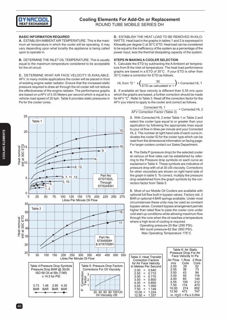
D. ESTABLiSH THE HEAT LOAD TO BE REMOVED iN KiLO-WATTS. Heat load in the graphs in tables 1 and 2 is expressed in Kilowatts per degree C at 30°C ETD. Heat load can be considered to be equal to the inefficiency of the system as a percentage of the power input, less the thermal dissipating capacity of the system.
StePS in maKinG a cooler Selection1. Calculate the ETD by subtracting the A Ambient air tempera-ture from B the inlet oil temperature. The heat load performance graphs are based in a ETD of 30°C . If your ETD is other than 30°C make a correction for ETD as follows.
2. If available air face velocity is different than 5.55 m/s upon which the graphs are based, a further correction should be made for AFV “C”. Refer to Table 3. Read off the correction factor for the AFV you intend to apply to the cooler and correct as follows.
3. With Corrected HL 2 enter Table 1 or Table 2 and select the cooler type equal to or greater than your application by following the appropriate lines equal to your oil flow in litres per minute and your Corrected HL 2. The number at right hand side of each curve in-dicates the cooler iD for the cooler type which can be read from the dimensional information on facing page. For larger coolers contact our Sales Department.
4. The Delta P (pressure drop) for the selected cooler at various oil flow rates can be established by refer-ring to the Pressure drop symbols on each curve as explained in Table 4. These symbols are indicative of pressure drop with oil at 30 cSt viscosity. Corrections for other viscosities are shown on right hand side of the graph in table 5. To correct, multiply the pressure drop established from the graph symbols by the cor-rection factor from Table 5.
5. Most of our Mobile Oil Coolers are available with optional full flow built in bypass valves. Factory std. 2 BAR or optional 4 BAR springs available. Under most circumstances these units may be used as constant bypass valves. Constant bypass arrangement permits higher than rated flow to pass the cooler core under cold start up conditions while allowing maximum flow through the core when the oil reaches a temperature where a high level of cooling is required.
Operating pressure-20 Bar (290 PSI).Min burst pressure-62 Bar (900 PSi),Max Operating Temperature 176˚C
BaSic inFormation reQUireDa. ESTABLISH AMBIENT AIR TEMPERATURE. This is the maxi-mum air temperature in which the cooler will be operating. It may vary depending upon what locality the appliance is being called upon to operate in.
B. DETERMINE THE INLET OIL TEMPERATURE. This is usually equal to the maximum temperature considered to be acceptable for the oil circuit.
c. DETERMINE WHAT AIR FACE VELOCITY IS AVAILABLE. AFV. In many mobile applications the cooler will be placed in front of existing engine water radiator. Ensure that the increased static pressure required to draw air through the oil cooler will not reduce the effectiveness of the engine radiator. The performance graphs are based on a AFV of 5.55 Meters per second which is equal to a vehicle road speed of 20 kph. Table 6 provides static pressures in Pa for the cooler cores.
cooling elements For add-on or replacementROUND TUBE MOBiLE SERiES DH
30(ETD as calculated in 1HL from “D “ x ) = Corrected HL 1
AFV Correction Factor (Table 3)= Corrected HL 2 Corrected HL 1
coo
linG
ele
men
tS
4140
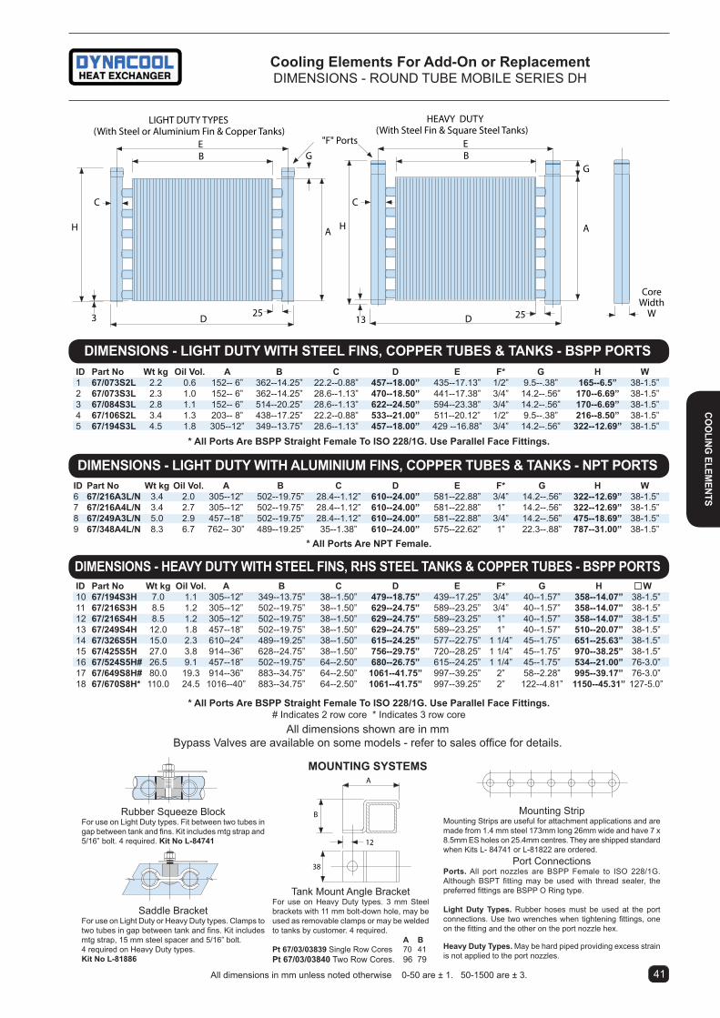
cooling elements For add-on or replacementDiMENSiONS - ROUND TUBE MOBiLE SERiES DH
A
B
38
12
25
H A
G
EB
C
D
CoreWidth
W
H
C
D
A
G
LIGHT DUTY TYPES (With Steel or Aluminium Fin & Copper Tanks)
HEAVY DUTY (With Steel Fin & Square Steel Tanks)
25
"F" Ports
3 13
EB
Rubber Squeeze BlockFor use on Light Duty types. Fit between two tubes in gap between tank and fins. Kit includes mtg strap and 5/16” bolt. 4 required. Kit no l-84741
Saddle BracketFor use on Light Duty or Heavy Duty types. Clamps to two tubes in gap between tank and fins. Kit includes mtg strap, 15 mm steel spacer and 5/16” bolt.4 required on Heavy Duty types. Kit no l-81886
Mounting StripMounting Strips are useful for attachment applications and are made from 1.4 mm steel 173mm long 26mm wide and have 7 x 8.5mm ES holes on 25.4mm centres. They are shipped standard when Kits L- 84741 or L-81822 are ordered.
Port ConnectionsPorts. All port nozzles are BSPP Female to ISO 228/1G. Although BSPT fitting may be used with thread sealer, the preferred fittings are BSPP O Ring type.
light Duty types. Rubber hoses must be used at the port connections. Use two wrenches when tightening fittings, one on the fitting and the other on the port nozzle hex.
Heavy Duty types. May be hard piped providing excess strain is not applied to the port nozzles.
moUntinG SYStemS
Tank Mount Angle BracketFor use on Heavy Duty types. 3 mm Steel brackets with 11 mm bolt-down hole, may be used as removable clamps or may be welded to tanks by customer. 4 required. a BPt 67/03/03839 Single Row Cores 70 41Pt 67/03/03840 Two Row Cores. 96 79
* all Ports are BSPP Straight Female to iSo 228/1G. Use Parallel Face Fittings.# Indicates 2 row core * Indicates 3 row core
DimenSionS - liGHt DUtY WitH Steel FinS, coPPer tUBeS & tanKS - BSPP PortS
DimenSionS - HeaVY DUtY WitH Steel FinS, rHS Steel tanKS & coPPer tUBeS - BSPP PortS
iD Part no Wt kg oil Vol. a B c D e F* G H W6 67/216a3l/n 3.4 2.0 305--12” 502--19.75” 28.4--1.12” 610--24.00” 581--22.88” 3/4” 14.2--.56” 322--12.69” 38-1.5”7 67/216a4l/n 3.4 2.7 305--12” 502--19.75” 28.4--1.12” 610--24.00” 581--22.88” 1” 14.2--.56” 322--12.69” 38-1.5”8 67/249a3l/n 5.0 2.9 457--18” 502--19.75” 28.4--1.12” 610--24.00” 581--22.88” 3/4” 14.2--.56” 475--18.69” 38-1.5”9 67/348a4l/n 8.3 6.7 762-- 30” 489--19.25” 35--1.38” 610--24.00” 575--22.62” 1” 22.3--.88” 787--31.00” 38-1.5”
* all Ports are nPt Female.
DimenSionS - liGHt DUtY WitH alUminiUm FinS, coPPer tUBeS & tanKS - nPt PortS
All dimensions shown are in mmBypass Valves are available on some models - refer to sales office for details.
iD Part no Wt kg oil Vol. a B c D e F* G H W1 67/073S2l 2.2 0.6 152-- 6” 362--14.25” 22.2--0.88” 457--18.00” 435--17.13” 1/2” 9.5--.38” 165--6.5” 38-1.5”2 67/073S3l 2.3 1.0 152-- 6” 362--14.25” 28.6--1.13” 470--18.50” 441--17.38” 3/4” 14.2--.56” 170--6.69” 38-1.5”3 67/084S3l 2.8 1.1 152-- 6” 514--20.25” 28.6--1.13” 622--24.50” 594--23.38” 3/4” 14.2--.56” 170--6.69” 38-1.5”4 67/106S2l 3.4 1.3 203-- 8” 438--17.25” 22.2--0.88” 533--21.00” 511--20.12” 1/2” 9.5--.38” 216--8.50” 38-1.5”5 67/194S3l 4.5 1.8 305--12” 349--13.75” 28.6--1.13” 457--18.00” 429 --16.88” 3/4” 14.2--.56” 322--12.69” 38-1.5”
* all Ports are BSPP Straight Female to iSo 228/1G. Use Parallel Face Fittings.
All dimensions in mm unless noted otherwise 0-50 are ± 1. 50-1500 are ± 3.
A
B
38
12
25
H A
G
EB
C
D
CoreWidth
W
H
C
D
A
G
LIGHT DUTY TYPES (With Steel or Aluminium Fin & Copper Tanks)
HEAVY DUTY (With Steel Fin & Square Steel Tanks)
25
"F" Ports
3 13
EB
iD Part no Wt kg oil Vol. a B c D e F* G H W10 67/194S3H 7.0 1.1 305--12” 349--13.75” 38--1.50” 479--18.75” 439--17.25” 3/4” 40--1.57” 358--14.07” 38-1.5”11 67/216S3H 8.5 1.2 305--12” 502--19.75” 38--1.50” 629--24.75” 589--23.25” 3/4” 40--1.57” 358--14.07” 38-1.5”12 67/216S4H 8.5 1.2 305--12” 502--19.75” 38--1.50” 629--24.75” 589--23.25” 1” 40--1.57” 358--14.07” 38-1.5”13 67/249S4H 12.0 1.8 457--18” 502--19.75” 38--1.50” 629--24.75” 589--23.25” 1” 40--1.57” 510--20.07” 38-1.5”14 67/326S5H 15.0 2.3 610--24” 489--19.25” 38--1.50” 615--24.25” 577--22.75” 1 1/4” 45--1.75” 651--25.63” 38-1.5”15 67/425S5H 27.0 3.8 914--36” 628--24.75” 38--1.50” 756--29.75” 720--28.25” 1 1/4” 45--1.75” 970--38.25” 38-1.5”16 67/524S5H# 26.5 9.1 457--18” 502--19.75” 64--2.50” 680--26.75” 615--24.25” 1 1/4” 45--1.75” 534--21.00” 76-3.0”17 67/649S8H# 80.0 19.3 914--36” 883--34.75” 64--2.50” 1061--41.75” 997--39.25” 2” 58--2.28” 995--39.17” 76-3.0”18 67/670S8H* 110.0 24.5 1016--40” 883--34.75” 64--2.50” 1061--41.75” 997--39.25” 2” 122--4.81” 1150--45.31” 127-5.0”
4140
coo
linG elem
entS

Part No Type A B C D E J K F G L H W Max Flow Heat* Weight Oil Cat. mm mm mm mm mm mm mm mm mm l/min cap. kW kg Vol. (l)21/05030 c - - - - - - - - - - - - 60 9 5.8 21/04778 a 295 330 203 13 65 160 - 1” 1” 3/4” 262 250 140 6.5 6 1.3 418/05824 a 365 400 203 13 65 228 80 1” 1” 3/4” 336 352 150 - 8 2.0 521/04779 a 432 467 203 13 65 229 - 1” 1” 3/4” 397 403 180 14 10 2.5 621/04994 a 514 543 203 13 65 305 - 1 1/4” 3/4” - 473 479 200 23 13.5 3.2 71e2926 a 622 635 355 10 65 406 - 1 1/4” 1 1/4” - 565 578 240 33 21 4.4 311e2927 a 800 801 508 10 65 585 - 1 1/4” 1 1/4” - 730 755 300 55 30 6.5 3221/04996 a 800 821 508 13 90 663 - 2” 3/4” - 731 764 400 - 33.0 7.7 3221/05031S B 1086 1114 813 12 95 984 - 2” 3/4” - 1076 1086 570 - 81.0 24.6 3518/05828 B 1086 1115 813 13 70 986 - 2” 3/4” - 1045 1086 - - 63.0 17.9 3518/06507 D 1205 1181 400 13 70 1125 - 2” 3/4” - 1045 1086 - - 63.0 17.9 3518/06524 D 1205 1181 400 13 95 1125 - 2” 3/4” - 1045 1086 570 - 81.0 24.6 35Ports for all coolers listed above are BSPP to ISO 228/1G. * Heat capacity is at max oil flow, airflow of 5.1 m/s velocity through the core and oil/air inlet temp. difference of 30°C
Part No New Equivalent Cross reference Old OEM (BSP) Other (NPT)1e4018 21/04778 66/01/00258 1E2922 1E29281e2924 21/04779 66/01/00259 - 1E29291e2926 66/01/00950 - 1E29311e2927 66/01/00951 - 1E29321e4041 18/05828 66/01/03712 3560 (Ext’d tank) 1E2966
caution: Some original model coolers were supplied with NPT threaded ports. All new coolers have BSPP threaded ports. BSPP ports have a groove machined on the OD to assist in identifying the thread.
cooling elements For add-on or replacementPFA AND ALUMiNiUM CORES
All dimensions in mm unless noted otherwise 0-50 are ± 1. 50-1500 are ± 3. 4342
coo
linG
ele
men
tS
tYPe c
313
473
509
543
626595
102
106
3/4"40
19
Ø12.7
40
Hi-FloW SerieS alUminiUm coreS - 14 Bar
C
WA
HB
ØD
E
F
L
F
G
J
K
#
A(W)
HB
C
E
ØD
FF
G
J
tYPe a
tYPe B
# Some older models have a single flange
• 14 bar Pressure rating • Very low pressure drop • Suitable as air aftercooler
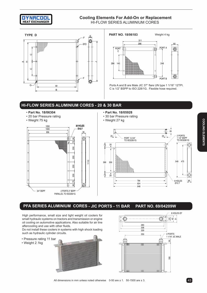
Weight 4 kg
311286 60
PORT APORTC
PORT B
145288 248
Ports A and B are Male JIC 37° flare UN type 1 1/16” 12TPI. C is 1/2” BSPP to ISO 228/1G. Flexible hose required.
Part no. 18/06183
PFa SerieS alUminiUm coreS - Jic PortS - 11 Bar Part no. 69/04209W
• Pressure rating 11 bar• Weight 2.1kg
High performance, small size and light weight oil coolers for small hydraulic systems on tractors and transmission or engine oil cooling on automotive applications. Also suitable for air line aftercooling and use with other fluids. Do not install these coolers in systems with high shock loading such as hydraulic cylinder circuits.
30
283
329
514219
0
8 HOLES Ø7
308
22
2 PORTS 1 1/16" JIC MALE
250
65
65
20
20
8 HOLES Ø12.7
2 PORTS 1 1/2" BSPPTO ISO228/1G
20 25
784824848
359399
75
75
549 475
PORT G 3/4"TO ISO228/1G
• Part no. 18/05928 • 30 bar Pressure rating • Weight 27 kg
Hi-FloW SerieS alUminiUm coreS - 20 & 30 Bar
200
200
200
3/4" BSPP
8080
95
1110
2 PORTS 2" BSPPPARALLEL TO ISO228/1G
7520
075
20 HOLESØ12.7
10501000956
• Part no. 18/06304 • 20 bar Pressure rating • Weight 75 kg
4342
cooling elements For add-on or replacementHi-FLOW SERiES ALUMiNiUM CORES
All dimensions in mm unless noted otherwise 0-50 are ± 1. 50-1500 are ± 3.
coo
linG elem
entS
A J
B
W
E
CC
F
F
G
ØD
H
tYPe D

Maximum Flow Rates
Unit Shell Side tube Side litres/min. Size Litres/Min. One Pass Two Pass Four Pass
25EK 75 50 23 N/A 35EK 225 90 45 23 50EK 302 212 106 53ratings
Maximum shell side pressure. . . . . . . 35 Bar Maximum tube side pressure. . . . . . . . 10 Bar Maximum temperature. . . . . . . . . . . . . 120°C
EK SeriesWater cooled - industrial Heat exchangersEK SERiES - EXTENDED SURFACE
Selection procedureStep 1. Determine the Heat load.This will vary with different systems, but typically coolers are sized to remove 25 to 50% of the system’s input total maximum power rating. (Example: 75kW Power Unit x .33 = 25kW Heat Load)Step 2. Determine approach temperature.Desired exit oil temp°C - Water inlet temp°C = Actual Approach Step 3. Determine curve kW Heat load.Enter the information from above:kW heat load x 25 x Viscosity Correction A = Curve kW load Actual approachStep 4. Find curve operating Point.Locate on the graph the point determined by the oil flow and the curve kW heat load. Any cooler curve above this point will have sufficient capacity.Step 5. Determine oil Pressure Drop from curves. = 0.5 Bar = 1.0 Bar = 2.0 BarMultiply pressure drop from curve by correction factor B found on oil vis-cosity correction curve.
Performance curves are based on iSO VG 32 oil leaving the cooler 25°C higher than the incoming water temperature used for cooling. This is also referred to as a 25°C approach temperature.
materialsShell............................ Steel Tubes .......................... Copper/NickelTubesheets ................. Steel Baffles......................... SteelFins ............................. AluminiumMounting Brackets ...... SteelEnd Caps .................... Grey ironGaskets ...................... Nitrile Rubber/Cellulose FibreNameplate .................. Aluminium Foil
• Extended surface to minimise water consumption
• Corrosion resistant 90/10 copper nickel tubes as standard (Cu optional)
• Water Flow Controls are available as options see pages 59 to 62
• Surge-Cushion The Surge-Cushion® is a protective device (patented) designed to internally bypass a portion of the oil flow during cold start conditions, or when sudden flow surges temporarily exceed the maximum flow allowed for a given cooler. This device may replace an external bypass valve, but it is not intended to bypass the total oil flow.
tecHnical SPeciFicationS
Models Part no Wt kg
1. 25EK1/1 65/eK508oS* 3.0 2. 25EK1/2 65/eK508tS* 3.1 3. 25EK4/1 65/eK514oS* 5.0 4. 25EK4/2 65/eK514tS* 5.0 5. 35EK1/1 65/eK708o 6.2 6. 35EK1/2 65/eK708t 6.2 7. 35EK2/1 65/eK712o 7.2 8. 35EK2/2 65/eK712t 7.2 9. 35EK4/1 65/eK718o 8.4 10. 35EK4/2 65/eK718t 8.4 11. 50EK2/1 65/eK1012o 16.6 12. 50EK2/2 65/eK1012t 16.6 13. 50EK4/1 65/eK1018o 19.1 14. 50EK4/2 65/eK1018t 19.1 15. 50EK5/1 65/eK1024o 22.2 16. 50EK5/2 65/eK1024t 22.2 17. 50EK6/1 65/eK1036o 30.4 18. 50EK6/2 65/eK1036t 30.4
*To order with Surge Relief omit S to part No.
PerFormance 1:1 Oil to Water Ratio One Pass Models & 2:1 Oil to Water Ratio Two Pass Models
oil ViScoSitY correction mUltiPlierS
10 15 20 30 40 60 80oil ViScoSitY (average) - centistokes
100
54
3
2
1.8
.6
ViSc
oSi
tY c
or
rec
tio
n B
10 20 40 60 80 100 150 250OIL FLOW (L/min)
4
68
10
20
40
6080
100
150
3
200
HEA
T RE
MO
VED
(kW
)
4
78
17
12
56
12
119
10
15
14
181316
Oil ∆ P = 0.5 Bar = 1.0 Bar
a-ecm tWo PaSS 2:1
a-eK one PaSSa-eK tWo
4544
Wat
er c
oo
leD

4544
Water cooled - industrial Heat exchangersEK SERiES - DiMENSiONS
M
Single Pass
Two Pass
H
M
Slots
Slots
H2 O
Two Pass
M
Single PassSlots
H
Single Pass
M
Two Pass
M
M
H2O
L
A P
OIL
OILK
BC
E
F
N
D
E
F
D
H2O H2O
D
E
F
D
E
F
N
H2 O H2O
OILOIL
OIL
OIL
L
L
A
A
P
P
BC
H
1/4" NPT Drain
K
D
N
DBC
K H2 O H2 O
E
F
E
F
Slots
H
H 2 O
L
A P
OIL
OILK
BC
H2O
H 2 O
H2 O
EK Series
common DimenSionS model a B c D e F H* K 25eK1 97.8 204.5 261.9 63.5 58.0 41.1 3/4” 64.8 25eK4 250.2 360.2 417.6 63.5 58.0 41.1 3/4” 64.8 *All ports are BSPP female pipe thread to ISO 228/1G Mount Slots 25EK = 8.6 x 12.7 Tolerance + 3mm
Single Pass Models Two Pass Models l m* P l m* n P25eK1/1 259.8 3/4” 82.8 25eK1/2 260.3 3/8” 28.4 82.825eK4/1 416.0 3/4” 82.8 25eK4/2 416.0 3/8” 28.4 82.8
35 eK SerieS
common DimenSionS model a B c D e F H* K 50eK2 157.0 301.8 388.9 101.6 94.5 101.6 11/2” 128.3 50eK4 309.4 454.2 541.3 101.6 94.5 101.6 11/2” 128.3 50eK5 461.8 606.6 693.7 101.6 94.5 101.6 11/2” 128.3 50eK6 766.6 911.4 998.5 101.6 94.5 101.6 11/2” 128.3 *All ports are BSPP female pipe thread to iSO 228/1G Mount Slots 50EK = 11 x 25 Tolerance + 3mm
25 eK SerieS
Surge cushion internal bypass relief available on 25 EK series as an option.
Surge cushion internal bypass relief supplied on all 35 and 50 EK series.
Surge cushion internal bypass relief supplied on all 35 and 50 EK series.
Single Pass Models Two Pass Models l m* P l m* n P50eK2/1 385.6 11/2” 114.3 50eK2/2 366.8 1” 60.5 11350eK4/1 538.0 11/2” 114.3 50eK4/2 519.2 1” 60.5 11350eK5/1 690.4 11/2” 114.3 50eK5/2 671.6 1” 60.5 11350eK6/1 995.2 11/2” 114.3 50eK6/2 976.4 1” 60.5 113
common DimenSionS model a B c D e F H* K 35eK1 76.2 204.5 268.5 76.2 70.9 65.8 11/2” 89.4 35eK2 177.8 306.1 370.1 76.2 70.9 65.8 11/2” 89.4 35eK4 330.2 458.5 522.5 76.2 70.9 65.8 11/2” 89.4 *All ports are BSPP female pipe thread to iSO 228/1G Mount Slots 35EK = 11 x 19 Tolerance + 3mm
Single Pass Models Two Pass Models l m* P l m* n P35eK1/1 279.2 11/4” 101.6 35eK1/2 242.6 3/4” 41.2 88.935eK2/1 380.8 11/4” 101.6 35eK2/2 344.2 3/4” 41.2 88.935eK4/1 533.2 11/4” 101.6 35eK4/2 496.6 3/4” 41.2 88.9
50 eK SerieS
Water co
oleD

ratings
Maximum shell side pressure. . . . . . . 20 Bar Maximum tube side pressure. . . . . . . .10 Bar Maximum temperature. . . . . . . . . . . . ..145°C
Maximum Flow Rates
Unit Shell Side Tube Side Litres/min. Size Litres/Min One Pass Two Pass
ECM1700 948 834 417 ECM1200 456 456 228
46
1/2" BSPDrains
2 Places
Slots 15.7 x 22.4
40.4
2" BSPP
3" BSPP
1/2"BSP
Drains
1/2" BSPDrains
2 Places2"
BSPP
3/8" BSPDrains 3 Places
2" BSPP
1/2"BSP
Drains
H2O
3/8" BSPDrains 3 Places
177.8
45
146.1
146.1
179.3
216
AL
OIL
OIL
C
266.7Dia
1060787 137
79
108
114H2O
127
160
1012
OIL
OIL
H2O
H2O
Slots 12.7 x 19
ECM SeriesWater cooled - industrial Heat exchangersECM SERiES - LARGE CAPACiTY EXTENDED SURFACE
materialsShell............................ Steel Tubes .......................... Copper or Copper/NickelTubesheets ................. Steel Baffles......................... SteelFins ............................. AluminiumMounting Brackets ...... SteelEnd Caps .................... Grey ironGaskets ...................... Nitrile Rubber/Cellulose FibreNameplate .................. Aluminium FoilAnodes available as optional extra.
• Extended surface to minimise water consumption
• Anodes, Cu Ni Tubes available as options
• Water Flow Controls & Strainers available as options
PerFormance
tecHnical SPeciFicationS
model ecm/1724, ecm/1754 & ecm/1784
model ecm/1236
DimenSionS
All ports are BSPP female pipe thread to iSO 228/1GMount slots 15.7 x 22.4 in 4 placesTolerance + 3mm UNO.
a c lecm1724/S 476 743 818ecm1754/S 1238 1505 1606ecm1784/S 2000 2267 2368ecm1724/t 476 743 822ecm1754/t 1238 1505 1584ecm1784/t 2000 2267 2346
HE
AT
RE
MO
VE
D (k
W)
400
300250
150
10090807060
100 200 300 400 500 700 900
5040
6
7
5
500
OIL FLOW(LITRES/MIN)
Oil Δ P● = 0.5 Bar■ = 1.0 Bar▲ = 2.0 Bar
▲■
●
●
●
■
▲
▲
180
2
3
4
Oil Δ P● = 0.5 Bar■ = 1.0 Bar▲ = 2.0 Bar
OIL FLOW(LITRES/MIN)
100 200 300 400 500 700 900
HE
AT
RE
MO
VE
D (k
W)
400
300250
150
100908070605040
500
▲
▲▲
■
■
■■
●
●
●
●
Part no Wt kg*1. 65/ecm/1236/tSW 56.8 2. 65/ecm/1724/6/t 66.0 3. 65/ecm/1754/9/t 125.0 4. 65/ecm/1784/14/t 177.0 5. 65/ecm/1724/6/S 66.0 6. 65/ecm/1754/9/S 125.0 7. 65/ecm/1784/14/S 177.0
* This unit suitable for seawater as coolant. Cu Ni Tubes, SS316 Tubesheet and Bronze Bonnets.Performance curves are based on iSO VG 32 oil leaving the cooler 25°C higher than the incoming water temperature used for cooling. This is also referred to as a 25°C approach temperature.For correction curves see page 44.
Wat
er c
oo
leD

47
Water cooled - industrial Heat exchangersB SERiES - MARiNE & SPECiAL APPLiCATiON
DimenSionS
Technical SpecificationsmaterialsTubes ...........................Copper Nickel (90/10)Tubesheets ..................BrassShell.............................Steel (Brass optional)Shell Connections........BrassBaffles..........................BrassEnd Bonnets ................BronzeMounting Brackets .......SteelGaskets .......................Nitrile Rubber/Cellulose FibreHardware .....................Alloy Steel/Optional SSAnodes ........................Zinc in Alloy Steel
ratingsMaximum shell side pressure. . . . . . . 17 BarMaximum tube side pressure. . . . . . . .10 BarMaximum temperature. . . . . . . . . . . . ..175°C
Applications• Marine• Brackish Water• Air Aftercooling• Water to Water Part no. Shell Side Tube Side Capacity
(L/min) (L/min) (kW)*65/B0401/oSW ............ 36 94 4.565/B0701/oSW ............ 64 230 1265/B0701/FSW ............. 64 56 1165/B0702/oSW ........... 110 230 1865/B0702/FSW ............ 110 56 1665/B1003/oSW ........... 260 550 6465/B1003/tSW ............ 260 270 6065/B1006/oSW ........... 260 550 7565/B1006/tSW ............ 260 270 7065/B1206/oSW ........... 435 848 15065/B1206/FSW ............ 435 210 14565/B1608/oSW ........... 960 1374 38065/B1608/FSW ............ 960 345 370
* Performance based on iSO68 oil in shell leaving at 22°C above cooling water entering temperature in tubes. Fluids at maximum flow rates. For capacities at other operating conditions consult our sales office.
B Series
one Pass (code “0”) m n P Q*B0401/oSW 286 46 - 1”B0701/oSW 347 82 3/8” 1 1/2” B0702/oSW 575 82 3/8” 1 1/2” B1003/oSW 828 103 3/8” 2” B1006/oSW 1520 103 3/8” 2”B1206/oSW 1530 124 1/2” 3”B1608/oSW 2048 166 1/2” 4”
m n P Q* rB1003/tSW 820 97 3/8” 1 1/2” 30B1006/tSW 1520 97 3/8” 1 1/2” 30
Two Pass (Code “T”)
Four Pass (code “F”) m n P Q* r SB701/FSW 345 59 3/8”
3/4” 16 22B702/FSW 573 59 3/8”
3/4” 16 22B1206/FSW 1532 125 1/2” 1 1/2” 27 36B1608/FSW 2050 165 1/2” 2” 35 48
All dimensions are ± 2%.
common DimenSionS a B c D e F G H J K* l Wt kg B0401 54.0 193.5 88.9 279.7 49.3 66.6 22.4 Ø10.4 - 1/2” 43.7 3.2 B0701 92.9 177.8 158.8 305.1 91.9 133.4 38.1 Ø11x25 3/8” 1” 68.3 10.5 B0702 92.9 406.4 158.8 533.7 91.9 133.4 38.1 Ø11x25 3/8” 1” 68.3 12.7 B1003 130.2 622.3 187.5 780.0 101.6 171.5 50.8 Ø11x25 3/8” 11/2” 77.7 29.5 B1006 130.2 1314.2 187.5 1472.0 101.6 171.5 50.8 Ø11x25 3/8” 11/2” 77.7 40.0 B1206 155.6 1282.7 223.8 1457.5 120.7 190.5 63.5 Ø11x22 3/8” 2” 87.4 72.6 B1608 203.2 1717.0 308.1 1940.1 165.1 218.9 88.9 Ø11x25 3/8” 3” 111.5 141.0
All ports are NPT female pipe thread. BSPP available. Ports Q for cooling fluid only. Port K for oil or fluid to be cooled.
Water co
oleD

Wm - PerFormance - On road or off road torque converter and power shift transmissions
note. Model WM with its high heat conversion surface, rugged construction and straight or 90° hose tail coolant connections is well suited for use with torque converter and power shift transmissions such as Allison, Clark and Funk etc. If the engine operational water flow exceeds 250 L/m, the WM unit must have a suitable parallel bypass fitted. Refer next page for engine water plumbing. Consult factory for special bypass components.
allison transmissions up to 275 engine HP.* WT (World Transmission) Series MD 300 & B 300 Old models AT540, AT1540 and MT 600/300 Conv. Use WM Oil Coolers selected by engine input HP.
Wm151 max 120 HP, Wm251 max 180HP, Wm401 max 275HP.
FUNK Powershift up to 225 engine HP.* 400 Series. 1700 Series, 1000 Series
2000 Series, DF Series Use WM Oil Coolers selected by engine input HP.
Wm151 max 110 HP. Wm251 max 150HP, Wm401 max 225HP.
*Above selections are based on engine water entering cooler at 82°c (180°F) and oil entering at 143°c (290°F) using latent heat phase assuming steam thermal expansion characteristics.
Rugged steel shell, electric welded to the tubesheet for resistance to pressure failure. Oil port nozzles are also electric welded to the shell.
End bonnets are all connected to the bundle using the unique threaded gland nut design which secures the bonnets in any radial orientation especially useful when using 90° bend bonnets or difficult anode access. Sealing is by O ring.
Removable steel mounting brackets are supplied and can be adjusted for a range of mounting spacings.
End bonnets available in Single pass straight, Single pass 90° bend and Two pass. Refer to drawings.
Tubesheets are 11mm thick with ex-panded connection. WI coolers have steel tubesheets. WM coolers have 316 grade stainless steel tubesheets and 90/10 Cu/Ni tubes, the ultimate in sea water compatibility.
Fixed bundle oil side extended aluminium plate surface with bullet expanded Ø1/4” 90/10 Cu/Ni tubes for the highest performance in the industry in the smallest package.
W SeriesWater cooled - Heat exchangersW SERiES - EXTENDED SURFACE
WoUlD YoU Protect YoUr inVeStment WitH anY otHer oil cooler?
WM251SSS WM252SSS WM251SSN Single pass Marine Cooler 2 pass Marine Cooler Single pass Marine cooler with straight end bonnets with a straight and a 90deg bonnet.
WM coolers are supplied with Zinc anodes fitted. WM single pass mod-els are supplied with 2 sacrificial an-odes and WM two pass models with 1 sacrificial anode. Anode cavities are accessed via a clear cap for tell tale anode condition viewing.
48
Wat
er c
oo
leD
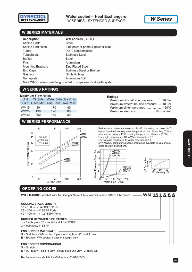
Water cooled - Heat exchangersW SERiES - EXTENDED SURFACE
49
W SerieS PerFormance
20 60 100Oil Viscosity cSt
P C
orre
ctio
n F
acto
r
123
5
10
20
Wat
er P
ress
ure
Dro
p kP
a
0 100 20050Water Flow L/min
150
15
WM151WM251WM401
WM402
WM152WM252
5
10
20
30
HE
AT R
EM
OV
ED
(kW
)
40
50
20 100 200
20 100 200
50
50
Oil Flow L/min
WM401WM402
WM251WM252
WM151WM152
Oil Δ P= 0.5 Bar= 1.0 Bar
Performance curves are based on iSO 68 oil entering the cooler 40°C higher than the incoming water temperature used for cooling. This is also referred to as a 40°C entering temperature difference (ETD). For single pass models Oil to Water flow ratio is 1:1For two pass models Oil to Water flow ratio is 2:1.DYNACOOL computer selection program is available to size units at other operating conditions.
Description Wm coolers (BlUe) Shell & Ports Steel Shell & Port finish Zinc powder prime & powder coat Tubes 90/10 Copper/Nickel Tubesheets Stainless Steel Baffles Steel Fins Aluminium Mounting Brackets Zinc Plated Steel End Caps Stainless Steel or Bronze Gaskets Nitrile Rubber Nameplate Aluminium Foil Note:WM Coolers must be grounded to ships electrical earth system.
W SerieS materialS
W SerieS ratinGSMaximum Flow Rates Unit Oil Side Water Side Litres/min. Size Litres/Min. One Pass Two Pass WM15 80 170 80 WM25 130 170 80 WM40 200 170 80
ratings Maximum oil/shell side pressure .......... 26 Bar Maximum water/tube side pressure...... 10 Bar Maximum oil temperature ......................150°C Maximum viscosity ...................... 80cSt actual
Wm 15 1 S S SWm = marine - 4” Shell with 1/4” Copper Nickel tubes, aluminium fins, 316SS tube sheet.
coolinG StacK lenGtH15 = 150mm - 3/4” BSPP Ports25 = 250mm - 1” BSPP Ports40 = 400mm - 1 1/2” BSPP Ports
nUmBer oF Water SiDe PaSSeS1 = Single pass, 2” hose tail and 1 1/4” BSPP2 = Two pass, 1” BSPP
enD Bonnet materialS S = Stainless - WM cooler. 1 pass in straight or 90° and 2 pass.B = Bronze - WM cooler. 1 pass in straight only.
enD Bonnet comBinationSS = Straight.n = 90° Elbow - SS316 only - single pass unit only - 2” hose tail.
Replacement anode kits for WM series -73/01/05965.
orDerinG coDeS
W Series
Water co
oleD

Water cooled - Heat exchangersW SERiES - DiMENSiONS W Series
Without bypass water flow less than 250 L/m With bypass water flow exceeds 250 L/m
LP
72 WATERPORTS
1 1/4" BSPP FEMALE AND2" HOSE TAIL MALE
OILPORTS "H"
A
769.5 Holes
76
EWater
OIL
OILWater
P
L 52P
WATERPORTS
1" BSPP FEMALE
OIL
OIL
90Deg End Bonnet may be rotated to allow hose to be connected from any angle
Water OUTWater IN
DY N A C O O L M W
42060
BTube field length
60
DYN
AC
OO
LM
W
01
630
D YN AC
OO
LM
W06046
35(hose)
70
101
101
1/8" BSPDrain PlugBoth ends
L
72
A
E
1/8" BSPDrain Plug
May be field positioned around 360 deg to suit application.
27(hose)
27
2"(51)hose tail only
WATER PORT
C Adjustable
BTube field length
C Adjustable
126
2"(51)hose
9.5 Holes45 58
88
DimenSionS - W SerieS 2 PaSS
DIMENSIONS - W SERIES 90° END BONNET
COMMON DIMENSIONS Single Pass Models 90° (Both ends) Two Pass Models Weight model a B c e H* l P l^ P l P kg Wm15 75 172 76 148 3/4” Wm151 291 108 348 136 Wm152 275 106 5 Wm25 125 272 190 148 1” Wm251 391 133 448 161 Wm252 375 131 6 Wm40 200 422 288 154 1 1/2” Wm401 542 171 598 199 Wm402 525 169 9
* All ports are BSPP female pipe thread to iSO 228/1G Tolerance + 3mm ^ Overall length for units that have 1x90° and 1xstraight bonnet is L - 28mm. Dimension C is factory preset. Mounting feet location may be adjusted to suit your application. Units may also be rotated and clamped allowing mounting in various positions e.g. -floor, wall or ceiling mounting.
DimenSionS - W SerieS 1 PaSS
50
Wat
er c
oo
leD
Wm cooler - tranSmiSSion coolinG inStallation

ratings Maximum oil (shell) side pressure ............10 Bar Maximum water (tube) side pressure .......10 Bar Maximum temperature..............................145°C
Maximum Flow Rates Unit Size Shell Side l/min Tube Side l/min WS151 80 80 WS301 60 80
51
Water cooled - marine oil Heat exchangersSEN-DURE
PerFormance
20 40 60 80 100 120Oil Viscosity cSt
DP
Cor
rect
ion
Fac
tor
1
2
3
5
10
20
Wat
er P
ress
ure
Dro
p kP
a
0 10050Water Flow L/min
15 WS151
WS301
2
3
HEA
T R
EMO
VED
(kW
)
4
5
10
20 100
20 100
50
50
Oil Flow L/min
Oil DP= 0.5 Bar= 1.0 Bar= 2.0 Bar
WS151BSS
WS301BSS
Performance curves are based on iSO 68 oil entering the cooler 40°C higher than the in-coming water temperature used for cooling. This is also referred to as a 40°C entering temperature difference (ETD). DYNACOOL computer selection program is available to size units at other operating conditions.
222 (8.75")
155.6 (6.125")102 (4")27
(1.063")
54(2.125")
1/2" BSPP
1/8" NPTF(DRAIN)
1/2" BSPP
54(2.125")
1" BSPP
1" BSPP
375 (14.75")
308 (12.125")254 (10")27
(1.063")
WaterOIL
OILWater
Water OIL
OILWater
1/8" NPTF(DRAIN)
materialsShell............................ Copper Tubes .......................... Copper/NickelTubesheets ................. Copper/Nickel End Caps .................... BronzeNameplate .................. Aluminium
Anode available. Part No. WSanoDe 1/8nPt
tecHnical SPeciFicationS
DimenSionS - WS301BBS WEIGHT 2.1KG
DimenSionS - WS151BBS WEIGHT 1.6KG
Anode available. Part No. WSanoDe 1/8nPt
Anode available. Part No. WSanoDe 1/8nPt
All dimensions in mm unless noted otherwise 0-50 are ± 1. 50-1500 are ± 3.
Water co
oleD

temperature ratings. Temperature limitation for standard pumps is 150˚C with Buna N seals. For higher temperatures a modified standard pump with wider running clearances and Viton, Teflon, Graphoil or Kalraz seals are available.
For Extra Hard, Hatrided iron Pumps and Corrosion Resistant Pumps in SS or bronze, contact our sales office.
inPUt SHaFt raDial loaDinGAll of the pump configurations shown below are for direct coupling applications. Where belt or chain drive is used, a special pump with overhung load adapter must be used. Consult sales office for stock options.
ViScoSitY VerSeS FloW rate anD PUmP SPeeDWith the Haight range of rotary gear pumps there is a direct relationship between fluid viscosity and allowable pump speed. Consult table below. The table is based on the use of oil with low levels of abrasive inclusions. Where fluids with high levels of abrasives and/or low levels of lubricity are to be pumped, please consult our sales engineers. During start up operations for brief peak periods, a 12% increase in viscosity is acceptable.
rotation VerSeS oil FloWRelief valve type pumps as shown are rigged for clockwise rotation when viewed from shaft end of pump. Pressure port will be A and suction port B. If anti clockwise rotation is required, invert pressure relief assembly and place it in left side of pump. Port B will then become pressure port and port A the suction port. Non relief valve pumps can be run in either direction as delivered. Seal venting is required for this option.
52
Series U - Universal PumpsThe Universal Pump Design combines the innovation of the Universeal shaft seal, the rugged simplicity of Haight’s proven “gear within gear” internal gear configuration, with the flexibility of a bolt-on, integral Relief Valve assembly. This combination of pump features of-fers pump users unsurpassed flexibility to adapt their pumps to changing system requirements. Universal Relief valve - can be added at any time. Can be used for either suction or return. “Gear within Gear” internal design - since 1937 this design has demonstrated it’s effectiveness in a broad range of applications. Universeal shaft seal - the pump can easily be converted from lip to mechanical or packed gland without disconnecting the piping.
Superior High Viscosity rotary Gear Pumping FeaturesInput drive at the inner gear provides a built in gear reduction which means less cavitation at standard motor input speeds. The inner gear drive also permits a bearing to be provided on either side of the drive shaft and also provides a balanced rotor. These features make the Haight Pump superior for high viscosity pumping. The same features also offer increased life through lower rotor surface speeds and better bearing support Most other rotary gear pumps have input drive at the rotor which increases risk of cavitation, rotor wear, rotor side load and higher bearing loads.
Pumps that Perform
rotary Gear Positive Displacement PumpsU - SERiES
Selection inFormation - StanDarD PUmPS
Max Viscosity Pump cSt Speed RPM
22000 100 5500 250 2500 500 1750 720 to 850 1100 960 to 1150 850 1300 to 1550 650 1750 500 to 25 1800
For pumping high viscosity mineral oils or vegetable oils. The standard models feature cast iron casing and cover components, steel shaft and pinion gear, high tensile iron rotor, self lubrication iron or bronze bearings and Buna-N lip seals. As a general rule, the Cast iron pump will handle most liquids which have a reasonable level of lubricity providing that the liquid is compatible with ferrous components and shaft seal. These models are usually all available from Australian inventory with or without relief valves.
Pressure ratings. Pressure rating for standard Buna-N shaft seals is 5.2 BAR for liquids less than 20 cSt and 7 BAR for liquids of higher viscosity not exceeding 1000 cSt. It is normal practice for lip seals to weep a small amount of liquid during operation. For pressures above 7 BAR, special mechanical seals are recommended. Maximum pressure with mechanical seal is 17 BAR.
*Input power figures are based on use with oil at 50 PSI (350 kPa) pres-sure and suction at 5 ins HG. When viscosity exceeds the 430 cSt stated above, contact our sales office for revised power requirements.
PUmP DiSPlacement Per reV inPUt PoWer kW* PUMP CC PER Flow @ Power @ Power @ SIZE REV 1500 RPM 1500 RPM 1500 RPM L/min Oil 43 cSt Oil 430 cSt 1 3.41 5 0.13 0.24 3 7.20 11 0.13 0.32 5 10.03 15 0.22 0.48 8 18.17 27 0.37 0.63 10 26.12 39 0.52 1.04 15 34.07 51 0.63 1.38 20 43.53 65 0.89 1.60 24 51.85 78 0.82 1.41 30 68.13 102 1.00 1.75 40 89.70 134 1.50 2.16 80 179.4 268 1.80 5.90
# Larger Pump sizes are available up to 750 litres per minute
1. Patented Haight Gear and Rotor for more efficient Positive Displacement pumping.
2. Three Tooth Contact for smoother uninterrupted pressure discharge.
3. Extra Deep Meshing of Gears reduces noise and avoids trapping.
4. New “Bolt on” reversible relief valve system for greater bypass versatility and simple field conversion 3
45
81 2
67
oil
PUm
PS a
nDPU
mP
PacK
aGeS
As seen from non-shaft end
5. Pipe Plug type auxiliary port for tank return relief or for extra circuit installations.
6. Top quality ferrous metal bodies are stand-ard with Gramix iron bearings.
New “UniverSeal” design allows for sim-ple and quick seal replacement or change to an alternative shaft seal type.

28
O 101.6 (4.000")PILOT
146.05 483353
O 13 Holes2 Places
12
rotary Gear Positive Displacement PumpsU - SERiES MOUNTiNG OPTiONS
53
HaiGHt PUmP SiZeS 10U, 15U, 20U, 24U, 30U anD 40U WitH oPtional Foot BracKetS
HaiGHt PUmP SiZeS 1U, 3U, 5U, 8U WitH oPtional Foot BracKetS
*Weights are for pumps with relief valve fitted.PORTS C & D . These ports can be supplied on all sizes of relief valve type pumps. They are auxiliary ports for pressure gauges, vacuum gauges, or for secondary relief valves. The auxiliary pressure port is always the one at the opposite end to the relief valve adjustment screw. On above drawing the auxiliary pressure port is C.
Bracket Centre Height part number X
90/40080F 80 90/40090F 90 90/40100F 100 90/40112F 112 90/40132F 132
Dim ‘X’ = motor frame size
Optional Foot brackets for Pumps10U, 15U, 20U, 24U, 30U, 40U
Optional Foot Bracketsfor Pumps 1U, 3U, 5U & 8U
Bracket Centre Height part number X
90/08071F 71 90/08080F 80
Dim ‘X’ = motor frame size
Larger Capacity Pumps Available -- Consult Factory
Pump Ports A & B Ports C & D G J with J w/o K L “S” Shaft Ø WT-kg* R.V. R.V. 10U 1” NPT 1” NPT 157 103 57 178 70 15.87 (5/8” x 0.187” KEY) 13 15U-20U 1 1/4” NPT 1” NPT 157 103 57 178 70 15.87 (5/8” x 0.187” KEY) 14 24U-30U-40U 1 1/2” NPT 1” NPT 169 103 57 187 76 22.22 (7/8” x 0.187” KEY) 15
All dimensions in mm unless noted otherwise 0-50 are ± 1. 50-1500 are ± 3.
SAE B FlangePump Sizes 10U, 15U, 20U, 24U, 30U & 40U
Kit Part No. - 90/04025 (Flange + Bolts)Flange Part No. - 56/03/04023
SAE A FlangePump Sizes 1U, 3U, 5U, 8U
Part No - 56/03/06033
*Weights are for relief valve pumps
Pump size E F J WT kg*
1, 3, 5 130 85 95 4.5 8 151 83 103 5
U SerieS PUmP WitH Sae 2 Hole HYDraUlic interFacinG
Pumps that Perform
5880
13
5075
9 mm Holes4 Places
2722
27F
E
38X
J
5
PORT "B"3/4" NPT
PORT "A"3/4" NPT
PORT"D"
1/2" NPT
PORT"C"
1/2" NPT Relief ValveAdjustment
121
Pump ShaftØ12.7 (1/2")
Key 3.17 (1/8")
Ø41.27 Spigot
22
106.3 3018.6
36
6.3582.5 (3.25")PILOT
PORT "C"
PORT "A" PORT "B"
ROTATION
K
198174
8642 44 48
G
X
LJ
1027513.5
28
S
Relief ValveAdjustment
4 Bolts 1/2" 13 TPI UNCOn 3.500" Square PatternAround 3.000" Pilot BossOn Pump
O 12.7 Holes4 Places
oil PUm
PS anDPUm
P PacKaGeS

orDerinG coDe 90H B / 10 U 6P 220 Part Number
HaiGHt PUmP aSSemBlY 90H PUmP/motor Bell housing B connection Bedplate
PUmP SiZe 01 03 05 08 10 15 20 30 40
relieF ValVe With relief UR Without relief U
electric motor SPeeD 4P 6P 8P 1440 960 720
electric motor PoWer 0.37kW 037 0.55kW 055 0.75kW 075 1.5kW 150 etcSPecial FeatUreS (eg S = single phase)
note: not all combinations available, check with sales office
54 55
Haight pump and electric motor packages come complete with pump, electric motor, base plate, flexible shaft coupling and bell housing. Haight pump and electric motor packages are available with 4 pole 415 volt AC electric motors ranging from 0.55 kW to 4 kW. Units with 6 or 8 pole motors can also be supplied on request as well as single phase 4 or 6 pole motors in sizes to 2.2kW.The standard motor rating is IP55 class F insulation. Motors with special specifications can also be supplied (eg flameproof).Electric motor dimensions vary depending on brand. To estab-lish the final dimensions of the assembly use measurement “H” which is the position of the foot mounting bolt at shaft end of the electric motor. Use a manufacturer’s drawing of the selected electric motor to establish final dimensions. CAD DXF drawing available on request.
motor PoWer (kW) & amPS BY Frame SiZe FRAME* kW at 4 POLE AMPS kW at 6 POLE AMPS 80 0.55 to 0.75 2.0 0.37 to 0.55 1.90 90 1.10 3.0 0.75 2.30 90L 1.50 3.3 1.10 3.00 100 2.20 to 3.00 5.8 1.50 3.80 112 4.00 8.0 2.20 5.30
*To AS1360
Shown with relief valve pump (UR model)Optional higher pressure springs available.Also available without relief valve (U model).
USES AN 80 OR 90 FRAME MOTOR DEPENDENT UPON PUMP SIZE & MOTOR SPEED
All dimensions in mm unless noted otherwise 0-50 are ± 1. 50-1500 are ± 3.
rotary Gear Positive Displacement PumpsHAiGHT PUMP AND ELECTRiC MOTOR PACKAGES
motor anD PUmP PacKaGeS - SiZe 1 tHroUGH 8
Pumps that Perform
oil
PUm
PS a
nDPU
mP
PacK
aGeS
25 2002504 MOUNTING HOLES
Ø 11 TO SUIT M10 BOLTS
110
INLET & OUTLETPORTS 3/4" NPT
528 *
206 16712
85 *12
30
5.1
RELIEF VALVE PORTS1/2" NPT
113
131
* DEPENDS UPON MOTOR BRAND
ALUMINIUMBELL HOUSING

54 55
motor anD PUmP PacKaGeS - SiZe 10 tHroUGH 80
Pump Ports A & B Ports C K
10UR 1” NPT 1” NPT 178 15UR-20UR 1 1/4” NPT 1” NPT 178 24UR -30UR 1 1/2” NPT 1” NPT 187 40UR 1 1/2” NPT 1” NPT 187 80UR 2” NPT - 203
Sizes 10 through 40 F G H X# Y Z 80 Motor Frame 206 230 50 213 110 127 90 Motor Frame 206 230 50 223 120 127 100 Motor Frame 236 260 48 233 130 139 112 Motor Frame 236 260 48 245 142 139 112 Motor Frame 236 260 48 309 142 139
RELIEF VALVEADJUSTMENT
BED HOLES 200250
4 HOLESO11
PORT C
PORT "A"
PORT WIDTH K
PORT "B"
X#
Y
G
Z
F
30
H
IN OUT
Aluminium
All dimensions in mm unless noted otherwise 0-50 are ± 1. 50-1500 are ± 3.
iN ORDER TO CONSTANTLY iMPROVE OUR PRODUCT WE RESERVE THE RiGHT TO MAKE CHANGES WiTHOUT NOTiCE
oil PUm
PS anDPUm
P PacKaGeS
Shown with relief valve pump (UR model)Optional higher pressure springs available.Also available without relief valve (U model).
Pumps that Perform
rotary Gear Positive Displacement PumpsHAiGHT PUMP AND ELECTRiC MOTOR PACKAGES

aPPlicationThe BMT thermo switch is designed for controlling electric motors. The switch is suitable for use in either 240 Vac or 12/24 Vdc. The switch can be used in 415Vac 3 phase by connecting to the relay side of a three phase contactor.
The thermo switch uses a reliable “snap” action bime-tallic disk type switch, which is sealed for life inside a brass bulb well. The switch contacts are Normally Open and silver plated for long life when operated in the range specified. The cable connector is to the PG09 Din 43650 std. The switch bulb has a threaded ½” BSPP male connection and a Dowty seal.
Switches are fixed temperature (not adjustable).
SpecificationsSwitch rating -10A/250 Vac - 3A/ 12 or 24 Vdc (use relay for higher current draw)Max Pressure - 20 barMax Differential - 16° CTemperatureMax. temp. - 120° CProtection - iP65Plug Connector - PG09, DiN 43650Material Body - Brass Contacts - SilverThread - ½” BSPP
56 57
Heat exchanger accessoriesTEMPERATURE SWiTCH - SERiES BMT
All dimensions in mm unless noted otherwise 0-50 are ± 1. 50-1500 are ± 3.
acce
SSo
rieS
65
49
06
106
Sq. 30 A/F
1/2" BSPP
PG09 Cable Connector
Dowty Washer
DYNACOOL AiR COOLED HEAT EXCHANGERAuxiliary Port Details for thermoswitch mounting
Heat Exchanger Auxiliary Reducer Model Port Size Bush (RYCO) TM20, TM40 1/2” BSPP None Req VC2 1/2” BSPP None Req VC4,5,6,7 & 8 3/4” BSPP S102-1208 DC31 & DC32 1 1/4” BSPP S102-2012 & S102-1208 DC32S 3/4” BSPP S102-1208 DC33 & DC35 3/4” BSPP S102-1208Above reducers are available for purchase from OEM Dynamics.
BaSic SWitcH order code Closing Temperature 17/BMT45WNO 45°C 17/BMT55WNO 55°C 17/BMT65WNO 65°C

aPPlicationThe thermostatic control circuit is designed for use with 3 phase electric motors primarily switching the fan motor on heat exchangers, other uses include switching control of small pump units. The control circuit can be switched by any 240V thermoswitch or other similar switching device.
FeatUreSThe control switch on the junction box is a three position switch with ON OFF and AUTO positions. When switched to the AUTO position the electric motor is controlled by the switching signal from the external thermoswitch (Supplied with kit units). The control circuit features high quality compo-nents, robust switch and contactor relay, and wafer type terminals mounted on DIN rail. The junction box has holes predrilled for cable glands and is supplied with 0.5 metres of pre wired cable for the electric motor.
56 57
Heat exchanger accessories3 PHASE THERMOSTATiC CONTROL
Heat exchanger accessoriesLOW VOLTAGE WiRiNG KiTS - 12V AND 24V DC
General DeScriPtion Wiring harness kits are available for all Versacool & Dynacool low voltage 12V/ 24V DC fan cooler models. Kits include a switch, fuse, fuse holder, port adaptor, relay, wiring and fitting instructions.
All dimensions in mm unless noted otherwise 0-50 are ± 1. 50-1500 are ± 3.
acceSSorieS
DANGER415 VOLTS
ISOLATE SUPPLYBEFORE OPENING
ON OFF AUTO
A
119 25 73
162
75
118
VIEW AMOUNTING DETAILS
2 HOLESØ16 FORCABLESCAPPED
4 W IRE CABLE0.5m LONG TO
ELECT. MTR
4 MOUNTING HOLES Ø4
TO THERMOSWITCHNORMALLY OPENCLOSE ON HIGH
TEMP
415V 3PHPOWER IN
Wiring Harnesses to suit temp Setting Part no. Description
tm20 & 40, Vc2-6 single fan coolers12 Volt Kits55°C 039.8.06172 VC2-6 12V Wiring Kit65°C 039.8.06173 VC2-6 12V Wiring Kit24 Volt Kits55°C 039.8.06142 VC2-6 24V Wiring Kit65°C 039.8.06143 VC2-6 24V Wiring Kit
VC7 & 8 twin fan coolers12 Volt Kits55°C 039.8.06371 VC7-8 Twin fan 12V Wiring Kit65°C 039.8.06372 VC7-8 Twin fan 12V Wiring Kit24 Volt Kits55°C 039.8.06369 VC7-8 Twin fan 24V Wiring Kit65°C 039.8.06370 VC7-8 Twin fan 24V Wiring Kit
Other temperature settings are available on request.
KIT with SWITCH and JUNCTION BOX
order code Closing Temperature
17/JB/BMT/45 46°C 17/JB/BMT/55 55°C 17/JB/BMT/65 65°C
BMT Thermoswitch
Dowty Washer
Pipe Thread Adaptor
3/4" BSPP
PG09 Cable Gland
Dowty Washer
49
9215Sq 30 A/F
Hex 35 A/F

58 59
Heat exchanger accessoriesVERSACOOL ACCESSORiES
B + 60130
A1 + 54Slots 16 x 10
Increases E By 3 MM14 1461
20
BA1 + 4
Slots 16 x 10
295
150
26515
moBile BaSe Kit UniVerSal BaSe Kit
Ordering detailsModel VC2 Part no. 039.8.04590Models VC4 thru VC8 Part no. 039.8.04563
Ordering detailsModels VC2 thru VC8 Part no. 039.8.04465
Weight 1.1kg Weight 0.76kg
Recommended for mounting of Versacool units in areas where they may be subjected to harmful vibration
These antivibration mounting feet are used to protect the cooler from harmful vibration and to reduce noise associated with vibration. The antivibration mounts can be used in conjunction with the universal base kit or mobile base kits.
antiViBration moUntinGS
28
B - 30B
77
B + 30Typical installation to basic cooler
Ordering detailsSet of 4 antivibration feet + mounting screws Part no. 039.8.05528
These antivibration mounts can be retrofitted to existing cooler installations due to the mounts ‘inline’ construction. Recommended for mounting of Versacool units in areas where they may be subjected to harmful vibration
These antivibration mounting feet are used to protect the cooler from harmful vibration and to reduce noise associated with vibration.
Ordering detailsSet of 4 retrofit feet + mounting screws Part no. 039.8.05537
retroFit tYPe
All dimensions in mm unless noted otherwise 0-50 are ± 1. 50-1500 are ± 3.
acce
SSo
rieS
DeBriS Screen
A debris screen can be fitted to our range of Versacool & Dynacool range of air cooled heat exchangers. On the Dynacool range, the debris screen replaces the standard wire mesh core guard.
The debris screen consists of an aluminium frame with SS mesh. Finish is polyester powder coat “black”.
The debris screen can be removed for cleaning without removing the heat exchanger core element.
Contact our sales office for further details.

58 59
Heat exchanger accessoriesTHERMAL BYPASS ASSEMBLY
This thermal bypass valve is ideally suited for hydro-static drive circuits which require fast warm-up, control-led fluid temperature, and low return line back pressure. When installed in the return line of a hydraulic circuit that employs an oil cooler, this device will modulate fluid temperature by either shifting return line flow through the cooler, or bypassing directly to the reservoir. In ad-dition, a built-in pressure relief function automatically relieves excess pressure to the reservoir should the cooler become restricted and resultant pressure drop become too high for the cooler circuit.
Part no Shift temperature Part no Shift temperature 65/65654 38°C (100°F) 65/65656 60°C (140°F) 65/65655 49°C (120°F) 65/65657 71°C (160°F)
DimenSionS - thermal Bypass PreSSUre DroP
moDe examPleS
Based on Mobile DTE 26 oilNote: Pressure drop shown is added to relief valve crack pressure for total pressure drop.
orDerinG inFormation
Graphic SymbolCoolerReservoir
INLET
A A
INLET
10.7 (0.42" Dia2 Mounting holes
#16 SAE1 5/16-12UN-2B"O" ring Port(3 Places)
Tank Port
Cooler Port(CLR)
VIEW A-A
TANK
72.9(2.87")
47.8(1.88") 66.5
(2.62")137.4(5.41")
89.4(3.52")
0 10 20 30 40 50 60
80
60
40
20
FLOW - GPM
PSID
INLET PORT THRU TANK PORT@ 38C (100F) (300 SUS)
0 10 20 30 40 50 60
16
12
8
4
FLOW - GPM
PSID
INLET PORT THRU COOLER PORT@ 63C (145F) (110 SUS)
0 10 20 30 40 50 60
160
120
80
40
FLOW - GPM
INLET PORT OVERINTEGRAL RELIEF VALVE
@ 77C (170F) (78 SUS)
PSID
All dimensions in mm unless noted otherwise 0-50 are ± 1. 50-1500 are ± 3.
FeatUreS:1. Operating Characteristics: A. Mode #1: At temperatures below the shift temperature oil flows from
inlet to tank port. B. Mode #2: At temperatures between the start of shift & full shift the
flow from the inlet port is divided between the cooler & tank ports. C. Mode #3: At temperatures above the full shift temperature inlet flow
is through cooler port. D. Mode #4: At temperatures above the full shift temperature the excess
pressure is relieved through the tank port.2. Standard Shift Temperatures: 100°F(38°C). 120°F (49°C) 140°F (60°C)
and 160°F (71 °C)3. Full Shift (Cooler Port Open) Temperature: Shift temp plus 25°F (14°C)4. Relief valve setting: 65 psi (4.5 bar). Consult factory for other settings.5. Maximum Operating Pressure: 250 psi (17 bar)6. Proof Pressure: 300 psi (21 bar)7. Minimum Burst Pressure: A. Up to the full shift temperature: 325 psi (22 bar) B. Above the full shift temperature: 600 psi (41 bar)8. Minimum Operating Temperature: -30°F (-34°C)9. Maximum Operating Temperature: Shift temperature plus 75°F (42°C)10. Maximum Flow Rating: 60 gpm (227 i/m)11. Leakage @ 250 psi (17 Bar) and 60 gpm (227 l/min) inlet Flow: A. Cooler Port: 1. 0.5 gpm (2 I/m) maximum up to 5°F (3°C) before shift temp. 2. 1.0 gpm (4 I/m) maximum from 5°F (3°C) before shift to shift. B. Tank Port: 0.10 gpm (0.4 I/m) maximum12. Operating Fluid: Mineral base hydraulic fluids13. Construction: Aluminium die-cast housing.
acceSSorieS

60 61
• No external power source required.
• Opening point setting is simply adjusted by rotating screw on top of valve housing.
• Turning the valve clockwise will decrease the opening temperature.
• Turning the shaft counter clockwise will increase the opening temperature.
• Valves must be adjusted correctly after installation and whilst equipment is operating under normal conditions. Factory does not preset these valves.
• Opening point is adjustable within standard range shown, other ranges also available.
• Closing point is 2-3 degrees below opening point. Differential temp is not adjustable.
• Maximum recommended working pressure is 150 PSI (10 BAR).
• Not suitable for use in saltwater service.
• Bulb well recommended & available upon request as optional extra.
aPPlication: These water modulating valves regulate the flow of water to the heat exchanger. The valve opens when the temperature increases at the sensing bulb. Cooling rate is automatically varied to allow optimum oil temperature to be maintained. Water is conserved by reducing / stopping flow when minimal or no cooling is required
Heat exchanger accessoriesMODULATiNG WATER VALVES AND BULB WELLS
SPeciFicationS
acce
SSo
rieS
Part Number Pipe Opening point Max. Flow Bulb Weight Sensing includes size# temp. range* temp. Max. size approx. Bulb Valve & Sensor (NPT) Min-Max (°C) limit (°C) (L/m) L x dia (mm) (Kg) Number
65/65511 1/2” 24 - 57 93 95 254x17.5 2.0 65/65293 1/2” 46 - 82 93 95 83x17.5 2.0 65/65293S 65/65253 3/4” 24 - 57 93 150 254x17.5 2.7 65/65127 3/4” 46 - 82 93 150 83x17.5 2.7 65/65293S 65/65254 1” 24 - 57 93 200 413x17.5 4.6 65/65128 1” 46 - 82 93 200 153x17.5 4.6 65/65128S 65/65255 1 1/4” 24 - 57 93 280 413x17.5 5.5 65/65146 1 1/4” 46 - 82 93 280 153x17.5 5.5 65/65128S

60 61
Recommended bulb well part numbers are listed below for all of the above valves. Factory recommends the longer bulb well to provide additional protection. # Contact our sales office for larger size valves. * Valve is fully open 20°C above opening point.
oriFice PlUG.All valves are supplied with a drilled & tapped female by-pass hole inside the regulator body. A solid plug is installed in this hole for 100% shut off. Each valve is also supplied with a drilled orifice plug, packed in an envelope for field installation, if continuous minimum flow is required. The 1/2” & 3/4” valves use a plug with a 1.6mm orifice diameter, the 1’ & 1 1/4” valves have a plug with a 2.4mm diameter.
Heat exchanger accessoriesMODULATiNG WATER VALVES AND BULB WELLS
materialS of conStrUction.VALVE - Body ....................3/8”, 1/2” and 3/4” - Cast Brass 1” through 2 1/2” - Cast iron Valve disk.............Buna N Disk holder ...........Brass Valve seat ............Aluminium Bronze Diaphragms .........Nylon Reinforced Buna NCAPiLLARY TUBE ..............Copper in Brass sheathSENSiNG BULB ..................CopperBULB WELL ........................Brass or brass & copper
A
B
C
D
E
F
L
NM
32
1/2" NPT InternalThread
Armoured capillary tube is 1.83 meters longwith outside diameter of 6mm
ExternalThread
Ø21
Ø17SENSING BULB
BULB WELL
1/2" NPT
All dimensions in millimetres. Tolerance +/- 0.5 mm
NOT TO SCALE
All dimensions in mm unless noted otherwise 0-50 are ± 1. 50-1500 are ± 3.
acceSSorieS
A
B
C
D
E
F
L
NM
32
1/2" NPT InternalThread
Armoured capillary tube is 1.83 meters longwith outside diameter of 6mm
ExternalThread
Ø21
Ø17SENSING BULB
BULB WELL
1/2" NPT
ValVe PORTS A B C D E F L Part no. NPT
65/65511 1/2” 83 178 86 47 38 10 254 65/65293 1/2” 83 178 86 47 38 10 83 65/65253 3/4” 90 189 96 52 44 10 254 65/65127 3/4” 90 189 96 52 44 10 83 65/65254 1” 123 259 139 67 51 13 413 65/65128 1” 123 259 139 67 51 13 153 65/65255 1 1/4” 124 269 119 67 60 13 413 65/65146 1 1/4” 124 269 119 67 60 13 153
BUlB Well m N ExternalPart No Thread65/65141 185 160 3/4” BSPP65/65140 115 88-90 3/4” BSPP65/65280 285 260 3/4” NPT65/67438 444 418 3/4” NPT
Approx. weight 0.5kgs

• Flows up to 490 L/min
• Standard Ports 2” NPT (Opt. 1/2”, 3/4”, 1” & 1 1/2”)
• Flanged Ports Optional 3”, 4” & 6”
• Opening Temp range from 21° to 102° C.• Max. Operating Pressure of 8 Bar (115 PSI).
97
248
90 73
By-passport
Heat exchanger port
Inlet Port
B
HeatSource
Pump
AB
C
DYNACOOLHeat Exchanger
HeatSource
Pump
AB
C
C
A
2” NPT All ports female thread.Warning: 0.5 Bar (7 PSI) ∆P across valve Ports
General Description Three way thermostatic valves use the principle of expanding wax. A self contained power ele-ment activates a stainless steel sliding valve which provides a positive three way action. All temperature settings are factory set. Elements are field replaceable, hence valves can be altered to operate at a different temperature range or refitted with new elements of the same setting.During cold start up, total flow is through the by-pass port. Once the fluid temperature reaches the opening point, the valve begins to open and flow to the heat exchanger supply port begins. As the temperature rises the valve shifts further allowing more flow through the heat exchanger supply port and less to the by-pass port. When the fully shifted tem-perature is reached the valve is fully stroked and all flow is directed to the heat exchanger port.Valves can be used for oil or fresh water serviceHousing - Cast iron (optional steel or bronze)
o-rings - Viton (optional, Buna N)Valve - Alloy steel.applications Three way thermostatic valves may be in-stalled for either “mixing” or “diverting” modes of operation and can be mounted in any plane and with port orientated in any direction.When installing in mixing mode, the valve must be located on the cold side of the application. Hot liquid will be mixed with cooled fluid to discharge liquid at proper temperature. Select a valve with opening point at, or just above, the minimum desired oil operating temperature.For diverting mode, the valve must be installed on the hot side of the application. Cold liquid will be bypassed until the system warms up, then flow is directed to the heat ex-changer. Select a valve with full shift point at, or just below, the maximum desired oil operating temperature.
Code Part Type 66041 Complete valve 67818 Element only
tHree - WaY orDerinG coDeS65/ 66041 / 43/54
Heat exchanger accessoriesTHREE - WAY THERMOSTATiC VALVE
MiXiNG Applications DiVERTiNG Applications
PRESSURE DROP TABLE (Bar) Flow Oil Viscosity (cSt) L/min 255 180 115 85 water 190 0.12 0.12 0.10 0.08 0.07 285 0.24 0.21 0.17 0.15 0.13 380 0.42 0.38 0.33 0.30 0.26 475 - - - - 0.44max. flow (l/min) 405 425 445 465 490
Code Opening Fully Point °C Shifted °C 21/24 21 24 29/41 29 41 38/47 38 47 43/54* 43 54 51/60 51 60 57/66* 57 66 63/71 63 71 66/74 66 74 68/78 68 78 71/79 71 79 74/82 74 82 79/88* 79 88 87/98 87 98 93/102 93 102
* common stocked settings
2” NPT model weights 9 kg
62 63
acce
SSo
rieS
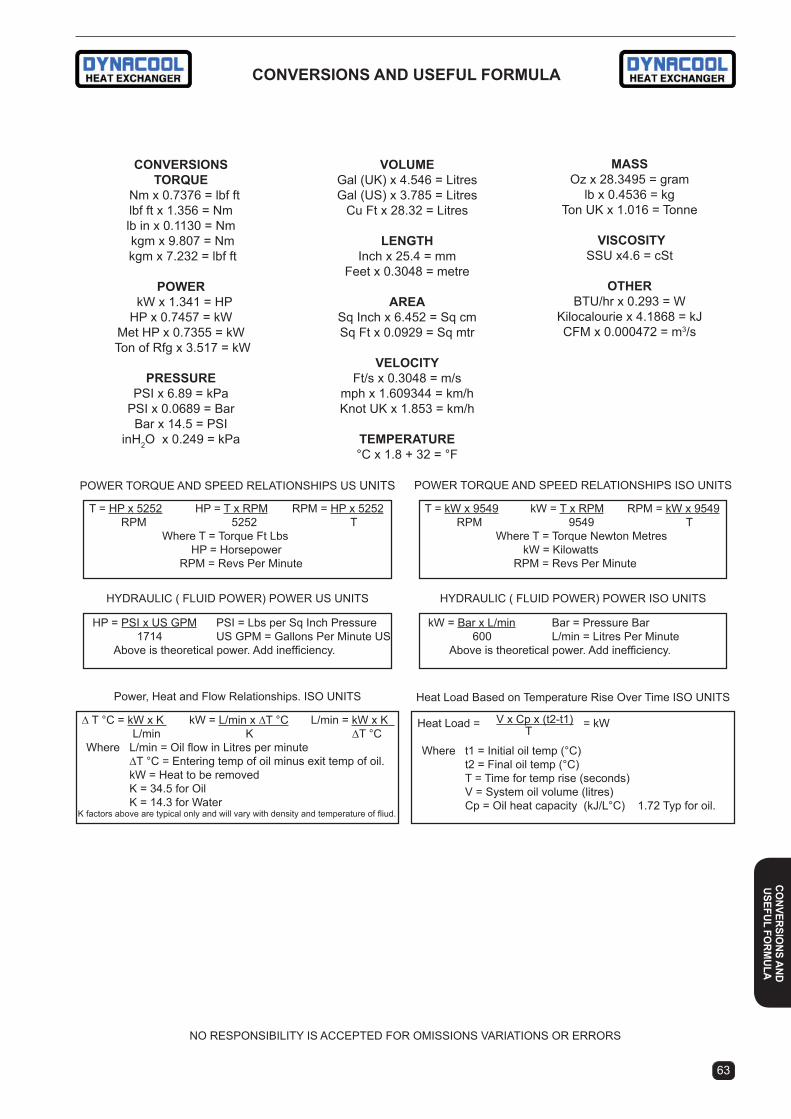
62 63
Heat Load Based on Temperature Rise Over Time iSO UNiTS
Heat Load = = kW
Where t1 = initial oil temp (°C) t2 = Final oil temp (°C) T = Time for temp rise (seconds) V = System oil volume (litres) Cp = Oil heat capacity (kJ/L°C) 1.72 Typ for oil.
V x Cp x (t2-t1)T
∆ T °C = kW x K kW = L/min x ∆T °C L/min = kW x K L/min K ∆T °C Where L/min = Oil flow in Litres per minute ∆T °C = Entering temp of oil minus exit temp of oil. kW = Heat to be removed K = 34.5 for Oil K = 14.3 for Water K factors above are typical only and will vary with density and temperature of fliud.
Power, Heat and Flow Relationships. ISO UNITS
conVerSionStorQUe
Nm x 0.7376 = lbf ftlbf ft x 1.356 = Nmlb in x 0.1130 = Nm kgm x 9.807 = Nm kgm x 7.232 = lbf ft
PoWer kW x 1.341 = HPHP x 0.7457 = kW
Met HP x 0.7355 = kW Ton of Rfg x 3.517 = kW
PreSSUrePSI x 6.89 = kPa
PSI x 0.0689 = BarBar x 14.5 = PSI
inH2O x 0.249 = kPa
POWER TORQUE AND SPEED RELATiONSHiPS iSO UNiTS
HYDRAULiC ( FLUiD POWER) POWER iSO UNiTSHYDRAULiC ( FLUiD POWER) POWER US UNiTS
POWER TORQUE AND SPEED RELATiONSHiPS US UNiTS
T = HP x 5252 HP = T x RPM RPM = HP x 5252 RPM 5252 T Where T = Torque Ft Lbs HP = Horsepower RPM = Revs Per Minute
HP = PSi x US GPM PSi = Lbs per Sq inch Pressure 1714 US GPM = Gallons Per Minute US Above is theoretical power. Add inefficiency.
kW = Bar x L/min Bar = Pressure Bar 600 L/min = Litres Per Minute Above is theoretical power. Add inefficiency.
T = kW x 9549 kW = T x RPM RPM = kW x 9549 RPM 9549 T Where T = Torque Newton Metres kW = Kilowatts RPM = Revs Per Minute
NO RESPONSiBiLiTY iS ACCEPTED FOR OMiSSiONS VARiATiONS OR ERRORS
VolUmeGal (UK) x 4.546 = LitresGal (US) x 3.785 = Litres
Cu Ft x 28.32 = Litres
lenGtHInch x 25.4 = mm
Feet x 0.3048 = metre
areaSq Inch x 6.452 = Sq cmSq Ft x 0.0929 = Sq mtr
VelocitYFt/s x 0.3048 = m/s
mph x 1.609344 = km/hKnot UK x 1.853 = km/h
temPeratUre°C x 1.8 + 32 = °F
maSSOz x 28.3495 = gram
lb x 0.4536 = kgTon UK x 1.016 = Tonne
ViScoSitYSSU x4.6 = cSt
otHerBTU/hr x 0.293 = W
Kilocalourie x 4.1868 = kJCFM x 0.000472 = m3/s
conVerSionS anD USeFUl FormUla
conVerSio
nS anDUSeFUl Fo
rmUla

Determining the level of Heat load in oil circuits.Heat is generated through energy being wasted in the form of inefficiency. Heating in a oil circuit is usually a by-prod-uct of motive power which may be some form of engine or motor or a device such as a brake or clutch which converts rotating energy into heat energy in the oil.
Another source may be by conduction, convection or radia-tion from either direct solar energy or any other external parasite source.
in a hydraulic system, the main energy source is usually the input power entering the hydraulic pump from the engine or motor. Some portion of the input power will be wasted through inefficiency (friction and pressure losses) and will be evident as heat in the oil.
The degree of inefficiency in the circuit may be established by combined analysis of the known efficiency of the circuit components. More frequently it is established by making an estimate based on previous experience with the type of circuit being considered.
Typical hydraulic system circuits range in efficiency from between 80% down to 40% efficient. High efficiency pumps and motors combined with ample plumbing may deliver up to 80% efficiency. Gear pumps with gear motors or gear pumps with gerotor motors may be less than 50% efficient.
The heat load required to be removed from the system will be equal to the total inefficiency in the system, less the existing thermal heat transfer capacity of the system.
So with a circuit estimated to have a power input of 50 kW and an efficiency loss of 30%, there can be expected to be a requirement to cool 15 kW of heat. The components in the circuit may be able to dissipate some heat so the heat load required to be cooled with a heat exchanger will be something less than 15 kW.
Power, Heat and Oil Flow Relationships.in the above example we determined that we need to re-move 15 kW from a circuit. Now what does 15 kW really mean in terms of heat. The following are formulae which can be used with hydraulic mineral oils to provide relationships between power, heat and oil flow.
L/min = Oil flow in Litres per minute.∆T °C = Entering temp of oil minus exit temp of oil. Applying formula 1 to the above example with oil flow at 100 L/min we get the following result.
So we require a constant reduction in temperature of 5.2°C in our oil to dissipate 15 kW for 100 L/min.
15 x 34.5 = 5.2 100
1 ∆T °C = kW x 34.5 L/min
2 kW = L/min x ∆T °C 34.5
3 L/min = kW x 34.5 ∆T °C
oil and air temperature relationships.For the cooling of oil with a air cooled heat exchanger it is obviously necessary to have the air temperature cooler than the entering oil temperature. The temperature differ-ence between the entering oil and the entering cooling air is called the ETD (entering temperature difference).
The larger the ETD the easier it is to cool the oil and by definition the smaller the air cooled heat exchanger will be. For purposes of sizing a suitable heat exchanger, it is usual to set the inlet temperature of the oil at the maximum temperature the system is required to operate at.
Oil temperatures in modern hydraulic systems are preferred to be maintained in the 60°C to 70°C range. The tempera-ture of the cooling air will be the ambient temperature of the air in the locality where the system is to be used.
Selection of the exchanger By Performancein this catalogue, performance shown on graphs is usu-ally expressed in kilowatts per degree °C of entering temperature difference between the oil and the cooling air (kW/°C).So if the ambient temp is 30°C and the oil temp is required to be 60°C, a 15 kW heat dissipation would require a oil cooler capable of 0.5 kW/°C at the required oil flow.
computer model Selection ProgramWe provide complete performance graphs for most models of our air cooled heat exchangers. However, for accurate sizing we recommend the use of our computer model selec-tion program which covers almost all of our standard models of air cooled and water cooled exchangers. The program operates on most PC computers under Windows.
Electronic Drawings Of Heat Exchangers Our computer model selection program now also includes electronic drawings of most models. These drawing are available in DXF format for customer use.
Heat load Based on temperature rise over time Example:
initial oil temp 20°CFinal oil temp 85°CTime for temp rise 35 minutesSystem oil volume 240 litres
Oil heat capacity 1.72 kJ/L°C
Heat Load = = 12.8 kW 240 x 1.72 x (85-20)35 x 60
ProDUct aPPlication
64 65
Pro
DUct
aP
Plic
atio
n

64 65
ProDUct aPPlication
noise levels of air cooled Heat exchangers it is a fact of life that air cooled heat exchangers utilise fans to move air through the cooling matrix. High performance air cooled heat exchangers tend to have dense cooling surfaces and require relatively high levels of air movement under static pressure to achieve performance.
We are now publishing measured noise levels for our air cooled models. The measurement is dB(A) @ 1 metre. For the record, our method of measurement is to take a number of A weighted samples at 1 metre distance from the product at prescribed positions and publish the highest noise level found among the samples. The result approximates that which an inspector will get when he tests on site by survey using AS1217.5.
On any electric air cooled heat exchanger, the noise level will closely relate to the speed of the tips of the fan blades.We publish fan diameters and motor speeds so it is easy for our customers to calculate tip speed. So if you are compar-ing our product with one of our competitor’s products and note his published sound levels are lower than ours then please compare the fan tip speeds.
it is generally the design policy of Dynacool to use smaller diameter more efficient fans than our competitors as well as our SAMS (Superior Air Management System) which reduces fan diameters. Therefore, we claim that relative to size and performance our air cooled heat exchangers generally have lower noise levels than our competitors.
Dynacool have produced Air Cooled Heat Exchanger Packages for oil cooling since 1975. Since that time many hundreds of model variations have been produced. Dy-nacool are acknowledged as leaders in manufacture and industry know how with air cooled heat exchangers for oil cooling. Our products are designed in Australia and our published data is developed through actual test facilities at our Ballina plant in NSW. Our R & D activities include heat transfer design, performance testing and evaluation, pressure drop testing, noise level monitoring and cooling air delivery measurement. Our test facilities enable us to carry out accurate design analysis which results in the constant improvement in our product and provision of accurate data for our publications. Our Dynacool “A” series packages and our recently developed Versacool line command high respect in the heat exchanger market. We also offer a number of other types of air cooled heat exchangers utilis-ing element materials other than aluminium.
air cooled exchanger rigged For Full Status testing
application Warnings - aluminium cooling elementsThe furnace brazed aluminium cooling element has the highest heat transfer efficiency to cost ratio of all oil cooler types. However, care should be taken in making sure that the product is suitable for the application. The following ad-vice applies to all makes of aluminium cooling elements.OVER PRESSURE.Never exceed rated operating pressures. Actual failure may take place at 40% to 60% above rated pressure. On hydraulic circuits under starting conditions in winter with cold oil, pressure drop figures may exceed 10 times those calculated for normal operation. If the hydraulic circuit is capable of pressures exceeding the cooler rating, a failure will occur unless a suitable relief valve is provided to bypass the cooler under these conditions.PRESSURE CYCLING AND SPIKES.Do not install aluminium oil cooler elements in circuits where sudden changes of pressure or oil flow are likely to occur.Eg:- Cylinder circuits or circuits with oscillating valves. Use of this type of cooler in such circuits will result in rupture of the tubes or cracking of tube to header joints. Aluminium is also subject to fatigue failure under high frequency pressure and/or temp cycling. Bypass relief valves or accumulators are not effective against pressure spikes. For these applica-tions refer to BB & HL off-line coolers on page 26. HAZARDOUS ENVIRONMENTS.Aluminium has autogenous sparking capability when im-pacted with iron or steel. For this reason aluminium is not permitted within coal mines in Australia.
DON
OT
USE
INHYDRAULIC CYLINDER CIRCUITS
83/03/05446
ProDUct
aPPlication

PerFormance correction For air DenSitY ( temPeratUre anD eleVation)
ELEVATiON ABOVE SEA LEVEL - FEET (METERS) 0 1000 2000 3000 4000 5000 6000 7000 8000 (305) (610) (914) (1219) (1524) (1829) (2134) (2438)
70 (21.1) 1.00 0.97 0.94 0.91 0.88 0.86 0.83 0.81 0.78 80 (26.7) 0.99 0.96 0.93 0.90 0.87 0.85 0.82 0.80 0.77 90 (32.2) 0.97 0.94 0.91 0.89 0.86 0.83 0.81 0.78 0.76 100 (37.8) 0.96 0.93 0.90 0.87 0.85 0.82 0.80 0.77 0.75 110 (43.3) 0.94 0.91 0.89 0.86 0.83 0.81 0.79 0.76 0.74 120 (48.9) 0.93 0.90 0.88 0.85 0.82 0.80 0.77 0.75 0.73 130 (54.4) 0.92 0.89 0.86 0.84 0.81 0.79 0.76 0.74 0.72 140 (60.0) 0.90 0.88 0.85 0.83 0.80 0.78 0.75 0.73 0.71 150 (65.6) 0.89 0.87 0.84 0.81 0.79 0.77 0.74 0.72 0.70
Heat transfer Performance at High oil ViscosityAir cooled heat exchanger performance and flow capacity will degrade rapidly when oil operating viscosity exceeds 100cSt. Consult the chart inside the back cover to establish operating viscosity of your application. Please check with Dynacool before selecting heat exchangers for use with high viscosity oil.
maintenanceContinued efficient operation of the air cooled heat exchanger is dependent on the heat transfer surface being kept clean. In dirty conditions the core element should be cleaned frequently to remove dust and dirt.. Should the fins be blocked with oil saturated dirt, use a petroleum based cleaning fluid followed by water sprayed from a medium pressure hose. Do not use high pressure hoses for cleaning heat exchangers with aluminium fins.
CAUTION. DO NOT USE CAUSTIC BASED FLUIDS FOR CLEANING ALUMINIUM COOLING ELEMENTS.
installation of air cooled Heat exchangers Plumbing. Unless approved by Dynacool, use flexible rub-ber hoses for connection. The hose size should be the same size or greater than the port thread size. Solid steel pipes are not recommended as they may place excessive loads on the core element. If long hoses are used support them as close to the ports as possible. Threaded connections must be fully sealed. We recommend BSPP o-ring face seal type fittings. Should oil be permitted to leak it may cover the core fins and result in the collection of dust and sludge which reduces cooling performance.note. Do not fit steel fittings to aluminium ports without lubrication as they may bind and damage the port.
Site Location And Environment. Some cooling elements resist corrosive attack better than others, please consult our Engineering Dept. for details of suitability if a corrosive environment exists. For best heat transfer performance, determine the usual direction of air flow at the site and face the cooling element towards the incoming air flow without restriction from objects at air inlet or outlet. The unit should be bolted down through the base slots provided.
Positioning In The Circuit. in hydraulic circuits, the cooler should always be positioned to receive return oil from the circuit. Do not install the cooler in the pressure circuit. Care should be taken to select a oil source which passes oil at a constant flow rate not exceeding maximum recommended. if operating viscosity is likely to exceed 100 cSt consult our sales dept. Unrestricted oil flow path must be maintained from the outlet oil port of the cooler into the oil reservoir.
AIR TEMP.°F (°C)
DC Electric Motor Connections. Ensure the voltage sup-ply matches that of the cooler. Wire the supply to the 2 pin connector with polarity as shown in the diagram provided in the installation instructions. Start the motor and check the direction of fan rotation, a decal shows the correct direction. All fans should pull the cooling air through the cooling ele-ment and discharge it through the fan guard. For Versacool refer to separate instruction forms VC03, VC04 or VC05 if thermostatic controls are to be fitted.
AC Electric Motor Connections. Remove motor junction box and carefully check instructions on wiring which may be displayed inside or outside of junction box. Electric mo-tors of various brands are used , some motors have star connections and others may be wired delta. After wiring has been completed start the motor and check for rotation of the fan. Rotation is usually c/w when viewed from the mo-tor or ac/w when viewed from element. The fan should pull the cooling air through the cooling element and discharge it through the fan guard. All AC electrical wiring should be carried out by a licenced electrician.
Hydraulic Motor Driven Fans. Some units are supplied fitted with Hydraulic fan motors. Hydraulic Motors fitted as fan drives must be piped to permit the fan to rotate freely after the oil flow has been shut off to the motor. Failure to provide such a device may cause the fan to be damaged due to shock loads caused by fan inertia.
66 67
Pro
DUct
aP
Plic
atio
n
ProDUct aPPlication

66 67
PerFormance reQUirementSair cooled Heat exchanger
Company: ____________________________________________ Date:_________________Address: _____________________________________________ State: ________________Phone: _________________________ Fax: ________________________Contact: _____________________________________________ Ref:__________________The following information is required to select an air to oil cooler.1. Heat load: _________________ kW ________________ or hp2. Oil flow rate: _______________ L/min3. Oil type: ___________________ (eg iSO68)4. Maximum desired oil temperature: __________________ °C5. Maximum allowable oil pressure drop: _______________ Bar ____________ or PSi6. Cooling ambient air temperature: °C7. Motor data: 12V - 24V - 240V - 415V - Hyd - no motor.8. Maximum envelope: _________ H __________________ W _____________ D9. Air face velocity (mobile cores only types): ____________ m/s.10. Maximum pressure cooler will be subject to: ___________ Bar. advise if there are any cylinders or other pressure spike producing components in the cooler circuit.
If unsure of the values required the following information will help. Each number below corresponds to the number above.1. Heat load: the heat load may be determined by: a. Hydraulic oil cooling: Assume 30% of the input power will be rejected to heat. If the input power is unknown,
this formula may be used: kW= (system press. Bar) x (L/min flow) x 0.00167 B. Hydrostatic oil cooling: Assume 25% of the input power will be rejected to heat. c. Heat load test: the heat load can be determined by actually measuring the degree temperature rise from a
cold start-up. This temperature rise is the exact amount of heat going into the oil. To run a heat load test, disconnect any heat exchanger in the test loop. Record the increase in oil temperature every 5 minutes. Review the data received, and determine the greatest temperature rise in any 5 minute period.
Heat load = system volume x oil heat capacity x (∆T oil temperature rise) 5 minutes x 60 sec./min
For example - initial oil temp .................. 40°C Final oil temp .................. 50°C Heat Load = 240 x 1.72 x (50-40) = 13.8 kW Time for temp rise ........... 5 minutes 5 x 60 System oil volume .......... 240 litres Oil heat capacity ............ 1.72 kJ/L°C2. Oil flow rate: This is simply the flow rate of the oil circulating through the cooler.3. oil type: Advise oil grade or viscosity vs temperature details4. oil temperature: Oil coolers are typically sized using the maximum desired oil temperatures. Typical temp. ranges are: Hydraulic oil .....................43 - 54°C Hydrostatic drive oil.........54 - 82°C Bearing lube oil................49 - 71°C Lube oil circuits ...............43 - 54°C5 oil pressure drop: Most systems can tolerate a pressure drop through the heat exchanger of 1.5 to 2 Bar. Excessive pressure drop should be avoided. Care should be taken to limit pressure drop to 0.3-0.5 Bar for case drain applications where high back pressure will blow out pump shaft seals.6. cooling air temperature: This is the temperature of the air entering the cooler, also referred to as the ambient air temperature. A normal maximum air temperature is usually between 32°C to 38°C. Care should be taken not to install in confined space as ambient temperature will increase and cause overheating.7. motor data: Most models are available with a wide variety of motors. List as desired. Be sure to indicate any special requirements.8. envelope size: This may be any height, width and depth depending on the application. Allowances should be given so as not to obstruct fan air flow.9. Air face velocity/cooling air flow: Typically oil coolers are sized for 5.5m/s (20 kph) air velocity. When an air volume flow is given in m3/s, it may be converted by: AFV m/s = m3/s face area of core in m2
comPUter Selection ProGramWe provide complete performance graphs for most models of our air cooled heat exchangers. However, for accurate sizing we recommend the use of our computer model selection program which covers almost all of our standard models of air cooled and water cooled exchangers. The program operates on most PC computers under Windows.
iNFORMATiON FOR AiR COOLED OiL COOLER SELECTiON
ProDUct
aPPlication
FAX

68
PerFormance reQUirementSShell & tube Heat exchanger
Company: ____________________________________________ Date:_________________Address: _____________________________________________ State: ________________Phone: _________________________ Fax: ________________________Contact: _____________________________________________ Ref:__________________Type of application: (Seawater / Freshwater) _________________Other: ____________________________
Describe the circuit ____________________________________________________________ __________________________________________________________________________1. Heat Load (kW or Hp) _______________________2. Flow rate (l/min or USGPM) Shell side: _____________ Water/Tube side: ______________3. Oil type (cSt or SSU) _______________________4. Desired Max. inlet fluid temp. (°C or °F) Shell side: _________ Water/Tube side: _________5. Maximum allowable pressure drop (PSI or BAR) Shell side: ______ Water/Tube side: ______6. Are there any circuit components which could cause sudden changes of oil flow eg cylinders or accumulators ___________________________________________________7. What is the power source and how much power is needed to drive the hydraulics or the source of the heat ___________________________________________________________
The heat load may be approximated by:A. Hydraulic oil cooling: Assume 30% of the input horsepower.B. Hydrostatic oil cooling: Assume 25% of the input horsepower.C. Automatic Transmission: Assume 30% of engine horsepower.D. Engine oil cooling: Assume 10% of engine horsepower.The above are only to be considered as guidelines. It is the customers responsibility to provide accurate information in order to select the most appropriate sized heat exchanger.
Pro
DUct
aP
Plic
atio
n
iNFORMATiON FOR WATER COOLED OiL COOLER SELECTiONFAX

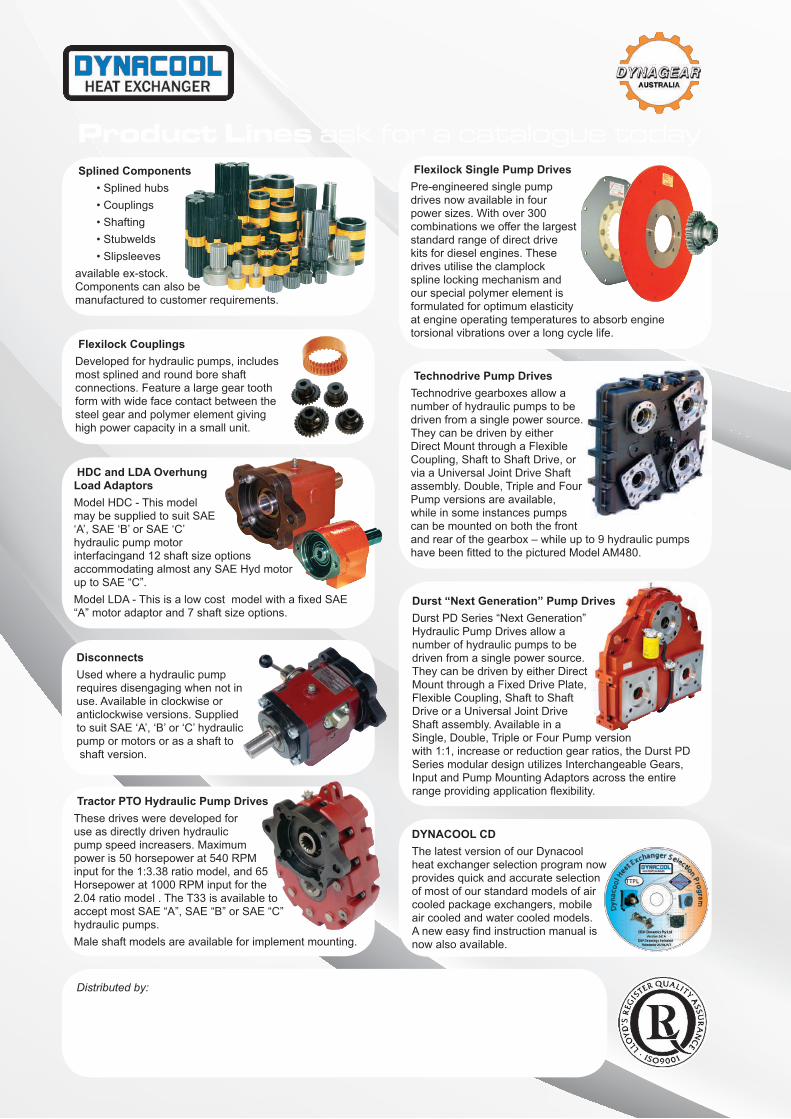
Splined Components
available ex-stock.Components can also bemanufactured to customer requirements.
Flexilock CouplingsDeveloped for hydraulic pumps, includes most splined and round bore shaft connections. Feature a large gear tooth form with wide face contact between the steel gear and polymer element giving high power capacity in a small unit.
Flexilock Single Pump DrivesPre-engineered single pump drives now available in four power sizes. With over 300 combinations we offer the largest standard range of direct drive kits for diesel engines. These drives utilise the clamplock spline locking mechanism and our special polymer element is formulated for optimum elasticity at engine operating temperatures to absorb engine torsional vibrations over a long cycle life.
HDC and LDA OverhungLoad AdaptorsModel HDC - This modelmay be supplied to suit SAE‘A’, SAE ‘B’ or SAE ‘C’hydraulic pump motorinterfacingand 12 shaft size optionsaccommodating almost any SAE Hyd motor
Tractor PTO Hydraulic Pump Drives These drives were developed for use as directly driven hydraulic pump speed increasers. Maximum power is 50 horsepower at 540 RPM
Horsepower at 1000 RPM input for the 2.04 ratio model . The T33 is available to
hydraulic pumps. Male shaft models are available for implement mounting.
DYNACOOL CDThe latest version of our Dynacool heat exchanger selection program now provides quick and accurate selection of most of our standard models of air cooled package exchangers, mobile air cooled and water cooled models.
now also available.
Distributed by:
Product Lines ask for a catalogue today
DisconnectsUsed where a hydraulic pumprequires disengaging when not inuse. Available in clockwise oranticlockwise versions. Suppliedto suit SAE ‘A’, ‘B’ or ‘C’ hydraulicpump or motors or as a shaft to shaft version.
Technodrive Pump DrivesTechnodrive gearboxes allow a number of hydraulic pumps to be driven from a single power source. They can be driven by either Direct Mount through a Flexible Coupling, Shaft to Shaft Drive, or via a Universal Joint Drive Shaft assembly. Double, Triple and Four Pump versions are available, while in some instances pumps can be mounted on both the front and rear of the gearbox – while up to 9 hydraulic pumps
Durst “Next Generation” Pump Drives
Hydraulic Pump Drives allow a number of hydraulic pumps to be driven from a single power source. They can be driven by either Direct Mount through a Fixed Drive Plate, Flexible Coupling, Shaft to Shaft Drive or a Universal Joint DriveShaft assembly. Available in a Single, Double, Triple or Four Pump version with 1:1, increase or reduction gear ratios, the Durst PD Series modular design utilizes Interchangeable Gears, Input and Pump Mounting Adaptors across the entire