Heat exchangers - جامعة نزوى€¦ · · 2013-10-01Heat exchanger types: Heat exchangers...
43
Heat exchangers: The process of heat exchange between two fluids that are at different temperatures and separated by a solid wall occurs in many engineering applications. The device used to implement this exchange is termed a heat exchanger. Heat exchanger types: Heat exchangers are typically classified according to flow arrangement and type of construction. 1
Transcript of Heat exchangers - جامعة نزوى€¦ · · 2013-10-01Heat exchanger types: Heat exchangers...
Heat exchangers:
The process of heat exchange between two fluids thatare at different temperatures and separated by a solidwall occurs in many engineering applications. The deviceused to implement this exchange is termed a heatexchanger.
Heat exchanger types:
Heat exchangers are typically classified according to flowarrangement and type of construction.
1
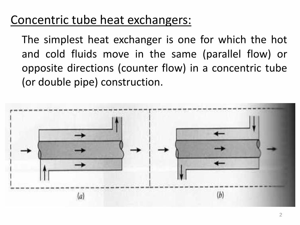
Concentric tube heat exchangers:
The simplest heat exchanger is one for which the hotand cold fluids move in the same (parallel flow) oropposite directions (counter flow) in a concentric tube(or double pipe) construction.
2

Cross flow heat exchangers:
The fluids may move in cross flow (perpendicular toeach other). The finned and un finned tubular heatexchangers are shown in the figure. The twoconfiguration are typically differentiated by the fluidmotion over the tubes as unmixed or mixed.
3
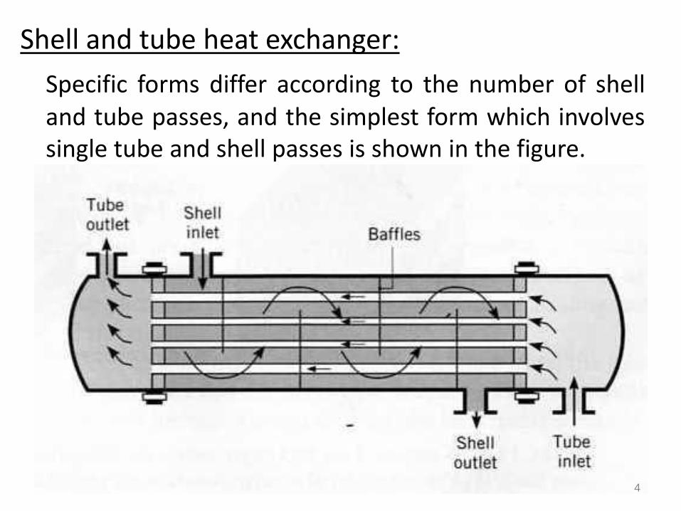
Shell and tube heat exchanger:
Specific forms differ according to the number of shelland tube passes, and the simplest form which involvessingle tube and shell passes is shown in the figure.
4

Baffles are usually installed to increase the convectioncoefficient of the shell side fluid by includingturbulence and a cross flow velocity component.Baffled heat exchangers with one shell pass and twotube passes and with two shell passes and four tubepasses are shown in the figure.
5

6
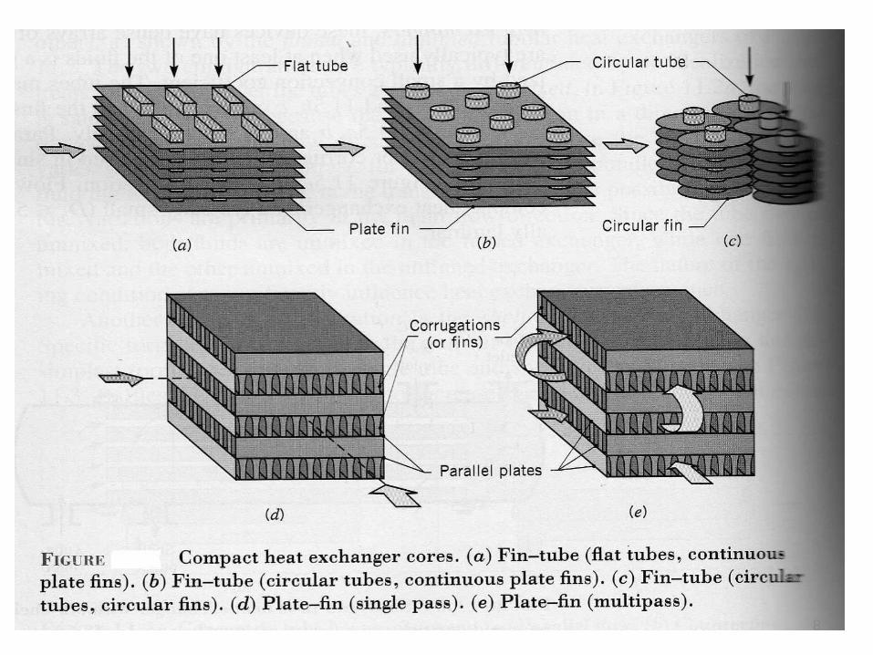
Compact heat exchangers:
A special and important class of heat exchanger isused to achieve a very large heat transfer surface areaper unit volume. Termed compact heat exchangers,these devices have dense arrays of finned tubes orplates and are typically used when at least one of thefluids is a gas and is hence characterized by a smallconvection coefficient.
7
8

Fouling Factors:
After a period of operation the heat-transfer surfacesfor a heat exchanger may become coated with variousdeposits present in the flow systems, or the surfacesmay become corroded as a result of the interactionbetween the fluids and the material used forconstruction of the heat exchanger. In either event,this coating represents an additional resistance to theheat flow, and thus results in decreased performance.
9
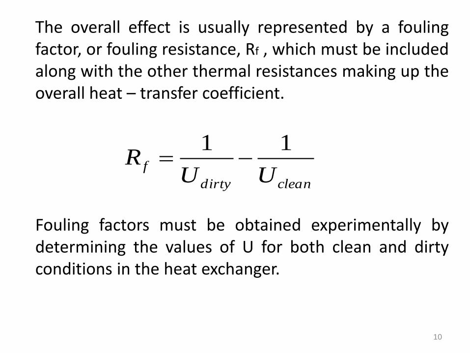
The overall effect is usually represented by a foulingfactor, or fouling resistance, Rf , which must be includedalong with the other thermal resistances making up theoverall heat – transfer coefficient.
Fouling factors must be obtained experimentally bydetermining the values of U for both clean and dirtyconditions in the heat exchanger.
cleandirty
fUU
R11
10
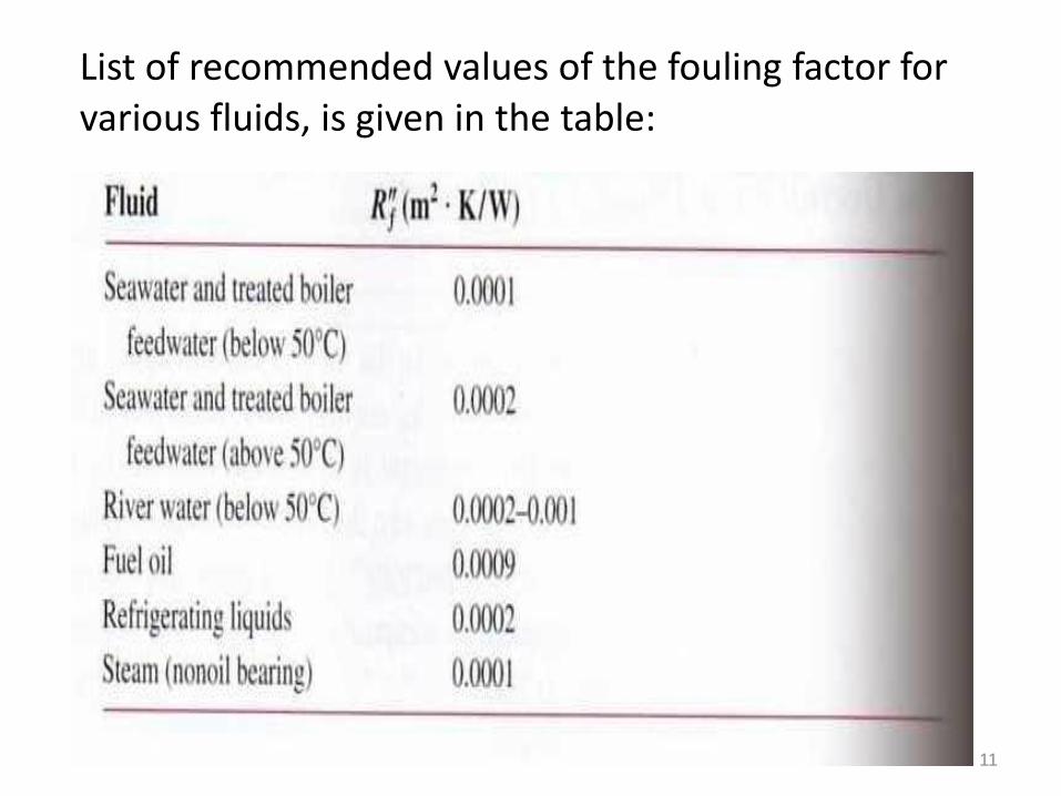
List of recommended values of the fouling factor for various fluids, is given in the table:
11
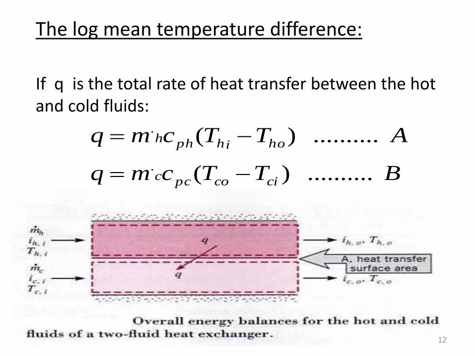
The log mean temperature difference:
If q is the total rate of heat transfer between the hot and cold fluids:
BTTcmq
ATTcmq
cicopcc
hoihphh
.......... )(
.......... )(
.
.
12

Relating q to the temperature difference ∆T between the hot and cold fluids
Since ∆T varies with position in the heat exchanger
Where is an appropriate mean temperature difference.
C .......... ch TTT
D .......... mTUAq
mT
13
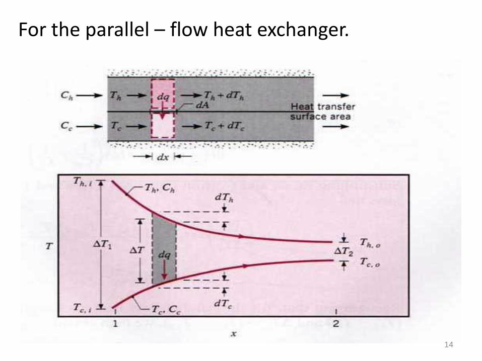
For the parallel – flow heat exchanger.
14
The temperature difference ∆T is initially large butdecays rapidly with increasing x, approaching zeroasymptotically.
The outlet temperature of the cold fluid never exceedsthat of the hot fluid.
The energy balances are subject to the followingassumptions:
15
1. The heat exchanger is insulated from its surroundings, in which case the only heat exchange is between the hot and cold fluids.
2. Axial conduction along the tubes is negligible.
3. Potential and kinetic energy changes are negligible.
4. The fluid specific heats are constant.
5. The overall heat transfer coefficient is constant.
16
Applying the energy balance to the differential element,
Where Ch and Cc are the hot and cold fluid heat capacity rates, respectively.
The heat transfer across the surface area dA may be expressed as:
Where ∆T = Th - Tc is the local temperature difference between the hot and cold fluids.
FdTCdTcmdq
EdTCdTcmdq
cccpcc
hhhphh
..........
..........
.
.
GTdAUdq ..........
17
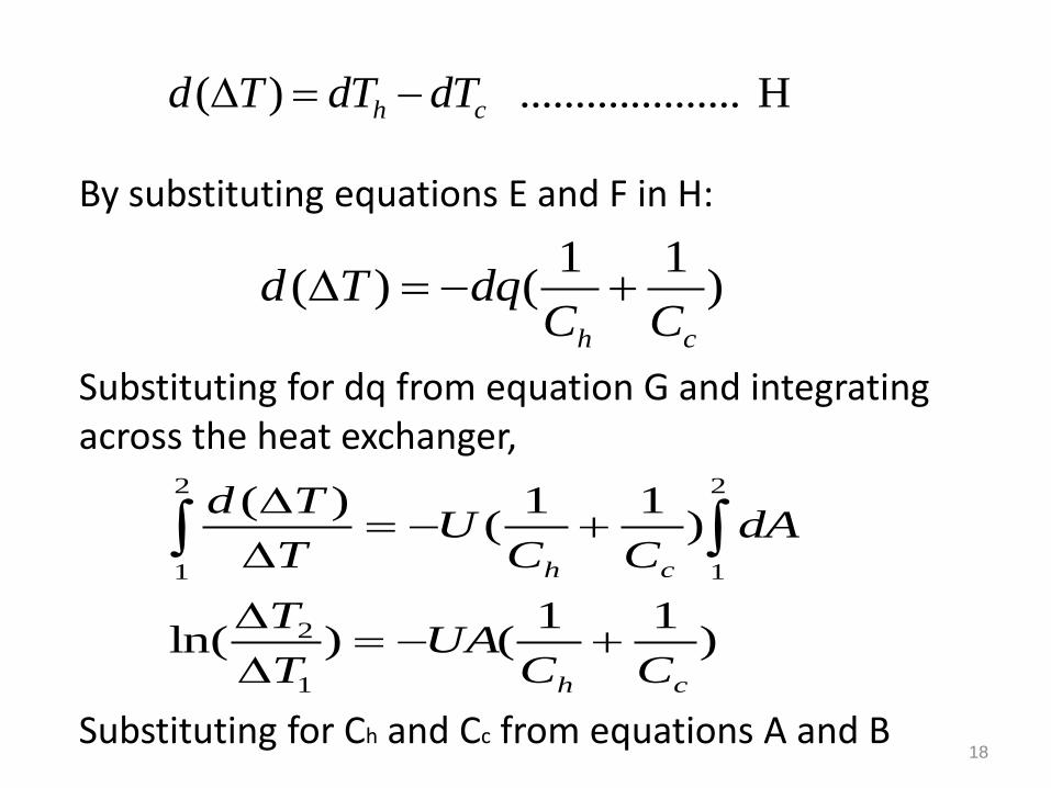
By substituting equations E and F in H:
Substituting for dq from equation G and integrating across the heat exchanger,
Substituting for Ch and Cc from equations A and B
H .................... )( ch dTdTTd
)11
()(ch CC
dqTd
)11
()ln(
)11
()(
1
2
2
1
2
1
ch
ch
CCUA
T
T
dACC
UT
Td
18
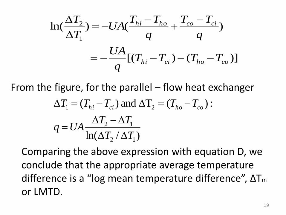
From the figure, for the parallel – flow heat exchanger
Comparing the above expression with equation D, we conclude that the appropriate average temperature difference is a “log mean temperature difference”, ∆Tm
or LMTD.
)]()[(
)()ln(1
2
cohocihi
cicohohi
TTTTq
UA
q
TT
q
TTUA
T
T
)/ln(
:)(T and )(
12
12
21
TT
TTUAq
TTTTT cohocihi
19

Jb .......... TTT
Ja .......... TTT
:exchanger flow - parallel For the
I ..........
)ln()ln(
ho2h22
hi1h11
2
1
21
1
2
12
coc
cic
m
TT
TT
T
T
TT
T
T
TTT
20
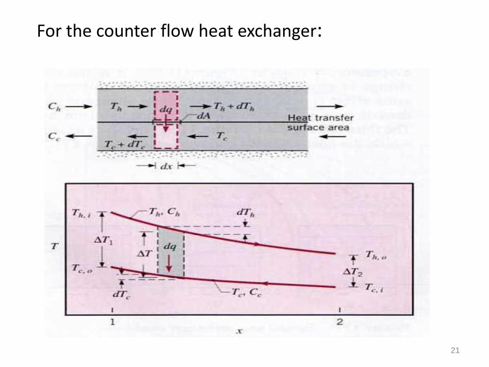
For the counter flow heat exchanger:
21
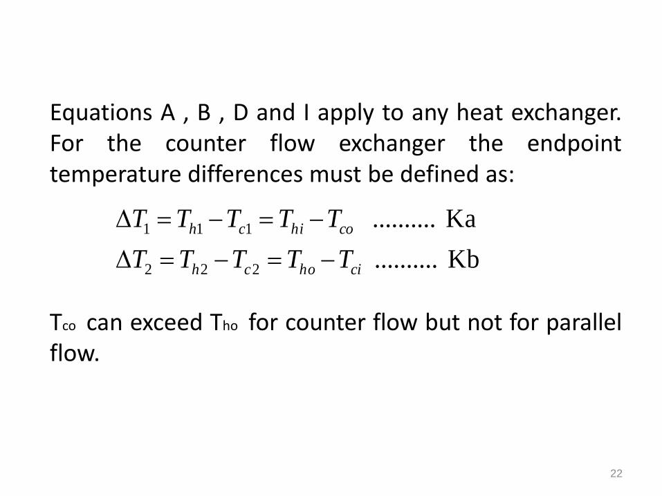
Equations A , B , D and I apply to any heat exchanger.For the counter flow exchanger the endpointtemperature differences must be defined as:
Tco can exceed Tho for counter flow but not for parallelflow.
Kb ..........
Ka ..........
222
111
cihoch
cohich
TTTTT
TTTTT
22
Note that, for the same inlet and outlet temperatures, the log mean temperature difference for counter flow exceeds that for parallel flow,
Hence the surface area required to effect a prescribed heat transfer rate q is smaller for the counter flow than for the parallel-flow arrangement, assuming the same value of U.
PFmCFm TT ,,
23
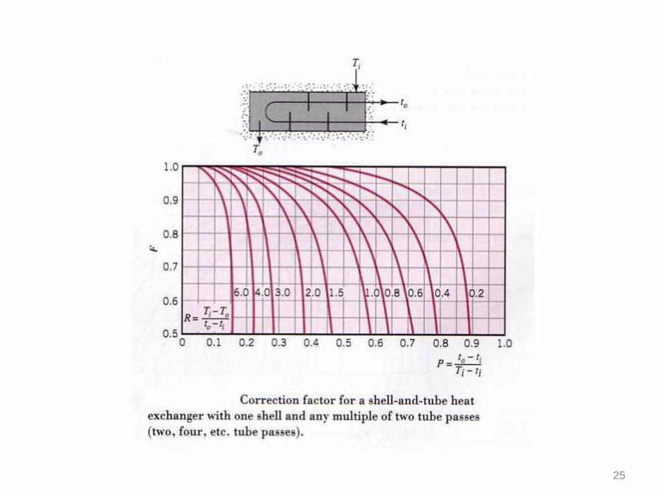
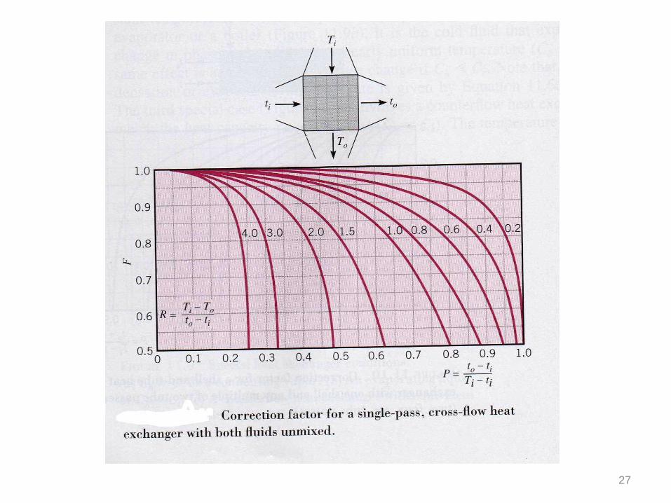
If heat exchanger other than double-pipe type is used,the heat transfer is calculated by using a correctionfactor (F) applied to the LMTD for a counter flowdouble-pipe arrangement with the same hot and coldfluid temperature:
Value of the correction factor F are plotted in thefigures. For several different types of heat exchangers.
24
L ................... mTUAFq
25

26
27

28
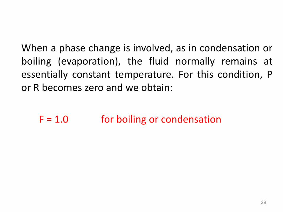
When a phase change is involved, as in condensation orboiling (evaporation), the fluid normally remains atessentially constant temperature. For this condition, Por R becomes zero and we obtain:
F = 1.0 for boiling or condensation
29

Example 1:
Water at the rate of 68 kg/min is heated from 35 to 75 ̊C by an oil having a specific heat of 1.9 KJ/kg . K . The fluids are used in a counter flow double-pipe heat exchanger, and the oil enters the exchanger at 110 ̊C and leaves at 75 ̊C. The overall heat-transfer coefficient is 320 W/m². K . Calculate the heat–exchanger area. Given Cpw = 4180 J/kg.k
30
Example 2:
Instead of the double-pipe heat exchanger of theprevious example, it is desired to use a shell and tubeexchanger with the water making one shell pass and theoil making two tube passes. Calculate the area requiredfor this exchanger, assuming that the overall heattransfer coefficient remains at 320 w/m² . ̊C.
31

Effectiveness – NTU method:
The LMTD approach to heat exchanger analysis isuseful when the inlet and outlet temperatures areknown or are easily determined. The LMTD is theneasily calculated, and the heat flow, surface area, oroverall heat-transfer coefficient may be determined.When the inlet or exit temperatures are to beevaluated for a given heat exchanger, in these casesthe analysis is performed more easily by utilizing amethod based on the effectiveness (Ԑ) of the heatexchanger in transferring a given amount of heat.
32

The effectiveness method also offers many advantagesfor analysis of problems in which a comparisonbetween various types of heat exchangers must bemade for purposes of selecting the type best suited toaccomplish a particular heat transfer objective.
The actual heat transfer may be computed bycalculating either the energy lost by the hot fluid or theenergy gained by the cold fluid.
33
ferheat trans possible maximum
ferheat trans actual essEffectiven

For the parallel flow exchanger:
For the counter flow exchanger:
In a general way the effectiveness is expressed as:
34
)()( 12
.
21
.
cccchhhhact TTcmTTcmq
)()(
)()(
min
.
max
21
.
21
.
cihi
cccchhhhact
TTcmq
TTcmTTcmq
exchangerheat in difference re temperatuMaximum
fluid) minimum(T
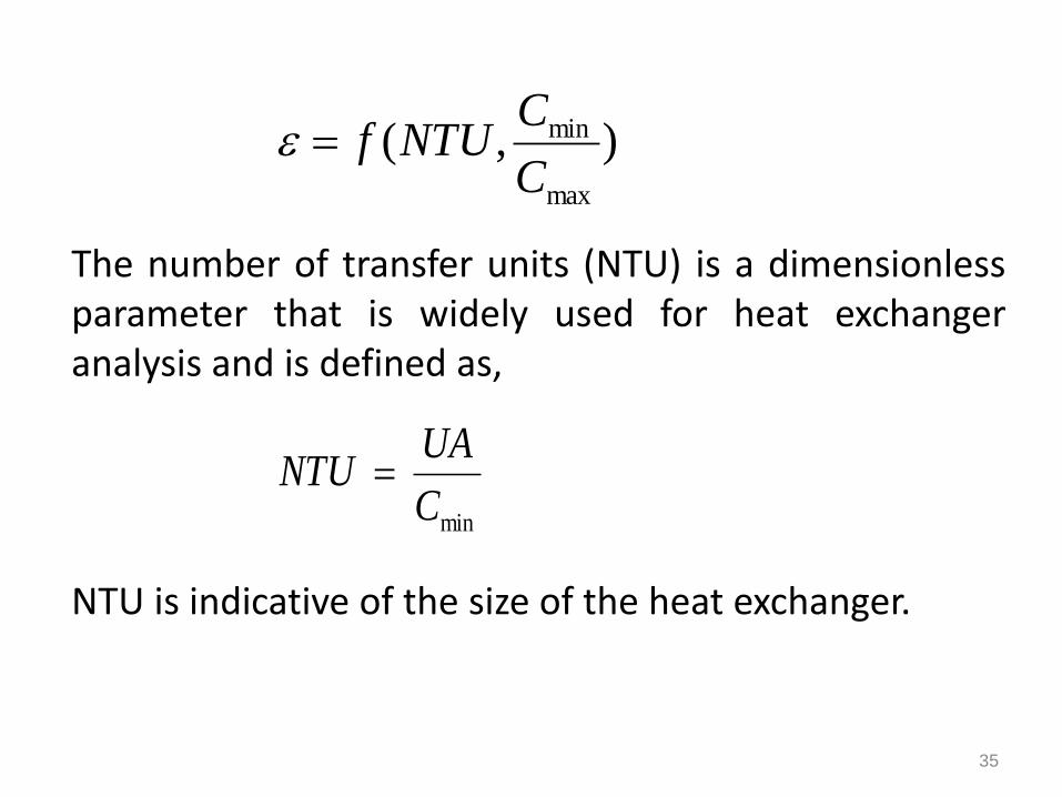
The number of transfer units (NTU) is a dimensionlessparameter that is widely used for heat exchangeranalysis and is defined as,
NTU is indicative of the size of the heat exchanger.
35
),(max
min
C
CNTUf
min
C
UANTU
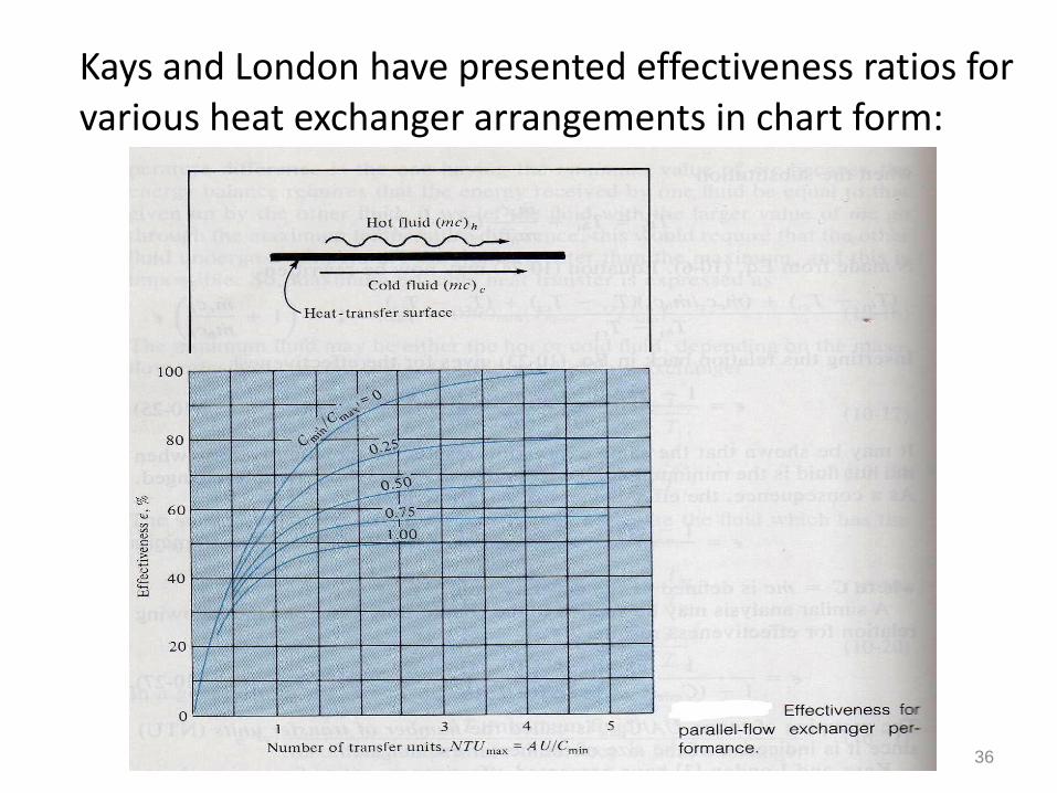
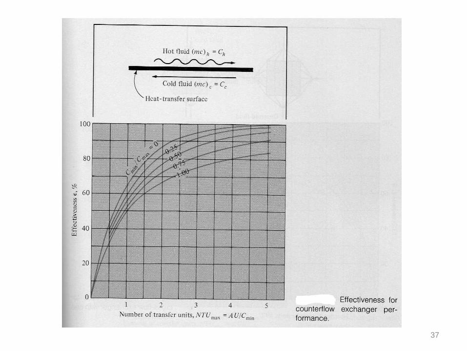
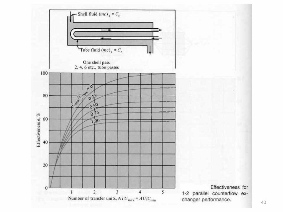
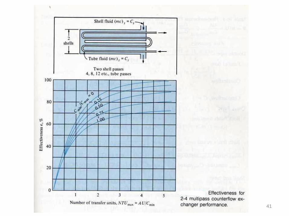
Kays and London have presented effectiveness ratios for various heat exchanger arrangements in chart form:
36
37

38

39
40
41

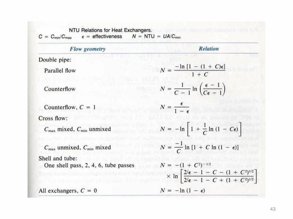
The effectiveness and the NTU in terms of effectiveness and capacity ratio are listed in the tables:
42
43