
Heat and Mass Transfer Studies on 134 A-DMAC Based … · Heat and Mass Transfer Studies on 134...
9
Heat and Mass Transfer Studies on 134 A-DMAC Based Falling Film Absorbers for Absorption Refrigeration System S.THARVES MOHIDEEN 1 AND S.RENGANARAYANAN Institute for Energy Studies, Anna University, Chennai, India – 600 025 1 Department of Mechanical Engineering, Institute of Road & Transport Technology, Erode, TamilNadu INDIA -638316 E-mail: [email protected] Phone:+19366724100 Fax: +914242533590 Abstract-: Absorber is an important component in Vapour Absorption Refrigeration System and its performance has greater influence in overall efficiency of absorption machines. Falling film heat and mass transfer in an absorber is greatly influenced by fluid properties, geometry of heat exchanger and its operating parameters. This paper presents on the results of experimental studies on the heat and mass transfer characteristics of horizontal, vertical and coiled tube falling film absorbers using 1,1,1,2-Tetrafluroethane(R-134a) and N-N Dimethyl Acetamide (DMAC) as working fluids. The effects of film Reynolds number and cooling water temperature on absorber heat load, over all heat transfer co-efficient and mass of refrigerant absorbed for the said three configurations are presented discussed and compared. The experimental values of overall heat transfer coefficient are found to be 745, 320 and 230 w/m 2 K for coil, vertical and horizontal tubes respectively. Among the configurations tested, the shell and coiled tube absorber was found to yield higher heat transfer coefficient and also more compact. When all the other parameters are kept constant, if the cooling water temperature is reduced from 30 ºC to 25 ºC, the absorber heat load and refrigerant mass absorption rate is increased by 16.3% and 15 % respectively. Key words: Heat and mass transfer performance: falling film absorbers: R134aDMAC: Film Reynolds Number: Overall heat transfer coefficient Proceedings of the 4th WSEAS Int. Conf. on HEAT TRANSFER, THERMAL ENGINEERING and ENVIRONMENT, Elounda, Greece, August 21-23, 2006 (pp342-350)
Transcript of Heat and Mass Transfer Studies on 134 A-DMAC Based … · Heat and Mass Transfer Studies on 134...

Heat and Mass Transfer Studies on 134 A-DMAC Based Falling Film
Absorbers for Absorption Refrigeration System
S.THARVES MOHIDEEN1 AND S.RENGANARAYANAN
Institute for Energy Studies, Anna University, Chennai, India – 600 025
1Department of Mechanical Engineering,
Institute of Road & Transport Technology,
Erode, TamilNadu
INDIA -638316
E-mail: [email protected]
Phone:+19366724100
Fax: +914242533590
Abstract-: Absorber is an important component in Vapour Absorption Refrigeration System and its
performance has greater influence in overall efficiency of absorption machines. Falling film heat and
mass transfer in an absorber is greatly influenced by fluid properties, geometry of heat exchanger and
its operating parameters. This paper presents on the results of experimental studies on the heat and
mass transfer characteristics of horizontal, vertical and coiled tube falling film absorbers using
1,1,1,2-Tetrafluroethane(R-134a) and N-N Dimethyl Acetamide (DMAC) as working fluids. The
effects of film Reynolds number and cooling water temperature on absorber heat load, over all heat
transfer co-efficient and mass of refrigerant absorbed for the said three configurations are presented
discussed and compared. The experimental values of overall heat transfer coefficient are found to be
745, 320 and 230 w/m2 K for coil, vertical and horizontal tubes respectively. Among the configurations
tested, the shell and coiled tube absorber was found to yield higher heat transfer coefficient and also
more compact. When all the other parameters are kept constant, if the cooling water temperature is
reduced from 30 ºC to 25 ºC, the absorber heat load and refrigerant mass absorption rate is increased by
16.3% and 15 % respectively.
Key words: Heat and mass transfer performance: falling film absorbers: R134aDMAC:
Film Reynolds Number: Overall heat transfer coefficient
Proceedings of the 4th WSEAS Int. Conf. on HEAT TRANSFER, THERMAL ENGINEERING and ENVIRONMENT, Elounda, Greece, August 21-23, 2006 (pp342-350)
1 Introduction
Simultaneous heating and cooling are
required in many industries such as dairy plant
pharmaceuticals chemical etc,. Absorption systems
have been extensively paid attention in recent years
due to the potential for CFC and HCFC
replacements in refrigeration, heating and cooling
applications. The absorber in any absorption
machine is a key component and its characteristics
have significant effects on overall efficiency of
absorption machines.
The heat transfer area of absorber alone
might account for 40% of the total heat transfer area
in absorption machines [1]. Previous published
works have developed an understanding of the
transport processes in both laminar and turbulent
absorber falling films. Absorption phenomena in
falling film absorber have been widely investigated
by many researchers [1-6] to predict the heat and
mass transfer performance of various geometric
configuration of absorber, with H2O-LiBr and
ammonia-water as working fluids. Deng et al. [1]
have conducted experimental studies on heat and
mass transfer characteristics of falling film H2O-
LiBr absorber, which was made up of 24 smooth
horizontal tubes. They concluded that there is an
spray density of solution, at which the heat transfer
co-efficient, is maximum. They also found that
when coolant temperature is decreased from 32º C
to 30º C, the absorber flux was increased by 17%.
Jeffrey Seewald [2] has developed a model
to investigate heat and mass transfer processes of
H2O-LiBr Coil tube absorber. He observed that
when solution flow rate is increased, the overall
heat transfer co-efficient also increases and
optimum value is obtained. The absorber
performance was benefited from higher inlet
absorbent concentration.
Kang et al. [3] proposed a modeling method
for concurrent flow of vapour liquid in fluted tubes
with ammonia-water solution, including heat and
mass transfer in the vapour region. Their
computations illustrated that the heat exchanger size
is affected strongly by the temperature difference
between liquid-vapour interface and vapour
velocity.
Siyoung Jeong et al. [4] have found
experimentally the Re-Nu relations for coiled tube
absorber with ammonia-water as working fluid.
Perez-Blanco [5] developed a model for the
absorption of ammonia into a falling film around
coiled tubes. By comparing numerical prediction
with experimental results, he concluded that the
mass transfer process in the falling film controlled
the absorption rate so that vapour velocity must be
optimized to increase the absorption rate.
Kang et al. [6] carried out experimental
investigation to verify the heat and mass transfer
process that occurs simultaneously in a coiled tube
absorber. They examined the effects of various
operating conditions in the heat and mass transfer.
They also suggested experimental co-relations for
Nusselt and Sherwood numbers.
Sujatha et al. [7,8] conducted experiments
on a vertical tubular bubble absorber operating with
HCFC22-DMF and have obtained the overall heat
transfer co-efficient of 195 W/m2 K.
Muthu [9] has done experimental studies on
Performance of R-134a – DMAC based absorption
cooling system using low potential thermal sources.
He proved that R-134a – DMAC based absorption
cooling system yielded an optimum COP of 0.4,
when the heat source temperature is 70 ºC.
Falling film heat transfer mode provides
relatively high heat transfer coefficient and is stable
during operation and is easy to manufacture [5]. It
has been observed that the falling vertical films have
a wavy character. A wave film leads to surface
renewal and mixing of fluid, which efficiently
enhances the heat transfer rates. The wave
frequency has strong impact on heat and mass flux
of absorber [2].
In the previous works performed by the
authors [1-6], it was found that the working
substances used are either water-lithium bromide or
ammonia-water. As ammonia has its own
limitations due to its non compatibility with copper
and high specific volume where as production of
sub-zero temperature and crystallization are the two
main demerits associated with water-Lithium
bromide systems and to add upon, these two
working fluids require higher heat source
temperature.
R-134a-DMAC working fluid pair is having
Zero Ozone Depletion Potential and negligible
Global Warming Potential with a comparatively
lesser heat source temperature [10]. Arivalagan
Proceedings of the 4th WSEAS Int. Conf. on HEAT TRANSFER, THERMAL ENGINEERING and ENVIRONMENT, Elounda, Greece, August 21-23, 2006 (pp342-350)
et.al [11] have observed that R134a-DMAC
refrigerant-absorbent combination may considered
as the one of the most favorable working fluids
when a half effect system is to be operated with low
temperature heat sources.
Hence the objectives of these studies are to
analyze the heat and mass transfer performance
characteristics of horizontal, vertical and coiled tube
falling film absorber with R-134a-DMAC as
working fluid. In this study the effects of film
Reynolds number, Cooling water temperature on
absorber heat load, overall heat transfer co-efficient
and mass of refrigerant absorbed eco-friendly
working fluid (R-134a – DMAC) are presented and
discussed.
2 Experimental set-up and Procedure
The experimental set up used in this
investigation is depicted schematically in Fig
(1).The main components are shell and coil tube
absorber, horizontally cooled and vertically cooled
absorbers, evaporator, generator, solution pump,
condenser and strong solution tank.
2.1 Coiled tube absorber
The absorbent solution N-N-Dimethyl
Acetamide (DMAC) flows down the outer surface
of the coiled tube as a form of liquid film and
consequently 1,1,1,2 Tetrafluoroethane (R-134a)
vapour is absorbed into the liquid film. The heat of
absorption is removed by the cooling water, which
is flowing inside the coiled tube. The cooling water
system consists of a constant temperature water tank
with temperature controller, a centrifugal water
pump and a water flow meter.
2.2 Vertical tube absorber
The absorbent solution N-N-Dimethyl
acetamide (DMAC) flows down as a falling film
through the inner surface of the vertical tube and
consequently 1,1,1,2 Tetrafluoroethane (R-134a)
vapour coming from the bottom of the vertical tube
is absorbed into the falling liquid film. The heat of
absorption is removed by the cooling water, which
is flowing through the annulus space of the
concentric vertical tube.
2.3 Horizontal Tube absorber
The absorbent solution N-N-Dimethyl
acetamide (DMAC) flows down the outer surface of
the falling film horizontal tube as a form of liquid
film and consequently 1,1,1,2 Tetrafluoroethane (R-
134a) vapour is absorbed into the liquid film. The
heat of absorption is removed by the cooling water,
which is flowing inside the tube.
For the same operating conditions, all the
three configurations of falling film absorber were
tested one by one by using the flow control valves
fitted at the inlets and outlets of the respective
absorber for the solution, cooling water and
refrigerant
2.5 Test Conditions:
Table 2:Test conditions Solution inlet conditions:
Pressure : 3.2 bar
Concentration (refrigerant) : 0.43
Temperature : 48o C
Flow rate : 0.012,0.0160,0.02
and 0.024 kg/s
Cooling water and Refrigerant inlet
conditions:
Flow rate : 0.04 kg/s
Temperature : 20 oC, 25
oC, 30
oC
Refrigerant temperature : 5 oC
2.6 Test processes:
The strong refrigerant solution is first
pumped to the generator, where the R-134a vapour
was driven out by circulating hot water and weak
refrigerant solution at specified pressure and
temperature is then supplied to the absorber through
a eight way solution distributor, which exactly
directs the solution to the outer surface of a coiled
tube, inner surface of the vertical tube and outer
surface of the horizontal tube. The test absorber is
equipped with proper regeneration arrangements for
both refrigerant and absorbent solution. This
arrangement consists of an evaporator, condenser
and generator as depicted in fig (1). Absorption of
R-134a vapour takes place on the wetted surface of
the absorber tubes and the heat of absorption is
removed away by flow of cooling water through the
each absorbers. The strong refrigerant solution is
collected back in the solution tank, under the
absorber.
Proceedings of the 4th WSEAS Int. Conf. on HEAT TRANSFER, THERMAL ENGINEERING and ENVIRONMENT, Elounda, Greece, August 21-23, 2006 (pp342-350)

Figure (4.1) schematic diagram of the experimental setup
Gate valve
Angle valve
Needele valve
Diaphgram valve
Flow Measurement
Pressure Measurement
Temperature Measurement
Refrigeration load
simulator
from hotwater
simulator
Coiled
tube
absorber
Vertical
tube
absorber Horizontal tube
absorber
HEATER
CHILLER
Generator
Hot water Out
Coolant In
Coolant Out
Evaporator
134 A
Receiver
Solution
Tank
Proceedings of the 4th WSEAS Int. Conf. on HEAT TRANSFER, THERMAL ENGINEERING and ENVIRONMENT, Elounda, Greece, August 21-23, 2006 (pp342-350)
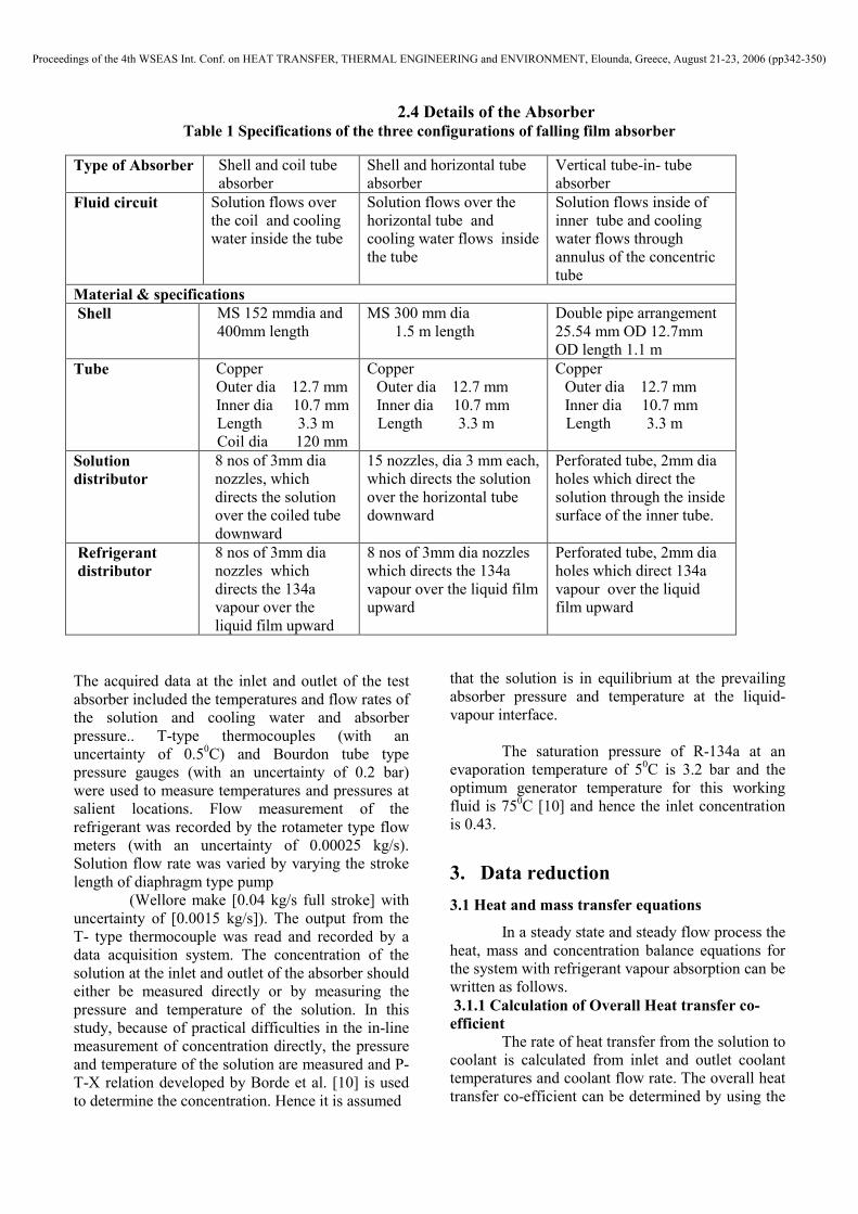
2.4 Details of the Absorber Table 1 Specifications of the three configurations of falling film absorber
The acquired data at the inlet and outlet of the test
absorber included the temperatures and flow rates of
the solution and cooling water and absorber
pressure.. T-type thermocouples (with an
uncertainty of 0.50C) and Bourdon tube type
pressure gauges (with an uncertainty of 0.2 bar)
were used to measure temperatures and pressures at
salient locations. Flow measurement of the
refrigerant was recorded by the rotameter type flow
meters (with an uncertainty of 0.00025 kg/s).
Solution flow rate was varied by varying the stroke
length of diaphragm type pump
(Wellore make [0.04 kg/s full stroke] with
uncertainty of [0.0015 kg/s]). The output from the
T- type thermocouple was read and recorded by a
data acquisition system. The concentration of the
solution at the inlet and outlet of the absorber should
either be measured directly or by measuring the
pressure and temperature of the solution. In this
study, because of practical difficulties in the in-line
measurement of concentration directly, the pressure
and temperature of the solution are measured and P-
T-X relation developed by Borde et al. [10] is used
to determine the concentration. Hence it is assumed
that the solution is in equilibrium at the prevailing
absorber pressure and temperature at the liquid-
vapour interface.
The saturation pressure of R-134a at an
evaporation temperature of 50C is 3.2 bar and the
optimum generator temperature for this working
fluid is 750C [10] and hence the inlet concentration
is 0.43.
3. Data reduction
3.1 Heat and mass transfer equations
In a steady state and steady flow process the
heat, mass and concentration balance equations for
the system with refrigerant vapour absorption can be
written as follows.
3.1.1 Calculation of Overall Heat transfer co-
efficient The rate of heat transfer from the solution to
coolant is calculated from inlet and outlet coolant
temperatures and coolant flow rate. The overall heat
transfer co-efficient can be determined by using the
Type of Absorber Shell and coil tube
absorber
Shell and horizontal tube
absorber
Vertical tube-in- tube
absorber
Fluid circuit
Solution flows over
the coil and cooling
water inside the tube
Solution flows over the
horizontal tube and
cooling water flows inside
the tube
Solution flows inside of
inner tube and cooling
water flows through
annulus of the concentric
tube
Material & specifications
Shell
MS 152 mmdia and
400mm length
MS 300 mm dia
1.5 m length
Double pipe arrangement
25.54 mm OD 12.7mm
OD length 1.1 m
Tube
Copper
Outer dia 12.7 mm
Inner dia 10.7 mm
Length 3.3 m
Coil dia 120 mm
Copper
Outer dia 12.7 mm
Inner dia 10.7 mm
Length 3.3 m
Copper
Outer dia 12.7 mm
Inner dia 10.7 mm
Length 3.3 m
Solution
distributor
8 nos of 3mm dia
nozzles, which
directs the solution
over the coiled tube
downward
15 nozzles, dia 3 mm each,
which directs the solution
over the horizontal tube
downward
Perforated tube, 2mm dia
holes which direct the
solution through the inside
surface of the inner tube.
Refrigerant
distributor
8 nos of 3mm dia
nozzles which
directs the 134a
vapour over the
liquid film upward
8 nos of 3mm dia nozzles
which directs the 134a
vapour over the liquid film
upward
Perforated tube, 2mm dia
holes which direct 134a
vapour over the liquid
film upward
Proceedings of the 4th WSEAS Int. Conf. on HEAT TRANSFER, THERMAL ENGINEERING and ENVIRONMENT, Elounda, Greece, August 21-23, 2006 (pp342-350)

following relation, if temperatures of the coolant
and solution at the inlet and outlet of the absorber
are known. The following expressions were referred
from the literature [6].
The heat transfer area is kept constant at
0.13 m2for all the three configuration of the
absorbers
U = Qa / A∆Tm (1)
∆Tm = (Tsi – Tcwo) – (Tso – Tcwi)
ln{(Tsi – Tcwo)/(Tso – Tcwi)}
Qa = mcw Cpw (Tcwo – Tcwi) (2)
Qe = m Cp(Tei—Teo) (3)
Calculation of refrigerant mass absorption rate
msi + mr = mso (4)
msiXsi + mrXr = msoXso (5)
Qa = (msihsi + mrhr - msohso )
= mcwCpcw (Tcwo-Tcwi) (6)
On combining equations (4) and (5). The mass of
refrigerant absorbed is
mr = msi (Xso-Xsi) / Xsi (7)
The temperature and concentration satisfy
the phase equlibrium relationship that is expressed
as P-T-X relation, developed by Borde.I and
Jeleneik [10]
X=f (p,t) (8)
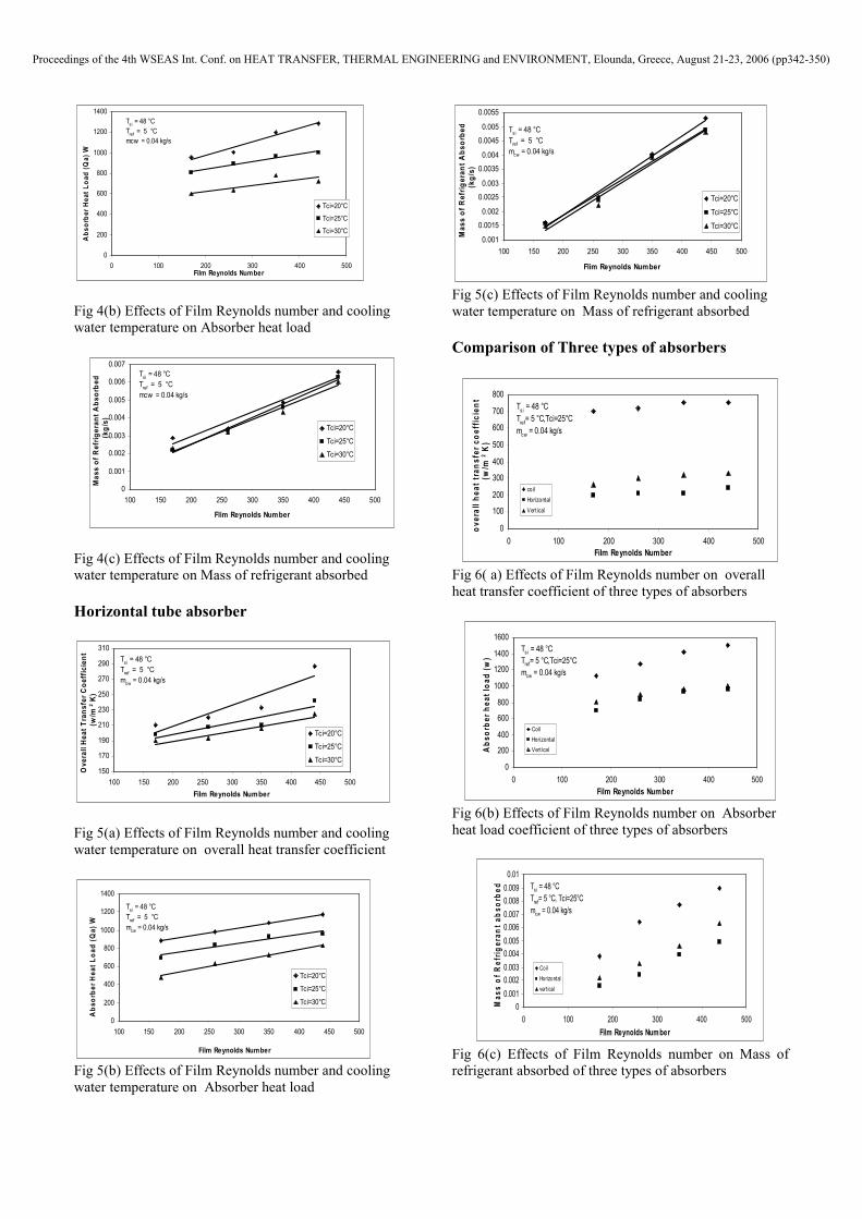
4 Results and Discussions
4.5 Effects of Film Reynolds number on
overall heat transfer Co-efficient and
absorption Heat load.
The heat and mass transfer characteristics of
the three falling film absorber configurations was
studied at the film Reynolds number from 170 to
440, at various inlet cooling water temperatures It is observed from Figs 3(a) ,3 (b), 4(a) ,4 (b), 5(a) and
5 (b). that for a constant inlet cooling water and
solution temperatures, the overall heat transfer Co-
efficient and absorber heat load increase with
increase in solution flow rate, for all the three
configurations
Coiled Tube Absorber
Fig 3(a) Effects of Film Reynolds number and cooling
water temperature on overall heat Transfer co-efficient
Tsi=48 ºC, Mcw =0.04 kg/ s
0
200
400
600
800
1000
1200
1400
1600
1800
2000
100 200 300 400 500
Film Renolds number
Absorber Heat load(Qa) W
Tci = 20ºC
Tci = 25ºC
Tci = 30ºC
Fig 3 (b) Effects of Film Renolds number and cooling
water temperature on absorber heat Load Tsi=48
ºC, mcw=0.04 kg/s.
0
0.001
0.002
0.003
0.004
0.005
0.006
0.007
0.008
0.009
0.01
100 200 300 400 500
Film Reynolds number
Mass of Refrigerant Absorbed,kg/s
Tci=20ºC
Tci=25ºC
Tci=30ºC
Fig 3 (c) Effects of Film Reynolds number and cooling
water temperature on Mass of refrigerant absorbed
Tsi=48 ºC, mcw=0.04 kg/s.
Vertical tube absorber
200
220
240
260
280
300
320
340
360
100 150 200 250 300 350 400 450 500
Film Reynolds Number
Overall Heat Transfer
Coefficient (w
/m2 K)
Tci=20°C
Tci=25°C
Tci=30°C
Tsi = 48 °C
Tref = 5 °C
mcw = 0.04 kg/s
Fig 4(a) Effects of Film Reynolds number and cooling
water temperature on overall heat transfer coefficient
Proceedings of the 4th WSEAS Int. Conf. on HEAT TRANSFER, THERMAL ENGINEERING and ENVIRONMENT, Elounda, Greece, August 21-23, 2006 (pp342-350)
0
200
400
600
800
1000
1200
1400
0 100 200 300 400 500Film Reynolds Number
Absorber Heat Load (Qa) W
Tci=20°C
Tci=25°C
Tci=30°C
Tsi = 48 °C
Tref = 5 °C
mcw = 0.04 kg/s
Fig 4(b) Effects of Film Reynolds number and cooling
water temperature on Absorber heat load
0
0.001
0.002
0.003
0.004
0.005
0.006
0.007
100 150 200 250 300 350 400 450 500
Flim Reynolds Number
Mass of Refrigerant Absorbed
(kg/s)
Tci=20°C
Tci=25°C
Tci=30°C
Tsi = 48 °C
Tref = 5 °C
mcw = 0.04 kg/s
Fig 4(c) Effects of Film Reynolds number and cooling
water temperature on Mass of refrigerant absorbed
Horizontal tube absorber
150
170
190
210
230
250
270
290
310
100 150 200 250 300 350 400 450 500
Film Reynolds Number
Overall Heat Transfer Coefficient
(w/m
2 K)
Tci=20°C
Tci=25°C
Tci=30°C
Tsi = 48 °C
Tref = 5 °C
mcw = 0.04 kg/s
Fig 5(a) Effects of Film Reynolds number and cooling
water temperature on overall heat transfer coefficient
0
200
400
600
800
1000
1200
1400
100 150 200 250 300 350 400 450 500
Film Reynolds Number
Absorber Heat Load (Qa) W
Tci=20°C
Tci=25°C
Tci=30°C
Tsi = 48 °C
Tref = 5 °C
mcw = 0.04 kg/s
Fig 5(b) Effects of Film Reynolds number and cooling
water temperature on Absorber heat load
0.001
0.0015
0.002
0.0025
0.003
0.0035
0.004
0.0045
0.005
0.0055
100 150 200 250 300 350 400 450 500
Flim Reynolds Number
Mass of Refrigerant Absorbed
(kg/s)
Tci=20°C
Tci=25°C
Tci=30°C
Tsi = 48 °C
Tref = 5 °C
mcw = 0.04 kg/s
Fig 5(c) Effects of Film Reynolds number and cooling
water temperature on Mass of refrigerant absorbed
Comparison of Three types of absorbers
0
100
200
300
400
500
600
700
800
0 100 200 300 400 500
Film Reynolds Number
overall heat transfer coefficient
(w/m
2 K)
coil
Horizontal
Vert ical
Tsi = 48 °C
Tref= 5 °C,Tci=25°C
mcw = 0.04 kg/s
Fig 6( a) Effects of Film Reynolds number on overall
heat transfer coefficient of three types of absorbers
0
200
400
600
800
1000
1200
1400
1600
0 100 200 300 400 500
Film Reynolds Number
Absorber heat load (w)
Coil
Horizontal
Vert ical
Tsi = 48 °C
Tref= 5 °C,Tci=25°C
mcw = 0.04 kg/s
Fig 6(b) Effects of Film Reynolds number on Absorber
heat load coefficient of three types of absorbers
0
0.001
0.002
0.003
0.004
0.005
0.006
0.007
0.008
0.009
0.01
0 100 200 300 400 500
Film Reynolds Number
Mass of Refrigerant absorbed
Coil
Horizontal
vert ical
Tsi = 48 °C
Tref= 5 °C, Tci=25°C
mcw = 0.04 kg/s
Fig 6(c) Effects of Film Reynolds number on Mass of
refrigerant absorbed of three types of absorbers
Proceedings of the 4th WSEAS Int. Conf. on HEAT TRANSFER, THERMAL ENGINEERING and ENVIRONMENT, Elounda, Greece, August 21-23, 2006 (pp342-350)

This phenomenon can be explained as follows.
Increase in Film Reynolds number improves the
fluid characteristics and wet ratio of the heat transfer
area, which contribute to the enhancement of heat
and mass transfer.
In the present study, the overall heat transfer co-
efficient and absorber heat load for a coil absorber
operating with R-134a DMAC was found to be 745
w/m2k 1080 W respectively, for a film Reynolds
number of 350 and inlet cooling water temperature
of 25 ºC. Similarly the overall heat transfer
coefficient for vertical tube and horizontal tube
absorbers are found to be 320 and 230 W/m2 K
respectively
It is learnt from Fig 6(a) that the Overall
heat transfer co-efficient is relatively higher for
coiled tube configuration, which is due to the
fact that the coolant side heat transfer co-
efficient is relatively higher for coil tube
absorber than the straight tube, which improves
the overall heat transfer co-efficient.
Similar experimental studies for ammonia-
water coil absorber by Siyoung jeong et.al [4]
yielded that the overall heat transfer co-efficient in
the film Reynolds number range of 100 to 400, was
found to vary from 200 to 650 w/m2k. A model
developed by Jeffrey S.Seewald [2] to predict
performance of water-liBr coil absorber indicated
that the value of overall heat transfer co-efficient
was 700 w/m2k.
4.6 Effects of Film Reynolds number on
mass of refrigerant absorbed:
From the Figs 3(c), 4(c)and 5(c), When inlet
cooling water temperature and absorber pressure is
constant, the refrigerant mass absorption rate
increases with increase with increase in Film
Reynolds number. The experimental value for coil,
vertical and horizontal is 0.007, 0.0046, and 0.0035
respectively. This is because, for a constant inlet
concentration, the mass balance across absorber
revealed that the mass absorbed is proportional to
solution flow rate and hence Film Reynolds number.
It is also observed from fig 6(c) that, at a constant
solution flow rate and inlet solution and cooling
water temperatures the mass absorption rate is
higher for coiled tube configuration followed by
vertical tube and horizontal tube absorbers. This is
due to the higher value of overall heat transfer
coefficient of coiled tube absorber which causes the
relatively faster rate of heat transfer from the
solution to the cooling water.
4.7 Effects of cooling water temperature on
heat transfer co- efficient, absorber load and
mass absorption rate
It is learnt from in Figs 3(a, b, c), 4(a, b,
c) and 5(a, b, c). All the three parameters followed a
similar trend when the inlet cooling water
temperature is increased from 20 to 30ºC, the heat
and mass transfer performance was found to decline.
This can be explained as follows. At lower cooling
water temperature, the heat transfer rate from
solution to coolant is increased, which improves the
absorption rate. When all the other parameter are
kept constant if the cooling water temperature is
decreased from 30 to 25 ºC, the overall heat transfer
coefficient is improved by 11%, 15 % and 5 % for
coiled tube, vertical tube and horizontal tube
absorbers respectively. Similar improvements are
also absorbed in absorber heat load and mass of the
refrigerant absorbed.
The error in heat transfer coefficient
absorber heat load etc., is calculated using the
method proposed by Kline and McClinltock [12].
Uncertainty in overall heat transfer coefficient is 4%
and absorber heat load is 3.7%.
5. Conclusions
Three configurations of falling film absorbers with R134a-DMAC as working fluid was designed
and built to suit 1kW cooling capacity evaporator
and their heat and mass transfer characteristics were investigated and the results are compared.
The effects of film Reynolds number and
cooling water temperature on absorber heat load,
over all heat transfer co-efficient and mass of
refrigerant absorbed for the said three configurations
are presented. The experimental values of overall
heat transfer coefficient are found to be 745, 320
and 230 w/m2 K for coil, vertical and horizontal
tubes respectively. For the same heat transfer
surface area, among the configurations tested, the
shell and coiled tube absorber was found to yield
higher heat transfer coefficient and also more
compact.
The effect of cooling water temperature is
significant in the design of absorbers When all the
Proceedings of the 4th WSEAS Int. Conf. on HEAT TRANSFER, THERMAL ENGINEERING and ENVIRONMENT, Elounda, Greece, August 21-23, 2006 (pp342-350)
other parameters are kept constant, if the cooling
water temperature is reduced from 30 ºC to 25 ºC,
the absorber heat load and refrigerant mass
absorption rate is increased by 16.3% and 15 %
respectively.
These results can be used as a reference in
designing actual absorption chiller, heat pump and
heat transformers, operating with R134a- DMAC as
working fluids.
6. Nomenclature
m - Mass flow rate in kg/s
X - Concentration by weight
Q – Absorber heat load in kW
h – Enthalpy in kJ/kg
Cp – Specific heat in kJ/kg k
U – Overall heat transfer co-efficient in
kW/ m2k
A – Heat transfer area in m2
∆Tm - Log Mean Temperature difference
(LMTD) in k
Re – Reynolds Number
K - Thermal Conductivity in W/m k
d – diameter of tube in m
D – Diameter of coil in m
T - Temperature, ºC
Subscripts
a – Absorber
r – Refrigerant
ei - evaporator inlet
eo - evaporator inlet
si - Solution Inlet
so – Solution Inlet
cwo – cooling water outlet
cwi - cooling water inlet
g -generator
References:
[1] S.M Deng and Ma, Experimental studies on characteristics of an absorber using Li-Br/H2O
solution as working fluid, International journal
of refrigeration (1999) 293-301.
[2] S. Jeffrey Seewald, A simple model for the performance of a Li-Br/H2O coil absorber,
ASHRAE transactions Research 3814 (1994)
318-328.
[3] Kang and Christensen, Development of
concurrent model for vertical fluted tube GAX
absorber, proceedings of the International Heat
Pump Conference (1994) 7-14.
[4] Siyoung Jeong, Dr.Ing, Heat transfer
performance of a coiled tube absorber with
working fluid ammonia-water, ASHRAE
transaction- symposia CF-93-21-4 (1999) 1577-
1583.
[5] H Perez- Blanco, A model of an ammonia absorber,ASHRAE transactions(1988-94) 67-83.
[6] Y.T Kang, A Akosawa, T Kashiwaki, Experimental co-relation of combined HMT for ammonia / water falling film absorption, International journal of Refrigeration 22 (4) (1998) 250-262.
[7] K.S Sujatha, Mani and Srinivasamoorthy, Heat and mass transfer 32 (1997) 255-266
[8] K.S Sujatha, Mani and Srinivasamoorthy, Experiments on a bubble Absorber. Int.Comn.
Heat and mass transfer 26 (7) (1999).
[9] V.Muthu “A Ph.D Thesis on Studies of
Vapour Absorption Refrigeration System for
exploiting low potential thermal sources,
Anna University ,2003.
[10] I.Borde , M.Jelinek ,N.C Daltrophe ,
Absorption based on R-134a, International
Journal of Energy Research 18: (1995) 387-
394.S.
[11] S.N Arivazhagan,. Murugesan, R. Saravanan and S.Renganarayanan,, Simulation studies on R134a—DMAC based half effect absorption cold storage systems, Energy Conversion and Management, Volume 46, Issues 11-12, July 2005,Pages1703-1713
[12] S.J. Kline and F. A.McClinltock , Mech.
Engg. Journal, 7l5, 224 (1953
Proceedings of the 4th WSEAS Int. Conf. on HEAT TRANSFER, THERMAL ENGINEERING and ENVIRONMENT, Elounda, Greece, August 21-23, 2006 (pp342-350)