
Heart of The Matter HLD - EE Senior Design
13
High Level Design The Heart of the Matter Brendan Galloway Ana Isabel Guzman Allison Walker Nicole Wardeberg
Transcript of Heart of The Matter HLD - EE Senior Design

High Level Design
The Heart of the Matter
Brendan Galloway Ana Isabel Guzman
Allison Walker Nicole Wardeberg

Fall 2016 High Level Design
Heart of the Matter 2 EE Senior Design
Table of Contents Introduction 3
Problem Statement and Proposed Solution 3
System Requirements 4
System Block Diagram 6 Overall System 6 Subsystem and Interface Requirements: 7
Photodiode captures LED light 8 Microcontroller receives current signal 8 Microcontroller sends continuous data to storage unit 8 Storage unit stores data sent from microcontroller 8 Battery powers all components 8 Software algorithm 8 Software user interface 9
Future Enhancement Requirements 9
High Level Design Decisions 9 Microcontroller dictates LED flashing rates 9 Sensor receives current signal 9 Microcontroller sends continuous data to storage unit 9 Battery powers all components 9 Software and user interface 10 Software user interface 10
Open Questions 10
Major Component Costs 10
Conclusions 11

Fall 2016 High Level Design
Heart of the Matter 3 EE Senior Design
1 Introduction
Cardiomyopathy, enlarged heart syndrome, causes the walls of the heart to thicken to an abnormal degree. While several types of cardiomyopathy are common among people, hypertrophic cardiomyopathy is one of the most common among young people, especially athletes, who suffer from unexpected cardiac arrest. As the walls of the heart thicken, blood is unable to pass through the ventricle. While symptoms of the disease do not exist for many carriers of cardiomyopathy, this obstruction often presents itself as heart arrhythmias. Young athletes who participate in rigorous physical activities are more likely to suffer from heart arrhythmias, and more severely, cardiac arrest, due to cardiomyopathy. Tests for cardiomyopathy are not integrated into standard physicals, so the disease is difficult to catch until severe problems arise. The purpose of our Senior Design project is to create a device which looks for signs of this disease.
2 Problem Statement and Proposed Solution
Physicians usually do not specifically test for cardiomyopathy due to the rarity of the disease and because ultrasounds and x-rays, the only completely accurate tests to determine enlarged hearts, are expensive. Our senior design project aims at looking for symptoms of the disease, specifically abnormal pulses (arrhythmia) and blood oxygenation levels. People with cardiomyopathy often have pulses with a “twice beating” rhythm, which are occasionally difficult to detect with a standard touch or stethoscope testing. Oxygen level testing is absent entirely from most standard check-ups. However, abnormalities in both pulses and oxygen levels may point to larger problems in the heart. The device we create will be able to show abnormalities that would prompt the patient to get further testing.
We plan to create a photoplethysmography (PPG) instrument to observe blood oxygenation levels and heartbeat regularity. Photoplethysmography is an optical method of measuring an organ’s volume by way of infrared and red light. The change in volume caused by the pressure pulse is measured according to the amount of light transmitted to a photodiode. The microcontroller at the center of the device will determine the alternating flash rate of the infrared and red lights, and to process the data collected by the photodiode. The data will be stored in a micro SD card. It can later be transferred to a computer to show the measured waveform of the heart’s cycles (displaying any recordable arrhythmia), as well as outputting to the terminal an actual pulse rate and oxygen absorption levels within the blood.

Fall 2016 High Level Design
Heart of the Matter 4 EE Senior Design
3 System Requirements
● What is the nature of the required embedded intelligence? The overall system requires communication between several components. The microcontroller will set the blinking rates of the two LEDs. Once the light from the LEDs travels through the skin and blood vessels, the photodiode will capture any light not absorbed by the body, and convert that light into current. The AFE4490, once again, will the current signal from the photodiode and convert the data from analog to digital for it to be passed to the microcontroller. Once the microcontroller receives this signal, it will send the data to the micro SD card for storage. In general, the embedded intelligence of the system relies on communication between the microcontroller and all other elements. ● How is the device powered? If it runs on batteries, what kinds of batteries are
used, how long should the system be able to run on the batteries, etc.? The final prototype of our design aims at continuously collecting data on the wearable device. In order to achieve this, the wearable device will be powered by a battery. We think the best approach to deciding what battery to use is creating an initial prototype that runs off of the power from a computer while being plugged in via a USB port. The micro SD card, which will store the data, LEDs, photodiode, and microcontroller, will all require power. Therefore, we want to make a decision on the battery capacity once we have the device working while hard-wired with computer power. ● There are lots of requirements related to wireless interfaces. How many devices
need to be supported? What range is required? Our project does not require wireless communication. We intend on keeping a data storage unit (micro SD card) in the device while the subject is wearing it. When data is to be interpreted, the data card will be removed from the wearable device and connected directly to the computer. A wireless interface could be an upgrade in future models. ● What are the user interfaces?
The user interface will be a computer program that takes the data from the micro SD card and interprets it. The program will include a GUI that allows the user to choose what he/she wants to see. The capabilities of the program will include graphical presentation of the heart pulse and oxygenation levels and warnings if abnormalities of these measurements are reflected in the data. ● How is the system installed and used?

Fall 2016 High Level Design
Heart of the Matter 5 EE Senior Design
The system will be a wearable device, either on the finger, wrist, or ear. We will determine which body part to use by experimenting with how much light is absorbed by each placement. We need to consider the lowest signal we can measure with the system and how much light that corresponds to. We will determine this by testing to see how much light can be captured versus body part and skin thickness. For example, if the wrist captures almost all of the light, then the signal would be too small to extract enough useful data. Regardless of body placement, this wearable device will ultimately be powered by a battery for continuous use. Two flashing LEDs will produce light, the blood and skin will absorb some of the light, and the photodiode will capture the excess light and send the signal to the microcontroller through the AFE4490. A micro SD card will store the data sent from the microcontroller. The micro SD card can be extracted from the wearable device at any time and connected to a computer. Once connected to a computer, a program created by our team will take the data and interpret it into graphs and readable format. Because the project aims at determining issues with heart pulse or oxygenation levels, any abnormalities will be flagged by the program and prompt the user to consider further testing from a trained physician. ● If your project involves voltages and or currents that may be dangerous, what are
safety requirements associated with your system. Since our device directly interacts with the human body, voltage and current levels are important to consider. The human body should never be in contact with currents over 5 mA. The amount of voltage a human can handle varies based on resistance, but voltages over 40 V with no resistance are extremely harmful. Device currents can reach a maximum of 200 mA for the AFE4490 and 300 mA for the microcontroller. Voltages can reach a maximum of 3.3 V. Therefore, we will need to insure the electrical systems are well insulated. ● What are the mechanical requirements, such as weight, size, etc?
A heavy watch weighs up to 150 grams. Regardless of where we decide to place the device (finger, wrist, ear), the maximum weight should be less than 150 grams. The goal of size requirements for the device is to create the lightest prototype as possible. The microcontroller, battery, micro SD card, LEDs, and photodiodes will all affect the weight of the device. The size of the device depends on where we decide to place it. For example, an ear or finger clip would need to be smaller than a wristwatch. The individual elements of the device are extremely small, so we do not see size as a foreseeable problem. The AFE4490 is only 6mm x 6mm. Photodiodes and LEDs are also extremely small and light. The largest contributions to weight and size will be the printed board and battery.

Fall 2016 High Level Design
Heart of the Matter 6 EE Senior Design
4 System Block Diagram
4.1 Overall System
First, the microcontroller must properly communicate with the LEDs to power, control, and regulate the light output. Next, the light will shine through the finger (blood) and the photodiode will capture the transmitted light--the light not absorbed by the blood. The photodiode takes the light and outputs current, which will then be communicated back to the microcontroller. The microcontroller will send the data to a storage unit (micro SD card). The micro SD card can be ejected from the wearable device and connected to a
Microcontroller
LEDs Photodiode
Computer
Pulse waveform
Oxygen absorption level
Micro-SD card
Power
Some light absorbed by blood and skin

Fall 2016 High Level Design
Heart of the Matter 7 EE Senior Design
computer. Finally, we will create a MATLAB program to interpret the data from the microcontroller. The data will be presented in waveforms and then analyzed to determine if the oxygenation and pulse readings are abnormal. The program will be user friendly and flag abnormalities in the data levels, encouraging the user to get further testing from a physician.
This breaks down into the following subsystems:
1. Microcontroller dictates LED flashing rates 2. Photodiode captures LED light 3. AFE4490 receives current signal 4. AFE4490 converts current data from analog to digital signal 5. AFE4490 sends current data to microcontroller 6. Microcontroller sends continuous data to storage unit 7. Storage unit stores data sent from microcontroller 8. Battery powers all components 9. Software algorithm 10. Software user interface

Fall 2016 High Level Design
Heart of the Matter 8 EE Senior Design
4.2 Subsystem and Interface Requirements:
Microcontroller dictates LED-flashing rates
The microcontroller and AFE4490 sensor combination will dictate the rate of the two LEDs using SPI. The LEDs will flash at opposing times and the blood and skin will absorb this light at different wavelengths. The wavelength of light utilized needs to be one that is absorbed by the blood. It should have a high enough intensity to pass through human tissue and be detected on the other side. The maximum current that the LED can draw is 200 mA.
Person
Microcontroller
Chip
LEDs and Photodiode
Power (Battery)
Storage (micro SD card)
Software algorithm
User interface
SPI
Fall 2016 High Level Design
Heart of the Matter 9 EE Senior Design
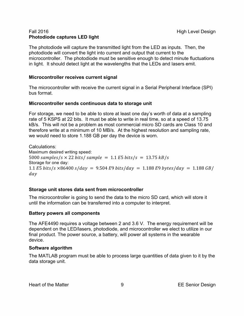
Photodiode captures LED light
The photodiode will capture the transmitted light from the LED as inputs. Then, the photodiode will convert the light into current and output that current to the microcontroller. The photodiode must be sensitive enough to detect minute fluctuations in light. It should detect light at the wavelengths that the LEDs and lasers emit. Microcontroller receives current signal
The microcontroller with receive the current signal in a Serial Peripheral Interface (SPI) bus format.
Microcontroller sends continuous data to storage unit
For storage, we need to be able to store at least one day’s worth of data at a sampling rate of 5 KSPS at 22 bits. It must be able to write in real time, so at a speed of 13.75 kB/s. This will not be a problem as most commercial micro SD cards are Class 10 and therefore write at a minimum of 10 MB/s. At the highest resolution and sampling rate, we would need to store 1.188 GB per day the device is worn. Calculations: Maximum desired writing speed: 5000 𝑠𝑎𝑚𝑝𝑙𝑒𝑠/𝑠 × 22 𝑏𝑖𝑡𝑠/ 𝑠𝑎𝑚𝑝𝑙𝑒 = 1.1 𝐸5 𝑏𝑖𝑡𝑠/𝑠 = 13.75 𝑘𝐵/𝑠 Storage for one day: 1.1 𝐸5 𝑏𝑖𝑡𝑠/𝑠 ×86400 𝑠/𝑑𝑎𝑦 = 9.504 𝐸9 𝑏𝑖𝑡𝑠/𝑑𝑎𝑦 = 1.188 𝐸9 𝑏𝑦𝑡𝑒𝑠/𝑑𝑎𝑦 = 1.188 𝐺𝐵/𝑑𝑎𝑦
Storage unit stores data sent from microcontroller The microcontroller is going to send the data to the micro SD card, which will store it until the information can be transferred into a computer to interpret.
Battery powers all components
The AFE4490 requires a voltage between 2 and 3.6 V. The energy requirement will be dependent on the LED/lasers, photodiode, and microcontroller we elect to utilize in our final product. The power source, a battery, will power all systems in the wearable device. Software algorithm The MATLAB program must be able to process large quantities of data given to it by the data storage unit.

Fall 2016 High Level Design
Heart of the Matter 10 EE Senior Design
Software user interface The user interface should convey to the user any abnormal findings and encourage further medical testing. The program will graphically display the data for the user.
4.3 Future Enhancement Requirements
The following would be enhancements to a more advanced product: ● Wi-Fi/Bluetooth capabilities so data and transmit directly to a computer ● Mobile app (which would go hand-in-hand with Wi-Fi/Bluetooth) to view data from
the device “live”
5 High Level Design Decisions
Microcontroller dictates LED flashing rates
We will be using the microchip PIC32 microcontroller that communicates with the AFE4490 via an SPI interface in order to control the LED current and flashing rates for the two LEDs. We will use the PIC32MX695F512H, the same microcontroller used in class, because it operates from 2-3.6 V, which is the same voltage range as our chip. Additionally, it can communicate via SPI, which we will also use with the AFE4490 chip.
Photodiode captures LED light
The photodiode will need to be able to capture the light from the two LEDs, probably red and infrared, with high efficiency so that the device can give accurate representation of the pulse and oxygenation levels.
Sensor receives current signal The AFE4490 will receive the analog current signal from the photodiode. It will then perform the analog-to-digital conversion in order to pass the data to the microcontroller. Microcontroller sends continuous data to storage unit
The current signal data that the microcontroller receives is then transmitted onto the storage unit. The storage unit will be a micro SD card with 32GB capacity so that it can record data up to at least one month since, as calculated above, the device would need approximately 1.188GB per day when running at the highest resolution and sampling rate. Battery powers all components
For initial testing, we will utilize a USB port and cable to power our device. Once we have progressed further in the design, we will use a battery. The size and power of the

Fall 2016 High Level Design
Heart of the Matter 11 EE Senior Design
battery will be dependent on the final choice of LEDs and the length of time we will be recording data for, while staying within the weight limit for the wearable device. Software and user interface The software algorithm will take the data and turn it into useful information that we can use to create graphs and other information for our GUI. The program will allow the user to choose what he/she wants to see, including graphs of the heart pulse and oxygenation levels. It will also have warnings if any abnormalities are found in the data so that the user knows whether he/she needs further testing. Software user interface
6 Open Questions
General List ● LED/laser types
○ In addition to IR LED (850 nm), should we use a red LED or a green LED? ○ Should we use an LED laser and/or standard propagation LED? ○ How will the body absorb these different wavelengths?
● Body part options ○ Wrist, ear, finger, or waistband? ○ How much light will pass through each part? ○ We will need enough light to pass through the body parts so that we can
extract a signal ● Battery for powering the device wirelessly
○ What battery should we use to power the device? ○ We will need to experiment to see how much power each component
requires. We think it is in our best interest to build the device first and get it working while connected to a computer with a USB connection. Then, we will determine the voltage needed from a battery to support all of the parts.
● LEDs/photodiode spacing ○ How far apart should the LEDs be from each other? ○ How far apart should the LEDs be from the photodiode?
■ This will have to be adjusted based on what body part we choose. ● Signal Amplification
○ How can we amplify the signal after the light is captured from the photodiode?
7 Major Component Costs
Specify the costs of your major system components. This should allow you to have a rough cost estimate of your system. This should include any specialized equipment necessary to demonstrate your project.

Fall 2016 High Level Design
Heart of the Matter 12 EE Senior Design
● Chip ($10)
○ TI AFE4490 ● LEDs
○ Standard red LED ($2) and laser ($12) ● Micro SD card for data storage (32GB $10) ● Battery ($2) ● Microcontroller (free) ● Photodiode ($2) ● Evaluation board ($150)
○ TI board that evaluates AFE4490 ● Wearable mechanism
○ Plastic ○ This will depend on where we place the device
8 Conclusions
Even though photoplethysmography is not the most accurate way of checking whether someone has cardiomyopathy, it is a quick and noninvasive way to point to larger problems because it can be used to find abnormalities in pulse rate and oxygenation levels. This is technology that is used in hospitals and, to a certain extent, in a lot of new wearable technology, but isn’t used to its full capacity either because it is only used for a short period of time or is not processing the data to look for certain abnormalities. Our device would make it possible to find those abnormalities by getting data at a high sampling rate over extended periods of time and would alert the user if he or she should get further testing.

Fall 2016 High Level Design
Heart of the Matter 13 EE Senior Design
References http://www.ti.com/product/AFE4490 PIC32MX695F512H Spec Sheet


