Healthy Harbors, Restored Rivers - csu.edu
70
Healthy Harbors, Restored Rivers A Community Guide to Cleaning Up Our Waterways SIERRA CLUB GREAT LAKES PROGRAM June 2001
Transcript of Healthy Harbors, Restored Rivers - csu.edu

HealthyHarbors,
RestoredRivers
A Community Guide to Cleaning Up Our Waterways
SIERRA CLUB GREAT LAKES PROGRAM
June 2001

Jennifer Feyerherm
Craig Wardlaw,
Headwater Environmental
Services Corporation
Authors
Geoffrey Tichenor
Editor
Sierra Club Great Lakes Ecoregion ProgramEmily Green, Director214 North Henry Street, Suite 203Madison, Wisconsin 53703(608) 257-4994www.sierraclub.orgwww.sierraclub-glp.org
HealthyHarbors,
RestoredRivers

Sediment Cleanups Relevant to theHudson River. Geoffrey Tichenorprovided countless hours of editori-al and general support services.Special thanks go to Emily Greenfor her guidance, support, andoverarching contributions, ScottCieniawski from US EPA GreatLakes National Program Office andJosh Cleland from ICF Incorporatedfor their expertise and review.Additional thanks go to RobertPaulson from WisconsinDepartment of Natural Resourcesand Jan Miller from the ArmyCorps of Engineers for their techni-cal help, Amy Shenot for editorialhelp and moral support, BillFeyerherm for computer wrangling,Sandy Welander for research sup-port, Erin Burg for her bibliographi-cal skills and loose ends manage-ment, and Lindsay Riesch forreview. And thanks (as always) toJudy Hofrichter and Eric Uram.
This document was funded by agenerous grant from the JoyceFoundation.
First Edition, 2001.
Cover photograph by RandallMcCune, courtesy of the MichiganTravel Bureau.
Additional copies are available.Please contact the Sierra Club’sMidwest office at 214 N. Henry St.Suite 203, Madison, Wisconsin,53703.
Printed on 100% recycled, non-chlorine paper with soy-based inks.
The Sierra Club is a non-profit,member-supported, publicinterest organization that pro-
motes conservation of the naturalenvironment by influencing publicpolicy decisions—legislative, admin-istrative, legal, and electoral. TheClub celebrated its centennial in 1992and has over 700,000 members.
Statement of Purpose: to explore,enjoy, and protect the wild placesof the earth, to practice and pro-mote the responsible use of theearth’s ecosystems and resources;to educate and enlist humanity toprotect and restore the quality ofthe natural and human environ-ment; and to use all lawful meansto carry out these objectives.
The Sierra Club’s Great LakesEcoregion Program works to turnback specific threats to the region.Based in Madison, Wisconsin, theProgram has coordinated efforts forover twenty-five years to protectthe Great Lakes from air, water, andland pollution. Regional activistsemploy an ecosystem approach toaddress environmental problems inthe Great Lakes Basin.
Acknowledgements
This booklet reflects the hard workand ideas from organizationsaround the Great Lakes Basin andbeyond. It is based on A Citizen’sGuide: Cleaning Up ContaminatedSediment, released by the LakeMichigan Federation in 1989. It alsodraws heavily from two ScenicHudson publications: Advances inDredging Contaminated Sedimentand Results of Contaminated
about the sierra club

Getting Started . . . . . . . . . . . . . . . . . . . . . . . . . . . . . . . . . . . . . . . . . . . . . . 1
How It Happened . . . . . . . . . . . . . . . . . . . . . . . . . . . . . . . . . . . . . . . . . . . . 2
The Problem . . . . . . . . . . . . . . . . . . . . . . . . . . . . . . . . . . . . . . . . . . . . . . . . 3
The Solution . . . . . . . . . . . . . . . . . . . . . . . . . . . . . . . . . . . . . . . . . . . . . . . . 6
How Sediment Cleanup Usually Works . . . . . . . . . . . . . . . . . . . . . . . . . . . 7
Weighing the Options – Criteria for Choosing a Cleanup Strategy . . . . . . 9
Considering the Consequences . . . . . . . . . . . . . . . . . . . . . . . . . . . . . . . . 10
Leaving Them There . . . . . . . . . . . . . . . . . . . . . . . . . . . . . . . . . . . . . . . . 12
Natural Recovery . . . . . . . . . . . . . . . . . . . . . . . . . . . . . . . . . . . . . . . . 12
Capping . . . . . . . . . . . . . . . . . . . . . . . . . . . . . . . . . . . . . . . . . . . . . . . . 14
Treating It in Place . . . . . . . . . . . . . . . . . . . . . . . . . . . . . . . . . . . . . . . 16
Digging Them Up . . . . . . . . . . . . . . . . . . . . . . . . . . . . . . . . . . . . . . . . . . . 17
Choosing a Dredge . . . . . . . . . . . . . . . . . . . . . . . . . . . . . . . . . . . . . . . 18
Types of Dredges . . . . . . . . . . . . . . . . . . . . . . . . . . . . . . . . . . . . . . . . 20
Digging It Up: Mechanical Dredges . . . . . . . . . . . . . . . . . . . . . . . . 20
Enclosed Bucket Dredge and Cable Arm Dredge
Sucking It Up: Hydraulic and Pneumatic Dredges . . . . . . . . . . . . . 22
Cutterhead Dredge
Portable Hydraulic Dredge
Plain Suction Head Dredge
Horizontal Auger Dredge
Screw Impeller Dredge
Eddy Pump
Oozer Pump
Pneuma Pump
Airlift Dredge
Amphibex Dredge
Waterless Dredge
Wide Sweeper Cutterless Dredge
Clean-up Dredge
Matchbox Dredge
Refresher System
Disposal Options . . . . . . . . . . . . . . . . . . . . . . . . . . . . . . . . . . . . . . . . . . . 30
Confined Disposal Facilities (CDFs) . . . . . . . . . . . . . . . . . . . . . . . . . . 30
Upland Landfills . . . . . . . . . . . . . . . . . . . . . . . . . . . . . . . . . . . . . . . . . 32
Beneficial Reuse . . . . . . . . . . . . . . . . . . . . . . . . . . . . . . . . . . . . . . . . . 32
table of contents

Treatment Options . . . . . . . . . . . . . . . . . . . . . . . . . . . . . . . . . . . . . . . . . . 33
Discovering Sediment Characteristics and Testing Technologies . . . 34
Just in Case: Safety Features . . . . . . . . . . . . . . . . . . . . . . . . . . . . . . 35
Pre-treatment Technologies . . . . . . . . . . . . . . . . . . . . . . . . . . . . . . . . . . . 36
Dewatering . . . . . . . . . . . . . . . . . . . . . . . . . . . . . . . . . . . . . . . . . . . . . 37
Separation Techniques . . . . . . . . . . . . . . . . . . . . . . . . . . . . . . . . . . . . 37
Size separation . . . . . . . . . . . . . . . . . . . . . . . . . . . . . . . . . . . . . . . . 37
Density separation . . . . . . . . . . . . . . . . . . . . . . . . . . . . . . . . . . . . . 38
Magnetic separation . . . . . . . . . . . . . . . . . . . . . . . . . . . . . . . . . . . . 38
Water Treatment . . . . . . . . . . . . . . . . . . . . . . . . . . . . . . . . . . . . . . . . . 39
Soil Washing . . . . . . . . . . . . . . . . . . . . . . . . . . . . . . . . . . . . . . . . . . . . 39
Treatment Technologies . . . . . . . . . . . . . . . . . . . . . . . . . . . . . . . . . . . . . . 41
Biological Treatment . . . . . . . . . . . . . . . . . . . . . . . . . . . . . . . . . . . . . . 41
Solid Phase Systems . . . . . . . . . . . . . . . . . . . . . . . . . . . . . . . . . . . . 42
Bioslurry Systems . . . . . . . . . . . . . . . . . . . . . . . . . . . . . . . . . . . . . . 42
Phytoremediation . . . . . . . . . . . . . . . . . . . . . . . . . . . . . . . . . . . . . . . . 44
Metal Extraction . . . . . . . . . . . . . . . . . . . . . . . . . . . . . . . . . . . . . . . . . 45
Leaching . . . . . . . . . . . . . . . . . . . . . . . . . . . . . . . . . . . . . . . . . . . . . 46
Flotation . . . . . . . . . . . . . . . . . . . . . . . . . . . . . . . . . . . . . . . . . . . . . 46
Electrokinetics and Sonic Mixing . . . . . . . . . . . . . . . . . . . . . . . . . . 46
Chemical Treatment of Organics . . . . . . . . . . . . . . . . . . . . . . . . . . . . 47
Extractive Technologies . . . . . . . . . . . . . . . . . . . . . . . . . . . . . . . . . 48
Reactive Technologies . . . . . . . . . . . . . . . . . . . . . . . . . . . . . . . . . . 48
Thermal Treatment . . . . . . . . . . . . . . . . . . . . . . . . . . . . . . . . . . . . . . . 49
Thermal Desorption . . . . . . . . . . . . . . . . . . . . . . . . . . . . . . . . . . . . 49
Incineration . . . . . . . . . . . . . . . . . . . . . . . . . . . . . . . . . . . . . . . . . . . 51
Thermal Reduction . . . . . . . . . . . . . . . . . . . . . . . . . . . . . . . . . . . . . 52
Vitrification . . . . . . . . . . . . . . . . . . . . . . . . . . . . . . . . . . . . . . . . . . . 53
Immobilization by Fixation or Solidification . . . . . . . . . . . . . . . . . . . 55
Moving Forward . . . . . . . . . . . . . . . . . . . . . . . . . . . . . . . . . . . . . . . . . . . . 57
Appendix A: Roadmap to Remediation . . . . . . . . . . . . . . . . . . . . . . . . . . 58
Appendix B: Where can I find the information I need? . . . . . . . . . . . . . . 59
Appendix C: Glossary . . . . . . . . . . . . . . . . . . . . . . . . . . . . . . . . . . . . . . . . 60
Appendix D: Additional Resources . . . . . . . . . . . . . . . . . . . . . . . . . . . . . 62
References . . . . . . . . . . . . . . . . . . . . . . . . . . . . . . . . . . . . . . . . . . . . . . . . 63

The Great Lakes are the crown jewels of the Midwest
and a natural treasure of worldwide importance. Their
crystalline waters support a wealth of life, including
species found nowhere else and more than 35 million
people who call this area home. They hold one-fifth of
the world’s fresh surface water and provide drinking
water to the majority of people who live around their
shores. They are central to the region’s manufacturing
economy, in addition to being a major source of recre-
ation and tourism dollars. They are the region’s eco-
nomic, ecological, and spiritual lifeblood. They deserve
protection.
Though the lakes look clean and clear from years of
improving water quality, decades of development and
industrialization have left their mark in the form of
reservoirs of toxic sediments. While the pollution itself
can’t be seen, its impacts on the environment, people,
and economy are clear. We have many of the tools and
much of the knowledge to clean up this toxic legacy.
However, generating the will, the resources, and the
community involvement needed to take action remains
one of our greatest challenges. This guide is designed
to help engage communities by laying out a roadmap
for cleanup success and providing information on how
we can move forward. We hope that community
involvement will help society generate the will to take
action. By taking action, we can leave our children with
water safe for fishing and swimming as well as a
vibrant, sustainable economy based on something
more valuable than gold – clean, clear water.
getting started
MICHIGAN TRAVEL BUREAU

Until about 150 years ago,sediments entered the GreatLakes very slowly. Moving
water pried particles of clay, silt,and sand from matted plant rootsand washed them downhill intostreams, where more water carriedthem to river mouths and the lakesbeyond. When the water sloweddown, the particles dropped out,sank to the bottom, and becamesediments.
Settlement and industrialization ofthe Great Lakes Basin changed thisnatural process in two ways. First,by clearing vast areas for farmingand development, we brokethrough the matted net of rootsthat held soils in place, allowingwater to wash them downstreammuch more quickly. Second, rapidindustrialization and increasing useof pesticides and other chemicalsreleased a toxic cocktail of pollu-tants from industrial smokestacksand runoff from roads and fields.Rain and river water mixed thesepoisons with the soils and carriedthem downstream. Most of thepoisons settled out with the sedi-ments at the bottoms of our rivers,harbors, and bays. The poisonshave been pouring out of dischargepipes and sewers, leaching fromhazardous waste dumps, and evenraining from the sky long enoughto have built up dangerous levels inthe sediments of many areasaround the Great Lakes. Theprocess continues today.
how it happened...
Pollutants come from many sources and cycle throughout the ecosystem.
NA
TIO
NA
L PA
RK
SE
RV
ICE
AG
ENS
KY
AN
D C
OM
PAN
Y, TOR
ON
TO, C
AN
AD
A; M
OD
IFIED B
Y D
ESIG
N &
ILLUS
TRA
TION
INC
., KA
LAM
AZO
O, M
I.

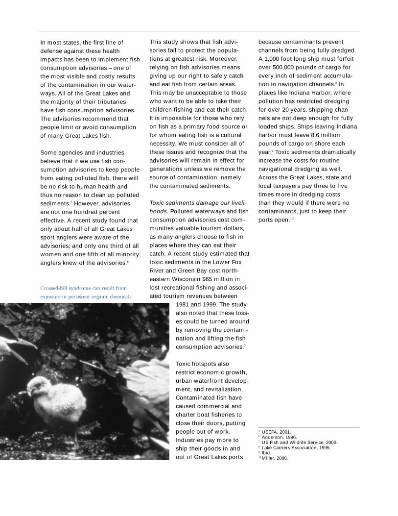
times more likely to have chickswith crossed bills as birds nestingin less polluted surroundings.2
Mink experience reproductive failurewhen they eat fish containing aslittle as 0.3 to 5 ppm (parts permillion) PCBs, levels commonlyfound in Great Lakes fish.3 Fish insome rivers have much higher thanaverage rates of tumors, becauseof pollutants in the sediments.Some of the most polluted sites,like Indiana Harbor, are almost bar-ren – few species of fish and otherorganisms are able to survive thepoisons in the sediments.
Toxic sediments threaten ourhealth. Poisons build up in our ownbodies when we eat fish from theGreat Lakes, just like they do in thebodies of bald eagles. Cancer,developmental problems, immunedisorders, learning difficulties anddisabilities, reproductive problems,and neurological disorders can allbe caused by consuming fish lacedwith chemicals found in sedimentsaround the Great Lakes.4 Thosemost at risk are often least aware ofthe problem or unable to shift to a
different source offood. These peopleinclude expectantmothers, developingchildren, people whorely on self-caughtfish as a major foodsource, and thosewith cultural ties toeating fish.
The governments of theUnited States and Canadaidentified 42 areas around
the Great Lakes, termed Areas ofConcern or AOCs, that have signifi-cant pollution problems. All ofthem suffer the effects of pollutedsediments – a toxic legacy thatthreatens our environment, health,and livelihoods.
Toxic sediments damage our envi-ronment. Polluted sediments posethe greatest risk to fish-eating birdsand wildlife. Polluted sedimentsmay not kill most fish, birds, or ani-mals, but they can cause birthdefects, reproductive failure, andother problems that make long-term survival difficult. For example,studies show that bald eagles livingon the shores of the Great Lakeshave a significantly lower rate ofreproductive success than baldeagles living near inland waters.Double-crested cormorants nestingnear the polluted waters of GreenBay are twice as likely to lay eggswith deformed embryos and forty
Just as the rushing waters accumu-late more poisons as they movedownstream, poisons also accumu-late in the bodies of animals asthey move up the food chain. Toxicsediments provide homes and foodfor plants and creatures – if theydon’t kill them first. Laboratorytests show that contaminated sedi-ments can be lethal to small crus-taceans and insect larvae.1 Thoughsmall and inconspicuous, thesecreatures occupy a strategic posi-tion at the base of aquatic foodchains. The organisms that surviveexposure to toxic sediments retainsome of the toxic chemicals in theirbodies. Many chemicals, like heavymetals, PCBs, and other organiccompounds, bind themselves to fator muscle tissues. When smallerorganisms are eaten by largerorganisms, the chemicals buildup or biomagnify. Animals at thetop of the food chain, like trout,mink, bald eagles, and people,store more of the chemicals intheir bodies each time they eat acontaminated meal.
...the problem
1 Landrum, et. al. 1999.2 Colborn, et. al. 1996.3 Aulerich, et. al. 1977.4 Colborn, et. al. 1996; Greater Boston Physicians for Social Responsibility, 2000;US Department of Health and Human Services, 2000.
BILL STAPP EPA, GREAT LAKES NATIONAL PROGRAM OFFICE

The Poisons
The pollutants that place our environment, health, and livelihoods at risk fall into six categories: nutrients, bulk organics,metals, halogenated hydrocarbons or persistent organics, polycyclic aromatic hydrocarbons, and pesticides.
All of these poisons can take several forms. Some are dissolved or suspended in the water,while others chemically bind to mineral particles or decaying matter that make up sediments.The amount of contaminants that sediments can hold depends chiefly on two characteristics: theaverage size of the sediment particles and the amount of organic matter in the sediments. Fine(tiny) particles, clay, and fine silts can hold more contaminants than coarser sands and gravelsbecause the smaller particles provide far more surface area per unit volume to which contami-nants can bind. Many contaminants also bind more easily to organic substances than to inertinorganic matter.
• Nutrientsinclude com-pounds of nitro-gen (ammoniaamong them)and phospho-rous. In smallamounts, thesenutrients areessential to life.In largeramounts, theycause explosionsof algae growthand are toxic to fish.
• Bulk organicsare a class ofhydrocarbons(chemicals thatcontain only car-bon and hydro-gen) and includethings like oiland grease.Bacteria thatbreak down bulk organicsmay use up theoxygen neces-sary to maintainaquatic life.
• Metals likechromium, manganese,lead, cadmium,and mercury canbe toxic toplants, animals,and humanbeings.
• Halogenatedhydrocarbons, or persistentorganics, get their name fromthe fact that eachmolecule includes a halogen (chlorine,bromine, fluorine,iodine, or astatine).They are persistentbecause as verystable compounds,they are resistant to decay. Many are highly toxic,such as PCBs and dioxins.
• Polycyclic aromatic hydro-carbons, orPAHs, are agroup of organicchemicals thatincludes severalpetroleum prod-ucts andbyproducts.Among theseare naphthalene,used to makemothballs, andpyrene whichcauses cancer in fish.
• Pesticides,such as DDT,often persist in the environ-ment for longperiods of time.Many, but notall, pesticides also fit in one of the above categories.
EPA
, GR
EA
T L
AK
ES
NA
TIO
NA
L P
RO
GR
AM
OFF
ICE
because contaminants preventchannels from being fully dredged.A 1,000 foot long ship must forfeitover 500,000 pounds of cargo forevery inch of sediment accumula-tion in navigation channels.8 Inplaces like Indiana Harbor, wherepollution has restricted dredgingfor over 20 years, shipping chan-nels are not deep enough for fullyloaded ships. Ships leaving Indianaharbor must leave 8.6 millionpounds of cargo on shore eachyear.9 Toxic sediments dramaticallyincrease the costs for routine navigational dredging as well.Across the Great Lakes, state andlocal taxpayers pay three to fivetimes more in dredging costs than they would if there were nocontaminants, just to keep theirports open.10
5 USEPA, 2001.6 Anderson, 1996.7 US Fish and Wildlife Service, 2000.8 Lake Carriers Association, 1995.9 Ibid.10 Miller, 2000.
This study shows that fish advi-sories fail to protect the popula-tions at greatest risk. Moreover,relying on fish advisories meansgiving up our right to safely catchand eat fish from certain areas. This may be unacceptable to thosewho want to be able to take theirchildren fishing and eat their catch.It is impossible for those who relyon fish as a primary food source orfor whom eating fish is a culturalnecessity. We must consider all ofthese issues and recognize that theadvisories will remain in effect forgenerations unless we remove thesource of contamination, namelythe contaminated sediments.
Toxic sediments damage our liveli-hoods. Polluted waterways and fishconsumption advisories cost com-munities valuable tourism dollars,as many anglers choose to fish inplaces where they can eat theircatch. A recent study estimated thattoxic sediments in the Lower FoxRiver and Green Bay cost north-eastern Wisconsin $65 million inlost recreational fishing and associ-ated tourism revenues between
1981 and 1999. The studyalso noted that these loss-es could be turned aroundby removing the contami-nation and lifting the fishconsumption advisories.7
Toxic hotspots alsorestrict economic growth,urban waterfront develop-ment, and revitalization.Contaminated fish havecaused commercial andcharter boat fisheries toclose their doors, puttingpeople out of work.Industries pay more toship their goods in andout of Great Lakes ports
In most states, the first line ofdefense against these healthimpacts has been to implement fishconsumption advisories – one ofthe most visible and costly resultsof the contamination in our water-ways. All of the Great Lakes andthe majority of their tributarieshave fish consumption advisories.The advisories recommend thatpeople limit or avoid consumptionof many Great Lakes fish.
Some agencies and industriesbelieve that if we use fish con-sumption advisories to keep peoplefrom eating polluted fish, there willbe no risk to human health andthus no reason to clean up pollutedsediments.5 However, advisoriesare not one hundred percent effective. A recent study found thatonly about half of all Great Lakessport anglers were aware of theadvisories; and only one third of allwomen and one fifth of all minorityanglers knew of the advisories.6
Crossed-bill syndrome can result from
exposure to persistent organic chemicals.

all of the major techniques andtechnologies available for sedimentcleanup, touching on the pros andcons of each.
The guide is designed to serve as aresource for citizens who are evalu-ating or developing cleanup plansfor sediment sites. It raises ques-tions that people should ask abouteach cleanup strategy and presentsthe range of solutions available toaddress polluted sediment sites.We hope that this guide will helpdemystify sediment cleanup andwill make it clear that there aresolutions to this complex problem.
We do not have to livewith this toxic legacy.We have the tools and
the knowledge to clean up thesetoxic sites. We can leave our chil-dren with water that is safe for fish-ing and swimming and with har-bors that promote economicgrowth. Now we must generate thewill to take action. This guide pro-vides information to help get theball rolling.
This guide describes the tools andtechniques that can be used toclean up sites with polluted sedi-ment. It begins with an overview ofthe cleanup process, the opportuni-ties for citizen input, and the broad-er issues that must be factored intoany cleanup plan. It then discusses
the solutionJI
M G
RIN
DR
OD
require much longer periods oftime to be effective and are notnecessarily permanent fixes to theproblem. The specific tradeoffsassociated with each sedimentmanagement option, as well as the broader, overarching issuesdescribed below, should be consid-ered as part of any “risk manage-ment decision” involving pollutedsediments.
ment management or cleanupgoals and the tradeoffs associatedwith various options. In general,the more active cleanup optionswill meet site cleanup goals morequickly and permanently, but theycost more than low-effort strategiesand can require the control or dis-posal of wastes. The lowest costoptions may ultimately meetcleanup goals, but they often
The cleanup process beginswith the identification of asite-specific problem, such as
tumors on fish or a lack of commonbottom-dwelling animals. The firststep is to broadly assess the extentof the problem and determine itscause and impacts. More specificevaluations follow in the form of asite assessment and a risk assess-ment. Site assessment involvesextensive sampling to determinethe location of the contamination,the nature of the contaminants, thephysical characteristics of the siteand the sediments, and the impactsof things like water flow, boat traffic,and animals on the site. Riskassessment evaluates the exposureof both humans and wildlife to pol-lutants, as well as the potential forsubsequent health impacts.
After collecting information aboutthe site and the problem, the com-munity at large and environmentalagencies must decide what thegoals for the site should be.Agencies usually consider this tobe a risk management decision, ordefining the “acceptable level ofrisk”. For communities, this meansdeciding what to protect and howquickly to protect it. For example, acommunity might have to decidewhether the goal is to clean up thefish so that people can safely eatthem or to rehabilitate the minkpopulation. Then they must decidewhether they should achieve thegoal in 10, 20, or 100 years.
This guide is designed to helpinform these decisions by explain-ing the options for meeting sedi-
how sediment cleanup usually works
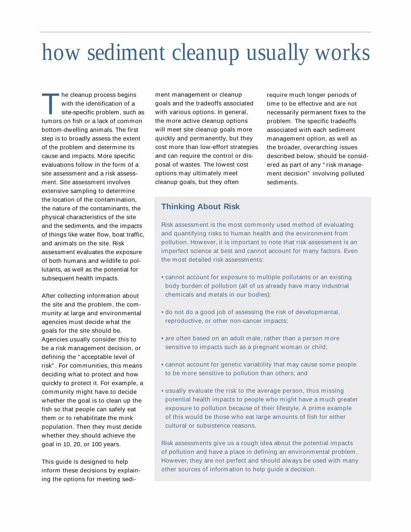
Thinking About Risk
Risk assessment is the most commonly used method of evaluatingand quantifying risks to human health and the environment frompollution. However, it is important to note that risk assessment is animperfect science at best and cannot account for many factors. Eventhe most detailed risk assessments:
• cannot account for exposure to multiple pollutants or an existingbody burden of pollution (all of us already have many industrialchemicals and metals in our bodies);
• do not do a good job of assessing the risk of developmental,reproductive, or other non-cancer impacts;
• are often based on an adult male, rather than a person moresensitive to impacts such as a pregnant woman or child;
• cannot account for genetic variability that may cause some peopleto be more sensitive to pollution than others; and
• usually evaluate the risk to the average person, thus missingpotential health impacts to people who might have a much greaterexposure to pollution because of their lifestyle. A prime exampleof this would be those who eat large amounts of fish for eithercultural or subsistence reasons.
Risk assessments give us a rough idea about the potential impactsof pollution and have a place in defining an environmental problem.However, they are not perfect and should always be used with manyother sources of information to help guide a decision.

Community Involvement: A Must
Community members should be involved in cleanup decisions fromthe outset of the cleanup process. After all, it is community membersthemselves who live, work and play near polluted waters and whosechildren will live with the results of cleanup decisions made today.Communities should not let special interests call the shots. Instead,community members should bring their real world concerns andissues to the table. Without community input, it is all too easy fordecision-makers to make cleanup decisions based primarily on cost orease of implementation. Members of the general public can provide avery different perspective, particularly on questions such as how long
we should wait for risks to humanhealth and the environment todecline.
Unfortunately, the level of publicinvolvement varies from site tosite and is usually dependent onthe extent to which the agenciesor industries in charge of thecleanup have sought citizen input.In an effort to increase communityparticipation in sediment cleanups,the Sierra Club and Lake MichiganFederation developed a modelpublic involvement plan thatagencies or industries can applyto any cleanup effort. The planis available from both organiza-tions11 and can also be found atwww.sierraclub-glp.org. However,
even at sites where extensive public participa-tion may not be a high priority, we hope that thisguide will provide community members with theinformation needed to weigh cleanup options,make informed decisions, and get involved.
11 For copies of the report, contact either SierraClub Midwest Office, 214 N. Henry St., Madison,WI, 53703, (608) 257-4994 or Lake MichiganFederation, 700 Washington Ave., Suite 150,Grand Haven, MI, 49417, (616) 850-0745.
COPYRIGHT 2000 DAVID-LORNE PHOTOGRAPHIC
CARL ZICHELLA, SIERRA CLUB

There are basically twooptions for contaminatedsediments: leave them
there or dig them up.
Leaving them there either meansdoing nothing and hoping that thewaterbody’s natural processes willcover the poisons, or trying to con-tain the contaminants in place andprevent them from entering theecosystem. Options for leavingtoxic sediments in place includenatural recovery, capping, biologi-cal and chemical treatment.
Digging them up (dredging them)removes toxic sediments from theaquatic environment relatively quick-ly and allows the ecosystem torecover without the presence of poi-sons. This guide will describe sever-al kinds of dredges and ways to dis-pose of or treat dredged sediments.
There is no one-size-fits-all solutionto sediment problems; sites willoften require a mix of cleanupoptions to most effectively addressthe problem. Some of the criteria toconsider when choosing cleanupoptions include:
Site conditions – Sediment andwater characteristics can limit theoptions for any given site, particu-larly when considering leaving con-taminants in place. This is not aviable option where strong cur-rents, boat traffic, or other condi-tions wash pollutants downstream.However, dredges and treatmenttechnologies are available that canaddress most site conditions.
weighing the options—criteria forchoosing a cleanup strategy
Type of contaminant(s) – Sometreatment methods only work wellfor specific contaminants.
Extent of contamination – Someoptions are better for bigger sites,some for smaller.
Risks to humans and the environ-ment – Both short- and long-termrisks must be considered whenchoosing an option. If left in thewaterbody, contaminants poselong-term risks to human healthand the environment. While somecleanup options may disrupt theaquatic environment in the short-term, they can generally eliminatethe long-term risks posed by in-place pollution.
Cleanup goals – Removing contam-inants from the aquatic ecosystemwill generally meet cleanup goalsmore quickly and with greater per-manence than other options. Thespeed and desired level of cleanupmay eliminate some options.
Costs – While cleanup can beexpensive, it is important to recog-nize that cleaning up a waterbodycan result in many economic bene-fits for the local community andindustries, such as increasedtourism, recreation and fishing, lessexpensive port maintenance, water-front redevelopment, and elimina-tion of fish consumption advisories.
WI DEPARTMENT OF NATURAL RESOURCES

less invasive cleanup option.However, these arguments ignorethe fact that whatever disruptionsdredging may cause are relativelyshort-lived, while there may bevery long-term impacts to humanhealth or the environment fromleaving the pollutants in place. Inaddition, removing pollutants fromthe ecosystem via dredging willlikely achieve the site cleanup goalsmuch more quickly than less inten-sive cleanup options. The bottomline is that the impacts of in-placepollutants must be compared to thebenefits of their absence from theecosystem into the future, for aslong as it would take to reach thesite cleanup goals under eitheroption. In many areas, this meanslooking out well over 100 years ifpollutants are left in place. Thistype of analysis makes a strongcase for spending money now toavoid leaving this problem for ourchildren and grandchildren.
Another factor to consider is thelong-term predictability and perma-nence of any cleanup solution. It isvery difficult to predict the long-term fate of pollutants in the envi-ronment, particularly in an activeriver system or harbor. If left inplace or covered by a cap, there isalways a possibility of the pollu-tants being disturbed by natural orhuman forces. Storms, floodevents, ice scour, and organismsburrowing into the sediments canstir up pollutants, as can boat traf-fic, navigational dredging, riverchannelization, and dam removal.For example:
In addition to sitespecific criteria,there are overar-
ching issues thatneed to be consid-ered when choosinga sediment manage-ment strategy.
Some of these issues tend to begiven short shrift, perhaps becausethe impacts would be felt in thelong-term, or far downstream, orby parties not otherwise involved inthe cleanup. Because they are notoften discussed in detail, we’veprovided some additional informa-tion on these issues below.
Looking at the big picture
and over the long-term:
Industries often argue that the costand negative impacts of dredgingshould preclude its use in favor of a
considering the consequences
Indiana Harbor (above).
EPA, GREAT LAKES NATIONAL PROGRAM OFFICE
EP
A, G
RE
AT
LA
KE
S N
AT
ION
AL
PR
OG
RA
M O
FFIC
E

Financial impacts on
other parties:
Finally, as previously noted, pollut-ed sediments and a contaminatedwaterway can impose substantialcosts on industries and the localeconomy. However, most of thecompanies who have to pay highercosts or who lose business becauseof the pollution are not the samecompanies who caused the prob-lem in the first place. Thus, theindustry responsible for the pollu-tion does not often have a direct,economic interest in its cleanup.In addition, some of the costsimposed on others by contamina-tion are relatively difficult to meas-ure. This can lead to a disparity inwhich the cost of implementing thecleanup itself seems to be givengreater weight in a cleanup deci-sion than the costs imposed onother businesses by the pollution.
All of these things are broadissues that communities shouldconsider when trying to findsolutions to a polluted sedimentproblem. However, it is critical tounderstand the technical meritsand tradeoffs associated with eachcleanup technique when evaluatingcleanup options. The remainder ofthis document is dedicated toexplaining, in plain language, thetechnical requirements, effective-ness, costs, special considerations,and pros and cons for each sedi-ment management option, fromnatural recovery to dredging andtreatment.
Ecological impacts on a
broad system:
When pollutants are washed down-stream, they have an impact on abroader ecological system thatmust be considered when selectinga cleanup solution. For example,many Great Lakes contaminatedsediment sites are located in riversor harbors where they leach pollu-tants downstream into the lakesthemselves. The EPA has deter-mined that these sites are a majorsource of fish consumption advi-sories across the lakes. Recentresearch shows that, at least in theGreat Lakes, these pollutants arenot buried once they reach thelakes, but are recycled back into thefood web and even into the atmos-phere.12 The lakes can evaporatesignificant quantities of some per-sistent pollutants like PCBs, addingto a global pool of contaminants.While it is extremely difficult toquantify the contribution of a par-ticular sediment site to this broadproblem, we must be aware thatthere are broader, ecosystem-wideimpacts of pollution – beyond whata risk assessment is able to meas-ure. This is why polluted sedimentsare of concern, even if “nobody iseating the fish”. We should discussthese issues when deciding howquickly to meet cleanup goals orwhether or not to leave pollutantsin place.
• More than 20 years of data forspecific cross sections of the FoxRiver in northeast Wisconsin showthat the river channel has movedback and forth over time as cur-rents change, so that sedimentsmight build up in one area for afew years, only to wash away againa few years later. In some spots,the depth of the riverbed changedby as much as 6 feet over time, assediments alternatively erodedaway and built up. This means thateven if pollutants are currentlyburied, and clean sediment is accu-mulating on top of them, they maylater be exposed as currents shift.
• Fox River monitoring during asediment dredging project showedthat the weekly arrival and depar-ture of a coal boat stirred up signifi-cantly more pollution than thedredge.
• Fox River monitors also revealedmeasurable spikes in pollution lev-els downstream of contaminatedhotspots during and after heavyrain events.
These factors must be consideredwhen deciding how to deal withpolluted sediments. We’ve oftenheard the claim that a river is depo-sitional – that sediments are build-ing up and burying the pollution –so we don’t need to clean it up.While this may be true in someareas, it does not acknowledge thatwe can neither predict nor controlnatural processes over time, andthat we run the risk of having todeal with the pollution tomorrow ifwe leave it in place today.
EPA, GREAT LAKES NATIONAL PROGRAM OFFICE
12 The Delta Institute, 2000.
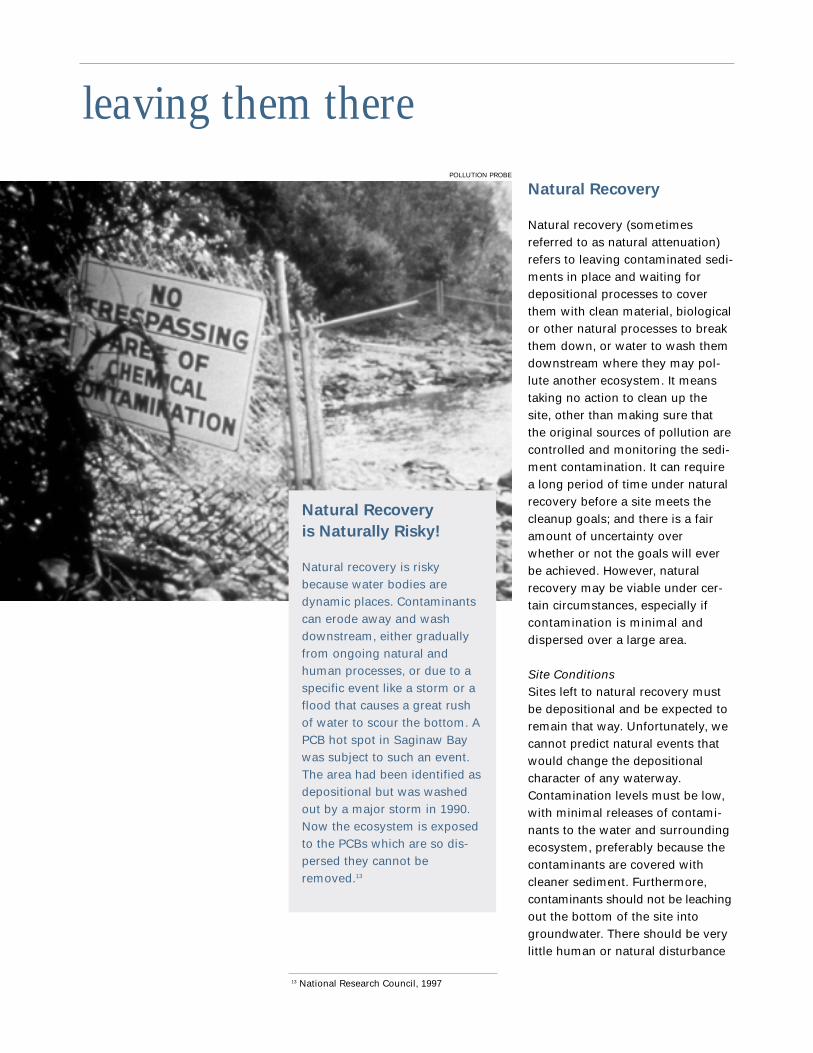
Natural Recovery
Natural recovery (sometimesreferred to as natural attenuation)refers to leaving contaminated sedi-ments in place and waiting fordepositional processes to coverthem with clean material, biologicalor other natural processes to breakthem down, or water to wash themdownstream where they may pol-lute another ecosystem. It meanstaking no action to clean up thesite, other than making sure thatthe original sources of pollution arecontrolled and monitoring the sedi-ment contamination. It can requirea long period of time under naturalrecovery before a site meets thecleanup goals; and there is a fairamount of uncertainty overwhether or not the goals will everbe achieved. However, naturalrecovery may be viable under cer-tain circumstances, especially ifcontamination is minimal anddispersed over a large area.
Site ConditionsSites left to natural recovery mustbe depositional and be expected toremain that way. Unfortunately, wecannot predict natural events thatwould change the depositionalcharacter of any waterway.Contamination levels must be low,with minimal releases of contami-nants to the water and surroundingecosystem, preferably because thecontaminants are covered withcleaner sediment. Furthermore,contaminants should not be leachingout the bottom of the site intogroundwater. There should be verylittle human or natural disturbance
leaving them therePOLLUTION PROBE
Natural Recovery
is Naturally Risky!
Natural recovery is riskybecause water bodies aredynamic places. Contaminantscan erode away and washdownstream, either graduallyfrom ongoing natural andhuman processes, or due to aspecific event like a storm or aflood that causes a great rushof water to scour the bottom. APCB hot spot in Saginaw Baywas subject to such an event.The area had been identified asdepositional but was washedout by a major storm in 1990.Now the ecosystem is exposedto the PCBs which are so dis-persed they cannot beremoved.13
13 National Research Council, 1997

• maintaining and distributing fishadvisories indefinitely,
• increased costs for navigationaldredging,
• lost fishing and tourism revenue,• health effects from continued
exposure to the contaminants, and • funding for other cleanup options
should the site become erosional.
• how deep the contaminant levelsare (i.e. whether the site isremaining depositional),
• how fast the sediments arereleasing chemicals,
• the amount of contaminants thatbottom-dwelling organisms aretaking in,
• the extent that contaminatedorganisms migrate out of the areaor are harvested, and
• how the chemicals change asthey lay in the sediment (“in bedtransformation rates”).14
CostsConcrete costs for natural recoverystrategies include initial site assess-ment and long-term, indefinite mon-itoring. Natural recovery strategiesalso include hidden costs such as:
at the site. The site should not be ina major transportation corridor orbe subject to future dredging.Dams along the waterway pose aspecial risk. Altering a dam in anyway would affect water flows andsubsequently the shape of the riverbottom and banks.
Special ConsiderationsNatural recovery requires ongoingmonitoring to ensure that the siteremains depositional and that pol-lutants continue to be buried. If anyof the measurements indicate thatthe site is starting to erode, otheroptions must be employed.
Monitoring should determine:• how fast sediment is covering the
contaminants,
Pros
• Compared to other options,natural recovery is cheaper upfront.
• Natural recovery does notdisrupt bottom ecosystems.
Cons
• Ecosystem recovery takes along time – in many cases, cen-turies – and there is no guaran-tee of success.
• Natural recovery has been thedefault option for all of theGreat Lakes for more than 30years, yet we still see the nega-tive impacts of contamination.
• Fish consumption advisories,health risks, and other impaireduses of the waterway will per-sist.
• Even if contamination is cov-ered by cleaner sediments,there is still a risk that thecleaner sediments will bewashed away in the future,reintroducing the above prob-lems.
• Natural recovery requireslong-term, indefinite monitoring.
• If the site starts to erode inthe future, it will have to becleaned up using some otheroption.
• Site requirements are so strin-gent that few places are suit-able for natural recovery.
N A T U R A L R E C O V E R Y
Sediment plume from the Maumee River emptying into the western basin of Lake Erie
US
EPA
14 Ibid.

organisms dig into the cap.Contaminants below the cap, espe-cially ammonia and some forms ofnitrogen and phosphorous, canleach upwards. Caps should be atleast as thick as the sum of the dis-tance that pollutants will seepthrough the cap and the distancethat organisms will dig down intoit. In other words, a cap shouldensure that the deepest diggingworm will not reach the highestescaping pollutant.
After a cap is placed, monitoringrequirements almost mirror thoseof natural recovery with a few addi-tions. When monitoring the con-taminant levels in the sediment bydepth, movement of the sedimentor contaminants into the cap layeris important. Monitoring shouldalso track cap depth across thewidth and breadth of the project tocheck for any shifting and assurecap integrity over time.
Capping
Just as it sounds, capping consistsof covering contaminated sedi-ments with clean material. Cappingattempts to create a barrier betweenpoison-laced sediments and theecosystem. The simplest and cheap-est caps are clean sediments, sand,or gravel. Geotextiles, or speciallymade fabrics, and armored capsmade out of cement blocks or otherarmoring materials are more expen-sive cap options. Geotextiles can behard to place and subject to tears,but are specially designed to con-tain contaminants. Though sturdy,armored caps tend to be leakyunless they are combined with geo-textiles. Conventional dredging andconstruction equipment can placethe cap, but they must be controlledwith extreme precision.
Site Conditions The site requirements for cappingare similar to those for natural
recovery. Even though caps createa barrier between contaminantsand the ecosystem, they can erodeor be damaged by storms, boattraffic, anchors, and other distur-bances. For this reason, contamina-tion levels should be low. Thewaterbody must be depositional atthe site of the cap (again, this couldchange over time) with very fewdisturbances to the water or sedi-ments. Navigational traffic shouldbe minimal. The site should neverbe considered for navigationaldredging. Dam modifications signif-icantly change water flow and placeany downstream caps at risk.Finally, the sediments must be firmenough to support the cap, other-wise the capping material can sinkthrough the sediments and leavethem exposed.
Special ConsiderationsCaps must be constructed to with-stand pressures from above andbelow. From above, burrowing
EPA
, GR
EA
T LA
KE
S N
AT
ION
AL P
RO
GR
AM
OFFIC
E
Cap placement

CostsCapping costs include site assess-ment, cap material, placement mon-itoring to ensure sediments are con-fined, cap transportation, cap place-ment, post-placement monitoring toensure the cap’s integrity, and anybottom ecosystem restoration. Insome cases capping material can befound for free, though geotextilesand armoring material must be pur-chased. Capping costs must alsoinclude the price of maintaining anddistributing fish consumption advi-sories in the short-term and thelong-term risk of damage ordestruction of the cap. Although capdesign can account for mild ero-sional forces, major events that maydestroy the cap are unpredictableand unpreventable. If a cap is com-promised, the need for fish advi-sories may return. While cappingseems to reduce costs by eliminat-ing the need for dredging in theshort-term, on-going monitoring,and potential repair and cleanupincrease costs in the long-term.
Capable of Capping?
Capped sites should have:• a level bottom • mild water currents,
especially along the bottom • deep water that is relatively
isolated from storm-inducedcurrents or shallower waterthat is protected from erosiveforces
• no nearby obstructions orstructures
• a site where capping materialsmust only be hauled shortdistances
– from Wisconsin Departmentof Natural Resources
Pros
• Compared to treating in placeor dredging, capping is lessexpensive up front.
• Capping is relatively easy toimplement.
• Capping can be effectivelyused to speed ecosystemrecovery after a dredgingproject.
Cons
• Capping requires long-term,indefinite monitoring.
• Cap placement can stir upcontaminated mud which mayresettle outside the cap.
• Outside forces work todegrade the cap. Gradualerosion, burrowing organisms,ice and boat scour, anchors,trawling, and big naturaldisturbances all threaten theeffectiveness of caps. Even thesturdiest caps degrade overtime and become more suscep-tible to storms and floods. Nocap can guarantee to withstandall that nature can dish out.
• Caps change the flow ofwater around them. Watermoving around the cap changesspeed and forms eddies andother turbulence. Ultimately,caps themselves could helpbring on their own demise bychanging the patterns of ero-sion and deposition altogether.
• Caps decrease the depthof the water and limit futurenavigational uses of thewaterway.
C A P P I N G
EPA
, GR
EA
T L
AK
ES
NA
TIO
NA
L P
RO
GR
AM
OFF
ICE
Cap placement using a helicopter

tives. All of the hidden costs of con-taminated sediment (impaired uses,fish contamination, health risks,etc.) will remain in the short-termas the degradation or immobiliza-tion process gets under way. If theadditives are not successful, thecosts of additional treatment strate-gies need to be incorporated intotreatment cost.
ects show mixed results and illus-trate the problems with trying tocontrol processes at the bottom of adynamic waterbody. These technolo-gies may work better in controlledenvironments after sediments havebeen removed and confined. Insome cases, a wall can be construct-ed around the site and the waterdrained off, allowing the sedimentsto be treated in a more controlledenvironment. Once treatment iscompleted, the walls are removed.
CostsThe cost to implement these tech-nologies includes site assessmentand monitoring during the applica-tion of the chemicals or microor-ganisms, while the pollutants arebeing destroyed or immobilized,and following treatment. Withchemical and biological treatments,monitoring should continue until
treatment successfullydestroys the pollutants.Immobilization, howev-er, requires long-termmonitoring to ensurethat the contaminantsremained confined. Thecost of the additivesranges widely. Morecommon materials areless expensive thanrare or highly technicalmaterials. Specializedequipment may be
required to apply and mix the addi-tives without churning up the sedi-ments or losing the additives to thesurrounding ecosystem. Costs mustalso include any changes to theecosystem resulting from the addi-
Treating It in Place
Technologies that treat contami-nants in place use chemicals ormicroorganisms to lock contami-nants into place or to destroy them.The three categories of this treat-ment type include: chemical, bio-logical, and immobilization. Chemical treatment mixes chemi-cals into the sediments to breakdown the contaminants.Biological treatment provides thenutrients or other materials thatmicroscopic organisms need tobreak down the contaminatedmaterial. In some cases, the actualmicroorganisms may be added.Immobilization involves addingchemicals to lock contaminants inthe sediments by changing thephysical and/or chemical character-istics of the sediments.
The technologies for treating sedi-ments in place are similar to thoseused to treat sediments once theyare dredged. See the BiologicalTreatment (p. 41) and ChemicalTreatment (p. 47) sections for moreinformation.
Special ConsiderationsIn-place treatment is still in its trialstage. However, innovations happenquickly in this field and we should beprepared to test new technologies asthey develop. Currently, pilot proj-
Pros
• Initially, treatment can becheaper than dredging.
• Some methods destroy con-taminants.
Cons
• None of these technologieshas been used on a large scale.
• Several pilot-scale studieshave indicated difficulties inapplying treatments and mixingthem adequately.
• Additives must be precisely,thoroughly, and uniformlyapplied to the sediments. Real-life conditions at the bottom ofa waterbody make this processextremely difficult.
• As chemicals or microorgan-isms work to degrade contami-nants or immobilize sediments,they can produce heat orchange in volume, thus alteringthe physical aspects of theenvironment.
• The environmental require-ments for biological breakdownof contaminants may change ateach stage of degradation.Without isolating the applicationsite, it is virtually impossible tomicro-manage these conditions.
• The applicability of thesetechnologies is relatively limitedand very substance specific.Many treatments have troublewith multiple pollutants.
• No biological treatment meth-ods have been found to effec-tively deal with PCBs whenused full scale in a waterbody.
T R E A T I N G I T I N P L A C E
Applicability in Question
The applicability of these technologies is relativelylimited. Since chemicals and microorganisms workon very specific pollutants, the combination of pollu-tants found at many sediment sites may pose prob-lems. Take, for example, a site polluted with toxicmetals and organic compounds. If microorganismswere added to break down the organic compounds,they could be killed by the toxic metals.

It is also important to rememberthat, if the sediments are signifi-cantly polluted, the river bottomand river water are already degrad-ed. Dredging may disrupt the bot-tom of the river, but that probablydoesn’t matter much if the bottomis polluted. And while dredgingmay slightly increase pollution lev-els in the water over the short-term,the contaminant levels are probablyalready high. In the case of the FoxRiver, PCB levels in the water cur-rently exceed the state’s waterquality criteria by as much as50,000 times. The dredging projectsonly raised the levels slightly for ashort period of time, and they per-manently removed hotspots ofPCBs that were contributing to thehigh levels in the water.
Dredging and sediment managementtechnologies and techniques havecome a long way in minimizingresuspension and transport down-stream. Dredges designed specifi-cally for removing contaminatedsediments use special cuttingheads and suction to reduce theamount of resuspension. Thesenew dredges have successfullyremoved sediments with extremelylow resuspension rates.
Specific dredging techniques canalso reduce sediment resuspension.First and foremost, an experienceddredge operator is crucial to thesuccess of the project. Many peoplewho deal with contaminated sedi-ment remediation note that thedredge operator’s experience andabilities can have a profound effecton the amount of resuspension.15
polluted sediments more quickly,cleanly, accurately and effectivelythan ever before.
Many people fear that dredging willstir up contaminated sediment andrelease toxins into the water col-umn or relocate them downstream.Although dredging can resuspendsome contaminants, the amount isgenerally minimal compared towhat the sediments may already bereleasing downstream. For exam-ple, a 1998 dredging pilot projecton the Fox River in Wisconsinremoved a PCB hotspot thatleached as much as 4-5 kg of PCBsto the river in a year. The dredgingitself released just over 2 kg ofPCBs, only half of what the hotspotwould have released without thedredging. And, by removing thehotspot, the dredging preventedfuture PCB releases from that site.
Digging contaminated sedi-ments up, or dredging con-taminated areas, actually
removes toxic sediments from thewaterway for treatment or dispos-al. Several kinds of dredges areavailable for cleanups. Each variesin cost and effectiveness. As withany strategy to address contami-nated sediments, the initial condi-tions of the sediment, (the typeand extent of contamination, thekind of soils, water conditions,etc.) play a large role in whatdredges are chosen.
Dredging provides the only oppor-tunity to remove contaminantsfrom the aquatic ecosystem, oftenbreaking their link to the foodchain. It is the fastest way ofachieving cleanup goals andrestoring a site. New dredgingtechnologies enable us to remove
digging them upWI DEPARTMENT OF NATURAL RESOURCES
Hydraulic dredging project
15 USEPA Great Lakes National ProgramOffice, 2001.
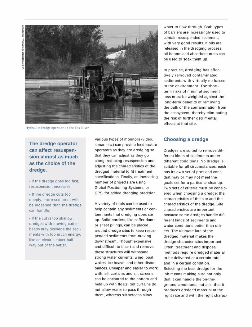
water to flow through. Both typesof barriers are increasingly used tocontain resuspended sediment,with very good results. If oils arereleased in the dredging process,oil booms and absorbent mats canbe used to soak them up.
In practice, dredging has effec-tively removed contaminatedsediments with virtually no lossesto the environment. The short-term risks of minimal sedimentloss must be weighed against thelong-term benefits of removingthe bulk of the contamination fromthe ecosystem, thereby eliminatingthe risk of further detrimentaleffects at that site.
Choosing a dredge
Dredges are suited to remove dif-ferent kinds of sediments underdifferent conditions. No dredge issuitable for all circumstances; eachhas its own set of pros and consthat may or may not meet thegoals set for a particular cleanup.Two sets of criteria must be consid-ered when choosing a dredge: thecharacteristics of the site and thecharacteristics of the dredge. Sitecharacteristics are importantbecause some dredges handle dif-ferent kinds of sediments andwater conditions better than oth-ers. The ultimate fate of thedredged material makes thedredge characteristics important.Often, treatment and disposalmethods require dredged materialto be delivered at a certain rateand in a certain condition.Selecting the best dredge for thejob means making sure not onlythat it can handle the on-the-ground conditions, but also that itproduces dredged material at theright rate and with the right charac-
Various types of monitors (video,sonar, etc.) can provide feedback tooperators as they are dredging sothat they can adjust as they goalong, reducing resuspension andadjusting the characteristics of thedredged material to fit treatmentspecifications. Finally, an increasingnumber of projects are usingGlobal Positioning Systems, orGPS, for added dredging precision.
A variety of tools can be used tohelp contain any sediments or con-taminants that dredging does stirup. Solid barriers, like coffer damsor sheet pilings, can be placedaround dredge sites to keep resus-pended sediments from movingdownstream. Though expensiveand difficult to insert and remove,these structures will withstandstrong water currents, wind, boatwakes, ice heave, and other distur-bances. Cheaper and easier to workwith, silt curtains and silt screenscan be anchored to the bottom andheld up with floats. Silt curtains donot allow water to pass throughthem, whereas silt screens allow
The dredge operator
can affect resuspen-
sion almost as much
as the choice of the
dredge.
• If the dredge goes too fast,resuspension increases.
• If the dredge cuts toodeeply, more sediment willbe loosened than the dredgecan handle.
• If the cut is too shallow,dredges with moving cutter-heads may dislodge the sedi-ments with too much energy,like an electric mixer half-way out of the batter.
WI D
EPA
RT
ME
NT
OF
NA
TU
RA
L R
ES
OU
RC
ES
Hydraulic dredge operator on the Fox River

“Don’t let the differences in
dredge cost be the major factor
in dredge choice. The physical
constraints of the site, the type of
dredging, and the ultimate fate of
the dredged material are the critical
factors that will determine the
best dredge for the job.”
– Jan Miller
Environmental Engineer
US Army Corps of Engineers
teristics for further treatmentand/or disposal. Dredge-specificcharacteristics like availability andcost also factor in.
Site Characteristics
Type of sediment – Some dredgeshandle coarse, loose sedimentswhile others deal more effectivelywith packed sediments. Also, somedredges are able to chew throughminor debris, others cannot.
Depth of water and sediments to bedredged – Each dredge is able todredge to a certain depth. Someperform better in shallow waterthan others.
Amount of sediment to be dredged– Some dredges are good for smalljobs, others for large ones.
Water current – The anchoringmechanism varies with the dredge.Some anchors can handle currents,while others require still water.
Site access – Some dredges aremore maneuverable than others.Maneuverability counts when work-ing in close quarters or where
obstacles need to be avoided. Inparticularly small or hard to reachareas, hand held dredges and/ordivers may be used.
Dredge Characteristics
Amount of water that comes upwith the dredged material –Treatment technologies can handledifferent amounts of water in thedredged material. When excesswater is pulled up with the sedi-ments, it adds to the cost of theproject in two ways. First, it addsextra weight and volume thatneeds to be transported. Second,treatment and disposal options willlikely require sediment dewatering(see p. 37). The extra costs can beworth it, however. Hydraulic dredgestend to bring up the most waterwith sediments, but they offer oneof the cleanest ways to dredge. Inthe dredge table on page 28, thischaracteristic is described as thepercent solids by weight. Thegreater the percent solids, the lesswater the dredge brings up.
Range of production rates –Transportation methods andtreatment technologies can onlyhandle so much dredged materialat a time. If the dredge is producingdredged material too slowly ortoo quickly, a storage site maybe needed to either accumulateenough to transport or hold sedi-ments that must wait to be treated.In the dredge table on page 28, thischaracteristic is described by cubicyards of sediment dredged perhour.
Dredge accuracy – The dredgeneeds to be very accurate for tworeasons. First, it needs to ensurethat all the contaminated sedimentsare removed. Second, it needs tominimize the amount of clean sedi-ment brought up with the contami-
nated sediments. Clean sedimentsthat are needlessly dredged must betransported, treated and disposedafter mixing with contaminated sedi-ments, adding to the project’s cost.
Resuspension – The dredgedescriptions below note the resus-pension issues particular to eachdredge. Resuspension rates vary bythe dredge, site characteristics, andthe experience of the dredge opera-tor. For further discussion of resus-pension see p. 17.
Cost – Costs vary widely with eachproject. Site and sediment condi-tions, treatment technique and proj-ect goals all help determine costs.Generally, dredging costs rangefrom $15 to $50 per cubic yard.Bigger jobs are cheaper because ofeconomies of scale. In other words,the fixed costs (mobilizing thedredge, setting up the dredge site,etc.) can be spread out for largerjobs, working out to fewer dollarsspent per cubic yard of sedimentdredged. Most Great Lakes cleanupsare small, less than 500,000 cubicyards, and tend to be at the higherend of the price range per cubicyard dredged.16 The cost differencesbetween dredges are small enoughthat cost should be one of the lastconsiderations when picking adredge. The physical constraints ofthe site and the dredge along withthe requirements for the ultimatetreatment and disposal of the sedi-ment are of primary importance.
16 Miller, Jan. 2001.
The next section describes manykinds of dredges. At the end of thesection, a table provides specificdata on each dredge, along withsome pros and cons for eachdredge.
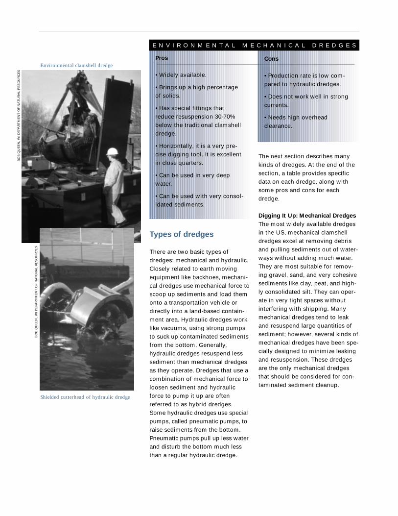
Digging It Up: Mechanical Dredges
The most widely available dredgesin the US, mechanical clamshelldredges excel at removing debrisand pulling sediments out of water-ways without adding much water.They are most suitable for remov-ing gravel, sand, and very cohesivesediments like clay, peat, and high-ly consolidated silt. They can oper-ate in very tight spaces withoutinterfering with shipping. Manymechanical dredges tend to leakand resuspend large quantities ofsediment; however, several kinds ofmechanical dredges have been spe-cially designed to minimize leakingand resuspension. These dredgesare the only mechanical dredgesthat should be considered for con-taminated sediment cleanup.
Types of dredges
There are two basic types ofdredges: mechanical and hydraulic.Closely related to earth movingequipment like backhoes, mechani-cal dredges use mechanical force toscoop up sediments and load themonto a transportation vehicle ordirectly into a land-based contain-ment area. Hydraulic dredges worklike vacuums, using strong pumpsto suck up contaminated sedimentsfrom the bottom. Generally,hydraulic dredges resuspend lesssediment than mechanical dredgesas they operate. Dredges that use acombination of mechanical force toloosen sediment and hydraulicforce to pump it up are oftenreferred to as hybrid dredges.Some hydraulic dredges use specialpumps, called pneumatic pumps, toraise sediments from the bottom.Pneumatic pumps pull up less waterand disturb the bottom much lessthan a regular hydraulic dredge.
Pros
• Widely available.
• Brings up a high percentageof solids.
• Has special fittings thatreduce resuspension 30-70%below the traditional clamshelldredge.
• Horizontally, it is a very pre-cise digging tool. It is excellentin close quarters.
• Can be used in very deepwater.
• Can be used with very consol-idated sediments.
Cons
• Production rate is low com-pared to hydraulic dredges.
• Does not work well in strongcurrents.
• Needs high overheadclearance.
E N V I R O N M E N T A L M E C H A N I C A L D R E D G E S
Environmental clamshell dredge
Shielded cutterhead of hydraulic dredge
BO
B Q
UE
EN
, WI D
EPA
RT
ME
NT
OF
NA
TU
RA
L R
ES
OU
RC
ES
BO
B Q
UE
EN
, WI D
EPA
RT
ME
NT
OF
NA
TU
RA
L R
ES
OU
RC
ES

Enclosed Bucket Dredge and Cable Arm DredgeThese are clamshell dredges thatwere specially designed to mini-mize resuspension. The clamshelldredge gets its name from how itlooks. Clamshell dredges have abucket made of two halves; togeth-er they resemble a clamshell. Thebucket is attached by a cable to acrane that is mounted on a flat-bot-tomed barge or on land. The bargecan be moved short distances byanchors, but must be towed forlonger trips. To dredge, the opera-tor drops the open clamshell intothe sediment. As it is pulled up, thehalves close together, trapping thesediments inside. It dredges sedi-ments by the bucketful and dumpsthem into a barge or scow.Clamshell dredges are classified byhow much sediment they can holdin their buckets – anywhere from 1to 50 cubic yards. Typicalclamshells hold between 2 and 10cubic yards per bucket.
The enclosed bucket and CableArm dredges seal shut with gasketsand tongue-in-groove joints to fullycontain contaminated sediment.The Cable Arm has the addedadvantage of being better able tocontrol how far it dredges into thesediment. It can also remove sedi-ments in layers, leaving a flat sur-face after dredging. It can dredgemore precisely than the clamshell,bringing fewer clean sediments upwith the polluted ones. Enclosedbucket and Cable Arm dredgesresuspend 30 to 70% less sedimentthan clamshell dredges.
Figure 1: Enclosed Bucket Dredge
Figure 2: Cable Arm Dredge
US
EPA
199
4bU
S E
PA 1
994b

head that loosens the sediments sothat the suction pump can pumpthem to the transport, treatment, or
disposal site. For somejobs, the cutterhead canbe removed and thesuction pump can besimply used like a vacu-um. Hybrid dredges arehydraulic dredges thatuse mechanical meansrather than a simplecutterhead to loosensediments. The dredgehead support holds thedredge in the water.The dredge head sup-port can be a simplecable, a special ladderwith the dredge
attached at the bottom, or a sophis-ticated hydraulic arm.
Hydraulic systems suck in a slurry,a combination of sediments andwater. Pneumatic systems pull insediments with very little water inthem. Unlike mechanical dredges,hydraulic and pneumatic dredgesare closed systems: once the sedi-ments enter them, they have nocontact with their environs untilthey reach the transport, treatment,or disposal site. Since both typessuck sediments in rather than justdig them up, they resuspend muchless than mechanical dredges. Theslight resuspension that does takeplace with hydraulic and pneumaticdredges occurs as the cutterheaddislodges sediments or the dredgehead is moved.
Hydraulic dredges can be anchoredand moved in several ways. Manyuse spuds, special poles thatextend down from both sides of thedredge, to anchor to the bottom.The dredge can move by “walk-ing,” using the spuds as legs. Onespud is lifted and the dredge’s
Sucking It Up: Hydraulic
and Pneumatic Dredges
There are four main components tohydraulic and pneumatic dredges:the dredge head, the dredge headsupport, the suction pump, and thepipeline to transport dredged sedi-ments. Hydraulic dredges tend tobe identified by their dredge heads,while pneumatic dredges tend tobe identified by the type of pumpthey use. The dredge head is thepart of the dredge that is insertedinto the sediments. Often, thedredge head is fitted with a cutter-
Pros
• Much less resuspension thanmechanical dredges.
• Some are widely available.
• Often very precise dredgers,bringing up minimal clean sedi-ment.
• Faster than mechanicaldredges.
• Closed system reduces envi-ronmental exposure.
Cons
• Tend to clog, increasing resu-pension and interrupting job.
• Do not handle consolidatedsediment well.
• Pipelines carrying sedimentslurry may be navigationalobstructions.
H Y D R A U L I C D R E D G E S
Figure 3: Cutterhead Dredge
US
AR
MY
CO
RP
S O
F E
NG
INE
ER
S

momentum pivots it on theanchored spud. The first spud isthen re-anchored and the dredge“steps” forward. The dredge itselfmoves forward with the water cur-rents, by pulling itself along a guidewire, or by its own propulsion.Dredges can also use guide wireswithout spuds to move. For exam-ple, two anchor wires can be runparallel to the edge of the dredgesite. A third wire runs perpendicu-lar to and between the two anchorwires. The dredge cleans along thethird wire. After sediments alongthe length of the third wire aredredged, the ends of the third wireare moved down the anchor wiresso that the next row can bedredged.
Cutterhead DredgeThe cutterhead dredge is the mostcommon hydraulic dredge. It uses arotating cutterhead to loosen sedi-ments. A hydraulic pump trans-ports them to the treatment or dis-posal site via a pipeline that can beup to 15 miles long. Usually, thedredge is towed into position andanchored with two spuds mountedon the stern or anchored to sites onland. Two cables controlled bywinches swing the dredge back andforth. Sediment shields, gas collec-tion systems, underwater cameras,and sensors have all been usedwith this type of dredge to maxi-mize accuracy and minimize resus-pension.
Portable Hydraulic DredgeA smaller version of the plain suc-tion dredge, the portable hydraulicdredge is easily moved and effec-tive in shallow water. Portablehydraulic dredges usually havepipes that are less than 24 inchesin diameter.
Plain Suction Head DredgeThe plain suction head dredge isessentially a cutterhead dredgewithout the cutterhead. It works likea vacuum, simply sucking up sedi-ments with a pipe. Water jets canbe added at the suction mouth tohelp dislodge sediments, but theymay increase resuspension. It canbe maneuvered by cables andwinches or by divers.
Figure 3:
Plain Suction Head Dredge
US EPA 1994b
Pros
• Brings up sediments withvery little water, up to 80%of the sediments’ originaldensity.
• Very low resuspension.
• Provides continuous,uniform flow of dredgedsediment.
• Effective at low power.
• Closed system reducesenvironmental exposure.
Cons
• Can clog, increasingresuspension and inter-rupting job.
• When moved arounddredge site can suck uplots of excess water.
P N E U M A T I C D R E D G E S

Horizontal Auger DredgeThis commonly used dredge has atype of screw, or auger, to break upsediment and carry it to the dredgepump. A retractable mud shieldover the auger can control resus-pension, but increases the probabil-ity that the dredge will clog. Fouranchored cable wires hold thedredge in place and move it like apendulum from side to side. Thehorizontal auger dredge canremove layers of sediment between4 and 20 inches thick. Two commonbrands of horizontal auger dredgeinclude the Mudcat and the LittleMonster.
Figure 5: Horizontal Auger Dredge
US
AR
MY
CO
RP
S O
F E
NG
INE
ER
S
Pros
• Can work with a widervariety of sediments thanhydraulic dredges.
• Low resuspension com-pared to mechanicaldredges.
• Faster than mechanicaldredges.
• Closed system reducesenvironmental exposure.
Cons
• Can clog, increasingresuspension and inter-rupting job.
• Some cutter headsincrease resuspension overhydraulic dredges.
• Pipelines carrying sedi-ment slurry may be naviga-tional obstructions.
H Y B R I D D R E D G E S

Screw Impeller DredgeThis dredge is a large screw withan agitator at the bottom. Thescrew sinks into the sediment andthe agitator loosens the sediment.The screw then brings the sedi-ments to a centrifugal pump thatpressurizes the slurry and deliversit via a pipeline.
Specialty Dredges
The following dredges are innova-tive pneumatic and hydraulicdredges. Though not widely usedin the United States, they werespecifically designed to dredge con-taminated sediments.
Eddy PumpThe Eddy Pump uses a swirlinghydraulic eddy current to suck upcontaminated sediments. A rotor isinserted into the sediments andspins, forcing sediments into anuptake chamber. When the pumpoperates, the surface of the sedi-ment collapses downward to theimbedded nozzle like a milkshakebeing sucked up through a straw.There is little or no sediment resus-pension because there is no cutter-head and the intake nozzle is com-pletely imbedded in the sediment.
Figure 7: Eddy Pump Dredge The Eddy Pump consists of an energy generating rotor (1)
attached to the end of a drive shaft (2) and placed within a volute (3). As the rotor begins
to spin, it sets into motion the fluid present within the volute and the adjoining intake
chamber (4). At normal operating speeds, this spinning fluid is forced down into the hol-
low center of the intake chamber, where it creates a high speed, swirling synchronized col-
umn of fluid (5) which agitates the material (6) to be pumped (eg. sludge, sand, clay, or
silt). This swirling column of fluid creates a peripheral “eddy” effect (7) which causes the
agitated material to travel by reverse flow up along the sites of the intake chamber into the
volute. Here the material, under pressure from below, is forced into the discharge pipe (8).
(Courtesy of Xetex Corporation)
Figure 6: Screw Impeller Dredge
US EPA 1994b
1 Agitator
2 Screw
3 Pressuring device
4 Compressed air
5 Compressed air nozzle
6 Plug flow
7 Delivery lineS
CE
NIC
HU
DS
ON
, AD
VAN
CE
S IN
DR
ED
GIN
G

Airlift DredgeThe Airlift dredge can be operatedfrom land or supported by a craneor barge. It uses a rotating cutter-head to loosen sediments. It thenreleases compressed air into a riserpipe that is open on both ends. Asthe compressed air expands, it cre-ates a current that carries waterand sediment up into the pipe.
Amphibex DredgeThe Amphibex dredge is a combi-nation hydraulic and mechanicaldredge. Like a backhoe, theAmphibex dredge has a bucketwhich can be used to removedebris such as large rocks, garbage,and tree limbs. Screw-shaped(auger) cutterheads loosen sedi-ments and feed them to a hydraulicintake. The self-propelled dredge isheld in place by spuds and side sta-bilizing arms, providing great flexi-bility in positioning and maneuver-ability. The dredge can crawl alongland or through shallow water,slide down banks, and float.
Waterless DredgeThe Waterless dredge is able toremove sediment at relatively highdensity because it uses a sub-merged pump and a half-cylindricalshroud to cut water inflow. Theshroud also contains resuspendedsediment. It can remove sedimentsat 30 to 50 percent solids byweight.
Wide Sweeper Cutterless DredgeThe Wide Sweeper cutterlessdredge is designed to remove con-taminated sediments without resus-pension. It features a hydraulicallyarticulated shroud, acoustic sensorsto gauge sediment characteristics,two pumps (one submerged) andan underwater television camera toassist the operator.
Pneuma PumpBy changing the air pressure in itsthree cylinders, the Pneuma Pumpcreates pneumatic force that sucksup sediments through its dredgepipe – much like the Oozer Pump.The Pneuma Pump acts like a pis-ton pump: as each cylinder fillswith sediment, the compressed airacts as a piston and forces sedi-ments through a valve to the dis-charge pipe line. It also has a vacu-um system to help in shallowwater. The Pneuma Pump caneither be suspended from a craneor barge or mounted on a ladderlike a conventional cutterheaddredge. The best dredging resultsoccur when Pneuma Pumps aremounted on a ladder.
Oozer PumpBy changing the air pressure in itstwo cylinders, the Oozer Pump cre-ates pneumatic force that sucks upsediments through its dredge pipe– much like the Pneuma Pump dis-cussed next. The whole process ismade more efficient with a centrifu-gal vacuum. The Oozer Pump ismounted on a ladder and operatedlike a conventional cutterhead. Fiveacoustic sensors measure the den-sity of sediment layers and under-water television cameras aid theoperator. Other accessories areavailable, including cutterheads forloosening sediment and gas scrub-bers for collecting toxic gases.
Figure 8: Oozer Pump
Figure 9: Pneuma Pump
SC
EN
IC H
UD
SO
N, A
DVA
NC
ES
IN D
RE
DG
ING
SC
EN
IC H
UD
SO
N, A
DVA
NC
ES
IN D
RE
DG
ING

SC
EN
IC H
UD
SO
N, A
DVA
NC
ES
IN D
RE
DG
ING
Clean-up DredgeThe hybrid Clean-up dredge uses ashielded auger (screw) to dislodgesediment as it swings back andforth. The rotating auger pushesthe sediments with its threads to ahydraulic pump. A cover and mov-able wing contain resuspendedsediment and gas bubbles whileminimizing the amount of watertaken in by the dredge. Grates posi-tioned next to the auger keepdebris from clogging the dredge.The dredge is equipped with sonarto monitor dredging depth and aTV camera to monitor resuspen-sion. The Clean-up dredge workswell with soft mud or sand.
Figure 10:
Cleanup Dredge
Figure 11: Matchbox Dredge
Matchbox DredgeThe Matchbox dredge useshydraulic pistons to loosen sedi-ments. The sediments are thensucked through a grate to screenout debris and then into a funnelintake. A cover with valved open-ings on each end, resembling amatchbox, encloses the grate andthe funnel intake. As the dredge isswung from side to side, the valvein the direction of the swing opensso that sediment may enter. Thecover is designed to reduce waterinflow and collect gas bubblesescaping from the sediment.
Refresher SystemAnother type of cutterhead dredge,the Refresher uses a helical auger,or screw, to loosen the sediments.It is also equipped with positioningequipment and valves to preventback flow if there is an emergencyshut down. A cover and shuttersminimize resuspension and wateruptake. The cover is flexible andcan be adjusted to the bottom con-tour with hydraulic controls.
Figure 12: Refresher System
US
EPA
1994b
US
EPA
1994
b

Production Rate
30-600 yd3/hr 1,2
30-600 yd3/hr 1,2
33-3,270 yd3/hr 1,2
1,000-10,000 yd3/hr 1
5-50 yd3/hr 1
50-160 yd3/hr 1,2
310 yd3/hr 1
330-800 yd3/hr 1
60-2,600 yd3/hr 1
60 yd3/hr 1
90 yd3/hr for sand100 yd3/hr for sludge 4
500-1,960 yd3/hr 1,2
24-80 yd3/hr 1,2
65-1300 yd3/hr 1,2
% Solids by Weight
Near original density 1,2
Near original density 1,2
10-20 1,2
10-15 1,2
10-40 1
10-40 1
70 ▼Lower if dredge head ispicked up and moved a lot orif dredge is clogged 1,3
25-80 ▼Lower if dredge headis picked up and moved a lotor if dredge is clogged 1,2,3
25-80 ▼Lower if dredge headis picked up and moved a lotor if dredge is clogged 1,2,3
25-40 1,2
45 4
30-40 1,2
5-15 1,2
30-40 1,2
Dredge Name
Enclosed Bucket
Cable Arm
Cutterhead
Plain Suction Head
Portable Hydraulic
Horizontal Auger
Eddy Pump
Oozer
Pneuma
Airlift
Amphibex
Clean-Up
Matchbox
Refresher
Sediment Type
Gravel, sand,consolidated silt, clay
Gravel, sand,consolidated silt, clay
All types including clay,silt, sand, hardpan,gravel and rock
Soft, free- flowing mate-rial or granular materiallike sand
Soft, free- flowing material
Loose, free flowingmaterial
Loosely consolidatedsilt or clay
Loosely consolidatedsilt or clay
Sand, silt, clay
All types, has rake to remove debris 4
Soft mud, sand; silty clay
Consolidated silt, loosely packed sand
All types
Resuspension
Enclosed bucket and Cable Armdredges resuspend 30 to 70 % lesssediment than clamshell dredges
Enclosed bucket and Cable Armdredges resuspend 30 to 70 % lesssediment than clamshell dredges
Strongly influenced by the specificdredge design and operation
Virtually none without water jets
Virtually none
Virtually none
Virtually none
Only if dredge is moving too fast
None
Very low
Information notavailable
Only with starting and stopping pump and changes in swing direction
Very low
Increases with speed of dredge
Dredge Accuracy
Information notavailable
Horizontal: 0.4 in 5
Vertical: 12 in Horizontal: 0.4 in 2
Vertical: 12 in Horizontal: 0.4 in 2
Maneuvered by hand
Vertical: 6 in Horizontal: 0.5 in 2
Vertical: 12 in Horizontal: 0.4 in 2
Vertical: 12 in Horizontal: 0.4 in 2
Vertical: 12 in Horizontal: 0.1 in 2
Information notavailable
Vertical: 12 in Horizontal: 0.4 in 2
Vertical: 12 in Horizontal: 0.4 in 2
Vertical: 12 in Horizontal: 0.4 in 2
1 Cleland, 2000 2 USEPA, 1994b. 3 Miller, 2001. 4 Normrock Industries, Inc., 1995-2000. 5 Environmental Dredging Guide, Cable Arm Inc.
** The above information was not available for the screw impeller, wide sweeper cutterless, and waterless dredges.
SPEC
IALT
Y
H
YDRA
ULI
C
MEC
HA
NIC
AL

Cons
• Does not work well in strong currents • Needs high overhead clearance
• Does not work well in strong currents • Needs high overhead clearance
• Tends to leave raised rows of sediments on the sediment surface • This can be min-imized with innovative dredging techniques
• Ineffective for consolidated sediments • Optional water jets increase resuspension
• Does not perform well in water • Production rates tend to be low
• Not effective in shallow water• Difficult to maneuver in high winds
• Not effective for consolidated sediments
• Debris causes the pump to clog, increasing resuspension
• Debris causes the pump to clog, increasing resuspension
• Does not work in water shallower than 20 feet • Relatively expensive
• Will not work for highly compacted sedi-ments
• Debris tends to clog the dredge
• In two different projects, resuspensionincreased four to five times as the dredgingspeed doubled
Pros
• Widely available • Brings up solids without much water • Horizontally, it is very precise, it excels inclose quarters • Can be used in very deep water • Can be used with very consolidated sediments • Does not leak as much as clamshell
• Widely available • Brings up solids without much water • Horizontally, it is very precise, it excels inclose quarters • Can be used in very deep water • Can be used with very consolidated sediments• Does not leak as much as clamshell • Does not leave a cratered sediment surface
• Most common hydraulic dredge in the U.S. • Very versatile and efficient • Can operate continuously,reducing costs
• Well suited to removing unconsolidated material • Virtually no resuspension without water jets • Highly maneuverable
• Convenient for isolated, hard to reach areas • Economical for small jobs can be operated in water asshallow as 2 feet • Since it is maneuvered by hand, can go around rocks and large debris
• Leaves sediment surface flat • Infrared light, echo and depth sounders all monitor dredge position • Able to handle muck and chew through woody debris
• Low weight • Does not need much energy • Does not pull out much water with sediments, can pumpsediments with as little as 5% water • Can handle debris very well
• Sediments can be removed at 30-80% of the density in the waterway • One study found suspended solids atbackground concentrations within three meters of dredge • More efficient at low power than conventional centrifu-gal pumps • Equipment does not agitate sediments, has very limited contact with them–minimizing resuspension.
• Sediments can be removed at up to 80% of the density that they are found in the waterway • Continuousand uniform flow • More efficient at low power than conventional centrifugal pumps • Equipment doesnot agitate sediments and has very limited contact with them – minimizing resuspension.
• Relatively high solids concentration • Can be put together relatively easily • Can handle a wide range ofsediment types • Very efficient in deep water
• Very good in hard to reach sites, shallow water, strong currents, and rough coastlines • Relatively highsolids concentration
• Virtually no resuspension • Special tools to monitor dredge accuracy and resuspension • Produces uniform slurry
• Very low resuspension • Has a computer to maintain optimal dredging efficiency
• Can operate in shallow or deep water • Less resuspension than a conventional cutterhead dredge
Dredging Depth
0-157 ft 1,2
0-157 ft 1,2
3-60 ft 1,2
5-160 ft 1
2-50 ft 1
2-16 ft 1,2
3-100 ft 1
0-160 ft 1,2
0-500 ft 1
20ft and deeper 1
19.5 in to 21 ft 4
3-80 ft 1,2
3-85 ft 1,2
3-115 ft 1,2

they were constructed as an inex-pensive means of containing navi-gational dredge spoils. Generally,CDFs were not designed to holdhighly contaminated dredgedmaterial. Between 1960 and 1994,50 CDFs were constructed aroundthe Great Lakes.17
CDFs are prone to leaking. Figure13 illustrates a typical CDF and theways in which contaminants canescape. The dredged sediment sitsat the bottom in the saturatedlayer. Confined disposal facilitiesare designed to hold saturatedmaterial that is 10 to 50 percentsolids by weight. The unsaturatedlayer consists of capping materialand soil. CDFs are usually coveredwith vegetation. Dikes at the sidesof the CDF contain the contami-nants and capping materials. Theweir is a special pipe that channelssurface runoff to a wastewatertreatment plant. Contaminants canescape the confines of the disposalfacility by leaching through thebottom into groundwater, volatiliz-ing (evaporating) off the top intothe air, being taken up by the vege-tation at the top, or seepingthrough the sides. Each of thesepathways must be limited as muchas possible. CDFs require extensivemonitoring programs to ensurethat contaminants are not escapingat unacceptable levels.
Containment risks are similar tothose posed by capping. There is arisk that contaminants can leakthrough the containment into thesurrounding ecosystem. CDFs willalways be subject to forces workingto break them down, like ice scour,
Confined Disposal
Facilities (CDFs)
This disposal method uses coffer-dams, dikes or other structures toisolate contaminants in a portion ofthe waterway. In Waukegan Harborin southern Lake Michigan, forexample, a boat slip was walledoff, contaminated sediments wereplaced inside the walls, and thewhole thing was then capped like ahazardous waste land fill. Note,though, that hazardous waste land-fills have bottom liners to preventleaking, and this CDF did not.Confined disposal is the mostwidely used disposal technology inthe Great Lakes, mainly because
There are four major optionsfor contaminated sedimentsonce they are dredged:
Confined Disposal Facilities (CDFs),upland landfills, beneficial reuse andtreatment. Treatment can be usedalong with any of the three otheroptions. In some cases, treatment isnecessary to prepare the sedimentfor reuse or disposal. In other cases,treatment reduces the amount ofsediments that need to be disposedor destroys contaminants altogether.Though more expensive at the out-set, treatment technologies oftenprovide a way to permanentlyremove contaminants, eliminatingany future risks of exposure.
disposal options
Confined disposal facility in Saginaw, MI
EPA
,GR
EA
T LA
KE
S N
AT
ION
AL P
RO
GR
AM
OFFIC
E
17 USEPA, 1994a.

which chemical or biological treat-ment might be applied. If success-ful in destroying the contaminants,the cost of long-term monitoringwould be eliminated.
waves, storms, etc. Also, the struc-ture itself alters water flows andcould create more erosive forces.
Areas suitable for a CDF must havelow water flow and no boat traffic.Backwater areas, slips, turningbasins, and some wide areas ofrivers are examples of acceptablelocations, though the effects of thephysical containment structure onflow patterns, flooding, navigation,and habitat need to be assessed.Ideally, the containment areashould not be subject to erosiveforces, though this can never beguaranteed.
Construction of the isolation cham-ber confers most of the cost of con-tainment. Monitoring plays a keyrole, before, during, and after theconstruction process. In cases likeWaukegan Harbor, other ongoingcosts include the continuous opera-tion of drawdown wells to ensurethat water is always being pulledinto the containment structurerather than being released. Wastewater treatment systems add to thecosts. Containment also provides amore controlled environment in
Figure 13: Potential Contaminant Loss Pathways from a CDF
US
EPA
1994
b
Pros
• Disposal in CDFs is cheaperthan in upland landfills.
• CDFs can be located closerto the dredge site, reducing theneed to handle and transportcontaminated sediments.
• CDFs can provide a con-trolled area for the use ofsome advanced treatmenttechnologies.
Cons
• Contaminants may leak outof the CDF.
• Control of some contami-nant-loss pathways may beexpensive.
• CDFs require long-termmonitoring and waste watertreatment.
• Other uses of CDF sites thatcontain contaminated materialsmust be carefully considered.
• CDFs provide limited disposalspace.
• It can often be very difficultto site new CDFs.
C O N F I N E D D I S P O S A L F A C I L I T I E S

Pros
• Landfilling may be the mostcost effective option for smallvolumes of contaminated sedi-ments.
• In cases where contaminantsare tightly bound to sedimentsor are immobilized or encapsu-lated via a technology, landfill-ing offers a relatively safemeans of sequestering contam-inants from the environment.
Cons
• There is a risk that the landfillmay be compromised and toxicmaterial will leak into ground-water or surrounding lands.
• Space in landfills is very limit-ed and it is becoming increas-ingly difficult to site new ones.
• Landfills require long-termmonitoring and waste watertreatment.
• Contaminated sedimentsmust usually be transportedlonger distances for uplandlandfilling, increasing costsand the risk of accidents.
U P L A N D L A N D F I L L SUpland Landfills
Very simply, landfills are holes inthe ground augmented with severalkinds of barrier systems. Linerscover the bottoms and sides oflandfills while water drainage andcollection systems also help pre-vent leaking. Since landfills are notequipped to deal with much excesswater, dredged material needs tobe dewatered before landfill dispos-al. Finally, caps or covers keep con-taminants from seeping out thetop. Toxic and hazardous wastelandfills are required to have bettersafeguards because they housedangerous materials. Modern-daylandfills are fairly effective at con-taining contaminants.
There are three kinds of uplandlandfills: standard solid-waste land-fills, toxic waste landfills, and haz-ardous waste landfills. Toxic andhazardous waste landfills are sub-ject to more stringent regulations.Highly contaminated sedimentsmust go in toxic or hazardouswaste landfills while less contami-nated materials can go in standardsolid-waste landfills.
Landfills are cordoned off into cells.Generally, only a few cells areloaded at a time. It is possible toput contaminated sediments in anaccessible cell and go back at alater date to treat the sediments.
Landfills charge a fee when theyaccept material. Monitoring andwastewater treatment costs areincluded in the fee. Toxic and haz-ardous waste landfills can be threeto six times more expensive thanstandard solid-waste landfills, mak-ing it more expensive to dispose ofhighly contaminated material.Because landfills charge by vol-ume, it is often cost-effective to use
one or more separation technologies(described in the next sections) toreduce the volume of sediment thatneeds to be disposed.
Beneficial Reuse
Historically, dredged sedimentshave been used for a number ofprojects including beach nourish-ment; replacing eroded soils;amending marginal soils for agri-culture, horticulture and forestry;building wildlife habitat or wet-lands; construction fill; and dailycaps for landfills. All of these proj-ects have been referred to as bene-ficial reuse. The use of contaminat-ed sediments for these projects,however, can call the term “benefi-cial” into question. Using contami-nated sediments in any projectwhere they will be exposed to theecosystem or food web defeats thepurpose of dredging them in thefirst place. Currently, there are nofederal guidelines on the beneficialreuse of contaminated sediments.Sometimes, inappropriate “benefi-cial reuse” projects have provided aconvenient, cheap way to disposeof contaminated sediments.
Beneficial reuse projects do holdpromise – as long as contaminationlevels are very low and the usedoes not directly expose theecosystem to contaminants. Forexample, sediments with very lowcontaminant levels may be consid-ered for landfill cover or as con-struction fill. The treatment tech-nologies described below increasethe options for beneficial reuse.Often, cleaner portions of sedimentcan be separated out. Some treat-ment technologies extract contami-nants while others permanentlylock them into a hardened material.After testing to ensure low contam-inant levels, any of these sedimentproducts can be considered forbeneficial reuse projects. Severalagencies are currently exploringmarkets for products made fromtreated sediments from the NewYork/New Jersey harbor. The abilityto produce a safe, marketable prod-uct from treated contaminated sedi-ments could defray the costs ofdredging and treatment.

Number of different types of par-ticles present in the sediment –most sediments consist of manydifferent kinds of materials.Contaminants preferentially bind tosome types of materials. For exam-ple, organic material in sedimentsoften contains the highest concen-tration of pollutants.
How easy it is for oxygen to enterand chemically alter the sediments(oxidation-reduction potential) –dredged material initially does nothave much oxygen bound to it.After excavation, oxygen begins toseep in and bind to sediments in aprocess called oxidation. Higheroxygen levels can cause contami-nants (mainly metals) to leach outof the sediments. This could begood or bad depending on thegoals of the project. For example,oxidation is a very necessary part ofbioremediation.
pH and changes in pH (acid oralkaline conditions) – metals bindmore tightly to sediments dependingon their acidity or alkalinity. Mostmetals tend to bind tightly in alka-line conditions and leach in acidicconditions.
Particle size distribution – Fine par-ticles like clays and silts are moredifficult to handle while sand is typ-ically easier to handle. Smaller par-ticles can hold more contaminantsthan larger particles because theyhave more surface area per vol-ume. More surface area meansmore places to which contaminantscan bind. Smaller particles alsotend to pack more tightly, leaving
Contaminants usually attach tosolid particles in sediment.Sometimes, contaminants are morelikely to attach to particles madeout of a specific material or to parti-cles of a specific size. Often organicmaterial and fine particles, thoseless than about 40 microns(micrometers) in diameter (smallerthan a grain of salt), hold themajority of the contaminants. Thephysical and chemical properties ofdifferent types of sediments makesediment treatment very projectspecific. Properties affecting thesuccess or failure of treatment tech-nologies include:
Type and strength of bondsbetween contaminants and sedi-ment particles – fine particles usu-ally have a higher surface electricalcharge than larger particles. Thecharge binds contaminants verytightly to small particles.
Treatment techniques attemptto change contaminateddredged material so that it
meets the criteria and goals set bythe community, the planning team,the site owner, and/or regulatoryagencies. Treatment technologiescan remove contaminants fromdredged material, destroy contami-nants, or change the contaminantsin some way so that they no longerpose a threat to the environment. Insome cases treatment producesrecyclable or re-useable material.
Treatment techniques are availablefor several different types of con-taminants in sediment. Many tech-niques were tested during govern-ment-sponsored demonstrationprograms.18 A number of technolo-gies have been successfully used atfull scale in recent years. The gen-eral types of treatment technolo-gies are discussed below.
EPA
, GR
EA
T L
AK
ES
NA
TIO
NA
L P
RO
GR
AM
OFF
ICE
18 Netherlands Institute for Water Managementand Waste Water Treatment, 1992; USEPA,1994b; Wardlaw et al 1995.
treatment options

are chosen based on the resultsof these studies.
Characterization Study – A charac-terization study analyzes a compos-ite sample of the dredged materialto determine its chemical andphysical properties. Among otherthings, characterization study deter-mines the size of the particles inthe sediment and the density of thesediment. The characterizationstudy is different than the sitecharacterization process performedbefore dredging (see p. 7).
Broad Treatability Study – Thislaboratory evaluation determineswhether the sediment is treatableand, if so, what treatment methodsare likely to succeed. Broadtreatability studies assess charac-teristics like:• concentrations of contaminants
on differently sized particles,• concentrations of chemicals in
parts of the sediment that are ofdifferent densities,
• settling characteristics, • thermal properties, • how tightly metals are bound to
sediment particles, • sediment density at different
water contents, and• biological properties (including
types of microorganisms present).
Next, two kinds of demonstrationsdetermine whether the treatmenttechnologies will work for particularsediments.
Bench Scale Demonstrations –Once the broad treatability studydetermines which treatment meth-ods are likely to work, selectedtechnology vendors can performbench scale studies. Bench scaletests, often simply called benchtests, help determine which tech-nology is best suited for the project.
Discovering Sediment
Characteristics and
Testing Technologies
All treatment projects require anaccurate assessment of the quanti-ty, composition, and location of thedredged material. Without thisinformation, it is impossible tochoose the most appropriate treat-ment methods. Moreover, prelimi-nary research helps avoid problemssometimes associated with treatingsediments. Each dredge load maycontain pockets of different kinds ofsediments. The amount of dredgedsediment and differences betweenthe sediments in each dredge load(heterogeneity) can be underesti-mated, causing problems at thetreatment site. Preliminary research
can help mitigate these problemsand determine the appropriatetreatment option.
Preliminary research includes twostudies that examine the specificcharacteristics of the dredgedmaterial and the contaminants.Potential treatment technologies
very little space between the parti-cles (pore space). With so littlespace between the particles, thereis little room for contaminants tomove around when subjected totreatments intended to releasethem from the sediment.
Agglomerations – contaminantsand naturally occurring materialscan form complexes, calledagglomerations, which are difficultto handle chemically or physically.
Dangerous properties – dredgedmaterial can have toxic, caustic,or other properties that make thematerial hazardous to workersand the environment and requirespecial handling.
EPA, GREAT LAKES NATIONAL PROGRAM OFFICE
Sediment monitoring and sampling vessel
known as the Mudpuppy.

Each vendor performs in-housetests on a composite sample of thecontaminated sediment. Benchtests use laboratory equipment thatmight not be similar to equipmentused for full-scale treatment. Somevendors will perform bench scaletests at no charge. Bench testsshould be inspected by either theproject manager or a specializedaudit firm.
Pilot-Scale Demonstrations – Theseon-site tests are not always neces-sary but should be considered –especially if the chosen technologyis unproven at the commercialscale. A pilot test usually lasts twoto four weeks. The vendor treatssome material for a specified timeto adjust the treatment process sothat it runs as efficiently as possiblefor the particular sediment found atthe site. Once the adjustments havebeen made, the vendor performs aseries of audited performance runs.The results of the performance runsdetermine whether or not to pro-ceed to full scale.
Just in Case: Safety
Features
The two main safety risks whenhandling contaminated sedimentare air emissions and spills. Thereare a variety of safety features thatcan be used with treatment tech-nologies to reduce the risks posedby air emissions and spills. Sometechnologies come with safety fea-tures built in. Often, these safetyfeatures are called “mitigatingmeasures.”
Some chemicals, known as volatilechemicals, tend to evaporate easi-ly. Typically volatile contaminantswill stay put when sediment isundisturbed, but will evaporate(volatilize) after sediment is
dredged and exposed to air. Sometreatment processes producevolatile emissions even when thecontaminants themselves are notvolatile. For example, as a treat-ment process breaks down organicmolecules, smaller, lighter, morevolatile molecules may form andescape. Off-gas collection systemscontain and treat volatile emis-sions. If the treatment technologydoes not already have an off-gascollection system built in, testingprior to the project will determinewhether one is needed.
Spills pose another risk when han-dling contaminated sediments.There is always a small chance thatequipment will fail or storage con-tainers will be compromised,spilling contaminated sediments.Also, in case any part of theprocess from dredging to treatmentis stalled, storage space for sedi-ments should be provided to pre-vent backup or spills.
Some of the more common safetyfeatures are:
Off-gas collection and treatment –Volatile contaminants (off-gases)are either collected by routing airemissions directly through a filteror “scrubber,” or by using a vacu-um system to collect air and thenroute it through a filter system.Scrubber systems spray a liquid orfine particle mist into the off-gasthat knocks the contaminants out ofthe air. Filter systems may be madeof fabric (an air bag or membrane),activated carbon, absorbent foam,liquid (the gas actually passesthrough a liquid such as an organicsolvent) or natural organic mattersuch as peat moss or compost (abiofilter).
Temporary cover – In the event thatoff-gas collection mechanisms failto contain volatile emissions ortheir reliability becomes suspect,the sediment handling and treat-ment areas should be completelyenclosed in temporary structuresthat resemble greenhouses. Withinthese structures, an air ventilationsystem routes all indoor airthrough a filter system.
Spill containment – Spill contain-ment structures help contain sedi-ment or liquid spills. Earthen bermsare often used to contain spills attemporary outdoor sites. Theseearthen curbs surround the treat-ment site or handling area. In somecases the berm and entire treatmentor handling area is covered with athick plastic liner and re-coveredwith sand or earth. For permanentor indoor sites, containment struc-tures consist of concrete or asphalttreated with a plastic coating to pre-vent contaminants from penetratingthe pores of the material. Spill con-tainment areas should hold at least125% of the maximum expectedvolume of the contaminated sedi-ments. For outdoor sites, the struc-tures must be even larger to containthe rainwater from any storms thatmay coincide with a spill.
Extra storage space – It is alwaysa good idea to have additionalstorage space for untreated sedi-ment, water or treated sediment.While the process flow calculationspredict the normal storage volumesneeded, operations seldom proceed“normally”.

CostUsually more than one pre-treat-ment technology is used for a proj-ect. A typical pre-treatment systemincludes screening, dewatering,and size separation. Depending onhow many technologies are used,pre-treatment technologies costbetween $10 and $50 per ton(approximately $15 and $75 percubic yard) of sediment treated.
� The major pretreatment
technologies include:
• Dewatering
• Separation (by size, density
and magnetic force)
• Water Treatment
• Washing
cleaner (sand) portion but in somecases the removal rate is 50% orless from the other portions.19 Notethat the contaminated portion ofthe sediment will have higher con-centrations of pollutants than theuntreated sediment did. The clean-er portion is removed, leaving thesame amount of pollutants in asmaller volume of fine-grained,contaminated sediments. The con-taminated portion goes for furthertreatment or for proper disposal.Treated water, if clean, is dis-charged to surface water. If not, itis sent through a water treatmentsystem.
Size and Set-up TimePre-treatment structures areportable and relatively easy to setup and take down. For small jobs,the setup might take a week or less.For large jobs, setup could take twoto four weeks. The size of pre-treat-ment structures is completelydependent on the size of the joband the specifications for treat-ment. If settling basins are notneeded (see below), the footprintshould be less than 1/4 acre. With asettling basin, a footprint of severalacres may be needed.
Treatment RatePre-treatment equipment is sized tosuit the project, therefore almostany treatment rate is possible.Often, 50 tons of wet sediment canbe treated per hour – with theexception of passive de-wateringtechniques. Passive de-wateringtechniques can take years.
As the name implies, pre-treatment technologiesphysically or chemically
change the sediment before it goesto the main treatment process orfor disposal. Many pre-treatmenttechnologies reduce the volume ofdredged material that needs furthertreatment or disposal or improvethe physical quality of the dredgedmaterial for further handling andtreatment. Some pretreatment tech-niques try to separate cleaner por-tions of the dredged material fromthe more contaminated parts.Others separate the water in thedredged material from the solids.Most sediments must undergo pre-treatment before being disposed ortreated further. At the very least,sediments almost always must bede-watered.
Pre-treatment technologies can beused for sediment containing anyor all pollutants, though not all pol-lutants can be removed with pre-treatment. Pre-treatment does notdestroy contaminants, it only triesto separate them from the cleansediment or prepare the sedimentfor further handling. Pretreatmenttechnologies yield:
• water;• a smaller, fine-grained, contami-
nated sediment portion;• a coarse-grained, cleaner portion
of sediment; and• large debris such as logs, litter,
rocks, and shellfish.
EffectivenessOften, over 90% of the contami-nants can be removed from the
pre-treatment technologies
19 Wardlaw, 1995.

Separation Techniques
Separation techniques try toseparate the contaminated portionsof the sediment from the cleanerportions. Portions that are cleanenough may be reused or recycled.Separation techniques alwaysproduce a portion of the sedimentthat has to be additionally treatedor disposed. In many cases, separa-tion technologies reduce the overallcost of the project because theyreduce the volume of contaminatedsediment that needs further treat-ment or disposal. Dredged sedimentcan be separated by size, densityand magnetic force. Size and den-sity separation processes separatethe smaller, usually more contami-nated particles from the relativelyclean sand and gravel. Magneticseparation removes metals fromthe sediment.
Size separation
Most dredged material contains asmall amount of debris, such as plantmaterial, metal products, animalshells and bones, rocks, aggregatesof finer particles, and litter. Thismaterial can damage handling andtreatment systems, impede theflow of sediment, and carry a highcontaminant load. A number oftechnologies have been designedspecifically to separate this material.These include coarse screens,trommels (rotating drums withholes in the sides), and skimmers.
Since contaminants tend to bind tofine particles, technologies thatseparate larger particles from fineparticles effectively remove cleanerportions of sediment from morecontaminated portions.Hydrocyclones or screens accom-plish this task quite easily.Hydrocyclones are small conicalchambers with an outlet at the bot-
“Lagooning” – long-term settlingand consolidation of the solids in ashallow disposal cell.
Evaporative techniques – allowingwater to evaporate from the sedi-ments after they have settled andthe surface water (supernatant)has been removed.
Centrifugation – rapidly rotatingwet sediments in a chamber, usingcentrifugal force to drive water outof the solids and through a mem-brane or screen and trapping thesolids in the chamber.
Filtration – passing the waterthrough a filter material such assand, cloth or paper and catchingthe solids on the filter material(this process is used for watercontaining up to about 2% solids).
Filter presses – squeezing water outof solids using high pressure rollersor plates.
Dewatering methods can be coordi-nated with the other treatment anddisposal options.
Dewatering
Dewatering is one of the first stepsin handling dredged material. A lotof water accompanies dredged sed-iments, especially if hydraulicdredges are used. It is often neces-sary to remove some water beforetreatment or transport. Physicalmethods are generally used todewater sediment. Physical dewa-tering methods include:
Clarification – spreading out thesediments in a specially designedtank or pond, or in a ConfinedDisposal Facility, barge, or smallportable tank and allowing the solidparticles to settle, sometimes withthe addition of a chemical settlingaid. The water above the sediment(supernatant) is then removed andsent for further treatment or disposal.
Which Dewatering Methods Are Best?
Volatile contaminants like PCBs can evap-orate along with water in most dryingprocesses, releasing toxic chemicals to theair. Mechanical dewatering methods (cen-trifuges and filter presses), though moreexpensive, dry the sediments faster andthereby minimize evaporative pollution.
Figure 14: Belt Filter PressU
SE
PA 1
994b

the dense material up the inclineuntil it spills out the top into acontainer. Lighter material andwater flow out over the bottom lipof the basin.
Magnetic separation
Magnetic techniques separatemetallic objects or particles fromsediment. The objects removed aregenerally larger than about 1 mm(0.04 inches). There are a variety ofdifferent configurations for magneticseparation. Usually the sediment
faster than lighter ones, forming aheavier, more dense layer of sedi-ment at the bottom. In addition tohydrocyclones (which separate bysize and density), the followingtechnologies separate by density orsettling rate:
Dense media settling basins – alsocalled upflow classifiers; these aretanks in which there is a constantupward flow of water. When thedredged material is fed to the tank,heavier particles sink while thewater carries lighter, more contami-nated particles upward.
Longitudinal passive settlingbasins – these are essentially longnarrow basins. The dredged mate-rial is fairly swiftly fed into one endof the basin. The larger, generallycleaner particles settle quickly andbuild up at the head end of thebasin, while the lighter, smallerparticles are carried farther into thebasin. When the material builds upto a pre-determined level, it isremoved using earth moving ordredging equipment.
Screw classifiers – these longinclined basins are equipped with alarge Archimedes screw that lies inthe trough of the basin. Dredgedmaterial is fed to the bottom end ofthe basin. Sand and other heavymaterials settle at the bottom of thescrew. As the screw turns, it carries
tom (small end of the cone) and alip at the top of the cone thatallows water to spill over it into anouter collection chamber. The sedi-ment slurry is injected into thehydrocyclone at very high pressureand speed. The pressure and speedare very precisely calculated toachieve the desired separation.The injection force swirls the slurryaround the cone. Bigger and heav-ier particles move downwards andout the bottom of the hydrocy-clone, while smaller particles andwater move up the sides of thecone and out over the top lip.Hydrocyclones separate particlesby size very effectively. Multiplehydrocyclones can be adjusted to“cut” the sediment into any numberof particle sizes.
Hydrocyclone separation ofdredged material can play a centralrole in the treatment process, espe-cially when followed by a washingstep like flotation or attrition scrub-bing (see below) to further cleanthe larger particles. For example,hydrocyclones are at the core of thepermanent treatment facility fordredged material at HamburgHarbor, Germany.
Density separation
Some separation techniques arebased on particle density (the num-ber of particles in a given volume).Heavier particles tend to settle
Figure 15: Trommel
Figure 16: Hydrocyclone
US
EPA
1994b
US
EPA
199
4b

passes over a magnetic plate orthrough a magnetic drum. Themagnetized surface retains metallicobjects while the remainder of thesediment continues through.Periodically the flow of sediment isshut off and the magnetic field isreversed. The metallic objects thenfall off the surface of the chamberand are collected for recycling ordisposal. Magnetic separators areeffective at removing large metalobjects but their efficiency dimin-ishes as the size of the metal parti-cles decreases. They cannotremove molecular-sized metals.
Water Treatment
Dredging and treatment projectsoften produce large quantities ofexcess water. In most cases, thiswater is contaminated and needssome treatment before it is dis-charged to sewers or receivingwaters. There are a wide range ofcommercially available water treat-ment options. Most of the contami-nation in water is bound to solidparticles suspended in the water.Many water treatment technologiesuse two techniques to remove thesuspended solids:
Soil washing process
Pros
• Relatively inexpensive andcan reduce the cost of furthertreatment or disposal.
• Technology is well developedand relatively easy to operate.
• Full soil washing systems arean excellent choice for sedi-ment that is more than 50%sand.
Cons
• Can produce air emissionsthat must be controlled.
• Dewatering and water treat-ment can be difficult; may needextensive bench and pilot scaletesting.
• Full soil washing systems arenot recommended for sedimentthat is less than 30% sand.
P R E T R E A T M E N T
• Filtration systems use sand filters,membrane filters, or bio-filters toremove solids. All are effective inspecific situations.
• Enhanced settling systems includeclarifiers, upflow classifiers, andsettling tanks or basins. Chemicalsadded upstream of a settling tankor basin often increase the settlingrate, though some sediments willnot settle out of a slurry even withchemical settling aids.
Soil Washing
The silt and sand particles removedby size or density separation tech-niques sometimes need to be treat-ed to reduce contamination.Washing provides a cost-effectiveway to treat larger particles. Themain washing systems are frothflotation and attrition scrubbing.
Froth flotation is an advanced sepa-ration and washing technique thatuses the chemical and physicalcharacteristics of contaminatedsediment particles. Special frothingchemicals are added to the dredgedmaterial in a large basin. Air is thenforced through the mixture fromthe bottom of the basin. The violent
action of the air entering the mixturecauses turbulence that removes thecontaminants from the surface ofthe larger particles. The chemicaladditives cause a froth to form andtrap the contaminants and fine par-ticles. The froth mixture floats tothe surface of the basin. The frothis then easily removed and sent fordisposal or further treatment.
Attrition scrubbers are essentiallylarge washing machines. Severalmixers, resembling propellers,churn the sediments in a largebasin. The force of the sedimentparticles grating against one anoth-er removes contaminants from thesurface of the particles. The processproduces contaminated wash waterand clean solid particles.
EPA, GREAT LAKES NATIONAL PROGRAM OFFICE

Soil washing systems combine anumber of pre-treatment systems ina treatment train to produce a spe-cific result. Most soil washing com-panies assemble treatment trains indifferent configurations for each jobbased on the specific sediment,contaminants and treatment criteria.
After pre-treatment, one or more ofthe separated sediment portionsproceed to the treatment step or todisposal. Clean portions may beused beneficially or disposed.
Figure 17: Hypothetical sediment management and treatment site
Treated solid
residue storage
Administration
office and
laboratory
Treatment
Chemical storage Waste residue treatment
Pretreatment
Pretreatment
Pretreatment
Treated solid
residue storage
Debris and coarse
material storage
Dike➝
Treatment Trains
Dredged material often contains widespread contaminants such asheavy metals, petroleum hydrocarbons, organochlorine compoundsand other chemicals. Mixtures are generally more difficult to treatthan single contaminants because they may require two or moretreatment technologies in a series. When different technologies areused in combination in order to fully treat contaminated sediment,the sequence of treatment technologies is called a “treatment train”.For example, sediment may be dewatered, separated, treated toremove organic chemicals, and finally treated to remove toxic metals.
US
EPA
1994b

section. In this section, biologicaltreatment refers to the use ofmicroorganisms.
Biological treatment techniques areparticularly effective for removingpetroleum hydrocarbons and PAHsfrom sediment.20 Research on bio-logical treatment in the early 1990sbrought rapid breakthroughs intreatment efficiency.21 Biologicaltreatment is now considered“mainstream” and is the mostcommon treatment option forpetroleum and PAH contaminatedsediments.
Biological treatment techniquesrequire bench scale studies. Benchscale tests determine the optimaltypes of microorganisms, watercontent, oxygen levels, and nutrientlevels. They also identify the break-down products produced by themicroorganisms. Breakdown prod-ucts may be toxic and/or volatile.Finally, bench scale tests determinewhether the microorganisms arehuman pathogens.
Does It Work?Biological treatment can destroy90% or more of some contaminantsunder certain conditions. It is noteffective for metal or chlorinatedorganic contaminants like PCBs.
EmissionsBiological treatment systems usu-ally control liquid and solid emis-sions very well. Water should notescape because the treatment areashould be water-proof. After thesediment is placed for treatment, itis handled very little. However, bio-
Biological Treatment
Biological treatment techniques usemicroorganisms or plants to “eat”,or degrade, organic contaminants.Biological treatment that usesplants is called phytoremediation.The recipe for biological treatmentis relatively straightforward: air,water, nutrients, microorganisms orplants, and contaminated sediment.Each type of biological treatmentputs the ingredients together in adifferent physical form. Over thecourse of treatment, the ingredientlevels must be maintained.
Since phytoremediation is a littledifferent than biological treatmentwith microorganisms, phytoremedi-ation is discussed in the following
Treatment processes canbe grouped as follows:
• Biological treatment;• Phytoremediation;• Metal extraction;• Chemical treatment of organics;• Thermal treatment; and • Immobilization
This classification scheme is flexible.Some technologies do not fit easilyinto any of these categories; othersfit in more than one category.
The next section will describe eachtreatment category. At the end ofeach section, there is a table high-lighting the pros and cons of eachtechnology.
treatment technologies
Biological treatment unit at Sheboygan, WI
20 Stokman, 1995; Wardlaw, 1994.21 Netherlands Institute for Water Management
and Waste Water Treatment, 1992.
EPA
, GR
EA
T L
AK
ES
NA
TIO
NA
L P
RO
GR
AM
OFF
ICE

� The main types of biological
treatment include:
• Solid phase
• Bioslurry systems
• In place treatment, discussed
in Treating it in Place, p. 16
Solid Phase Systems
Solid phase systems, also calledlandfarming systems, treat dredgedmaterial with less than 60 percentwater. The dredged material isspread out on a pad or directly onthe ground (this can be done in aCDF). Solid phase biological treat-ment needs large areas of land (e.g.25 acres would be needed to treat50,000 yd).
There are two kinds of solid phasetreatment:
Composting – The sediment andnutrient mixture is placed either inbiopiles (large mounds) or inwindrows. The water content ofbiopiles is adjusted by watering thesurface. In some cases, air contentcan be regulated with an air distri-bution system that forces air intoall parts of the pile. Windrows arelong rows two to three yards highand three to four yards wide at thebase. Windrows are turned periodi-cally by a special machine toensure that water, air, and nutrientsare mixed in the sediment.
Pad farming – The sediment isspread in a thin layer less than ayard high. Periodically, a tractorand farm implements are used tomix air, water, and nutrients intothe sediment.
Bioslurry Systems
Bioslurry systems treat dredgedmaterial that is in the liquid phase,or more than 70 percent water.Sediment is placed in an enclosed
used for treatment.Furthermore, all con-taminants atextremely high lev-els can be toxic toliving organisms.Therefore, biologicaltreatment cannot beused if initial con-taminant levels areextremely high.
Size and Setup TimeThe specific treat-ment process, equip-ment, and treatmentarea can be
designed to suit the sediment. Thesize of the treatment facility deter-mines how much sediment can betreated at one time. Since treat-ment takes a long time, sometimesup to two years, it works well whenlots of space is available and all ofthe sediment can be treated in onebatch. The technology is made tobe portable and reusable and is rel-atively easy to set up and takedown. For small jobs the setupmight take a week or less. For largejobs setup takes two to four weeks.
CostBiological treatment can costbetween $40 and $100 per ton(approximately $60 and $150 percubic yard) of sediment treated. Thecost will increase with the initialconcentration of contaminants, thepercent of fine-grained sedimentand the resistance of the contami-nants to biological degradation.Light petroleum hydrocarbons arevery degradable, heavy PAHs aredifficult to degrade. The cost alsovaries depending on how clean theproject goals require the sedimentto be. A higher cleanup standardincreases the cost because theprocess needs to run longer.
logical treatment systems are oftenleft exposed, allowing volatile con-taminants to escape to the air. Thetreatment process should be con-tained or covered to control airemissions. Any byproducts may beeither recycled, landfilled ordestroyed. The microorganismseventually die because their foodhas been used up. Their bodiesremain in the treated material andare usually indistinguishable fromthe sediment mixture.
Sediment Conditions andContaminantsCoarse materials (stones, clay balls,debris) are usually screened out ofthe sediment prior to treatment.The sediment’s water content isalso adjusted to fit the chosenprocess.
Biological treatment can be usedfor sediments with a variety of con-taminants, though it is mainly usedfor non-chlorinated organic con-taminants. Though not removed,metal contaminants may be presentin the sediment. However, if theconcentration of metals is high, itcan kill the biological organisms
SCAT compost turner
EPA GREAT LAKES NATIONAL PROGRAM OFFICE

reactor or open treatment basin(possibly a CDF). Bioslurry systemsneed much less space than solidphase systems, though closed reac-tors can be very tall. Closed sys-tems are better at controlling thetemperature, oxygen content andvolatile emissions than open sys-tems. Open systems are faster andless expensive than closed sys-tems. Both types actively mix oxy-gen and nutrients into the sedi-ments. Bioslurry systems oftenneed an additional carbon source,such as sewage sludge, to ensurethat a healthy population ofmicroorganisms develops. Aftertreatment, the sediment must bedewatered. The removed water canbe re-used for the next batch ofsediment or treated and dis-charged.
Figure 18: Closed Biological Treatment
Pros
• Preserves the soil-like charac-teristics of dredged material.Thermal and chemical treat-ments often strip sediment oforganic material.
• Good at degrading petroleum-based contaminants such asfuels, oils, non-chlorinatedsolvents, and PAHs. Biologicaltreatment is often the treat-ment of choice for thesechemicals.
• Relatively inexpensive.
• Easy to implement (althoughan expert in micro-biology isneeded for bench scale tests).
• Requires little or no mainte-nance, little chance of amechanical failure.
Cons
• Does not destroy metal con-taminants.
• Has not been shown to beeffective at treating many chlo-rinated organic contaminantssuch as PCBs. Effectivenesswith higher molecular weightPAHs is generally low (50%breakdown).
• Some of the smaller mole-cules created by the biologicaldegradation of contaminantsmay be toxic and/or volatile.
• Some of the microorganismsencouraged to grow in thetreatment system may behuman pathogens.
• The most difficult process tomonitor. It is difficult to designa monitoring program that ade-quately characterizes theamount of inputs and levels ofcontaminant break down for allof the sediment.
• Conditions can be very differ-ent from one part of the sedi-ment to another. A third partyshould be responsible for themonitoring.
• Air emission controls are cru-cial when biologically treatingsediments contaminated withvolatile chemicals.
• Relatively slow option.Treating one batch of contami-nants could take up to twoyears.
• Bioslurry treatment has rarelybeen used at full scale due tooperational problems.
B I O L O G I C A L T R E A T M E N T
US
EPA
199
4b

wildlife should be isolated withgreenhouses, mesh covers, and/orfences.
Does It Work?The sediment characteristics, themixture and concentration of con-taminants, and the plants’ ability toabsorb contaminants all influencethe effectiveness of phytoremedia-tion.
EmissionsEmissions from phytoremediationcome in two forms: air emissionsand biological products. After thesludge is spread out in a cell ortreatment pad, contaminants mayevaporate into the air. These airemissions can be controlled byplacing the treatment system undera greenhouse. When the plantsbegin to remove contaminantsfrom the sediments, the plantsthemselves become contaminated.Phytoremediation needs to bestrictly controlled to prevent thespread of contamination to animalsand humans.
Size and Setup TimePhytoremediation often requireslots of space for growing plants.The footprint depends on howmuch sediment is to be treated.The technology is made to beportable and reusable and is rela-tively easy to set up and take down.For small jobs the setup might takea week or less. For large jobs setuptakes two to four weeks.
CostVery few full-scale phytoremedia-tion projects have been done todate. The costs for phytoremedia-tion are estimated to be approxi-mately $2 and $75 per ton (orapproximately $40 and $115 percubic yard).22
22 USEPA, 2000.
Phytoremediation
Phytoremediation uses plants tocollect contaminants, most com-monly metals, through their rootsystems or algae to collect contam-inants directly through their cellwalls. Sediments are spread in aspecially designed cell or on atreatment pad. Plants are thenencouraged to grow on top of thesediments. Once the plants havedone their job, the mature plantsare harvested for use (eg. trees areused for lumber) or disposed.Generally the concentration of met-als in the plants is not a concern tohumans or animals unless ingest-ed. In most cases, lumber grown inphytoremediation plots should berestricted to industrial uses (rail-ways, utility poles, etc.).
A challenge associated with phy-toremediation is that the plants canattract wildlife, which may damagethe treatment system or feed on theplants, ingesting high doses of con-taminants and making them avail-able to the food web. Plants thatare a natural food source for
Grace Dearborn Inc., ofMississauga, Ontario (now GraceBioremediation Technologies) con-ducted a pilot scale solid-phasebiological treatment of PAH con-taminated sediment at HamiltonHarbor, Canada in 1992/93. Theobject of the demonstration wasto biologically degrade PAHs tothe greatest extent possible with anominal treatment target of 100ppm. The initial concentration ofPAHs was 1140 ppm. Soil bermsapproximately 1.0 meter highenclosed a rectangular areaapproximately 47 x 7 meters. Agreenhouse structure housed thetreatment pad. Grace-Dearbornpatented bulking material(“Daramend”) was blended inwith the sediment. The sedimentwas tilled regularly and the opti-mal water content was main-tained. The treatment reducedPAHs by approximately 90% over359 days of treatment, to 110 ppmtotal PAHs. PAHs in both the tilledand untilled control plots (noDaramend) were reduced byapproximately 50%.
Pros
• Can be relatively inexpensivefor metal removal
• Can produce lumber oranother usable product
• Little maintenance required
Cons
• A very long-term treatmentoption
• Needs to be strictly controlledto prevent the spread of con-tamination to animals andhumans
• Performance has beeninconsistent
• Can remove some contami-nants, but may not be able to meet specific cleanup objectives.
P H Y T O R E M E D I A T I O N

month or less. For large jobs, setupcould take two to four months.Generally speaking, metal extrac-tion units do not have a large foot-print. The entire unit may fit in oneor two tractor-trailers.
Treatment RateMost treatment units can treat fiveto ten tons of sediment per hour,but there are systems available thatcan treat up to 50 tons per hour.
CostMetal extraction costs between$100 and $250 per ton (approxi-mately $150 and $375 per cubicyard) of sediment. The cost ofmetal extraction increases with itseffectiveness because it takes moretime and chemical additives toextract more metal.
Emerging techniques may ultimate-ly reduce the cost of metal treat-ment. For example, biochemicalextraction with sulfur producingbacteria has had promising resultsfor the removal of heavy metals,except lead. This process usesmicrobes that produce sulfuric acidwhile consuming organic pollu-tants. The sulfuric acid in turn low-ers the pH of the soil, making themetals more mobile. The metalsmust then be removed from thesoil.
� The basic categories of metal
extraction are:
•Leaching
•Flotation (also discussed in Pre-
treatment)
•Electrokinetics and Sonic Mixing
•Phytoremediation (discussed in
the previous section)
Metal Extraction
Unlike organic chemicals, metalscannot be destroyed. They can onlybe removed from or immobilized inthe sediments (see Immobilizationand Fixation, p.55). Metals are oftenquite difficult to remove. Most met-als tend to bind tightly to sedimentparticles. In addition to those fromman-made pollution, metals canoccur naturally and can be found ina variety of chemical forms withinthe same sediment. Sometimes,they are not removable at allbecause they are present in a num-ber of different chemical compounds.
Does It Work?Metal extraction techniques exhibitextremely variable treatment effi-ciencies depending on the mix ofmetals, the chemical and physicalproperties of the sediment, and thebudget. Removal efficiencies rangefrom 40 to 90 percent. While aremoval efficiency of 40 percentmay seem poor, in some cases it isenough to meet the treatmentobjective. On the other hand, even90 percent efficiency may not beenough for some projects.
EmissionsThe byproducts and emissionsfrom metal extraction processes aredependent on the type of sediment,the type of contaminants, and thechemicals used in leaching orwashing. Some systems have anumber of liquid, solid and vaporbyproducts or emissions. The sedi-ment may not be uniform, so thechemical reaction and byproductsproduced will not be uniform andsome could be toxic. If the sedi-ment contains contaminants thatare highly reactive, there may behazardous or dangerous residualsor emissions. The leaching orwashing solution may be recycledwith the contaminant going to adisposal facility or the mixture maybe disposed. Treatment of mercurycontaminated sediment requires airemission controls because mercuryforms a gas voltilizes easily.Generally speaking, all emissionsand byproducts can be capturedand disposed or recycled.
Size and Setup TimeMetal extraction technology ismade to be portable and reusable,but can be complex to set up. Forsmall jobs, the setup might take a
Pros
• Is the only method to cleanmetals from sediment.
• Can be very effective in somecases – mainly when only oneeasily extractable metal ispresent.
• When very high metal con-centrations are present (morethan 10% metal), can produce arecyclable metal fraction.
Cons
• Can have trouble extractingmore than one metal at a time.
• Metal extraction (other thanphtyoremediation) is expensivewhen compared with disposalof sediment in a CDF or landfill.
• Performance of metalextraction systems has beeninconsistent.
M E T A L E X T R A C T I O N

Leaching
Metals can be removed fromsediment by passing a “leaching”solution through the sediment.Leaching solutions change thechemical properties of the sedimentand/or the metal so that the metalleaves the surface of the sedimentand dissolves in the leaching solu-tion. The leaching solution is thencollected and the metal removedby another chemical process. Acidleaching solutions are most com-monly used since many metals aremore soluble at low pH (acids havea low pH). Sometimes, chemicalscalled “chelating agents” (pro-nounced KEE-lay-ting) are usedin the leaching solution. Chelatingagents bind to metals under somechemical conditions, but releasethem very easily under otherconditions.
Technologies in this category aremost effective when the dredgedmaterial is contaminated with justone or two metals and may havesome problems if a number ofmetals are present. Althoughextraction methods can removeheavy metals from dredged materi-al, they can be very costly. Figure19 illustrates the process flow of ametal extraction technology.
Flotation
The mining industry originallydeveloped flotation processes toseparate metals from crushed ore.In a flotation cell, dredged materialis mixed at high speed with a froth-ing chemical and air. Complexes offine metal-bearing particles, chemi-cal additives and air bubbles formand float to the top of the cellwhere they can be easily skimmedoff. The heavier, larger particlessink to the bottom of the cell andare referred to as “tailings”.Tailings have much lower metalcontent than the froth and may beclean enough to re-use. This tech-nique is a volume reduction tech-nique, much like soil washing.
Electrokinetics and Sonic Mixing
Electrokinetic techniques use elec-tricity to force metals toward anelectrically charged object (elec-trode). This can be done in thesolid phase or in the slurry phase.After the metals have concentratedat the electrode they can beremoved. Similarly, sonic tech-niques use sound waves to causethe metal ions to gather together ina water solution. Once concentrat-ed, the metals can be removed.Neither electrokinetic nor sonictechniques have been successfullycommercialized.
Figure 19: Process flow diagram of the Cognis Terramet metal extraction technology
CO
GN
IS IN
CO
RP
OR
AT
ED
, 199
3
EPA, GREAT LAKES NATIONAL PROGRAM OFFICE

contaminants, and the actual chem-icals used in treatment. Some sys-tems produce a number of liquid,solid and vapor byproducts oremissions. Most chemical treat-ment systems have emission con-trol systems built in. More controlsystems can be added for specificpurposes.
Sediment Conditions andContaminantsSome chemical treatment technolo-gies have trouble treating very fine-grained sediment like clay. Coarsematerial, including stones, clayballs, and debris, is usuallyscreened out of sediment to betreated.
Size and Setup TimeGenerally speaking, chemical treat-ment units are not large. The entireunit may fit on one or two tractor-trailers. The technology is made tobe portable and reusable, but canbe complex to set up. For smalljobs the setup might take a monthor less and for large jobs setupcould take two to four months.
Treatment RateMost treatment units operate at 5-10 tons per hour, but systems areavailable that can treat up to 50tons per hour.
CostChemical treatment methods cancost between $75 and $200 per ton(approximately $115 and $300 percubic yard) of sediment treated,depending on the level of efficiencyrequired and the initial concentra-tions of contaminants. The cost ofchemical treatment increases withits effectiveness because it takesmore time and chemical additivesto destroy a larger amount of con-tamination.
Chemical Treatment of
Organics
Chemical treatment techniquesextract, destroy, or alter contami-nants in dredged material withchemical solutions.
Does It Work?At high cost, chemical treatmentcan remove 99% of the organiccontaminants. At lower cost, it canremove 90 to 95% of the organiccontaminants. The amount ofremoval or destruction may belimited by many factors such asthe physical and chemical natureof the sediment. Heavy metalscannot be destroyed with chemi-cal treatment.
EmissionsThe byproducts and emissionsfrom chemical treatment depend onthe type of sediment, the type of
Pros
• Essentially all emissions andbyproducts can be capturedand disposed or recycled.
• In some cases, for examplewhen PCBs are the only con-taminant and natural organicmaterial content is low, chemi-cal treatment can be veryeffective.
• Solvent washing can be veryspecific to the target contami-nants, preserving the soil-likequalities of the sediment.
• Can be inexpensive in somecases.
Cons
• Adding chemicals to con-taminated sediment can causeunpredictable results. Sincesediment may not have uni-form characteristics, the chemi-cal reaction may not be uni-form and may produce toxicchemicals.
• For most sediments, chemicaltreatment is either ineffectiveor very expensive. For exam-ple, sediments with high organ-ic content require a great dealof oxidant.
• May leave a residue of thechemical additives in thesediment.
C H E M I C A L T R E A T M E N T O F O R G A N I C S
Solvent extraction pilot project
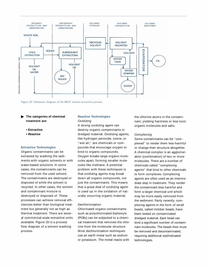
the chlorine atoms in the contami-nant, yielding harmless or less toxicorganic molecules and salts.
ComplexingSome contaminants can be “com-plexed” to render them less harmfulor change their structure altogether.A chemical complex is an agglomer-ation (combination) of two or moremolecules. There are a number ofchemicals called “complexingagents” that bind to other chemicalsto form complexes. Complexingagents are often used as an interme-diate step in treatment. They renderthe contaminant less harmful andform a larger chemical unit whichmay be more easily removed fromthe sediment. Fairly recently, com-plexing agents in the form of smallbeads, called imbiber beads, havebeen tested on contaminateddredged material. Each bead canbind a significant number of contami-nant molecules. The beads then mustbe removed and decontaminated,requiring additional sophisticatedtechnologies.
Reactive Technologies
OxidizingA strong oxidizing agent candestroy organic contaminants indredged material. Oxidizing agents,like hydrogen peroxide, ozone, or“wet air,” are chemicals or com-pounds that encourage oxygen tobind to organic compounds.Oxygen breaks large organic mole-cules apart, forming smaller mole-cules like methane. A potentialproblem with these techniques isthat oxidizing agents may breakdown all organic compounds, notjust the contaminants. This meansthat a great deal of oxidizing agentis used up in the oxidation of nat-urally occurring organic material.
DechlorinizationChlorinated organic contaminantssuch as polychlorinated biphenyls(PCBs) can be subjected to a chemi-cal treatment that removes the chlo-rine from the molecular structure.Most dechlorinization techniquesuse an earth metal such as sodiumor potassium. The metal reacts with
� The categories of chemical
treatment are:
• Extractive
• Reactive
Extractive Technologies
Organic contaminants can beextracted by washing the sedi-ments with organic solvents or withwater-based solutions. In somecases, the contaminants can beremoved from the used solvent.The contaminants are destroyed ordisposed of while the solvent isrecycled. In other cases, the solventand contaminant mixture isdestroyed or disposed of. Theseprocesses can achieve removal effi-ciencies better than biological treat-ment but generally not as high asthermal treatment. There are sever-al commercial-scale extractive unitsavailable. Figure 20 is a processflow diagram of a solvent washingprocess.
Figure 20: Schematic diagram of the BEST solvent extraction process
EV
AP
OR
AT
OR
RE
SO
UR
CE
CO
NS
ER
VAT
ION
CO
MPA
NY,
199
4

Thermal Treatment
Dredged materials or residues fromother types of treatment that are veryseriously contaminated with organicmaterial may be treated thermally.Thermal treatment techniques areoften expensive, but they can achievevery high removal and destructionefficiencies. In theory, thermal treat-ment can destroy or remove allorganic contaminants and mercury.Metals (other than mercury) cannotbe treated with thermal destructionor removal systems, however, vit-rification (see below) does bindmetals into a glass-like product.
EmissionsThermal treatment systems producegas and liquid waste that must bemanaged carefully. Emissions com-mon to all the techniques are dis-cussed here. Emissions specific to atechnology are discussed in the sec-tion for that technology.
Thermal processes create gases.Some are condensed and treated incooling systems. Ultimately someare released to the environmentafter cooling, scrubbing (see Justin Case: Saftey Features, p. 35) andfiltering. If the equipment is notoperated properly or if a systemfailure occurs, air emissions can besignificant. Dioxins and furans areof special concern. If chlorinatedorganics are present in the feedsediment, dioxins and furans couldbe emitted to the air. Two of thefour types of thermal treatmenttechnologies discussed below havethe potential to create dioxins andfurans: incineration and vitrification.Since no oxygen is present in ther-mal desorption or reduction, nodioxins or furans are produced.
Liquid wastes from thermal processesinclude water condensed from the
off-gas and cooling water. Whenscrubbers are used to clean airemissions, scrubber water becomesa waste as well. All liquid wastemust be treated before it is disposedor released to receiving waters.
Monitoring RequirementsMonitoring of thermal treatmenttechnologies is fairly straight-for-ward but must be done on a“mass-balance” basis. This meansthat all inputs and outputs must beweighed and analyzed for contami-nant concentrations, and all internalsurfaces of the equipment must beinspected or sampled before andafter the treatment. Monitoring ofany thermal process can be expen-sive, especially if dioxins andfurans are to be monitored.
� There are four types of
thermal treatment:
• Thermal Desorption;
• Incineration;
• Thermal Reduction; and
• Vitrification.
Thermal Desorption
Thermal desorption uses heat toturn organic contaminants andmercury, a volatile metal, intogases and remove them from thesolid portions of the sediment.The toxic gases are condensed andcollected as a liquid residue ofsubstantially less volume than theoriginal sediment. Although thistechnology does not destroy thecontaminants, the remaining volumeof contaminated liquid requiringfurther treatment is much smaller,thus reducing the costs of subse-quent treatment or disposal.
Does It Work?In theory, thermal desorbers canremove all organic contaminantsfrom all sediments. All organicmolecules become vapors (volatilize)at temperatures above approxi-mately 600oC. Most thermal desor-bers are designed to reach thistemperature. In practice, however,thermal desorbers have difficultytreating very fine-grained (clay)sediments because the spacesbetween the particles are so small
Thermal Desorption
EPA, GREAT LAKES NATIONAL PROGRAM OFFICE

that the contaminants cannotescape. It is also difficult maintainingconsistent temperatures across allof the sediments being treated.
EmissionsThere is little or no possibility thatdioxins and furans will be formedinside the desorption chamberbecause no oxygen is present.However, thermal desorbers canproduce significant particulate emis-sions that must be captured.
Size and Setup TimeThe technology is made to beportable and reusable but can becomplex to set up. For small jobsthe setup might take a month orless and for large jobs setup couldtake 2-4 months. Generally speakingthermal desorption units do nothave a large footprint. The entireunit may fit in two or three tractor-trailers and take up 1-2 acres whenset up.
Treatment RateMost treatment units operate at 5-10tons per hour but systems are avail-able that can treat at up to 50 tonsper hour.
CostRecently, thermal desorption costshave dropped dramatically. Somethermal desorbers are now pricedcompetitively with landfills and bio-logical treatment. The cost is typi-cally between $35 and $100 per ton(approximately $55 and $150 percubic yard) of sediment.
The ATP thermal desorption technology was demonstrated at the Wide BeachDevelopment Superfund Site, in Brant, New York, in 1991. Three test runs were per-formed with a pilot scale unit. PCB contaminated soil and sediment was treated tobelow 2 ppm (the project objective) in each test run. In fact, the average PCB concentra-tion in the treated sediment and soil was 0.043 ppm. No breakdown organic productswere detected in the treated soil and no dioxins or furans were detected in stack gases.
Pros
• If operated properly shouldnot have air emission prob-lems.
• Very effective (in theory) formost contaminants and mosttypes of sediments.
• Low cost compared to otherthermal techniques.
• No possibility of dioxin orfuran production.
Cons
• Has difficulty with fine-grained sediment.
• Prone to process upsets andbreakdowns.
• Can produce bad air emis-sions if not operated properlyor if emission controls not inplace.
• Need to remove as muchwater as possible from sedi-ment before treatment.
T H E R M A L D E S O R P T I O N
Figure 21: Process flow diagram of the
XTRAX thermal desorber.
CH
EM
ICA
L WA
ST
E M
AN
AG
EM
EN
T 1993

Incineration
Incineration is currently used todispose of both hazardous andmunicipal wastes. Incinerators burntrash, dredged material, or otherwaste streams, destroying allorganic matter. However, existinghazardous and municipal wasteincinerators are a major source ofdioxins, furans, mercury, and otherhazardous air pollutants.
Sediment Conditions andContaminantsAll types of sediment can be incin-erated, though clay can sometimespose a challenge. Sediments mustbe dewatered before they areincinerated.
Does It Work?Incinerators can destroy essentiallyall organic contaminants from allsediments. Incinerators operate atvery high temperatures. If sedimentsstay in the incineration chamberlong enough, all organic moleculesburn. In practice, however, incinera-tors have difficulty treating veryfine-grained (clay) sedimentsbecause the clay forms lumps andhardens in the heat. Fluidized bedincinerators try to solve this prob-lem by blowing air or another gasthrough the sediment to preventlumps from forming. Incinerationdoes not destroy metals. Mercuryvolatilizes and must be removedfrom the stack gas. Other metalsremain in the burned remains of thesediment and must be disposed.
Emissions Dioxins and furans will be pro-duced during the incinerationprocess. Afterburners can reducedioxin and furan emissions enoughto meet air emissions standards,but they cannot completely elimi-nate dioxin and furan emissions.An afterburner is a second burner
unit that burns any organic mole-cules in the off-gases from the firstburner. The burned remains of sed-iment contain heavy metals andother toxic chemicals and must bedisposed of properly. Monitoring ofincineration is usually carried outby firms that specialize in monitor-ing as monitoring of stack gasesmust be done in a precise manner.
Size and Setup TimeIncinerators are usually considered“transportable” not portable. Thismeans they are large and can becomplex to set up. For small jobsthe setup might take a few monthsor less but for large jobs setupcould take 6-12 months. Generallyspeaking incinerators do not take uptoo much land, although they maybe rather large facilities. The systemmay occupy 1-2 acres of land.
Pros
• Designed to meet 99.9999%destruction requirement.
• Very effective for most con-taminants and most types ofsediments.
Cons
• May have difficulty with fine-grained sediment (certain typesof incinerators).
• Prone to process upsets andbreakdowns.
• Can have bad air emissions ifnot operated properly or ifemission controls not in place.
• Need to remove as muchwater as possible from sedi-ment before treatment.
• Expensive when compared toother treatment types.
• May produce dioxins andfurans.
I N C I N E R A T I O N
Treatment RateMost treatment units operate at 5-10 tons per hour but systems areavailable that can treat at up to 50tons per hour.
CostBecause the energy requirementsfor incinerators are high and airemission requirements are strict,incinerators tend to be the mostexpensive type of treatment.Incineration typically costsbetween $300 and $900 per ton(approximately $500 and $1350per cubic yard) of sediment.
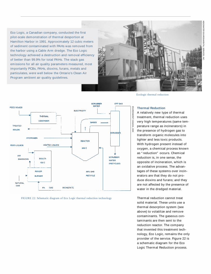
Thermal Reduction
A relatively new type of thermaltreatment, thermal reduction usesvery high temperatures (same tem-perature range as incinerators) inthe presence of hydrogen gas totransform organic molecules intolighter and less toxic products.With hydrogen present instead ofoxygen, a chemical process knownas “reduction” occurs. Chemicalreduction is, in one sense, theopposite of incineration, which isan oxidative process. The advan-tages of these systems over incin-erators are that they do not pro-duce dioxins and furans; and theyare not affected by the presence ofwater in the dredged material.
Thermal reduction cannot treatsolid material. These units use athermal desorption system (seeabove) to volatilize and removecontaminants. The gaseous con-taminants are then sent to thereduction reactor. The companythat invented this treatment tech-nology, Eco Logic, remains the onlyprovider of the service. Figure 22 isa schematic diagram for the EcoLogic Thermal Reduction process.
Ecologic thermal reduction
FIGURE 22: Schematic diagram of Eco Logic thermal reduction technology
Eco Logic, a Canadian company, conducted the firstpilot-scale demonstration of thermal desportion atHamilton Harbor in 1991. Approximately 12 cubic metersof sediment contaminated with PAHs was removed fromthe harbor using a Cable Arm dredge. The Eco Logictechnology achieved a destruction and removal efficiencyof better than 99.9% for total PAHs. The stack gasemissions for all air quality parameters measured, mostimportantly PCBs, PAHs, dioxins, furans, metals andparticulates, were well below the Ontario’s Clean AirProgram ambient air quality guidelines.
EN
VIR
ON
ME
NT
CA
NA
DA
, 2000
HE
AD
WA
TE
R E
NV
IRO
NM
EN
TAL S
ER
VIC
ES
, INC
.

jobs the setup might take a fewmonths or less but for large jobssetup could take 6-12 months.Generally speaking thermal reduc-tion units do not have a large foot-print. The system may occupy 1-2acres of land.
Treatment RateThe smallest thermal reductionunits operate at 5 tons per hour butunits can be built to handle up to50 tons per hour.
CostThe cost is typically between $150and $350 per ton (approximately$225 and $525 per cubic yard) ofsediment.
Vitrification
Vitrification heats up sediments likean incinerator, forcing organic con-taminants and mercury out of thesediments in a gaseous state anddestroying them either in the pri-mary chamber or in an afterburner.Mercury must be captured andscrubbed from the off-gas. Thetechnique also immobilizes othermetal contaminants, a distinctadvantage in some situations. Theprocess runs at a temperature highenough to melt sand and metals inthe dredged material (>900oC). Aftercooling, the dredged material turnsinto a hard slag-like product thattraps the metals permanently. Mosttechnologies in this category pro-duce a product such as gravel orbricks which can be used as build-ing material. A disadvantage of vit-rification is the high energy con-sumption and the flue-gas emis-sions produced. Vitrification hasrarely, if ever, been used at fullscale in North America, thoughseveral bench-scale and pilotscale demonstrations have beenperformed.
process because there is no oxygenpresent in the reactor.
The Eco Logic company has devel-oped an “on-line” monitoring sys-tem that is used mainly to controlthe process but is a great help tothe environmental monitoring.
Sediment Conditions andContaminantsSediments do not have to be dewa-tered for thermal reduction to thesame extent as for other thermalprocesses. Fine grained sedimentscan pose a challenge to the thermaldesorber because the spacebetween the particles is so smallthat it is difficult for the contami-nants to pass through the spacesand out of the sediment.
Size and Setup TimeThis technology is usually consid-ered “transportable” not portable.This means they are large and canbe complex to set up. For small
Does It Work?Thermal reduction systems can, intheory, destroy all organic contami-nants from all sediments. In prac-tice, thermal reduction systems arelimited by the quality of the thermaldesorption system used to removethe organic molecules from thesediment (see discussion of limita-tions of thermal desorbers above).Heavy metals, with the exception ofmercury, cannot be treated withthermal reduction. Heavy metalsremain in the sediments after thethermal desorption part of theprocess. Mercury is removed in thedesorption process.
EmissionsAir emissions can be recycled tothe reactor to further reduce anyremaining organic molecules. If theequipment is not operated properlyor if a system failure occurs, airemissions can be significant.Dioxins and furans can never beproduced during the treatment
Pros
• If operated properly shouldnot have air emission problems.
• Very effective (in theory) formost contaminants and mosttypes of sediments.
• Can achieve 99.9999%destruction for some contami-nants in some situations.
• No possibility of dioxin orfuran production.
• Water in the sediment doesnot affect the process.
Cons
• May have difficulty with fine-grained sediment.
• Prone to process upsets andbreakdowns.
• Relatively expensive comparedto other technologies.
• Depends on the performanceof the thermal desorber (thefirst step in the process) for theoverall treatment efficiency.
T H E R M A L R E D U C T I O N

Does It Work?Vitrification systems can remove ordestroy all organic contaminantsfrom all sediments. They operate atvery high temperature, and if theresidence time (time in the heatingchamber or afterburner) is longenough all organic molecules willoxidize (burn). Metal contaminantsare trapped in the vitrified material.
EmissionsVitirification systems with an “after-burner” (a second burner unit thatburns any organic molecules in theoff-gases from the first burner)should be able to meet the moststringent air emissions standards.Dioxins and furans may be producedduring the vitirification process.
Sediment Conditions andContaminantsVitirification systems do not havethe same problem with fine grainedsediments as other thermal treat-ment systems do.
Size and Setup TimeThese systems are usually consid-ered “transportable” not portable.This means they are large and canbe complex to set up. For small jobsthe setup might take a few monthsor less but for large jobs setupcould take 6-12 months. Generallyspeaking vitrification units do nothave a large footprint. The systemmay occupy 1-2 acres of land.
Treatment RateVitirification systems can bedesigned to treat from 5-50 tonsper hour.
CostNot enough projects have beendone to establish a price range Apilot project in Wisconsin indicatesthat at full scale the cost could beless than $40-60 per ton ($60-90per cubic yard).
Pros
• If operated properly shouldnot have air emission prob-lems.
• Very effective (in theory) formost contaminants and mosttypes of sediments.
• Immobilizes non-volitilemetals in the vitrified sediment.
Cons
• Prone to process upsets andbreakdowns.
• Can have bad air emissions ifnot operated properly or ifemission controls not in place.
• Need to remove as muchwater as possible from sedi-ment before treatment.
• May produce dioxins andfurans.
V I T R I F I C A T I O N
Minergy vitrification pilot project, Winneconne, WI
WI D
EPA
RT
ME
NT
OF
NA
TU
RA
L R
ES
OU
RC
ES

most types of metals. Anothertechnique uses a silica solution to“encapsulate” contaminants thatare bound to sediment particles.This technique is not always effec-tive – especially with high levels oforganic contamination.
Solidification – Solidification uses acementing substance or high-tem-perature melting (see Vitrificationsection above) to encapsulate andstabilize contaminants. After theaddition of a cementing substance,the dredged material can beallowed to harden in a large massin a fill site or formed into smallerblocks or bricks.
Does It Work?The main disadvantage of immobi-lization techniques, and the reasonmany countries do not allow immo-bilized dredged material to be usedas construction material, is that thecontaminants remain in the
Immobilization by Fixation
or Solidification
Immobilization attempts to lockcontaminants in the dredged mate-rial either by chemically binding thecontaminants to the solid particles(fixation) or physically preventingthe contaminants from moving(solidification). In some cases, acombination of physical and chemi-cal immobilization is used. Afterthis type of treatment, the dredgedmaterial is usually placed in a dis-posal site or used as a constructionmaterial (where allowed by law).
Fixation – Fixation techniques focuson chemically binding contaminantsto prevent them from entering theenvironment. There are a numberof different approaches to fixation.One involves adding large quanti-ties of chemicals that raise the pHof the material, making it morealkaline, and thus immobilizing
Product of cement-lock process
Pros
• If carried out properly shouldnot have air emission prob-lems; if volatile emissions are aproblem then these can be con-trolled with containment andtreatment systems.
• Very effective (in theory) atreducing the leaching of con-taminants for most contami-nants and most types of sedi-ments.
• Low cost.
• Easy to implement.
• May be able to produce con-struction materials with treatedsediment.
Cons
• Does not destroy the contami-nants – this may be a long-termconcern.
• May be difficult to gainapproval or to find a disposalsite for treated material.
• Can have bad air emissions ifnot operated properly or ifemission controls not in place.
• Difficult to predict the longevi-ty of the fixation or solidifica-tion. If the conditions change atthe disposal site (pH, tempera-ture, oxidation-reduction poten-tial, leaching rate) then theeffectiveness of the treatmentmay be impaired.
I M M O B I L I Z A T I O N
dredged material. The effectivenessof immobilization may be short-term. Contaminants may leachfrom the material after a number ofyears. However, the leachable frac-tion of the contaminants can bereduced by at least 99% in theshort-term.
EmissionsAdding chemicals to contaminatedsediment can cause unpredictableresults. If the sediment is not uni-form, the chemical reaction pro-duced will not be uniform. Thiscommonly results in an unexpect-edly large release of volatile organ-ic compounds. In addition, if thesediment contains contaminantsthat are highly reactive there maybe hazardous or dangerous residu-als or emissions.
Catastrophic releases of contamina-tion, water or solids are unlikelybecause most processes are
EPA
, GR
EA
T LA
KE
S N
AT
ION
AL P
RO
GR
AM
OFFIC
E

the-shelf” equipment is used formixing the sediment and fixatives.The limiting factor may be thespace available for curing the treat-ed sediment.
CostImmobilization techniques typicallycost between $10 and $50 per ton(approximately $15 and $75 percubic yard), not including the costof disposal.
“batch” processes. One batch istreated at a time in a relatively con-trolled environment. The chemicaladditives themselves may havesome dangerous properties. Theyare often extremely acidic,extremely alkaline or extremelyreactive. If the correct dose ofchemicals is added, the end resultshould be a relatively neutral andinert material.
It is easy to monitor the processand perform leachate tests on thetreated material. It is difficult toanalyze the treated material todetermine if contaminants havebeen destroyed (as some vendorsclaim), or are merely bound in thesediment.
Sediment Conditions andContaminantsFixation and stabilization can beused on any type of contaminant intheory, but in reality they are diffi-cult to use for very high concentra-tions of organic contaminants. Anytype of sediment may be treated aslong as additives can be specificallytailored to work with the particularmix of sediment and contaminants.
Size and Setup TimeTypically the processes are verymobile and easily set-up anddecommissioned. For small jobs asystem could be set-up in one totwo weeks. Generally speaking fixa-tion/stabilization processes do nothave a large footprint. The entireunit may fit in one or two tractor-trailers. Large amounts of spacemay be required to cure the treatedmaterial, but the treated materialcan also go directly to the disposalarea.
Treatment RateThe process can be designed totreat at almost any rate since “off-
JIM
GR
IND
RO
D

It is clear: we have the tools and knowledge to clean
up toxic sediment sites. The time to act is now. The
legacy of industrial pollutants at the bottom of Great
Lakes rivers and harbors is a major barrier to a healthy
ecosystem and sustainable economy. Fixing this prob-
lem will require time and money, but the dividends of
this investment, measured in economic growth and
environmental health, will be well worth the cost. The
alternative—doing nothing—is not acceptable.
Residents and visitors of the Great Lakes region have
lived with that alternative for more than 30 years and
continue to suffer its effects every day.
This guide, along with the other resources described in
the Appendices, provides an overview of the tools and
techniques we can use to get cleanups underway. It is
time to put these tools to good use. Using these
resources, we can help assemble and evaluate cleanup
plans. We can make informed decisions and have con-
structive dialogues with regulators and communities.
We can invest in permanent solutions to toxic prob-
lems by testing and developing treatment technolo-
gies. We can leave our children water that is safe for
fishing and swimming and harbors that promote eco-
nomic growth. We can achieve our vision of a healthy
aquatic ecosystem that supports a vibrant, sustainable
economy throughout the Great Lakes basin. Now we
simply must generate the will to take action and start
down the road to healthy harbors and restored rivers.
moving forward

Appendix A:
Roadmap to Remediation

Significant environmental
resources to be protected
• State resource agencies• U.S. Fish & Wildlife Service
State and local environmental
regulations
• State resource agencies• County departments of health• Local agencies (departments
of zoning, transportation orenvironment)
• Impacts of contaminants onhuman health and theenvironment
• Remedial Investigation• State resource agencies• U.S. Fish & Wildlife Service• Natural resources damage
assessment (NRDA)
Adapted from USEPA. 1994a. Assessment andRemediation of Contaminated Sediments(ARCS) Program, Final Summary Report.Publication EPA 905-S-94-001.
Appendix B:
Where can I find the
information I need?
Volume and distribution of
contaminated sediments
• Remedial Investigation(Superfund Site Assessment)
• Remedial Action Plans• USEPA or Corps district offices• State resource agencies
Sediment chemical and physical
characteristics
• Remedial Investigation• Remedial Action Plans• USEPA, Corps, or other Federal
agencies• State resource agency
Waterway bathymetry and
hydraulic characteristics
• Remedial Investigation• Navigation charts from the
National Oceanic and AtmosphericAdministration, the U.S. CoastGuard, or the Corps Floodcontrol/insurance studies by theFederal Emergency ManagementAgency or the Corps
• State resource agencies• Local harbor/port authorities
Waterway navigation use
• Waterborne Commerce of theUnited States (US Army Corpsof Engineers)
• U.S. Coast Guard offices• State transportation and
resource agencies• Local harbor/port authorities
Availability of local lands for use
• State transportation andresource agencies
• Local agencies (departmentsof planning, zoning or economicdevelopment)

effluent – dilute wastewaters result-ing from sediment treatment andhandling. Effluents include dis-charges, surface runoff, waste-water, etc. from a confined disposalfacility or landfill.*
erosional – describes a waterbodyor portion of a waterbody wheresediments on the bottom andbanks are scoured by movingwater. The opposite of depositional.
feasibility study – a study thatincludes evaluation of all reason-able remedial alternatives, includ-ing treatment and nontreatmentoptions.*
geotextiles – specially designedsynthetic fabrics that allow water toflow through but retain sediments.Geotextiles may be used as part ofa contaminated sediment cap or asbarriers to prevent the transport ofsediments downstream.
leachate – includes waters that haddirect contact with sediment, orprecipitation that has soaked intosediments in a confined disposalfacility or landfill.*
mobilization – the process of bring-ing construction equipment to awork site.*
natural recovery – refers to leavingsediments alone in the hopes thatnatural processes cover them upwith non-contaminated material.
oil boom – synthetic foam floatsencased in fabric and connectedwith chains or cables. Oil boomscontain oil floating at the top of awaterbody.
oxidation-reduction potential – ameasure of the amount of oxygenavailable in a substance. If oxygen
biomagnification – the increase inconcentration of a pollutant fromone link in a food chain to another.Animals low on the food chain takein pollutants and store them in theirtissue or body fat. As predators eatcontaminated prey, the pollutantsin the prey build up in the preda-tors. The predators end up withhigher concentrations of the pollu-tants in their bodies. Animals at thetop of the food chain have the high-est concentrations of pollutantsstored in their bodies.
capping – covering contaminatedsediments with clean material in aneffort to isolate them from the sur-rounding ecosystem.
chemical treatment – the use ofchemicals to destroy or immobilizepollutants in sediments.
coffer dam – a temporary, watertight enclosure built in the water.Coffer dams prevent the transportof sediments downstream duringdredging operations.
composite sample – a sample ofair, water, or solids (sediment)made up of a number of samplesmixed together. Spatial compositesamples are made up of samplestaken at roughly the same time butat different places. Temporal com-posites are taken from the sameplace at different times.
demobilization – the process ofremoving construction equipmentfrom a work site.*
depositional – describes a water-body or portion of a waterbodywhere sediments fall out of thewater and are deposited on thebottom. The opposite of erosional.
Appendix C:
Glossary
absorbent mats – mats used tosoak up oily material
Areas of Concern – forty-twogeographic areas around theGreat Lakes basin where pollutionand development have severelydamaged local ecosystems. Thegovernments of the United Statesand Canada designated the Areasof Concern in 1987.
armored caps – stone, cement,or other hard material placed overcontaminated sediments in aneffort to isolate contaminants fromthe ecosystem.
barge – a flat bottomed boat usedfor transport, similar to a scow.
beach nourishment – using sedi-ments or sand to build up a beach,replacing eroded material.
bench-scale – testing and evaluationof a treatment technology on smallquantities of sediment (several kilograms) using laboratory-basedequipment that is not directlysimilar to the full-sized equipmentthat would be used for an actualcleanup.*
benthic – pertaining to the bottomof a body of water. Benthic commu-nity refers to the micro-organisms,plants, and animals that live at thebottom of a body of water.
biological treatment – the use ofmicro-organisms or plants to treatpollutants in sediments. Micro-organisms destroy pollutants by“eating” them. Plants remove con-taminants from the sediments andstore them in their stems or leaves.

• chemical data such as concentra-tion of contaminants and naturallyoccurring chemicals, pH, biologicaloxygen demand, and oxygen avail-ability; and• biological data such as types andnumbers of animals and plantsnear the zone, biological damageobserved in animals and plants,and history of animals and plantsbefore and after contamination.
spud – retractable “leg” thatextends from the bottom of adredge to the sediments below toanchor it in place and facilitatemovement.
weir – in a Confined DisposalFacility, a pipe that carries waste-water or surface runoff to a waste-water treatment plant.
volatile substances – compoundsthat prefer to be in the gaseousstate at normal temperature andpressure. Volatile substances foundin contaminated sediment are phys-ically trapped in the pores of thematerial, dissolved in water, orattached to solid particles. Sincesediment is usually cold and undis-turbed, it can retain volatile sub-stances for a long time. If sedimentis disturbed or heated, volatilegases will escape, causing potentialhazards for site workers and theenvironment.
*Denotes definitions from USEPA. 1994a.
(or chemicals that behave like oxy-gen) are not available, then thematerial is said to be in a reducedstate.
petroleum hydrocarbons – fuelsand byproducts derived from crudeoil or coal.
pilot-scale – testing and evaluationof a sediment treatment technologywith scaled-down but essentiallysimilar processors and supportequipment as used in full-sizedoperation to treat up to severalhundred cubic meters of sediment.*
pneumatic pumps – pumps thatuse changes in air pressure tomove material from one place toanother.
resuspension – the process bywhich particles of sediment arestirred up and suspended in water.
scow – a flat-bottomed boat withsquare ends that is used to carrybulk material like sediments orsand, similar to a barge.
silt curtains – impermeable materi-al that redirects the flow of water inan effort to prevent the transport ofresuspended sediment down-stream.
silt screens – permeable materialthat lets water through but retainssediment. Used to prevent thetransport of resuspended sedimentdownstream.
site characterization – all field workleading up to remediation of a zoneof contaminated sediments. Thisincludes gathering the following data:• physical data such as water depth,water currents, sediment depth andlayering, location, temperature, andsediment type;

U.S. Environmental Protection
Agency
Remediation and Characterization
Innovative Technologies (REACH IT)
Database
http://www.epareachit.org/index3.htmlREACH IT is a comprehensive list ofexisting treatment technologies.Site users can search by technolo-gy, contaminant, media, site name,or a combination of these. REACHIT has access to information aboutthe more than 370 treatment tech-nologies provided by over 250 firms.The site provides informationregarding treatment options for fivecontaminant groups includingVOCs, SVOCs, Fuels, Inorganics,and Explosives.
U.S. Army Corps of Engineers
Center for Contaminated
Sediments
http://www.wes.army.mil/el/dots/ccs/index.htmlThe U.S. Army Corps of EngineersCenter for Contaminated Sediments(CCS), consolidates researchexpertise to deal with the problemof contaminated sediments. TheCenter coordinates and facilitatescontaminated sediment activitiesamong Corps organizations, theDepartment of Defense, other fed-eral and state agencies, academia,and the private sector.
U.S. Army Corps of Engineers
Environmental Effects of Dredging
and Disposal (E2-D2) Literature
Database
http://www.wes.army.mil/el/e2d2/Environmental Effects of Dredgingand Disposal literature databasecontains over 3,000 references per-taining to the environmental effectsof dredging and dredged disposalprojects.
International Joint Commission
Great Lakes Water Quality
Board Reports
http://www.ijc.org/boards/wqb/Canada and the United States cre-ated the International JointCommission because they recog-nized that each country is affectedby the other’s actions in lake andriver systems along the border. Thetwo countries cooperate to managethese waters wisely and to protectthem for the benefit of today’s citi-zens and future generations.
Lake Michigan Federation
http://www.lakemichigan.org
Scenic Hudson
http://www.scenichudson.org
Sierra Club
see: http://www.sierraclub.org andhttp://www.sierraclub-glp.organd the following reports areavailable from the Sierra ClubGreat Lakes Program, 214 N. HenrySt, Suite 203, Madison, WI 53703:• Clean Lakes, Clean Steel: A
Citizens’ Guide to the Great LakesSteel Industry
• Clean Lakes, Clean Sediments: ACitizens’ Guide and CommonSense Action Plan
• Clean Lakes, Clean Jobs: A Casefor Cleaning Up ContaminatedSediments
• Something’s Fishy: What youdon’t know about polluted fishcan hurt you
• Great Lakes: Great Progress, GreatChallenges; 25 Years of ProgressThanks to the Clean Water Actand Great Lakes Water QualityAgreement
Appendix D:
Additional Resources
Coast Alliance
http://www.coastalliance.org
Great Lakes Environmental
Research Laboratory (GLERL)
http://www.glerl.noaa.gov/Scientists at this federally fundedlaboratory study the biological,chemical, and physical processesthat occur in natural ecosystems,especially in the Great Lakes.GLERL has five research programsthat cover coordinated ecosystemresearch, climate variability andchange, marine hazards, pollutants,and exotic species.
Great Lakes Commission
http://www.glc.orgEight states – Illinois, Indiana,Michigan, Minnesota, New York,Ohio, Pennsylvania, and Wisconsin– formed the commission in 1955 tohelp them manage the Great Lakes.The commissions provides thestates with research, advice, andadvocacy on issues of develop-ment, use and protection of waterand land resources in the GreatLakes Basin.
International Association for Great
Lakes Research (IAGLR)
http://www.iaglr.orgThis association of sientists pub-lishes the quarterly Journal ofGreat Lakes Research and hosts anannual conference on Great Lakesresearch. Conference sessions andJournal publications cover a widerange of research airmed at under-standing the world’s large lakesand the human communitiesaround them.

Greater Boston Physicians forSocial Responsibility. Jan. 2000. InHarm’s Way: Toxic Threats to ChildDevelopment. Joint project with theClean Water Fund. Report availableon-line at http://www.igc.org/psr/
Lake Carriers Association. 1995.1994 Annual Report – 1995Objectives 23. Cleveland,OH.
Landrum, P.F, B.J. Eadie, P.L. VanHoof. 1999. “What areContaminants, Why Are They aProblem?” Great LakesEnvironmental ResearchLaboratory, Ann Harbor, MI.http://www.glerl.noaa.gov/pubs/brochures/wcontflyer/wcont.html
Miller, J. April 2000. PersonalCommunication. EnvironmentalEngineer, Army Corps of Engineers.
Miller, J. May 2001. PersonalCommunication. EnvironmentalEngineer, Army Corps of Engineers.
National Research Council. 1997.Contaminated Sediments in Portsand Waterways. National AcademyPress, Washington, DC.
Netherlands Institute for WaterManagement and Waste WaterTreatment. 1992. DevelopmentProgramme Treatment Processes,Phase I.
Normrock Industries Inc. 1995-2000.“Amphibious Excavator(Amphibex).” http://www.enviroac-cess.ca/fiches/F1-10-96a.html
Permanent InternationalAssociation of NavigationCongresses (PIANC). 1996.Handling and Treatment ofContaminated Dredged Materialfrom Ports and Inland Waterways,Vol. 1 and 2. Report of PTC 1,
“Choice of Dredging Technique andApplication.”http://home.egenet.com.tr/~ozkasapm/engineering/dredgers/contred.html
Cleland, J. Oct. 2000. Results of Contaminated SedimentCleanups Relevant to the HudsonRiver: An Update to ScenicHudson’s Report Advances inDredging Contaminated Sediment.Scenic Hudson, Poughkeepsie, NY.
Cognis Inc. 1993. Cognis TerraMetMetal Extraction Phase I and IITreatability Studies, St. Mary’sRiver Sediment. Report submittedto Environment Canada in fulfilmentof contract.
Colborn, T., D. Dumanoski, and J.P.Meyers. 1996. Our Stolen Future.Penguin Books USA Inc, New York,NY.
Colborn, T. et. al. 1990. Great Lakes,Great Legacy? Washington D.C.Conservation Foundation,Washington D.C.
Delta Institute. 2000. AtmosphericDeposition of Toxics to the GreatLakes: Integrating Science and Policy.The Delta Institute, Chicago, IL.
Ellicott International. 2000. “NewMud Cat™ MC-2000 Dredge Used toComplete Successful PCB Clean-Upfrom Fox River, Ahead of Schedule.”http://www.dredge.com/casestud-ies/foxriver.htm
Environment Canada. 2000.Contaminated Sediment TreatmentTechnology Program (CoSTTeP).Report available from EnvironmentCanada, Great Lakes SustainabilityFund, 867 Lakeshore Rd.,Burlington, Ontario, Canada, L7R4A6.
U.S. Environmental Protection
Agency
Great Lakes National Program
Office, Contaminated Sediments
Program
http://www.epa.gov/glnpo/sediments.html
U.S. Environmental Protection
Agency
Hazardous Waste Clean Up
Information (CLU-IN)
http://clu-in.org/CLU-IN provides excellent descrip-tions of several remediation treat-ment types including ThermalDesorption, Soil Washing,Phytoremediation, Bioremediationand Clean Oxidation.
U.S. Environmental Protection
Agency
Assessment and Remediation of
Contaminated Sediments (ARCS)
Program Publications
http://www.epa.gov/glnpo/arcs/arcsguide.htmlThis site provides a more in-depthguide to contaminated sedimentoptions.
References
Anderson, H.A. Oct. 1996.“Awareness of Sport Fish HealthAdvisories.” Presented at Mercuryin the Midwest: Current Status andFuture Directions.
Aulerich, R.J., R.K.Ringer. 1977.“Current Status of PCB Toxicity toMink, and Effect on TheirReproduction.” Arch. Environ.Contamin. Toxicol. Vol 6 :279-292.
Chemical Waste Management. 1993.X*TRAX Low Temperature ThermalDesorption Treatability Study onThunder Bay Harbour Sediment.Report submitted to EnvironmentCanada in fulfilment of contract.
Determination Plan for the LowerFox River. Prepared by StratusConsulting in Boulder CO.
Wardlaw, C. 1994. “Overview of BioRemediation Technologies forContaminated Sediments”. Paperpresented at the Air and WasteManagement Association, OntarioSection, Conference, Oct. 19-20,1994, Toronto, Ontario.
Wardlaw, C., D. Brendon and W.Randle. 1995. “Results of Canada’sContaminated Sediment TreatmentTechnology Program.” Paper pre-sented at Sediment Remediation 95Conference, May 8-10, 1995,Windsor, Ontario, Canada.
Wisconsin DNR. February 1997.PCB Contaminated Sediment in theLower Fox River: ModelingAnalysis of Selective SedimentRemediation. PUBL-WT-482-97
Wisconsin DNR. February 1999.Draft Feasibility Study, Lower FoxRiver, Wisconsin. Prepared byThermoRetec ConsultingCorporation.
US Department of Health andHuman Services, Public HealthService, Agency for ToxicSubstances and Disease Registry.Nov. 2000. Toxicological Profile ForPolychlorinated Biphenyls (PCB’s).Prepared by the Syracuse ResearchCorporation.
USEPA. 2001. “Forum on ManagingContaminated Sediments atHazardous Waste Sites.” Forumheld May 30- June 1, 2001 inAlexandria, VA.
USEPA. 2000. Introduction toPhytoremediation. EPA/600/R-99/107. Office of Research andDevelopment, Washington, D.C.
USEPA. 1999. “ContaminatedSediments: An Overview.”www.epa.gov/ost/cs/aboutcs/overview.html
USEPA. 1994a. Assessment andRemediation of ContaminatedSediments (ARCS) Program, FinalSummary Report. Publication EPA905-S-94-001.
USEPA. 1994b. Assessment andRemediation Of ContaminatedSediments (ARCS) ProgramRemediation Guidance Document.Publication 905-R94-003.
USEPA Great Lakes NationalProgram Office. 2001. Workshop onTreating Great Lakes ContaminatedSediment. Workshop held April 24-25, 2001 in Ann Arbor, MI.
US Fish and Wildlife Service. 1999.Recreational Fishing Damages fromFish Consumption Advisories In theWaters of Green Bay. Prepared byStratus Consulting in Boulder, CO.
US Fish and Wildlife Service. 2000.Restoration and Compensation
Working Group 17. Available fromPIANC, Graaf de Ferraris, 11th Fl,Box 3, 20 Boulevard du Roi AlbertII, 1000 Brussels, Belgium.
Resources Conservation Company.1994. B.E.S.T. Bench ScaleTreatability Final Report, ThunderBay Harbour Site. Report submittedto Environment Canada in fulfilmentof contract.
Sediment Priority ActionCommittee. March 2000.“Identifying and Assessing theBenefits of Contaminated SedimentCleanup.” Prepared for theInternational Joint Commission’sBiennial Public Forum inMilwaukee. ISBN 1-894280-18-0.
Stokman, G.N.M. 1995. “TheNetherlands DevelopmentProgramme for Treatment Processesfor Polluted Sediments (POSW).” Inproceedings of seminarRemediation of ContaminatedSediments, November, 1995,Maastricht, Netherlands.
Sullivan, J. and A. Bixby. 1989. ACitizen’s Guide: Cleaning upContaminated Sediment. Supportedby the Charles Stewart MottFoundation. Lake MichiganFederation, Chicago, IL.
University of New Orleans. June20, 2000. “Shipyard EnvironmentalDredge Technology User’s Guide.”Funded by Gulf Coast RegionMaritime Technology Center.http://www.uno.edu/~engr/meric/MDDraftUsersGuide.html
US Army Corps of Engineers.“Portland District Channels andHarbors Project.”http://www.nwp.usace.army.mil/op/N/DREDGES.HTM (oregon link)

Explore, enjoy and protect the planet.
Never doubt that a small
group of thoughtful,
committed citizens can
change the world. Indeed,
it’s the only thing that ever has.
—Margaret Mead