Headlight Removal & Installation: MBZ W203 (2005 C230) · PDF fileHeadlight Removal &...
12
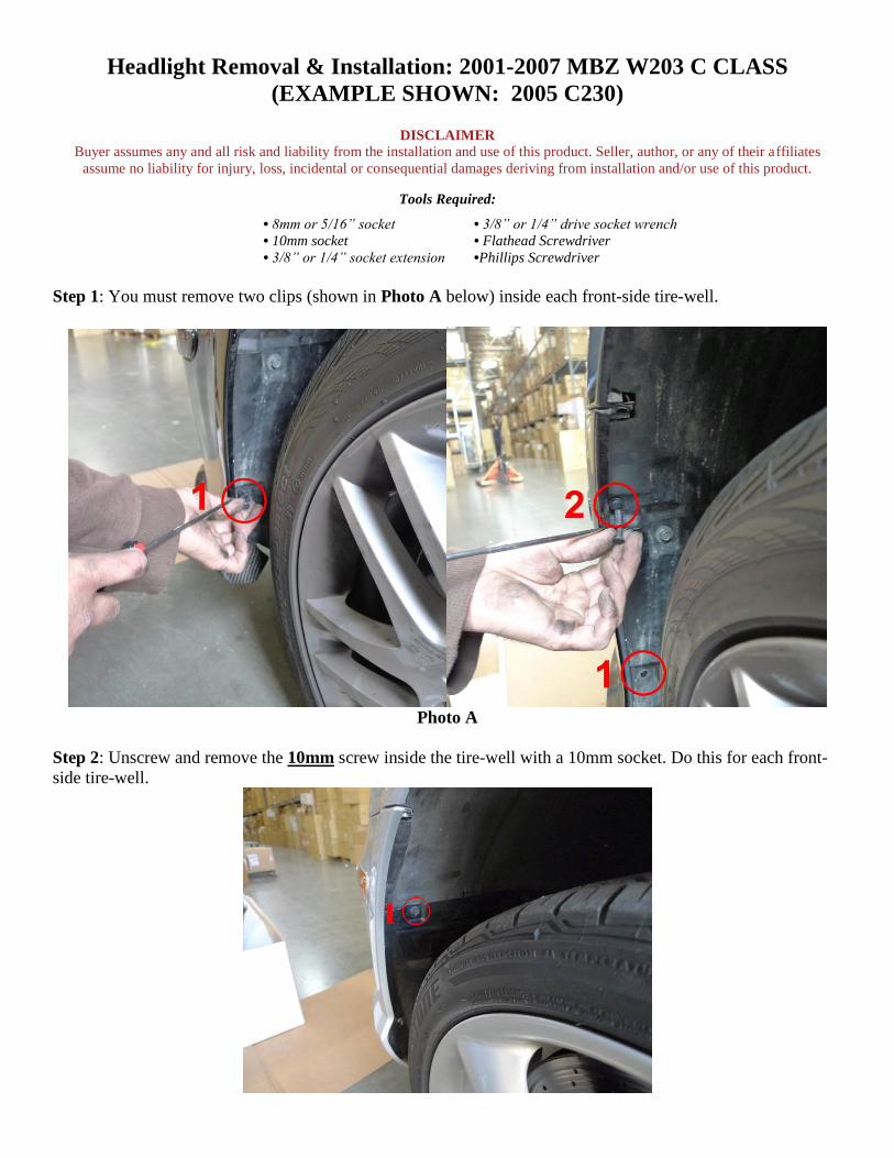
Headlight Removal & Installation: 2001-2007 MBZ W203 C CLASS (EXAMPLE SHOWN: 2005 C230) DISCLAIMER Buyer assumes any and all risk and liability from the installation and use of this product. Seller, author, or any of their affiliates assume no liability for injury, loss, incidental or consequential damages deriving from installation and/or use of this product. Tools Required: • 8mm or 5/16” socket • 3/8” or 1/4” drive socket wrench • 10mm socket • Flathead Screwdriver • 3/8” or 1/4” socket extension •Phillips Screwdriver Step 1: You must remove two clips (shown in Photo A below) inside each front-side tire-well. Photo A Step 2: Unscrew and remove the 10mm screw inside the tire-well with a 10mm socket. Do this for each front- side tire-well.
Transcript of Headlight Removal & Installation: MBZ W203 (2005 C230) · PDF fileHeadlight Removal &...
Headlight Removal & Installation: 2001-2007 MBZ W203 C CLASS
(EXAMPLE SHOWN: 2005 C230)
DISCLAIMER
Buyer assumes any and all risk and liability from the installation and use of this product. Seller, author, or any of their affiliates
assume no liability for injury, loss, incidental or consequential damages deriving from installation and/or use of this product.
Tools Required:
• 8mm or 5/16” socket • 3/8” or 1/4” drive socket wrench
• 10mm socket • Flathead Screwdriver
• 3/8” or 1/4” socket extension •Phillips Screwdriver
Step 1: You must remove two clips (shown in Photo A below) inside each front-side tire-well.
Photo A
Step 2: Unscrew and remove the 10mm screw inside the tire-well with a 10mm socket. Do this for each front-
side tire-well.
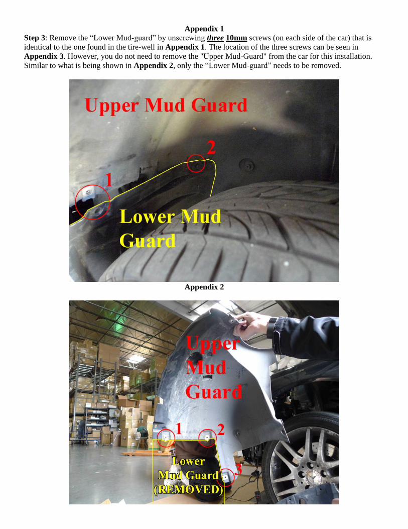
Appendix 1
Step 3: Remove the “Lower Mud-guard” by unscrewing three 10mm screws (on each side of the car) that is
identical to the one found in the tire-well in Appendix 1. The location of the three screws can be seen in
Appendix 3. However, you do not need to remove the "Upper Mud-Guard" from the car for this installation.
Similar to what is being shown in Appendix 2, only the “Lower Mud-guard” needs to be removed.
Appendix 2
Appendix 3
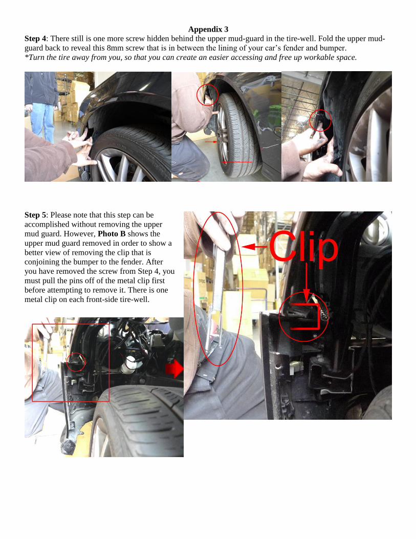
Step 4: There still is one more screw hidden behind the upper mud-guard in the tire-well. Fold the upper mud-
guard back to reveal this 8mm screw that is in between the lining of your car’s fender and bumper.
*Turn the tire away from you, so that you can create an easier accessing and free up workable space.
Step 5: Please note that this step can be
accomplished without removing the upper
mud guard. However, Photo B shows the
upper mud guard removed in order to show a
better view of removing the clip that is
conjoining the bumper to the fender. After
you have removed the screw from Step 4, you
must pull the pins off of the metal clip first
before attempting to remove it. There is one
metal clip on each front-side tire-well.
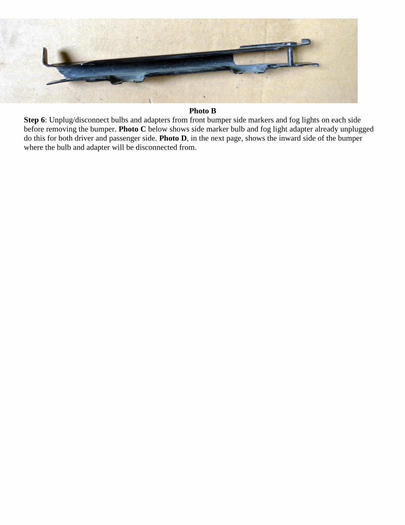
Photo B
Step 6: Unplug/disconnect bulbs and adapters from front bumper side markers and fog lights on each side
before removing the bumper. Photo C below shows side marker bulb and fog light adapter already unplugged
do this for both driver and passenger side. Photo D, in the next page, shows the inward side of the bumper
where the bulb and adapter will be disconnected from.
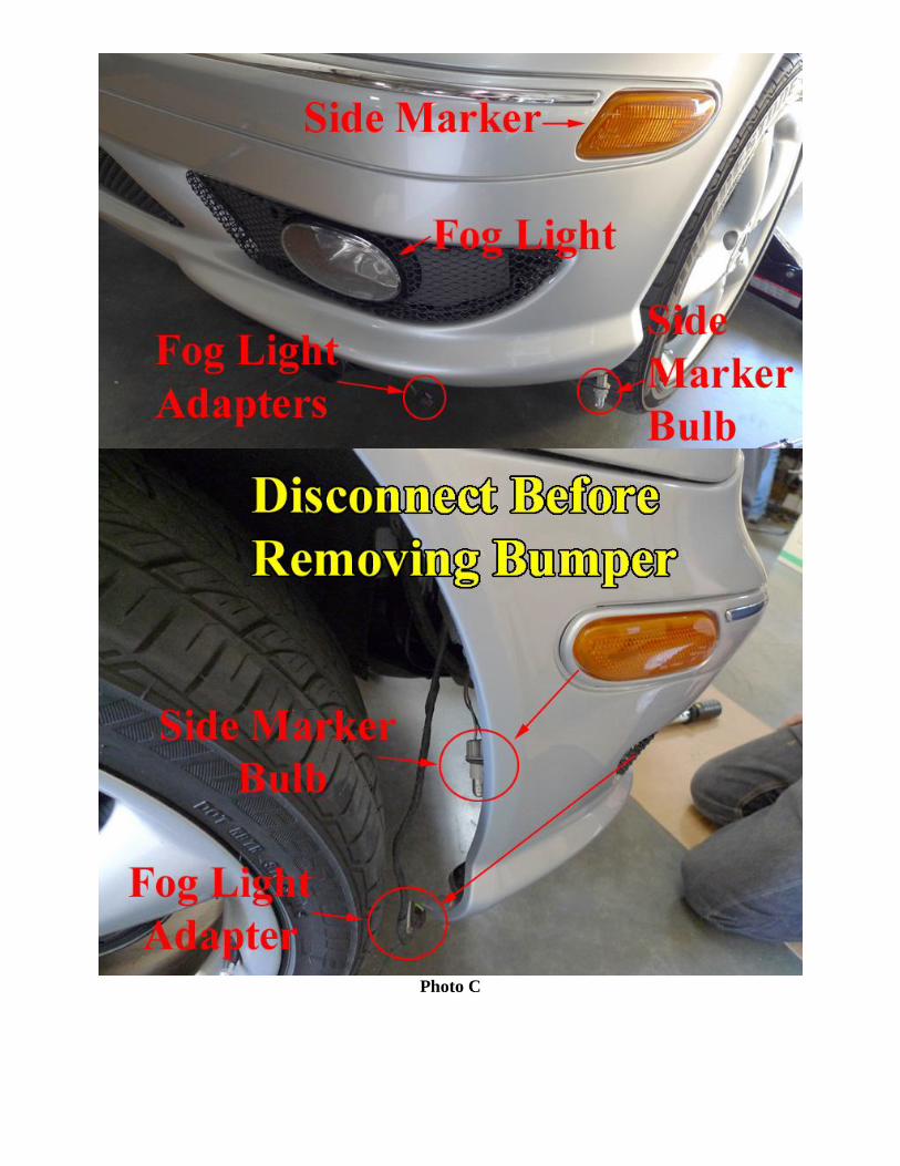
Photo C
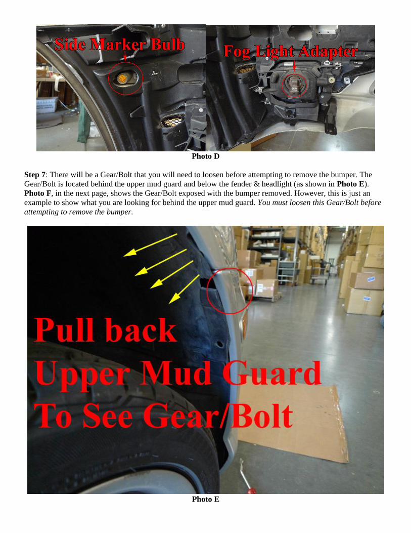
Photo D
Step 7: There will be a Gear/Bolt that you will need to loosen before attempting to remove the bumper. The
Gear/Bolt is located behind the upper mud guard and below the fender & headlight (as shown in Photo E).
Photo F, in the next page, shows the Gear/Bolt exposed with the bumper removed. However, this is just an
example to show what you are looking for behind the upper mud guard. You must loosen this Gear/Bolt before
attempting to remove the bumper.
Photo E
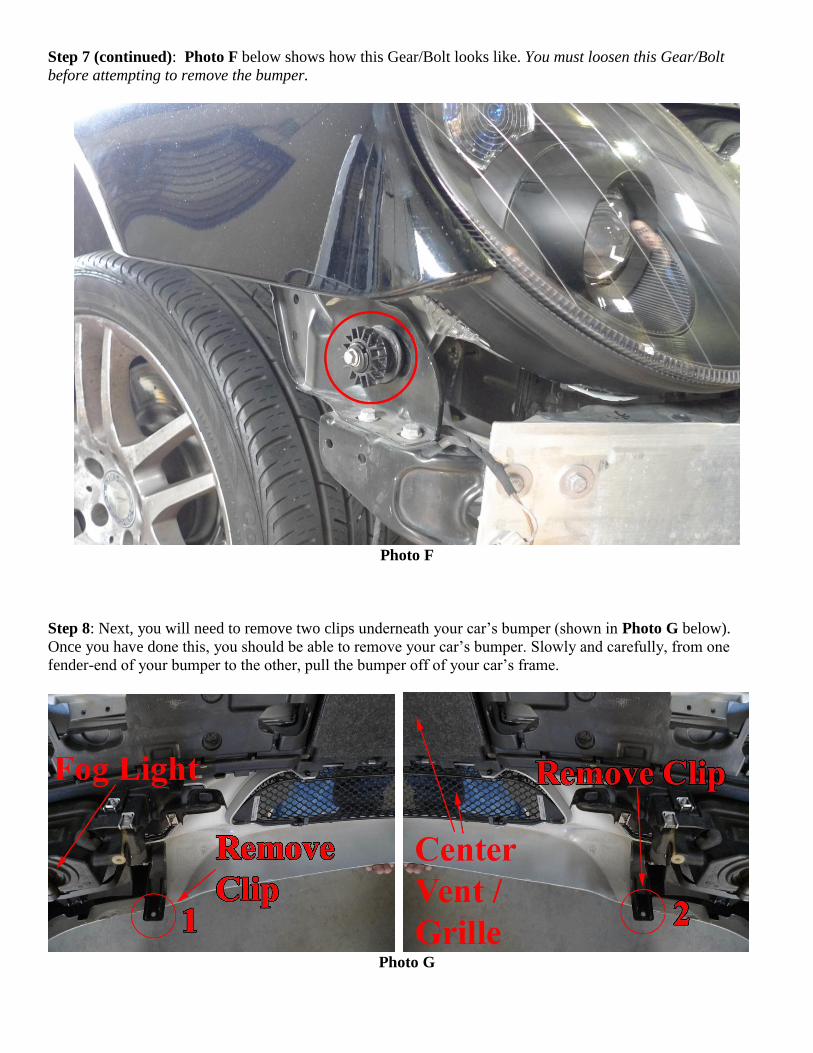
Step 7 (continued): Photo F below shows how this Gear/Bolt looks like. You must loosen this Gear/Bolt
before attempting to remove the bumper.
Photo F
Step 8: Next, you will need to remove two clips underneath your car’s bumper (shown in Photo G below).
Once you have done this, you should be able to remove your car’s bumper. Slowly and carefully, from one
fender-end of your bumper to the other, pull the bumper off of your car’s frame.
Photo G
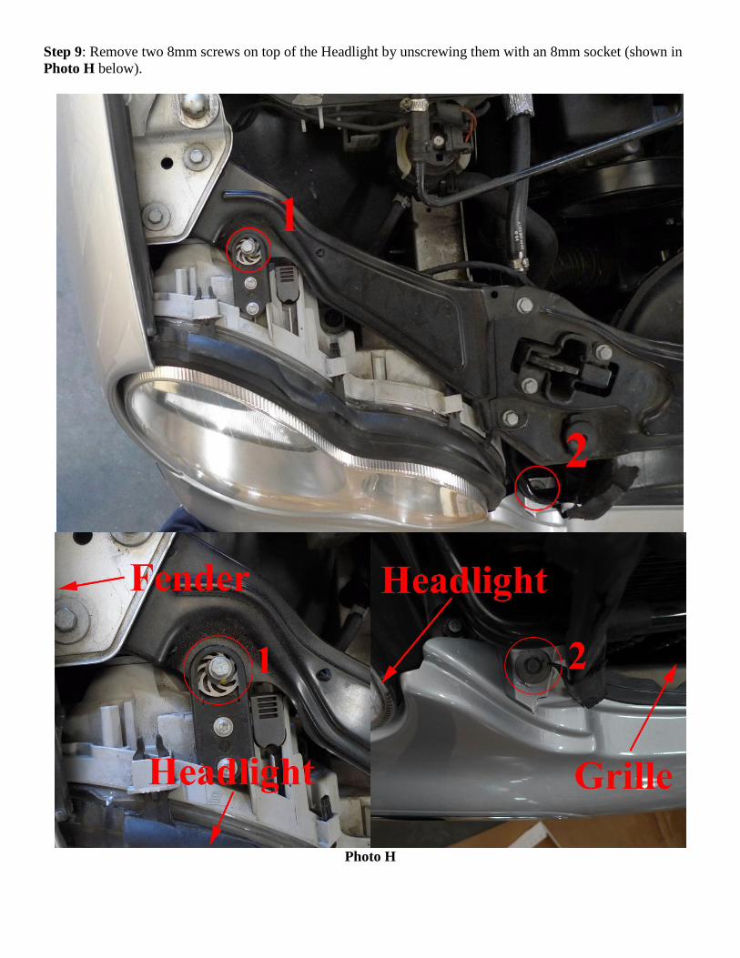
Step 9: Remove two 8mm screws on top of the Headlight by unscrewing them with an 8mm socket (shown in
Photo H below).
Photo H
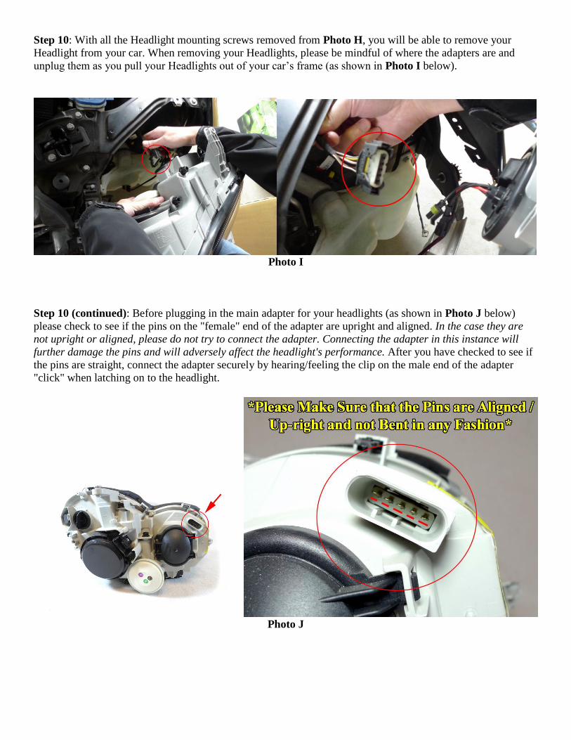
Step 10: With all the Headlight mounting screws removed from Photo H, you will be able to remove your
Headlight from your car. When removing your Headlights, please be mindful of where the adapters are and
unplug them as you pull your Headlights out of your car’s frame (as shown in Photo I below).
Photo I
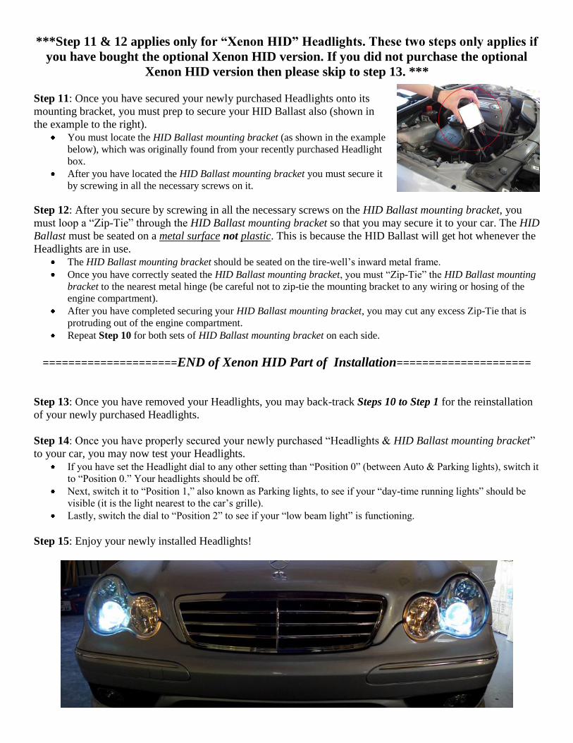
Step 10 (continued): Before plugging in the main adapter for your headlights (as shown in Photo J below)
please check to see if the pins on the "female" end of the adapter are upright and aligned. In the case they are
not upright or aligned, please do not try to connect the adapter. Connecting the adapter in this instance will
further damage the pins and will adversely affect the headlight's performance. After you have checked to see if
the pins are straight, connect the adapter securely by hearing/feeling the clip on the male end of the adapter
"click" when latching on to the headlight.
Photo J
***Step 11 & 12 applies only for “Xenon HID” Headlights. These two steps only applies if
you have bought the optional Xenon HID version. If you did not purchase the optional
Xenon HID version then please skip to step 13. ***
Step 11: Once you have secured your newly purchased Headlights onto its
mounting bracket, you must prep to secure your HID Ballast also (shown in
the example to the right).
You must locate the HID Ballast mounting bracket (as shown in the example
below), which was originally found from your recently purchased Headlight
box.
After you have located the HID Ballast mounting bracket you must secure it
by screwing in all the necessary screws on it.
Step 12: After you secure by screwing in all the necessary screws on the HID Ballast mounting bracket, you
must loop a “Zip-Tie” through the HID Ballast mounting bracket so that you may secure it to your car. The HID
Ballast must be seated on a metal surface not plastic. This is because the HID Ballast will get hot whenever the
Headlights are in use.
The HID Ballast mounting bracket should be seated on the tire-well’s inward metal frame.
Once you have correctly seated the HID Ballast mounting bracket, you must “Zip-Tie” the HID Ballast mounting
bracket to the nearest metal hinge (be careful not to zip-tie the mounting bracket to any wiring or hosing of the
engine compartment).
After you have completed securing your HID Ballast mounting bracket, you may cut any excess Zip-Tie that is
protruding out of the engine compartment.
Repeat Step 10 for both sets of HID Ballast mounting bracket on each side.
=====================END of Xenon HID Part of Installation=====================
Step 13: Once you have removed your Headlights, you may back-track Steps 10 to Step 1 for the reinstallation
of your newly purchased Headlights.
Step 14: Once you have properly secured your newly purchased “Headlights & HID Ballast mounting bracket”
to your car, you may now test your Headlights.
If you have set the Headlight dial to any other setting than “Position 0” (between Auto & Parking lights), switch it
to “Position 0.” Your headlights should be off.
Next, switch it to “Position 1,” also known as Parking lights, to see if your “day-time running lights” should be
visible (it is the light nearest to the car’s grille).
Lastly, switch the dial to “Position 2” to see if your “low beam light” is functioning.
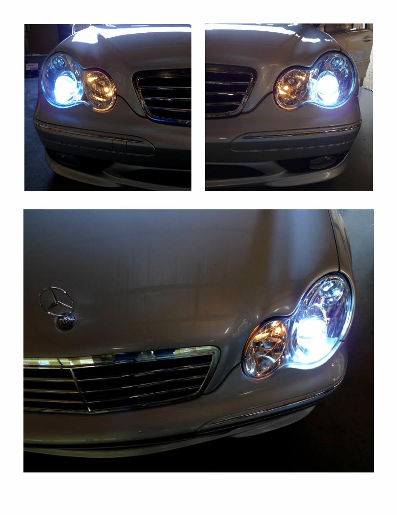
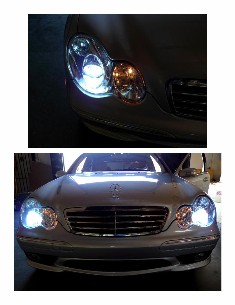
Step 15: Enjoy your newly installed Headlights!