HDMI Wireless Extender Installation Guide
12
1 Introduction The HDMI Wireless Extender provides an easy way to extend HDMI signals wirelessly up to 80 meters. Features and Benefits • Sends video and audio from your HDMI source to TV/display wirelessly in 1080p quality • Transmits content up to 80 meters LOS (Line of Sight) with no latency • Supports 2.4GHz frequency with channel hopping – channel automatically changes when an interference is detected with other RF sources • IR extender to control HDMI source device from the remote HDMI display end • Complete kit with a Transmitter (TX) and Receiver (RX) • HDMI output on Transmitter (TX) for a local TV/ display next to the source device • Wall mountable • LED status indicators for Power and Wireless connection System Requirements • PC or A/V devices with an available HDMI output port • HDMI display 04-0909A HDMI Wireless Extender Installation Guide
Transcript of HDMI Wireless Extender Installation Guide
1
IntroductionThe HDMI Wireless Extender provides an easy way toextend HDMI signals wirelessly up to 80 meters.
Features and Benefits• Sends video and audio from your HDMI source to
TV/display wirelessly in 1080p quality• Transmits content up to 80 meters LOS (Line of
Sight) with no latency• Supports 2.4GHz frequency with channel hopping
– channel automatically changes when aninterference is detected with other RF sources
• IR extender to control HDMI source device from theremote HDMI display end
• Complete kit with a Transmitter (TX) and Receiver(RX)
• HDMI output on Transmitter (TX) for a local TV/display next to the source device
• Wall mountable• LED status indicators for Power and Wireless
connection
System Requirements• PC or A/V devices with an available HDMI output port• HDMI display
04-0909A
HDMI Wireless ExtenderInstallation Guide
2
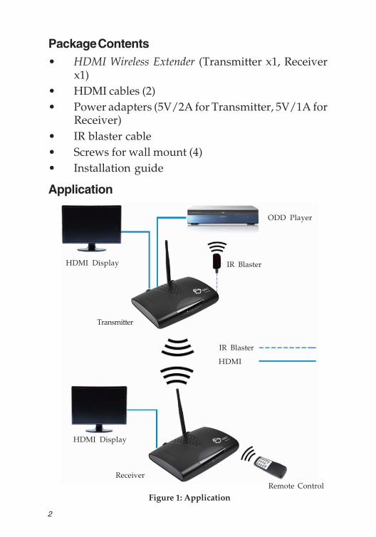
Package Contents• HDMI Wireless Extender (Transmitter x1, Receiver
x1)• HDMI cables (2)• Power adapters (5V/2A for Transmitter, 5V/1A for
Receiver)• IR blaster cable• Screws for wall mount (4)• Installation guide
Application
Figure 1: Application
HDMI Display
HDMI
ODD Player
HDMI Display
IR Blaster
IR Blaster
Receiver
Transmitter
Remote Control
3
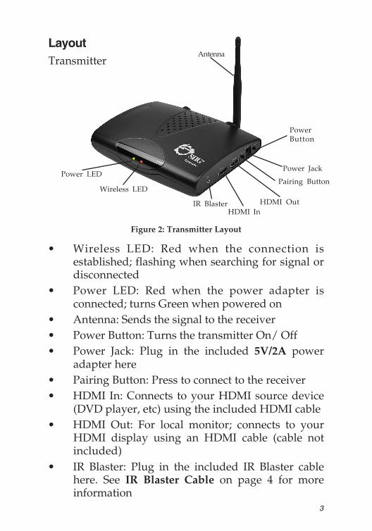
• Wireless LED: Red when the connection isestablished; flashing when searching for signal ordisconnected
• Power LED: Red when the power adapter isconnected; turns Green when powered on
• Antenna: Sends the signal to the receiver• Power Button: Turns the transmitter On/ Off• Power Jack: Plug in the included 5V/2A power
adapter here• Pairing Button: Press to connect to the receiver• HDMI In: Connects to your HDMI source device
(DVD player, etc) using the included HDMI cable• HDMI Out: For local monitor; connects to your
HDMI display using an HDMI cable (cable notincluded)
• IR Blaster: Plug in the included IR Blaster cablehere. See IR Blaster Cable on page 4 for moreinformation
LayoutTransmitter
PowerButton
Power LED
Wireless LEDPairing Button
HDMI In
Antenna
Power Jack
IR Blaster HDMI Out
Figure 2: Transmitter Layout
4
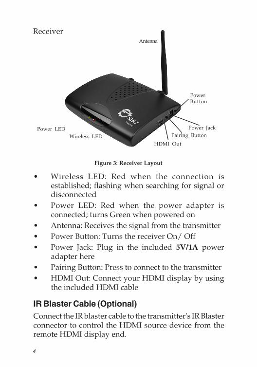
• Wireless LED: Red when the connection isestablished; flashing when searching for signal ordisconnected
• Power LED: Red when the power adapter isconnected; turns Green when powered on
• Antenna: Receives the signal from the transmitter• Power Button: Turns the receiver On/ Off• Power Jack: Plug in the included 5V/1A power
adapter here• Pairing Button: Press to connect to the transmitter• HDMI Out: Connect your HDMI display by using
the included HDMI cable
IR Blaster Cable (Optional)Connect the IR blaster cable to the transmitter's IR Blasterconnector to control the HDMI source device from theremote HDMI display end.
Figure 3: Receiver Layout
PowerButton
Power JackPower LEDWireless LED Pairing Button
Antenna
HDMI Out
Receiver
5
Outsidediameter(OD)
Insidediameter(ID)
Pluglength(L)
Negative / Positive
5.3(mm) 2.2(mm) 11.5(mm)*Center pin for positive voltage and theouter shield for negative voltage
OD ID
L
DC Power JackRefer to the table below for the specifications of thepower adapter.
Table 1: Power Adapter Specifications
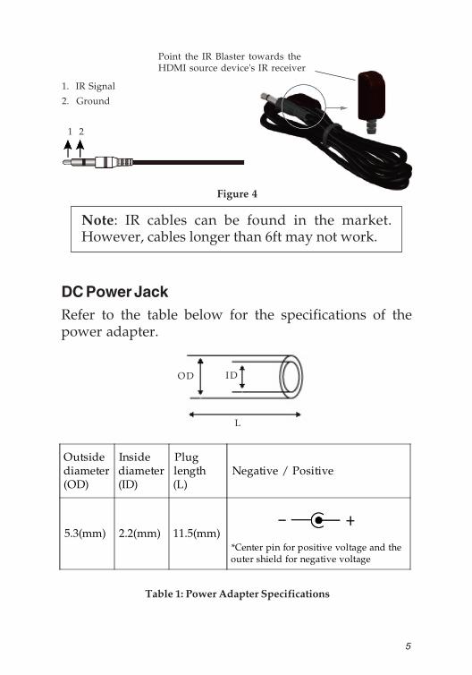
1. IR Signal
2. Ground
Figure 4
1 2
Note: IR cables can be found in the market.However, cables longer than 6ft may not work.
Point the IR Blaster towards theHDMI source device's IR receiver
6
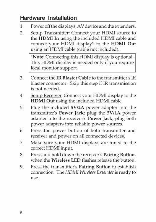
Hardware Installation1. Power off the displays, AV device and the extenders.2. Setup Transmitter: Connect your HDMI source to
the HDMI In using the included HDMI cable andconnect your HDMI display* to the HDMI Outusing an HDMI cable (cable not included).
*Note: Connecting this HDMI display is optional.This HDMI display is needed only if you requirelocal monitor support.
3. Connect the IR Blaster Cable to the transmitter's IRblaster connector. Skip this step if IR transmissionis not needed.
4. Setup Receiver: Connect your HDMI display to theHDMI Out using the included HDMI cable.
5. Plug the included 5V/2A power adapter into thetransmitter's Power Jack; plug the 5V/1A poweradapter into the receiver's Power Jack; plug bothpower adapters into reliable power sources.
6. Press the power button of both transmitter andreceiver and power on all connected devices.
7. Make sure your HDMI displays are tuned to thecorrect HDMI input.
8. Press and hold down the receiver's Pairing Button,when the Wireless LED flashes release the button.
9. Press the transmitter's Pairing Button to establishconnection. The HDMI Wireless Extender is ready touse.
7
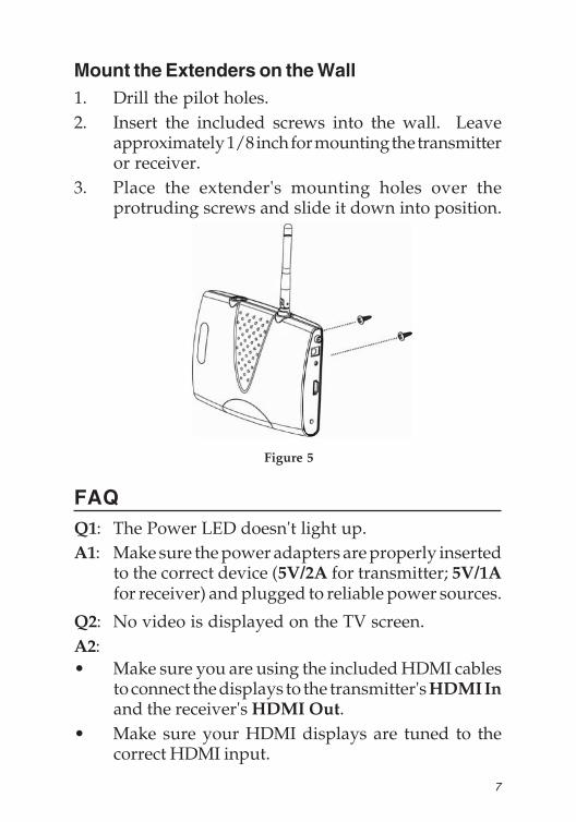
Figure 5
Mount the Extenders on the Wall1. Drill the pilot holes.2. Insert the included screws into the wall. Leave
approximately 1/8 inch for mounting the transmitteror receiver.
3. Place the extender's mounting holes over theprotruding screws and slide it down into position.
FAQQ1: The Power LED doesn't light up.A1: Make sure the power adapters are properly inserted
to the correct device (5V/2A for transmitter; 5V/1Afor receiver) and plugged to reliable power sources.
Q2: No video is displayed on the TV screen.A2:• Make sure you are using the included HDMI cables
to connect the displays to the transmitter's HDMI Inand the receiver's HDMI Out.
• Make sure your HDMI displays are tuned to thecorrect HDMI input.
8
• Verify the Power LEDs and Wireless LEDs:If the wireless LEDs are flashing red:Move the transmitter closer to the receiver. Thetransmission range between the transmitter and thereceiver should not exceed 80 meters (LOS-line ofsight) transmission distance.If the wireless LEDs are off:
• Make sure your HDMI displays, HDMI sourcedevice and the wireless extenders are powered on.
• Make sure you are using the included HDMI cablesto connect your HDMI source device to thetransmitter's HDMI In and your HDMI display tothe receiver's HDMI Out.
Q3: No audio.A3:• Make sure the volume it turned up and not in
"Mute" mode.• Make sure the audio bit rate from the HDMI source
device can be supported by the transmitter andreceiver.
Q4: IR Blaster can't control source device.A4: Make sure the transmitter is powered on and the IR
Blaster is placed close to and pointed directly at theHDMI source device's IR receiver.

9
Blank Page

10
Blank Page
11
Technical Support and WarrantyQUESTIONS? SIIG’s Online Support has answers! Simply visit our web siteat www.siig.com and click Support. Our online support database is updateddaily with new drivers and solutions. Answers to your questions could bejust a few clicks away. You can also submit questions online and a technicalsupport analyst will promptly respond.SIIG offers a 2-year manufacturer warranty with this product. This warrantycovers the original purchaser and guarantees the product to be free of anydefects in materials or workmanship for two (2) years from the date ofpurchase of the product.SIIG will, at our discretion, repair or replace (with an identical product orproduct having similar features and functionality) the product if defective inmaterials or workmanship. This warranty gives you specific legal rights, andyou may also have other rights which vary from state to state. Please see ourweb site for more warranty details.If you encounter any problems with this product, please follow the proceduresbelow.A) If it is within the store's return policy period, please return the productto the store where you purchased it.B) If your purchase has passed the store's return policy period, please followthese steps to have the product repaired or replaced.
Step 1: Submit your RMA request. Go to www.siig.com, click Support,then Request A Product Replacement to submit a request to SIIG RMAor fax a request to 510-657-5962. Your RMA request will be processed,if the product is determined to be defective, an RMA number will beissued.Step 2: After obtaining an RMA number, ship the product.• Properly pack the product for shipping. All software, cable(s) and any
other accessories that came with the original package must be included.• Clearly write your RMA number on the top of the returned package.
SIIG will refuse to accept any shipping package, and will not beresponsible for a product returned without an RMA number postedon the outside of the shipping carton.
• You are responsible for the cost of shipping to SIIG. Ship the productto the following address:SIIG, Inc.6078 Stewart AvenueFremont, CA 94538-3152, USARMA #:
• SIIG will ship the repaired or replaced product via Ground in the U.S.and International Economy outside of the U.S. at no cost to thecustomer.

About SIIG, Inc.Founded in 1985, SIIG, Inc. is a leading manufacturer of IT connectivitysolutions (including Serial ATA and Ultra ATA Controllers, FireWire, USB,and legacy I/O adapters) that bridge the connection between Desktop/Notebook systems and external peripherals. SIIG continues to grow byadding A/V and Digital Signage connectivity solutions to our extensiveportfolio. All centered around the distribution and switching of A/V signalsover CAT5/6, these products include matrix switches, distribution amplifiers,extenders, converters, splitters, cabling, and more.SIIG is the premier one-stop source of upgrades and is committed toproviding high quality products while keeping economical and competitiveprices. High-quality control standards are evident by one of the lowestdefective return rates in the industry. Our products offer comprehensiveuser manuals, user-friendly features, and most products are backed by alifetime warranty.SIIG products can be found in many computer retail stores, mail ordercatalogs, and e-commerce sites in the Americas, as well as through majordistributors, system integrators, and VARs.
HDMI Wireless Extender is a trademark of SIIG, Inc. SIIG and the SIIG logo are registered trademarksof SIIG, Inc. Microsoft and Windows are registered trademarks of Microsoft Corporation. All othernames used in this publication are for identification only and may be trademarks of their respectiveowners.
October, 2013 Copyright © 2013 by SIIG, Inc. All rights reserved.
PRODUCT NAMEHDMI Wireless Extender
FCC RULES: TESTED TO COMPLY WITH FCC PART 15, CLASSB OPERATING ENVIRONMENT: FOR HOME OR OFFICE USE
FCC COMPLIANCE STATEMENT:This device complies with part 15 of the FCC Rules. Operation issubject to the following two conditions: (1) This device may not causeharmful interference, and (2) this device must accept any interferencereceived, including interference that may cause undesired operation.
THE PARTY RESPONSIBLE FOR PRODUCT COMPLIANCE
SIIG, Inc.6078 Stewart AvenueFremont, CA 94538-3152, USAPhone: 510-657-8688