HDL Example 4-10 //------------------------------------------ //Gate-level description of circuit of...
48
-
Upload
danny-bruton -
Category
Documents
-
view
213 -
download
0
Transcript of HDL Example 4-10 //------------------------------------------ //Gate-level description of circuit of...
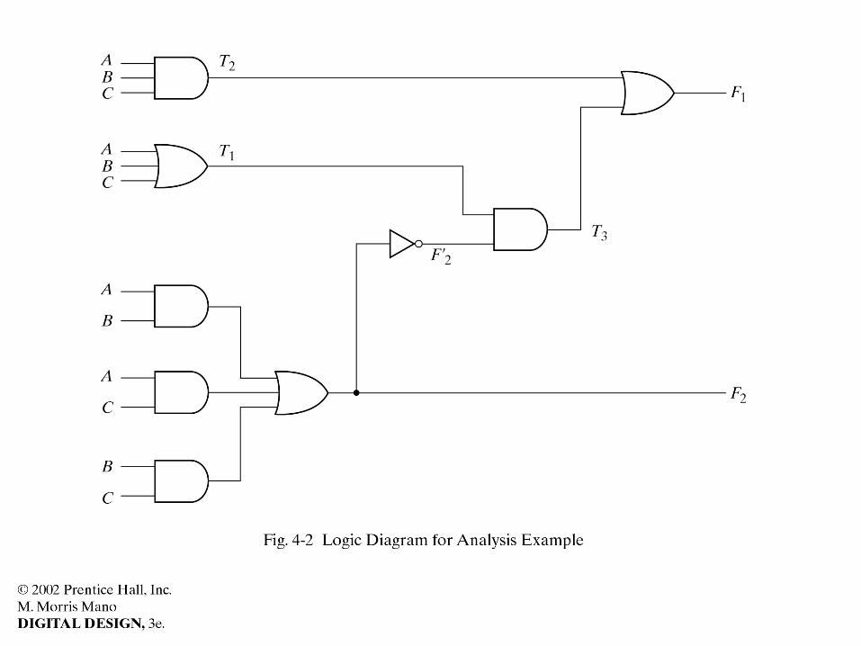
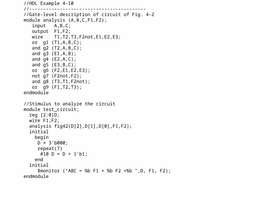
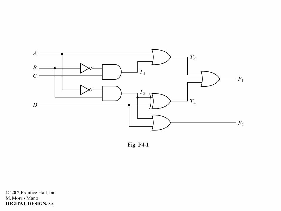
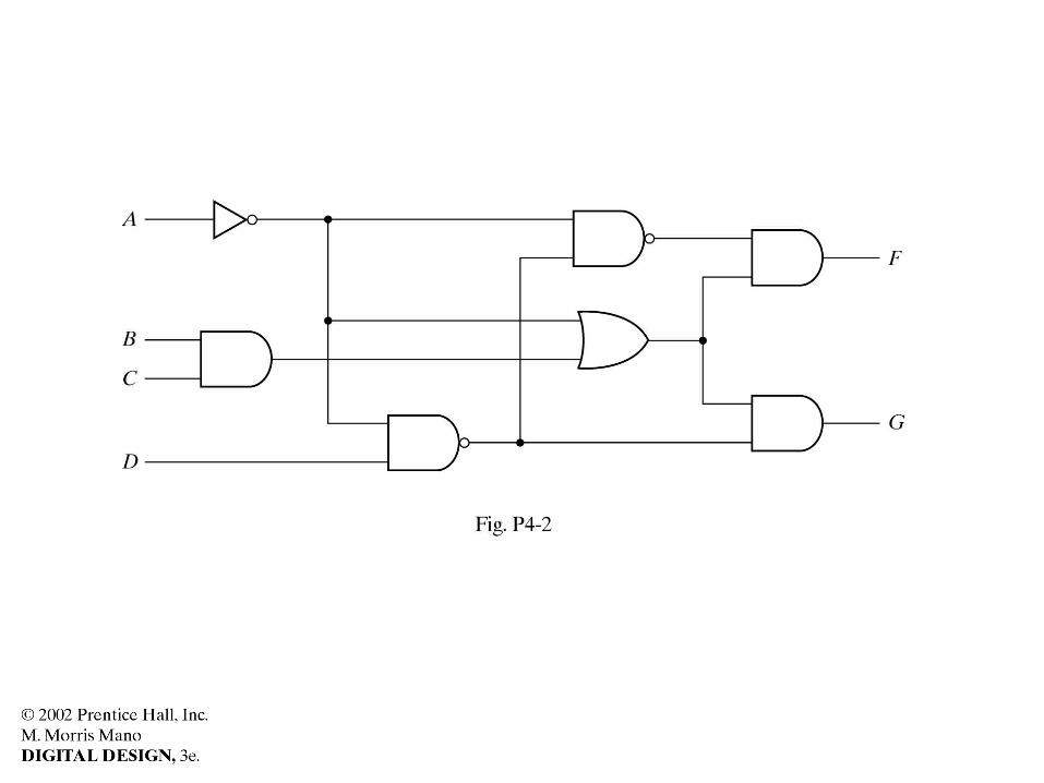
//HDL Example 4-10//------------------------------------------ //Gate-level description of circuit of Fig. 4-2 module analysis (A,B,C,F1,F2); input A,B,C; output F1,F2; wire T1,T2,T3,F2not,E1,E2,E3; or g1 (T1,A,B,C); and g2 (T2,A,B,C); and g3 (E1,A,B); and g4 (E2,A,C); and g5 (E3,B,C); or g6 (F2,E1,E2,E3); not g7 (F2not,F2); and g8 (T3,T1,F2not); or g9 (F1,T2,T3);endmodule
//Stimulus to analyze the circuitmodule test_circuit; reg [2:0]D; wire F1,F2; analysis fig42(D[2],D[1],D[0],F1,F2); initial begin D = 3'b000; repeat(7) #10 D = D + 1'b1; end initial $monitor ("ABC = %b F1 = %b F2 =%b ",D, F1, F2);endmodule
//HDL Example 4-2//----------------------------------------------- //Gate-level hierarchical description of 4-bit
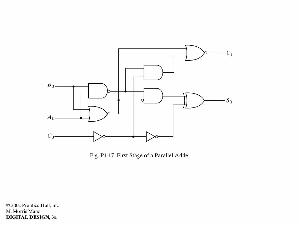
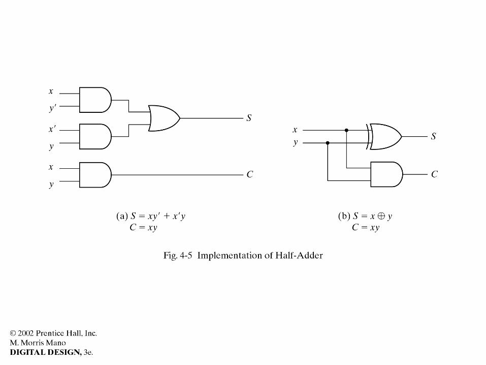
adder // Description of half adder (see Fig 4-5b)module halfadder (S,C,x,y); input x,y; output S,C;//Instantiate primitive gates xor (S,x,y); and (C,x,y);endmodule
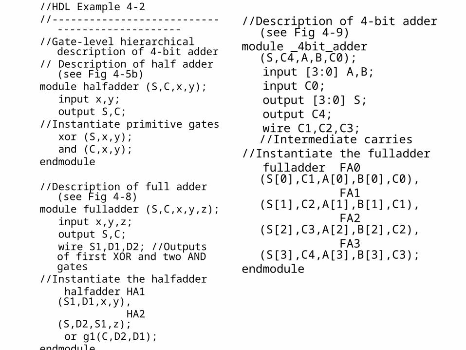
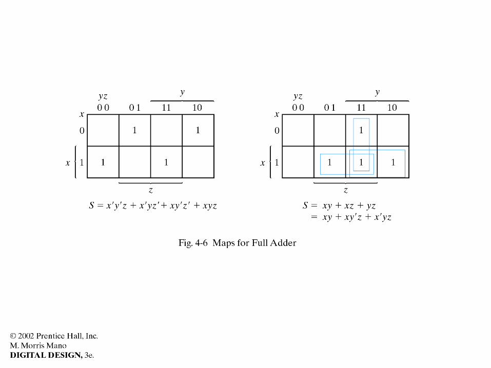
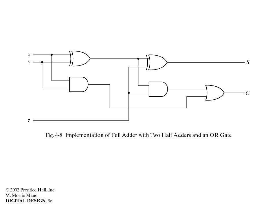
//Description of full adder (see Fig 4-8)module fulladder (S,C,x,y,z); input x,y,z; output S,C; wire S1,D1,D2; //Outputs of first XOR
and two AND gates //Instantiate the halfadder halfadder HA1 (S1,D1,x,y), HA2 (S,D2,S1,z); or g1(C,D2,D1);endmodule
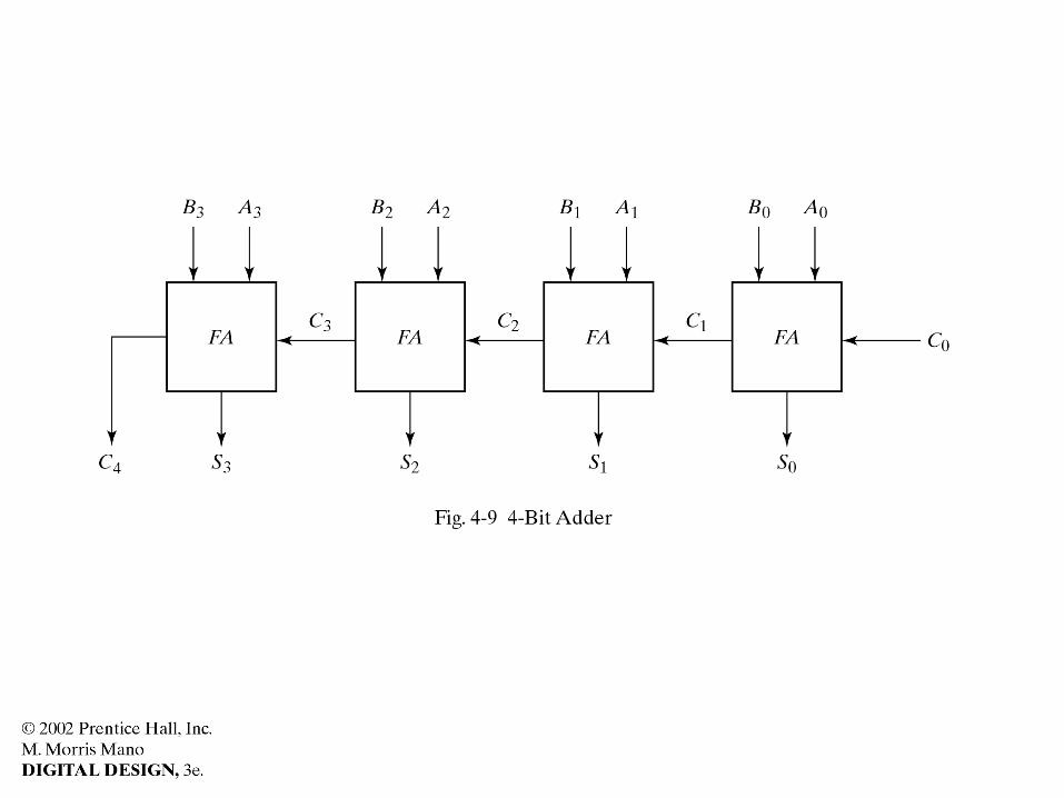
//Description of 4-bit adder (see Fig 4-9)module _4bit_adder (S,C4,A,B,C0); input [3:0] A,B; input C0; output [3:0] S; output C4; wire C1,C2,C3; //Intermediate carries//Instantiate the fulladder fulladder FA0 (S[0],C1,A[0],B[0],C0), FA1 (S[1],C2,A[1],B[1],C1), FA2 (S[2],C3,A[2],B[2],C2), FA3 (S[3],C4,A[3],B[3],C3);endmodule

//HDL Example 4-2//----------------------------------------------- //Gate-level hierarchical description of 4-bit adder // Description of half adder (see Fig 4-5b)module halfadder (S,C,x,y); input x,y; output S,C;//Instantiate primitive gates xor (S,x,y); and (C,x,y);endmodule
//Description of full adder (see Fig 4-8)module fulladder (S,C,x,y,z); input x,y,z; output S,C; wire S1,D1,D2; //Outputs of first XOR and two AND gates //Instantiate the halfadder halfadder HA1 (S1,D1,x,y), HA2 (S,D2,S1,z); or g1(C,D2,D1);endmodule
//Description of 4-bit adder (see Fig 4-9)module _4bit_adder (S,C4,A,B,C0); input [3:0] A,B; input C0; output [3:0] S; output C4; wire C1,C2,C3; //Intermediate carries//Instantiate the fulladder fulladder FA0 (S[0],C1,A[0],B[0],C0), FA1 (S[1],C2,A[1],B[1],C1), FA2 (S[2],C3,A[2],B[2],C2), FA3 (S[3],C4,A[3],B[3],C3);endmodule
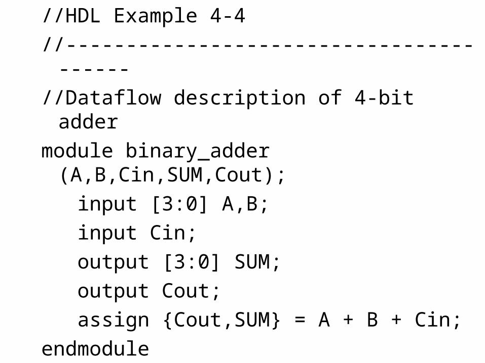
//HDL Example 4-4
//----------------------------------------
//Dataflow description of 4-bit adder
module binary_adder (A,B,Cin,SUM,Cout);
input [3:0] A,B;
input Cin;
output [3:0] SUM;
output Cout;
assign {Cout,SUM} = A + B + Cin;
endmodule

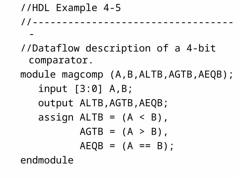
//HDL Example 4-5
//-----------------------------------
//Dataflow description of a 4-bit comparator.
module magcomp (A,B,ALTB,AGTB,AEQB);
input [3:0] A,B;
output ALTB,AGTB,AEQB;
assign ALTB = (A < B),
AGTB = (A > B),
AEQB = (A == B);
endmodule

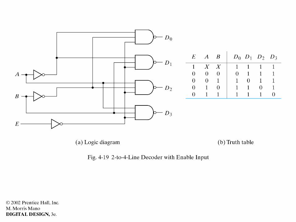
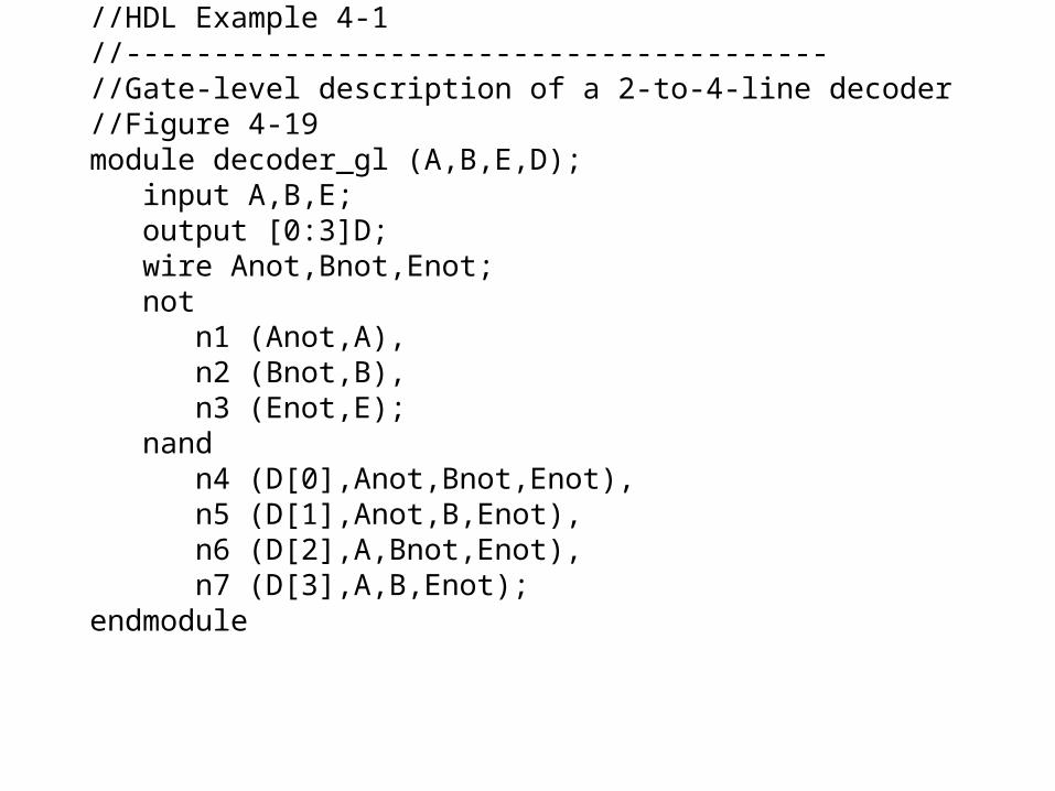
//HDL Example 4-1//---------------------------------------- //Gate-level description of a 2-to-4-line decoder//Figure 4-19 module decoder_gl (A,B,E,D); input A,B,E; output [0:3]D; wire Anot,Bnot,Enot; not n1 (Anot,A), n2 (Bnot,B), n3 (Enot,E); nand n4 (D[0],Anot,Bnot,Enot), n5 (D[1],Anot,B,Enot), n6 (D[2],A,Bnot,Enot), n7 (D[3],A,B,Enot);endmodule
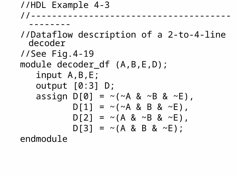
//HDL Example 4-3//---------------------------------------------- //Dataflow description of a 2-to-4-line decoder //See Fig.4-19module decoder_df (A,B,E,D); input A,B,E; output [0:3] D; assign D[0] = ~(~A & ~B & ~E), D[1] = ~(~A & B & ~E), D[2] = ~(A & ~B & ~E), D[3] = ~(A & B & ~E);endmodule

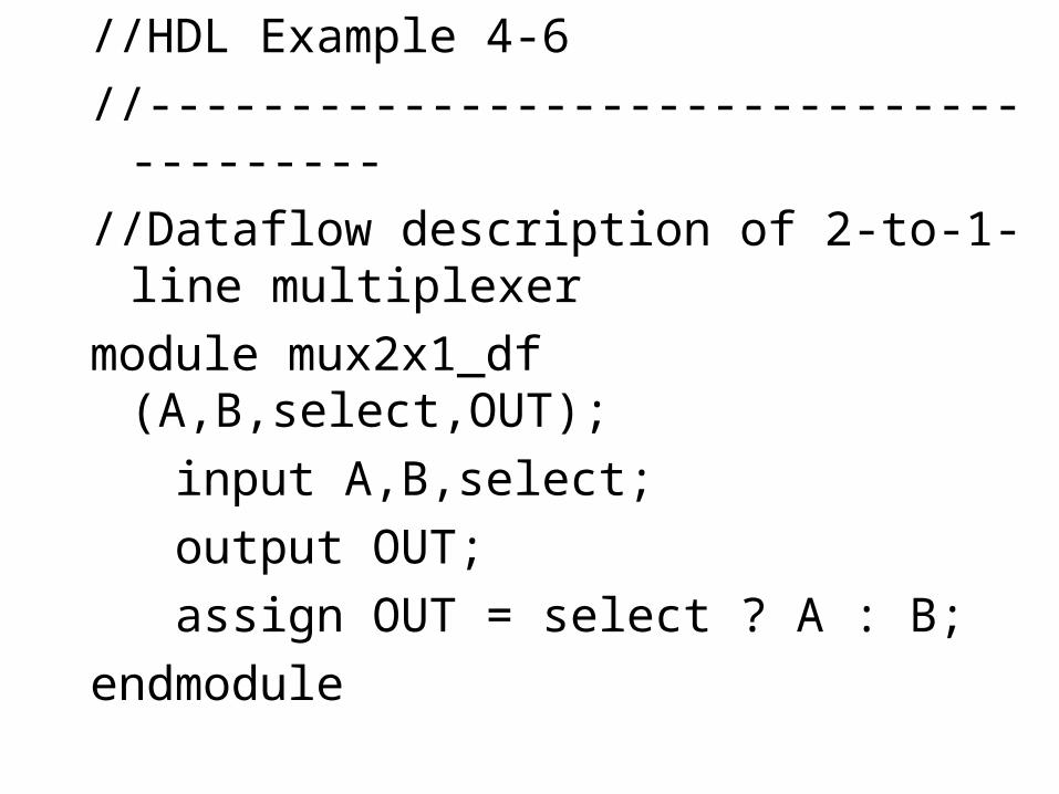
//HDL Example 4-6
//----------------------------------------
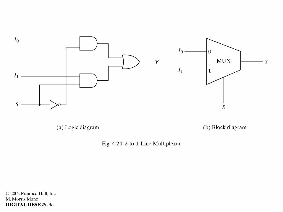
//Dataflow description of 2-to-1-line multiplexer
module mux2x1_df (A,B,select,OUT);
input A,B,select;
output OUT;
assign OUT = select ? A : B;
endmodule
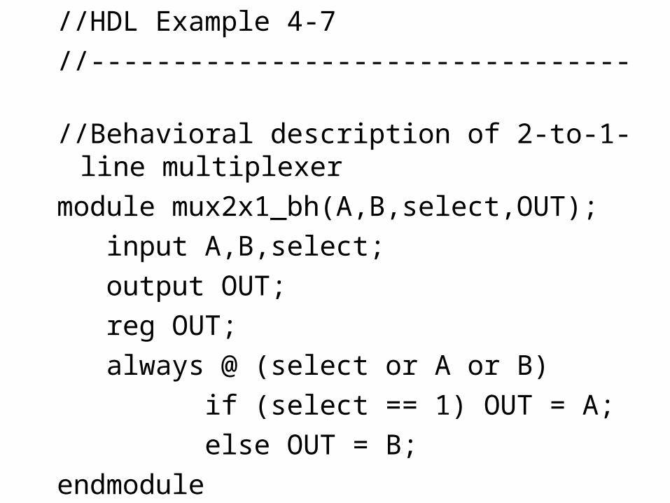
//HDL Example 4-7
//---------------------------------
//Behavioral description of 2-to-1-line multiplexer
module mux2x1_bh(A,B,select,OUT);
input A,B,select;
output OUT;
reg OUT;
always @ (select or A or B)
if (select == 1) OUT = A;
else OUT = B;
endmodule
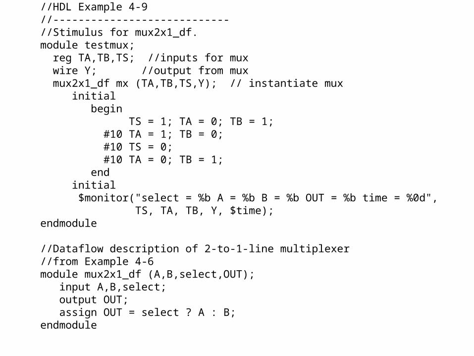
//HDL Example 4-9//---------------------------- //Stimulus for mux2x1_df.module testmux; reg TA,TB,TS; //inputs for mux wire Y; //output from mux mux2x1_df mx (TA,TB,TS,Y); // instantiate mux initial begin TS = 1; TA = 0; TB = 1; #10 TA = 1; TB = 0; #10 TS = 0; #10 TA = 0; TB = 1; end initial $monitor("select = %b A = %b B = %b OUT = %b time = %0d", TS, TA, TB, Y, $time);endmodule //Dataflow description of 2-to-1-line multiplexer//from Example 4-6module mux2x1_df (A,B,select,OUT); input A,B,select; output OUT; assign OUT = select ? A : B;endmodule
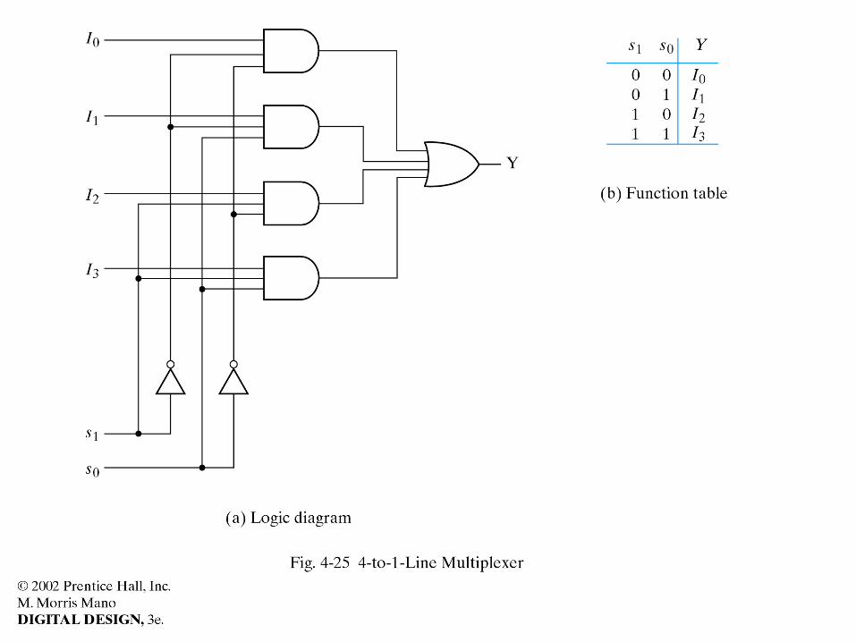
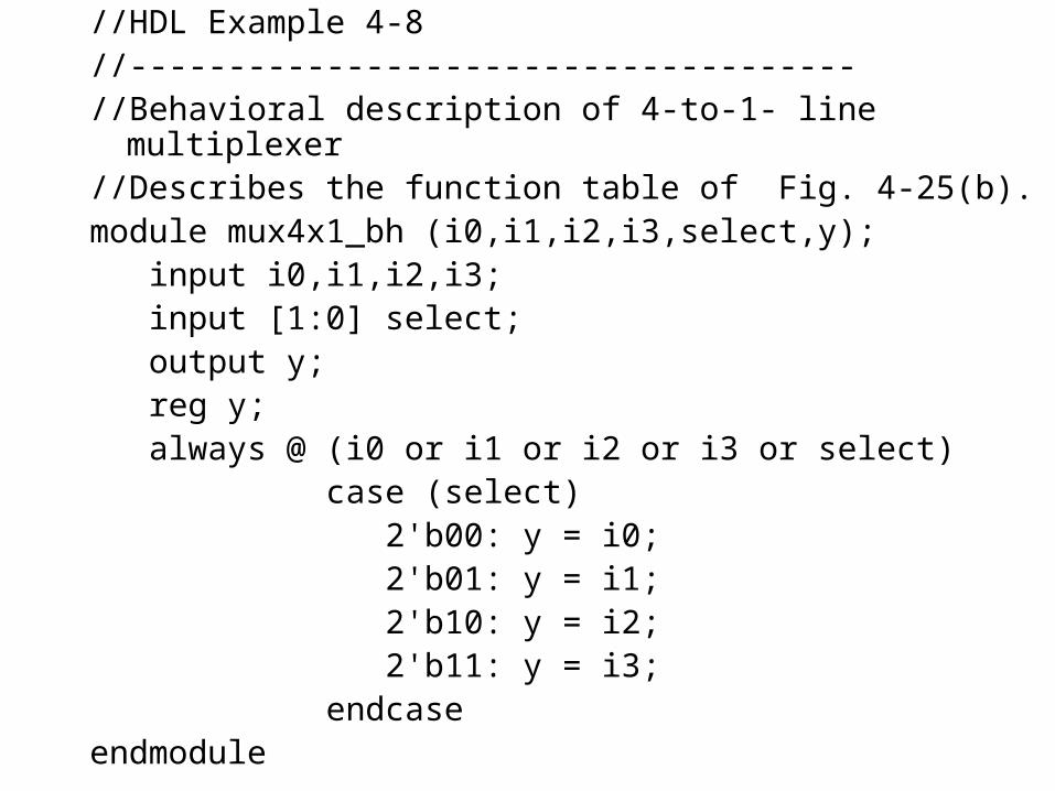
//HDL Example 4-8//------------------------------------- //Behavioral description of 4-to-1- line multiplexer//Describes the function table of Fig. 4-25(b).module mux4x1_bh (i0,i1,i2,i3,select,y); input i0,i1,i2,i3; input [1:0] select; output y; reg y; always @ (i0 or i1 or i2 or i3 or select) case (select) 2'b00: y = i0; 2'b01: y = i1; 2'b10: y = i2; 2'b11: y = i3; endcaseendmodule