HDA design anchor - Hilti anchor design software Nuclear A4 316 ... HDA design anchor Setting ... TE...
5
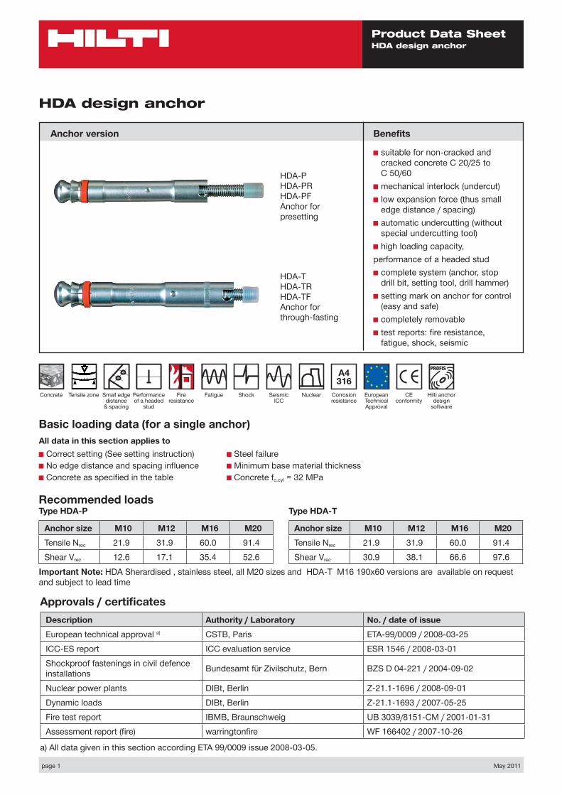
page 1 May 2011 Product Data Sheet HDA design anchor Basic loading data (for a single anchor) All data in this section applies to ■ Correct setting (See setting instruction) ■ No edge distance and spacing influence ■ Concrete as specified in the table ■ Steel failure ■ Minimum base material thickness ■ Concrete f c,cyl = 32 MPa HDA design anchor Anchor version CE conformity European Technical Approval Fire resistance Concrete Tensile zone Shock Fatigue Seismic ICC Benefits ■ suitable for non-cracked and cracked concrete C 20/25 to C 50/60 ■ mechanical interlock (undercut) ■ low expansion force (thus small edge distance / spacing) ■ automatic undercutting (without special undercutting tool) ■ high loading capacity, performance of a headed stud ■ complete system (anchor, stop drill bit, setting tool, drill hammer) ■ setting mark on anchor for control (easy and safe) ■ completely removable ■ test reports: fire resistance, fatigue, shock, seismic HDA-P HDA-PR HDA-PF Anchor for presetting HDA-T HDA-TR HDA-TF Anchor for through-fasting Hilti anchor design software Nuclear A4 316 Corrosion resistance Small edge distance & spacing Performance of a headed stud Approvals / certificates Description Authority / Laboratory No. / date of issue European technical approval a) CSTB, Paris ETA-99/0009 / 2008-03-25 ICC-ES report ICC evaluation service ESR 1546 / 2008-03-01 Shockproof fastenings in civil defence installations Bundesamt für Zivilschutz, Bern BZS D 04-221 / 2004-09-02 Nuclear power plants DIBt, Berlin Z-21.1-1696 / 2008-09-01 Dynamic loads DIBt, Berlin Z-21.1-1693 / 2007-05-25 Fire test report IBMB, Braunschweig UB 3039/8151-CM / 2001-01-31 Assessment report (fire) warringtonfire WF 166402 / 2007-10-26 a) All data given in this section according ETA 99/0009 issue 2008-03-05. Recommended loads Type HDA-P Anchor size M10 M12 M16 M20 Tensile N rec 21.9 31.9 60.0 91.4 Shear V rec 12.6 17.1 35.4 52.6 Important Note: HDA Sherardised , stainless steel, all M20 sizes and HDA-T M16 190x60 versions are available on request and subject to lead time Type HDA-T Anchor size M10 M12 M16 M20 Tensile N rec 21.9 31.9 60.0 91.4 Shear V rec 30.9 38.1 66.6 97.6
Transcript of HDA design anchor - Hilti anchor design software Nuclear A4 316 ... HDA design anchor Setting ... TE...
page 1 May 2011
Product Data SheetHDA design anchor
Basic loading data (for a single anchor)All data in this section applies to■ Correct setting (See setting instruction)■ No edge distance and spacing influence■ Concrete as specified in the table
■ Steel failure■ Minimum base material thickness ■ Concrete fc,cyl = 32 MPa
HDA design anchor
Anchor version
CE conformity
European Technical Approval
Fire resistance
Concrete Tensile zone ShockFatigue Seismic ICC
Benefits
■ suitable for non-cracked and cracked concrete C 20/25 to C 50/60
■ mechanical interlock (undercut)■ low expansion force (thus small
edge distance / spacing)■ automatic undercutting (without
special undercutting tool)■ high loading capacity,performance of a headed stud■ complete system (anchor, stop
drill bit, setting tool, drill hammer)■ setting mark on anchor for control
(easy and safe)■ completely removable■ test reports: fire resistance,
fatigue, shock, seismic
HDA-PHDA-PRHDA-PFAnchor for presetting
HDA-THDA-TRHDA-TFAnchor for through-fasting
Hilti anchor design
software
Nuclear
A4 316
Corrosion resistance
Small edge distance
& spacing
Performance of a headed
stud
Approvals / certificatesDescription Authority / Laboratory No. / date of issueEuropean technical approval a) CSTB, Paris ETA-99/0009 / 2008-03-25ICC-ES report ICC evaluation service ESR 1546 / 2008-03-01Shockproof fastenings in civil defence installations Bundesamt für Zivilschutz, Bern BZS D 04-221 / 2004-09-02
Nuclear power plants DIBt, Berlin Z-21.1-1696 / 2008-09-01Dynamic loads DIBt, Berlin Z-21.1-1693 / 2007-05-25Fire test report IBMB, Braunschweig UB 3039/8151-CM / 2001-01-31Assessment report (fire) warringtonfire WF 166402 / 2007-10-26
a) All data given in this section according ETA 99/0009 issue 2008-03-05.
Recommended loadsType HDA-P
Anchor size M10 M12 M16 M20Tensile Nrec 21.9 31.9 60.0 91.4Shear Vrec 12.6 17.1 35.4 52.6
Important Note: HDA Sherardised , stainless steel, all M20 sizes and HDA-T M16 190x60 versions are available on request and subject to lead time
Type HDA-T
Anchor size M10 M12 M16 M20Tensile Nrec 21.9 31.9 60.0 91.4Shear Vrec 30.9 38.1 66.6 97.6
page 2 May 2011
Product Data SheetHDA design anchor
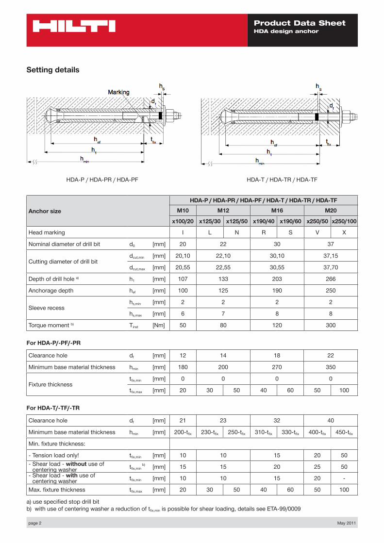
Setting details
Anchor size
HDA-P / HDA-PR / HDA-PF / HDA-T / HDA-TR / HDA-TF
M10 M12 M16 M20
x100/20 x125/30 x125/50 x190/40 x190/60 x250/50 x250/100
Head marking I L N R S V X
Nominal diameter of drill bit d0 [mm] 20 22 30 37
Cutting diameter of drill bitdcut,min [mm] 20,10 22,10 30,10 37,15
dcut,max [mm] 20,55 22,55 30,55 37,70
Depth of drill hole a) h1 [mm] 107 133 203 266
Anchorage depth hef [mm] 100 125 190 250
Sleeve recesshs,min [mm] 2 2 2 2
hs,max [mm] 6 7 8 8
Torque moment b) Tinst [Nm] 50 80 120 300
For HDA-P/-PF/-PR
Clearance hole df [mm] 12 14 18 22
Minimum base material thickness hmin [mm] 180 200 270 350
Fixture thicknesstfix,min [mm] 0 0 0 0
tfix,max [mm] 20 30 50 40 60 50 100
For HDA-T/-TF/-TR
Clearance hole df [mm] 21 23 32 40
Minimum base material thickness hmin [mm] 200-tfix 230-tfix 250-tfix 310-tfix 330-tfix 400-tfix 450-tfix
Min. fixture thickness:
- Tension load only! tfix,min [mm] 10 10 15 20 50- Shear load - without use of
centering washer tfix,min b) [mm] 15 15 20 25 50
- Shear load - with use of centering washer tfix,min [mm] 10 10 15 20 -
Max. fixture thickness tfix,max [mm] 20 30 50 40 60 50 100
a) use specified stop drill bitb) with use of centering washer a reduction of tfix,min is possible for shear loading, details see ETA-99/0009
HDA-P / HDA-PR / HDA-PF HDA-T / HDA-TR / HDA-TF
page 3 May 2011
Product Data SheetHDA design anchor
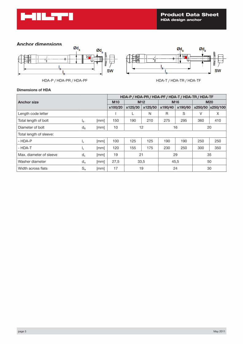
Dimensions of HDA
Anchor sizeHDA-P / HDA-PR / HDA-PF / HDA-T / HDA-TR / HDA-TF
M10 M12 M16 M20x100/20 x125/30 x125/50 x190/40 x190/60 x250/50 x250/100
Length code letter I L N R S V X
Total length of bolt lB [mm] 150 190 210 275 295 360 410
Diameter of bolt dB [mm] 10 12 16 20
Total length of sleeve:
- HDA-P ls [mm] 100 125 125 190 190 250 250
- HDA-T ls [mm] 120 155 175 230 250 300 350
Max. diameter of sleeve ds [mm] 19 21 29 35
Washer diameter dw [mm] 27,5 33,5 45,5 50
Width across flats Sw [mm] 17 19 24 30
Anchor dimensions
HDA-P / HDA-PR / HDA-PF HDA-T / HDA-TR / HDA-TF
page 4 May 2011
Product Data SheetHDA design anchor
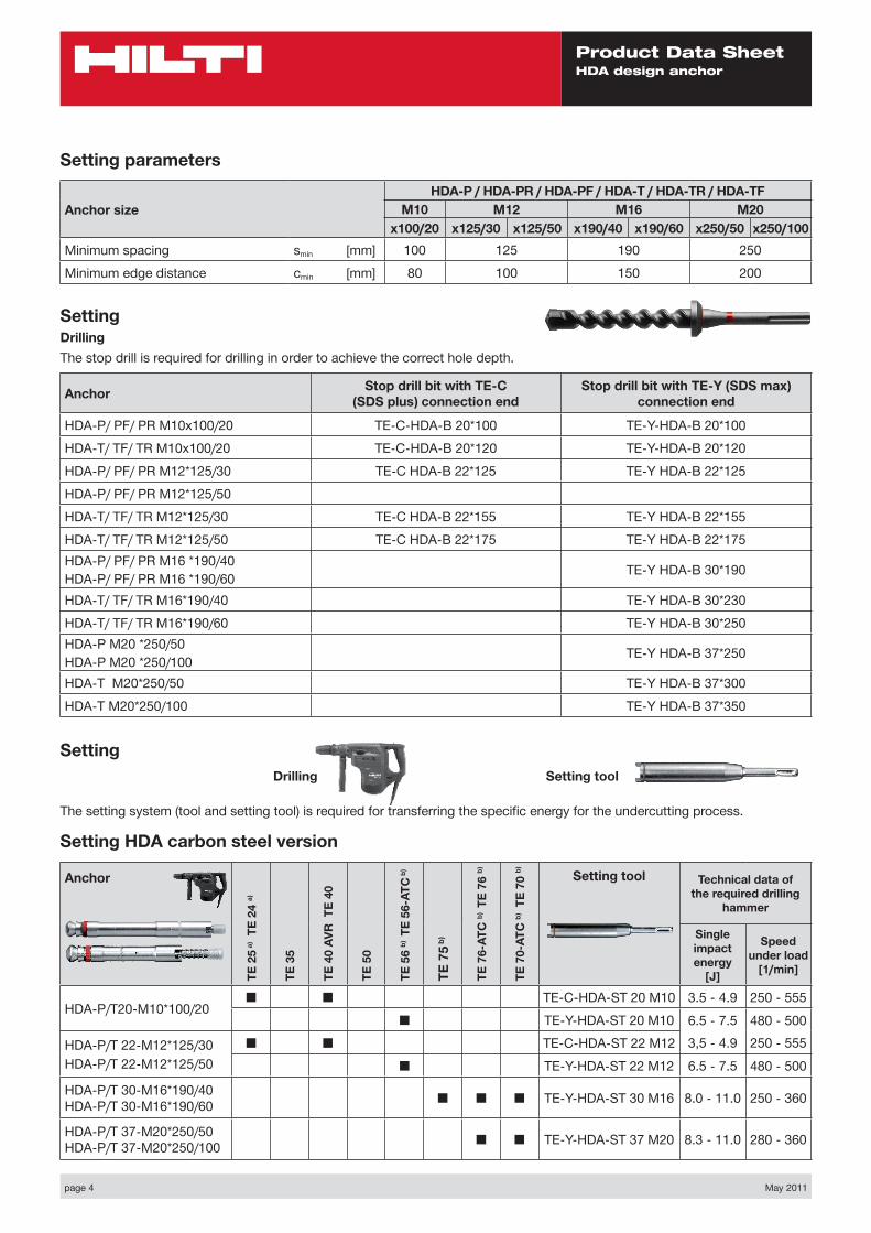
Setting
The setting system (tool and setting tool) is required for transferring the specific energy for the undercutting process.
Drilling Setting tool
Setting HDA carbon steel version
Anchor
TE 2
5 a)
TE 2
4 a)
TE 3
5
TE 4
0 AV
R T
E 40
TE 5
0
TE 5
6 b)
TE
56-A
TC b
)
TE 7
5 b)
TE 7
6-AT
C b)
TE
76 b)
TE 7
0-AT
C b)
TE
70 b) Setting tool Technical data of
the required drilling hammer
Single impact energy
[J]
Speed under load
[1/min]
HDA-P/T20-M10*100/20■ ■ TE-C-HDA-ST 20 M10 3.5 - 4.9 250 - 555
■ TE-Y-HDA-ST 20 M10 6.5 - 7.5 480 - 500
HDA-P/T 22-M12*125/30 HDA-P/T 22-M12*125/50
■ ■ TE-C-HDA-ST 22 M12 3,5 - 4.9 250 - 555
■ TE-Y-HDA-ST 22 M12 6.5 - 7.5 480 - 500
HDA-P/T 30-M16*190/40 HDA-P/T 30-M16*190/60 ■ ■ ■ TE-Y-HDA-ST 30 M16 8.0 - 11.0 250 - 360
HDA-P/T 37-M20*250/50 HDA-P/T 37-M20*250/100 ■ ■ TE-Y-HDA-ST 37 M20 8.3 - 11.0 280 - 360
SettingDrilling The stop drill is required for drilling in order to achieve the correct hole depth.
Anchor Stop drill bit with TE-C (SDS plus) connection end
Stop drill bit with TE-Y (SDS max) connection end
HDA-P/ PF/ PR M10x100/20 TE-C-HDA-B 20*100 TE-Y-HDA-B 20*100
HDA-T/ TF/ TR M10x100/20 TE-C-HDA-B 20*120 TE-Y-HDA-B 20*120
HDA-P/ PF/ PR M12*125/30 TE-C HDA-B 22*125 TE-Y HDA-B 22*125
HDA-P/ PF/ PR M12*125/50
HDA-T/ TF/ TR M12*125/30 TE-C HDA-B 22*155 TE-Y HDA-B 22*155
HDA-T/ TF/ TR M12*125/50 TE-C HDA-B 22*175 TE-Y HDA-B 22*175HDA-P/ PF/ PR M16 *190/40HDA-P/ PF/ PR M16 *190/60 TE-Y HDA-B 30*190
HDA-T/ TF/ TR M16*190/40 TE-Y HDA-B 30*230
HDA-T/ TF/ TR M16*190/60 TE-Y HDA-B 30*250HDA-P M20 *250/50HDA-P M20 *250/100 TE-Y HDA-B 37*250
HDA-T M20*250/50 TE-Y HDA-B 37*300
HDA-T M20*250/100 TE-Y HDA-B 37*350
Setting parameters
Anchor sizeHDA-P / HDA-PR / HDA-PF / HDA-T / HDA-TR / HDA-TF
M10 M12 M16 M20x100/20 x125/30 x125/50 x190/40 x190/60 x250/50 x250/100
Minimum spacing smin [mm] 100 125 190 250
Minimum edge distance cmin [mm] 80 100 150 200
page 5 May 2011
Product Data SheetHDA design anchor
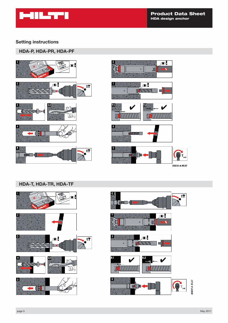
HDA-T, HDA-TR, HDA-TF
Setting instructions
HDA-P, HDA-PR, HDA-PF


![HDA Design anchor - Motek AS€¦ · Anchor bolt Nominal tensile strength f uk [N/mm²] 800 800 800 ... HDA Design anchor 09 / 2012 77 Anchor TE 24 a) TE 25 a) Anchor Anchor. HDA](https://static.fdocuments.us/doc/165x107/5b34310d7f8b9a436d8bbdfd/hda-design-anchor-motek-as-anchor-bolt-nominal-tensile-strength-f-uk-nmm.jpg)