HD-SDI Express User Training - Cosyco
22
HD-SDI Express User Training J.Egri 4/09 1
Transcript of HD-SDI Express User Training - Cosyco

HD-SDI ExpressUser Training
J.Egri 4/091

Features
• SDI interface• Supports 720p, 1080i and 1080p formats.• Supports SMPTE 292M serial interface operating at 1.485 Gbps.• Supports SMPTE 274M and 296M framing.• 75 ohm BNC coaxial connector.
• ExpressCard Interface• 54mm form factor.• PCIe x1 interface providing 235 Mbytes/sec of throughput.• Scatter/Gather DMA ( Direct Memory Access ) engine using 4K
pages.• Flow-thru pipelined architecture for low latency.
2

Features (cont.)
• Features• Operates in either YCrCb 4:2:2 - 20 bit, YCrCb 4:2:2 - 16 bit or
RGB - 24 bit modes.• Hardware based YCrCb 4:2:2 to RGB-24 color space conversion.• Hardware based RGB gain/offset with auto-white balance.• Hardware based RGB Lookup table with Gamma correction.• Histograms.• Hex pixel dump.• Capture single frame, multiple frames or AVI clips.• Save RAW, BMP, TIFF, JPEG or AVI files.• Firmware ‘Remote Upgrade’ capability.
3
4
Features(cont.)
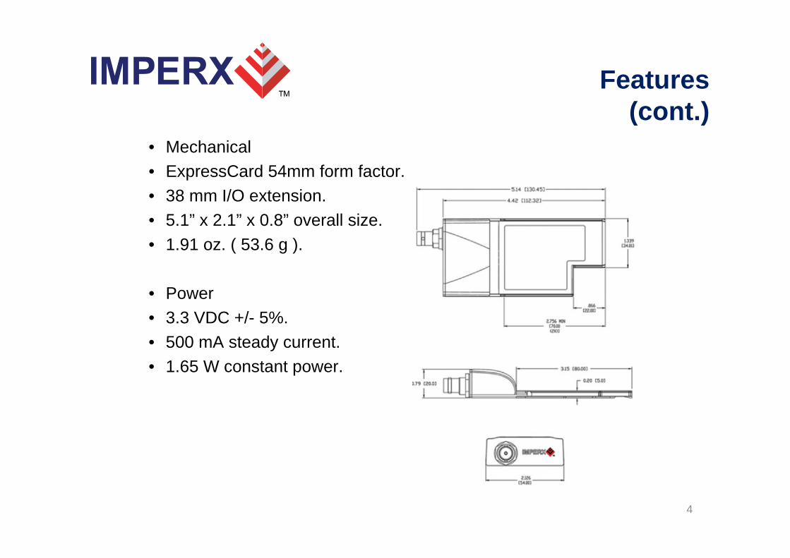
• Mechanical• ExpressCard 54mm form factor.• 38 mm I/O extension.• 5.1” x 2.1” x 0.8” overall size.• 1.91 oz. ( 53.6 g ).
• Power• 3.3 VDC +/- 5%.• 500 mA steady current.• 1.65 W constant power.

Main Menu
• Consists of a Menu bar, an Icon bar and a Status bar.
5

Menu Bar
6

Icon Bar
7

Status Bar
• Camera Rate Displays the real-time frame rate of the attached camera as measured at the input of the HD-SDI Express card.
• Grabbing Rate Displays the real-time rate at which frames are being transferred from the card into host memory.
• Grabbing Count Displays a running count of the total number of frames transferred into system memory. This counter is reset when ‘grabbing’ is stopped.
• Pixel Coordinates Indicates the x,y coordinates of the pixel at the current cursor position.• Pixel Value Indicates the value ( grayscale or RGB ) of the pixel at the current cursor position.• DMA Status Displays the real-time status of the DMA process as being either : ‘active’ or
‘inactive’. ‘Active’ indicates that the user has commanded the HD-SDI Express to acquire video data by clicking on the ‘Start Grab’ button and that the camera is providing valid framing.
‘Inactive’ indicates that either the user has commanded the HD-SDI Express to stop acquiring video data by clicking on the ‘Stop Grab’ button or that grabbing is
enabled but the camera is not providing valid framing.
• Camera Status Displays the real-time status of the attached camera as being either : ‘online’ or ‘offline’.
‘Online’ indicates that the camera is powered on, attached and providing a video clock via the SDI interface. ‘Offline’ indicates that the HD-SDI Express card is not receiving a video clock from the camera either because the camera is powered off or the SDI cable is disconnected.
8
Camera Parameters
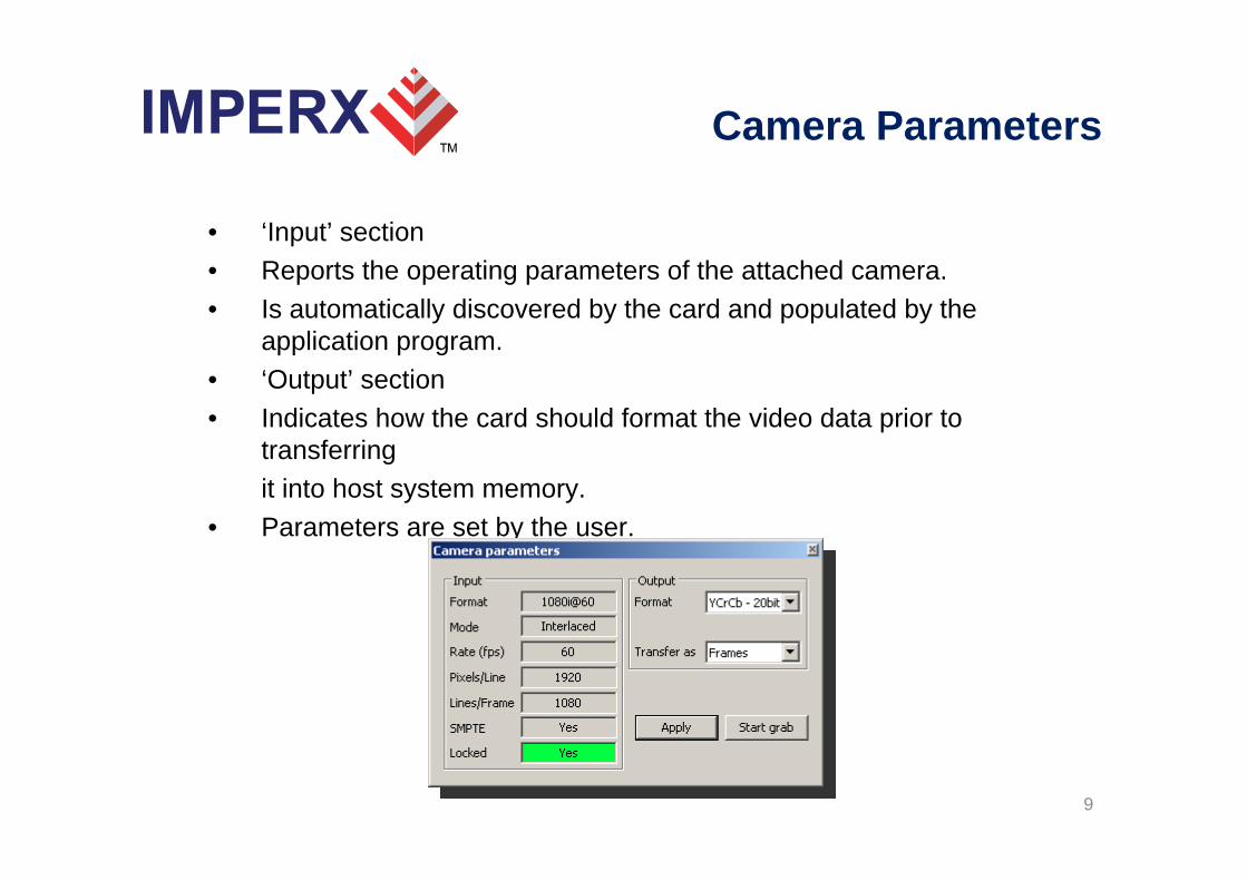
• ‘Input’ section • Reports the operating parameters of the attached camera.• Is automatically discovered by the card and populated by the
application program.• ‘Output’ section• Indicates how the card should format the video data prior to
transferringit into host system memory.
• Parameters are set by the user.
9

Color Space Converter
• This function is responsible for converting from YCrCb video data to the RGB-24 format.
• User can adjust the behavior of the color space converter function. • If RGB-24 mode is selected, then the CSC is performed on the card
and RGB-24 data is delivered from the card into host memory.• If either the YCrCb-20 or YCrCb-16 modes are selected, then YCrCb
data is delivered from the cardinto host memory and theCSC is performed byhost software.
10

RGB Control
• Programmable RGB Gain and Offset.• Automatic White Balance feature computes RGB gains.• If RGB-24 mode is selected then the RGB gain and offset are
performed on the card, otherwise they are performed by the host software.
11

RGB Lookup Table
• Modifies and transform the original video data into any arbitrary value.
• The ‘Gamma’ mode allows the user to select Gamma correction values for each of the R, G, B components.
• The ‘Pencil’ mode allows the user to draw the desired transfer function for each of the R, G, B components.
• LUT files can be created with Excel or any ASCII editor.• If RGB-24 mode is selected then the RGB lookup table is performed
on the card, otherwise it is performed by the host software.
12

Capture Settings
• Specifies file format for images saved to disk.• Specifies capture mode.
13

Single Frames
• Used to record one frame only.• Specify the path and filename for the recorded file.• Insert optional date/time/timestamp/text to be overlayed on image
saved.• The overlay text is destructive ( i.e. persistent ) to the image saved.
14

Series of Frames
• Used to record multiple frames.• Specify the path and filename for the recorded file.• Insert optional date/time/timestamp/text to be overlayed on images saved.• The overlay text is destructive ( i.e. persistent ) to the image saved.• Specify capture event frequency.• Specify capture duration for each event.• Specify capture limits.
15

Series of FramesExamples
• Example #1: To capture 5 frames, every 1.5 hours, over a 12 hour period.Capture event occurs: Capture every: 01 Hr 30 Min 00 SecCapture duration for each event: Limit number of frames to: 5Total capture: Limit total capture time to: 12 Hr 00 Min 00 Sec
• Example #2: To capture 5 minutes worth of images, every 15 minutes and not to exceed a total of 250 images.Capture event occurs: Capture every: 00 Hr 15 Min 00 SecCapture duration for each event: Limit capture time to: 00 Hr 05 Min 00 SecTotal capture: Limit total number of frames to: 250
• Example #3: To capture 10 frames, every 1 hour, over a 6 hour periodand not to exceed a total of 300 images.Capture event occurs: Capture every: 01 Hr 00 Min 00 SecCapture duration for each event: Limit number of frames to: 10Total capture: Limit total capture time to: 06 Hr 00 Min 00 Sec
Limit total number of frames to: 300
• Example #4: To capture continuously for a period of 2 hours and not toexceed a total of 100 images.
Capture event occurs: ContinuousTotal capture: Limit total capture time to: 02 Hr 00 Min 00 Sec
Limit total number of frames to: 100 16

AVI Capture
• Used to record AVI movies.• Specify the path and filename for the recorded file.• Insert optional date/time/timestamp/text to be overlayed on images
saved.• The overlay text is destructive ( i.e. persistent ) to the image saved.• Specify capture limits.• Specify codec compressor.• Searches hard drive for all installed
compressors.
17
Statistics
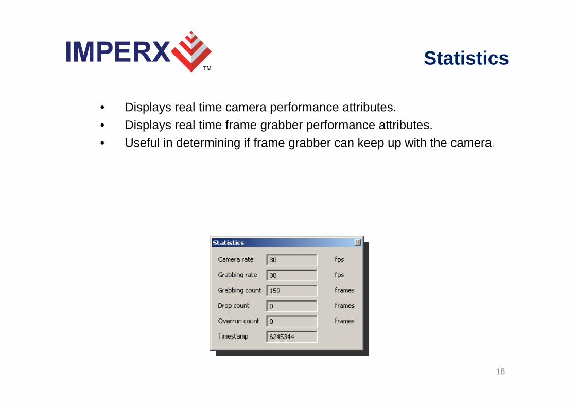
• Displays real time camera performance attributes.• Displays real time frame grabber performance attributes.• Useful in determining if frame grabber can keep up with the camera.
18

Hex Pixel Dump
• Displays a two-dimensional table of real-time pixel values, plotting row ( Y ) vs. column ( X ), for a bounded region of pixels.
• The YCrCb or RGB-24 pixel values are displayed depending on the operating mode.
• The background color of each cell is color coded.• Hovering the mouse over a given pixel reveals both the pixel’s
hexadecimal and integer component values.
19

Histogram
• Plots the histogram of the live image as afunction of pixel frequency ( Y-axis ) vs.pixel value ( X-axis ).
• The range of the pixel value, in the X-axis, depends on the mode selected.
• Displays three graphs: one per component.• When the YCrCb-20 or YCrCb-16 modes are
selected, it will display plots for the Y, Cr and Cbcomponents.
• When the RGB-24 mode is selected, it will display plots for the R, G and B components.
20

Player
• Allows the user to select pre-recorded images to view.• VCR-like controls are provided.
21

22
Remote Upgrade
• Card contains two non-volatile firmware images: ‘Factory’ and ‘Application’.
• Both images are programmed into the card during manufacturing.• Card loads the ‘factory’ image on power-on, which then runs and
loads the ‘application’ image ( if a valid ‘application’ image is present ).
• A ‘Remote Upgrade’ utility allows theuser to upgrade the card’s ‘application’firmware image in the field.
• User is supplied with a self-executable remote upgrade utility with the‘application’ firmware image embeddedin it.