HD Projector Eng
42
HD LCD-Projector Manual Time to build: 4 hours It‘s really a lot of fun to build this LCD projector. I had just the German manual and it took me forever to translate it. Therefore I will help you and wrote all my stuff down. I used the four bundles from www.diy-beamer.net : 1. Optic bundle 2. Housing bundle 3. Light bundle 4. Electronic bundle Table of Contents 01 Painting 02 02 Connector cover 03 03 230V cable 04 04 12V power supply 06 05 Controller board 08 06 ON / OFF by remote control 09 07 FTR – Fan Temperature Regulation 12 08 Connect FTR and ON/OFF circuit 15 09 Controller board assembly 16 10 Housing 19 11 Electronics assembly 20 12 Wiring 21 13 Finishing housing 23 14 Bulb assembly and IR cut filter 24 15 Assembly 1st Fresnel lens 26 16 Assembly LCD 28 17 Assembly 2nd Fresnel lens 32 18 Front Face Mirror assembly 33 19 Objective 35 20 Grills Plate 38 21 Lid 40 22 Schematic 42
-
Upload
digvijay-patil -
Category
Documents
-
view
222 -
download
0
Transcript of HD Projector Eng

HD LCD-Projector Manual
Time to build: 4 hours
It‘s really a lot of fun to build this LCD projector. I had just the German manual and it took me forever to translate it. Therefore I will help you and wrote all my stuff down. I used the four bundles from www.diy-beamer.net: 1. Optic bundle 2. Housing bundle 3. Light bundle 4. Electronic bundle Table of Contents
01 Painting 02 02 Connector cover 03 03 230V cable 04 04 12V power supply 06 05 Controller board 08 06 ON / OFF by remote control 09 07 FTR – Fan Temperature Regulation 12 08 Connect FTR and ON/OFF circuit 15 09 Controller board assembly 16 10 Housing 19 11 Electronics assembly 20 12 Wiring 21 13 Finishing housing 23 14 Bulb assembly and IR cut filter 24 15 Assembly 1st Fresnel lens 26 16 Assembly LCD 28 17 Assembly 2nd Fresnel lens 32 18 Front Face Mirror assembly 33 19 Objective 35 20 Grills Plate 38 21 Lid 40 22 Schematic 42

2
1. Painting
Paint all wood parts with black color. That creates a good finish and avaids scattered light. It is not essential but recommanded.
Finished parts.

3
2. Connector cover
Due to the combined cable you have to solder the cinch socket or you have to cut the connector panel. Mount the IR receiver with some hot glue, S-video socket with sheet-metal screw 6,5mm, and low heat device jack with Phillips screw 3x8mm and M3 nut.
Front.
low heat device jack Cinch S-video IR
low heat device jack Cinch S-video IR
4
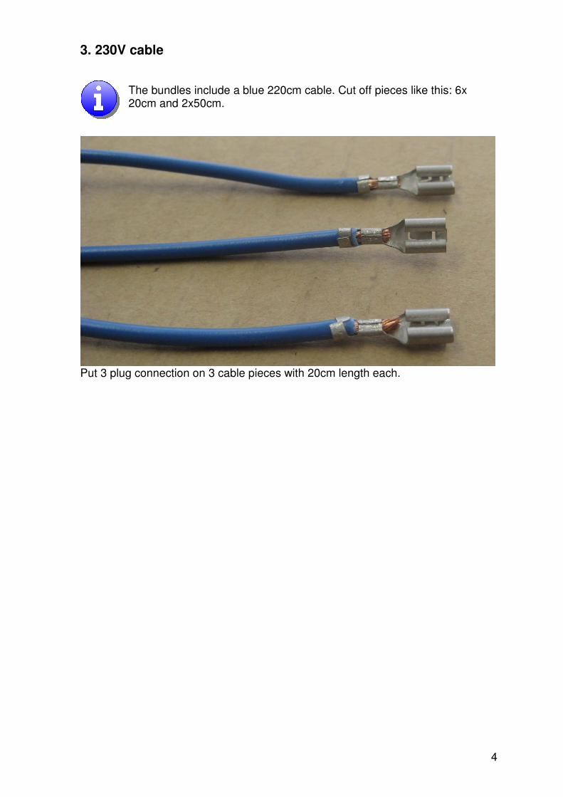
3. 230V cable
The bundles include a blue 220cm cable. Cut off pieces like this: 6x 20cm and 2x50cm.
Put 3 plug connection on 3 cable pieces with 20cm length each.
5
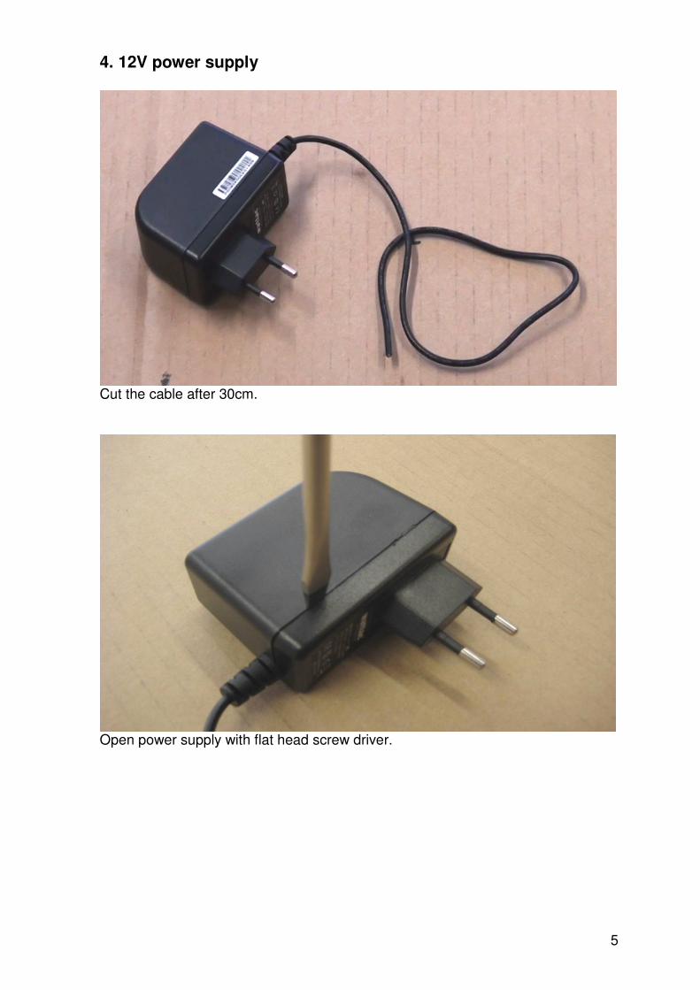
4. 12V power supply
Cut the cable after 30cm.
Open power supply with flat head screw driver.

6
Desolder white cable.
Cut another 2 blue cable pieces with 20cm length and solder them on the power supply like shown above. Don’t take the blue cables with plug connection

7
Cut pins.
Put blue cables through holes and close power supply pieces. Use some hot glue to seal it.

8
5. Controller board
Desolder 12V socket.
Before After
12V socket
Controller board
9
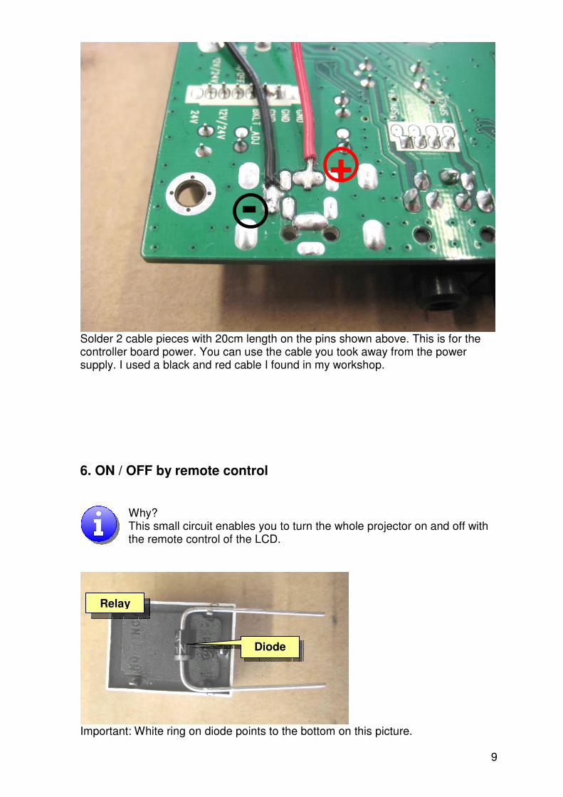
Solder 2 cable pieces with 20cm length on the pins shown above. This is for the controller board power. You can use the cable you took away from the power supply. I used a black and red cable I found in my workshop.
6. ON / OFF by remote control
Why? This small circuit enables you to turn the whole projector on and off with the remote control of the LCD.
Important: White ring on diode points to the bottom on this picture.
+ -
Relay
Diode
10
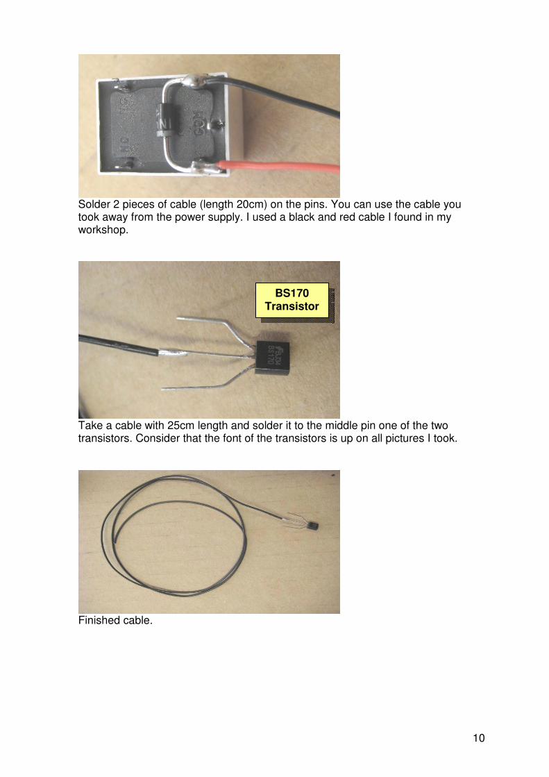
Solder 2 pieces of cable (length 20cm) on the pins. You can use the cable you took away from the power supply. I used a black and red cable I found in my workshop.
Take a cable with 25cm length and solder it to the middle pin one of the two transistors. Consider that the font of the transistors is up on all pictures I took.
Finished cable.
BS170 Transistor

11
Use the black cable on the right pin of the relay and solder it to the left pin of the transistor (font up).
Use one of the three blue cables with plug connection and solder it on the middle pin of the relay.
Relay Transistor

12
7. FTR – Fan Temperature Regulation
This small circiut controls the speed of the fans. The fans run if the temperature in the projector is bigger than 40° Celsius.
Take the 2nd transistor and the resistor and solder how it is shown in the picture.
Take another two pieces of 30cm long cable and solder it onto the temp sensor.
Take one of the cables coming from the temp sensor (doesn’t matter which) and solder it to the middle pin of the 2nd transistor.
Resisitor
Transistor
Temperature sensor

13
Cut or desolder the yellow cable on both fans.
Cut connector.

14
Finished fans.
Solder both red cables from the fans on the other cable coming from the temp sensor. Solder the black fan cables on the upper pin of the transistor (font up).
Cable coming from fans
Temp sensor
Transistor with Resistor

15
Finished FTR.
8. Connect FTR and ON/OFF circuit That part looks hard but if you look carefully at all the pictures it should be easy.
Important: The font on the left transistor is up and the font on the right one down.
FTR ON/OFF
Fan cable
Cable coming from temp sensor
Open wire
Cable to relay

16
9. Controller board assembly
Take the power supply and look at the black cable. The wire on the inside is positive and you have to connect it with the red cable from the controller board and another new 20cm long cable (if possible red). If you did not use a black and red cable make sure that you connect the inside wire with the wire coming from the pin with a plus (look page 9) The outside cable is negative and you have to connect it to the black (other) cable coming from the controller board and another new 20cm long cable (if possible black). Furthermore take the four screws out of the DVI and VGA connector (blue square)
Put the controller board through the connector cover and tighten the 4 screw back on.
open wires

17
Solder the open wires onto the FTR and ON/OFF circuit to supply the fans and the controller board with power. Take electrical tape or heat shrink to cover the solder points.
Yellow circle markes the cable coming from the Cinch and S-video sockets.
Red open wire
Black open wire
Fan cables
Both blue, not yet connected wires
Empty 2 pins on that side
Cable to relay
Signal Cable

18
Connect cables like shown in the picture above.
Finshed.
LVDS cable
LVDS
Blue open wires
Cable from IR receiver
White dot

19
10. Housing
Please work exact.
Screw sheet metal on back wall. Put the washer which is included in the package between the sheet metal and the wood. Mount the back wall (long wall with holes for two fans and connector cover) onto back wall. Notice slot and key principle. Use wood screws (included).
20mm
132mm
122mm
Mount like shown in the
picture Bottom plate
with notch

20
Sheet metal is heat protection. Reflector reflects just visible light. IR radiation gets through reflector.
11. Electronics assembly
Put fans and power supply through connector cover slot and mount connector cover with 8 sheet metal screws length 6,5mm (included in bundles).
Done!

21
Put fans, flush with the outside of the housing, in the holes. Consider the direction of the airflow. The right fan is supposed to blow cool air into the housing and the left fan is supposed to suck the hot air out of the housing.
12. Wiring
Cut two blue cable with length 50cm and connect them to the G12 bulb socket with luster terminal (included).
22
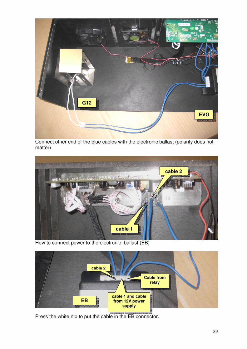
Connect other end of the blue cables with the electronic ballast (polarity does not matter)
How to connect power to the electronic ballast (EB)
Press the white nib to put the cable in the EB connector.
EB
EVG
G12
cable 1
cable 2
cable 2
cable 1 and cable from 12V power
supply
Cable from relay

23
Arrange EB, 12V power supply and relay like it is shown in the pictures and mount them with some hot glue.
The Signal Cable of the 2nd transistor is connected to the BKLITON / OFF pin of the controller board.
Signal Cable

24
13. Finishing housing
Mount all sides. Notice slot and key principle. Use wood screws (included).
Front wall
Side part
25
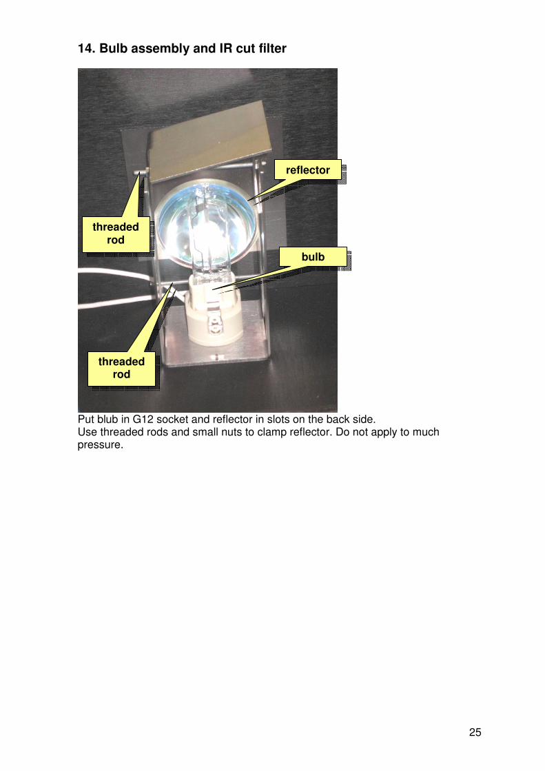
14. Bulb assembly and IR cut filter
Put blub in G12 socket and reflector in slots on the back side. Use threaded rods and small nuts to clamp reflector. Do not apply to much pressure.
threaded rod
threaded rod
reflector
bulb

26
Put condenser in slots on the front. If you want use threaded rods and small nuts to clamp reflector. Do not apply to much pressure.
Mount wood pieces like shown in the picture. Use some hot glue if necessary. Place IR cut filter.
35x20mm
246x20mm
47x114mm
threaded rod
condensor
27
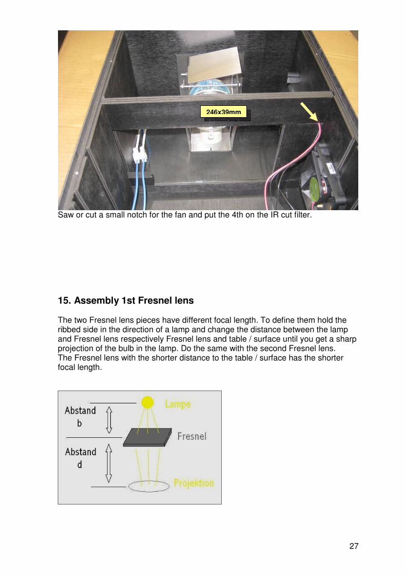
Saw or cut a small notch for the fan and put the 4th on the IR cut filter.
15. Assembly 1st Fresnel lens The two Fresnel lens pieces have different focal length. To define them hold the ribbed side in the direction of a lamp and change the distance between the lamp and Fresnel lens respectively Fresnel lens and table / surface until you get a sharp projection of the bulb in the lamp. Do the same with the second Fresnel lens. The Fresnel lens with the shorter distance to the table / surface has the shorter focal length.
246x39mm

28
Mount wood pieces like it is shown in the picture. The plain side of the Fresnel lens points to the condenser lens.
246x32mm
Fresnel lens with smaller shorter length
21x13mm 30x13mm
23x28mm
23x19mm
30x13mm
23x28mm

29
16. Assembly LCD
Pull 2 lugs away and remove foil.
Loosen screws on the sides.
LCD

30
Bend frame to remove the LED backlight. Be careful doing that. Do not bend the lugs next to the ribbon cable.
Remove lugs on LCD controller board.

31
Take backlight and LCD apart.
Put rubber on 246x33mm wood piece and cut it to the right length.
Backlight
LCD
246mm x 33mm

32
Mount the bottom bracket (19x121mm) with notch facing down and pull bulb cable through this hole. The 3mm thick cover has to be mounted on both bottom brackets (26x17mm and 36x17mm). Use some hot glue. This cover is important to avoid scattered light in your projection.
Connect the LVDS cable the way that the thin cables are like in the picture above.
19x121mm
26x17mm 240x17mm 3mm thick
36x17mm
30x121mm
LCD
Thin cables

33
Insert LCD from the top without pressure. Put the upper wood cover with rubber on top. Rubber on LCD.
17. Assembly 2nd Fresnel lens
Mount 2nd Fresnel lens with longer focal length the same way as the first one. Ribbed side shows to the LCD. Use the 23x128mm wood piece on the back side instead of the side brackets 23x19mm and 23x28mm.
Wood with rubber
21x13mm
30x13mm
23x128mm

34
18. Front Face Mirror assembly
Put mirror in holder like it is shown in the picture above.
Before you glue the mirror on the holder put some small piece of wood as underlay on the other side. This helps you to adjust the mirror perfect. It should be close to 90 degrees.
Mirror holder
Reflection side with blue
protection cover Bevelled edge
Underpacking

35
Use some hot glue to fix the mirror.
Use a knife to cut the protection foil close to the glue.

36
19. Objective
Glue felt on wood ring and cut off the rest.
Finshed part.
37
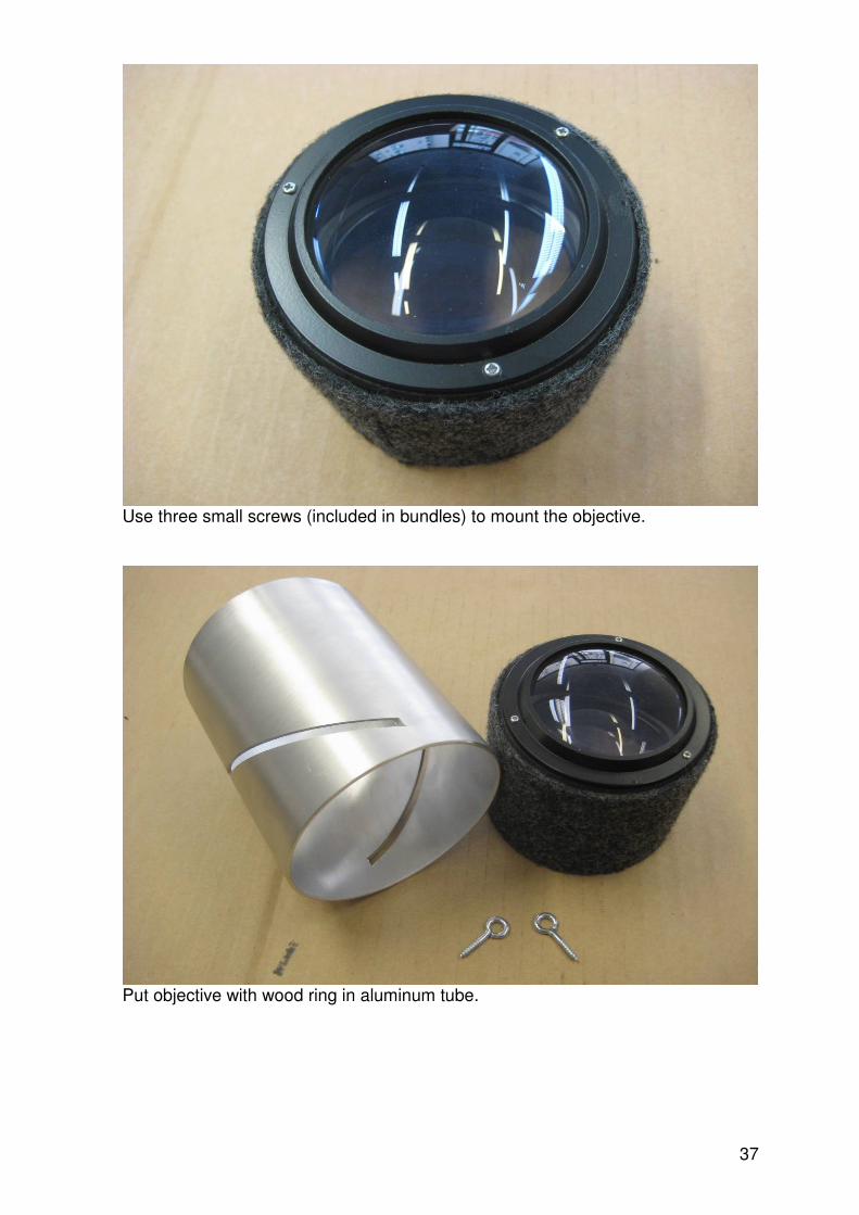
Use three small screws (included in bundles) to mount the objective.
Put objective with wood ring in aluminum tube.

38
Position the objective like it is shown above and screws a eyelet screws through the slot in the wood ring where the yellow arrow is. Tighten it until the last thread is hidden. Do the same with the other side.
Done.

39
Mount the aluminum tube with objective on the housing. Use some hot glue if necessary.
20. Grills Plate
Mount the four wood pieces like it is shown in the picture with some glue on the housing. Put the grill plate on top and mark the six holes with a pen. Remove the grill plate and pre-drill the holes about 10mm deep with a small drill bit.
115x10mm
210x10mm
105x10mm 115x10mm
40
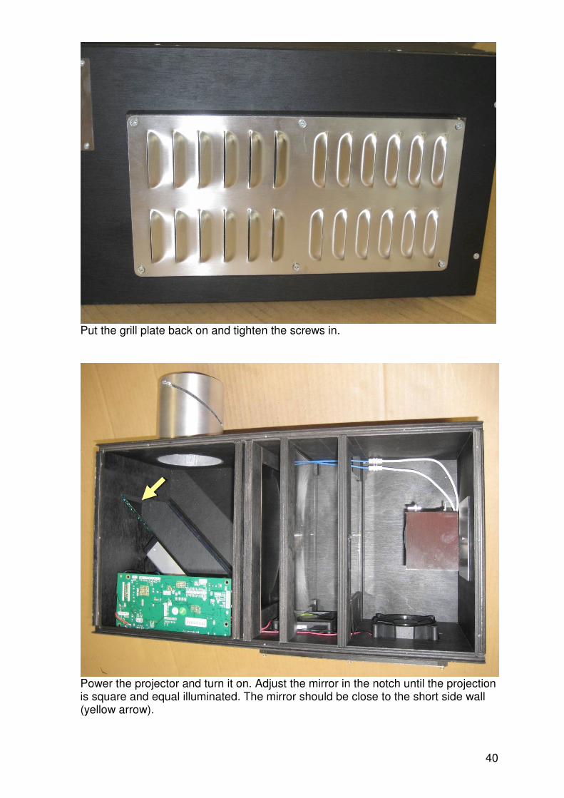
Put the grill plate back on and tighten the screws in.
Power the projector and turn it on. Adjust the mirror in the notch until the projection is square and equal illuminated. The mirror should be close to the short side wall (yellow arrow).

41
21. Lid
Put lid on the housing. Use the 19mm x 2,5mm screws which are included in the bundles. Position the side with the missing holes over the controller board. If you put a screw into the side of the controller board you might destroy it.
Done!
Some important information:
1. The projector shuts off after 10 seconds if you do not apply signal. That
means if you turn of the Video signal (for example DVD player) the projector shuts down as well.
2. If you turn off the projector you have to wait until the bulb cools down before you can turn it on again (about 3 minutes)
3. To choose the video signal source (DVI, VGA, S-Video, AV, HDMI) press MODE on the remote control and confirm with the right arrow key. NOT the OK key.
4. The small board with pushbuttons is not used. All the functions are controlled by the remote control.
No screw

42
22. Schematic