HD EXP STRESS ANALYSIS Chapter 2 Stress Rev September 2013+Assignment
24
Chapter 2 STRESS, STRAIN AND STRESS-STRAIN RELATIONSHIPS 1. INTRODUCTION 1 There are two main types of stress analyses. The first is conceptual, where the structure does not yet exist and the analyst is given reasonable leeway to define geometry, material, loads, and so on. The preeminent way of doing this nowadays is with the finite element method (FEM). The second analysis is where the structure (or a prototype) exists, and it is this particular structure that must be analyzed. Situations involving real structures and components are, by their very nature, only partially specified. Notation for stress components 1 From Doyle , Modern Experimental Stress Analysis, John Wiley & Sons, 2004. xx yz yx
description
Experimental stress analysis
Transcript of HD EXP STRESS ANALYSIS Chapter 2 Stress Rev September 2013+Assignment

Chapter 2
STRESS, STRAIN AND STRESS-STRAIN RELATIONSHIPS 1. INTRODUCTION1 There are two main types of stress analyses. The first is conceptual, where the structure does not yet exist and the analyst is given reasonable leeway to define geometry, material, loads, and so on. The preeminent way of doing this nowadays is with the finite element method (FEM). The second analysis is where the structure (or a prototype) exists, and it is this particular structure that must be analyzed. Situations involving real structures and components are, by their very nature, only partially specified.
Notation for stress components
1 From Doyle , Modern Experimental Stress Analysis, John Wiley & Sons, 2004.
xxyz
yx
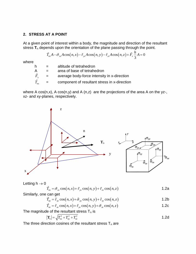
2. STRESS AT A POINT At a given point of interest within a body, the magnitude and direction of the resultant stress Tn depends upon the orientation of the plane passing through the point.
cos , cos , cos , 03
nx xx yx zx x
hT A A n x A n y A n z F A
where h = altitude of tetrahedron A = area of base of tetrahedron
xF = average body-force intensity in x-direction
nxT = component of resultant stress in x-direction
where A cos(n,x), A cos(n,y) and A (n,z) are the projections of the area A on the yz-, xz- and xy-planes, respectively.
Letting h 0
cos , cos , cos ,nx xx yx zxT n x n y n z 1.2a
Similarly, one can get
cos , cos , cos ,ny xy yy zyT n x n y n z 1.2b
cos , cos , cos ,nz xz yz zzT n x n y n z 1.2c
The magnitude of the resultant stress Tn is
2 2 2
n nx ny nzT T T T 1.2d
The three direction cosines of the resultant stress Tn are
n
z
Tn
x
y

cos , nxn
n
TT x
T
cos ,ny
n
n
TT y
T
cos , nzn
n
TT z
T
The normal stress n and the shearing stress n which act on the plane considered are
cos ,n n nT n T
and
sin ,n n nT n T
The angle between the resultant stress vector Tn and the vector normal to the plane n is given by
cos , cos , cos , cos , cos , cos , cos ,n n n nT n T x x n T y y n T z z n
Also
cos , cos , cos ,n nx ny nzT x n T y n T z n
and
2 2
n n nT
3. STRESS EQUATION OF EQUILIBRIUM Summation of forces in the x-direction using Fig.1a:2
0
yxxxxx xx yx yx
zxzx zx x
dx dydz dy dxdzx y
dz dxdz F dxdydzz
Dividing through by dxdydz gives
0yxxx zx
xFx y z
1.3a
Similarly, by considering the force and the stress components in the y and z directions, it can be established in a similar fashion that:
2 From Dally, J.W., Riley, W.F., Experimental Stress Analysis, (4th Edition)., College House Enterprise, 2005.
0xy yy zy
yFx y z
1.3b
0yzxz zz
zFx y z
1.3c
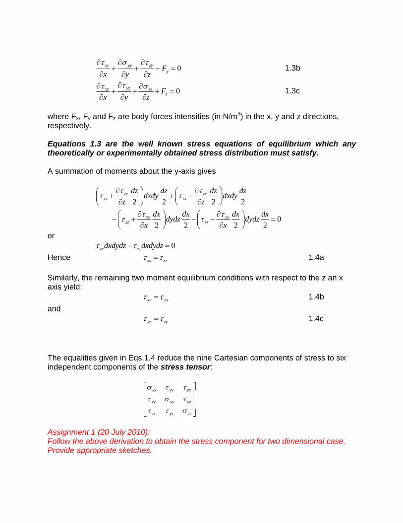
where Fx, Fy and Fz are body forces intensities (in N/m3) in the x, y and z directions, respectively. Equations 1.3 are the well known stress equations of equilibrium which any theoretically or experimentally obtained stress distribution must satisfy. A summation of moments about the y-axis gives
2 2 2 2
02 2 2 2
zx zxzx zx
xz xzxz xz
dz dz dz dzdxdy dxdy
z z
dx dx dx dxdydz dydz
x x
or
0zx xzdxdydz dxdydz
Hence zx xz 1.4a
Similarly, the remaining two moment equilibrium conditions with respect to the z an x axis yield:
xy yx 1.4b
and
yz zy 1.4c
The equalities given in Eqs.1.4 reduce the nine Cartesian components of stress to six independent components of the stress tensor:
xx xy zx
xy yy yz
zx yz zz
Assignment 1 (20 July 2010): Follow the above derivation to obtain the stress component for two dimensional case. Provide appropriate sketches.
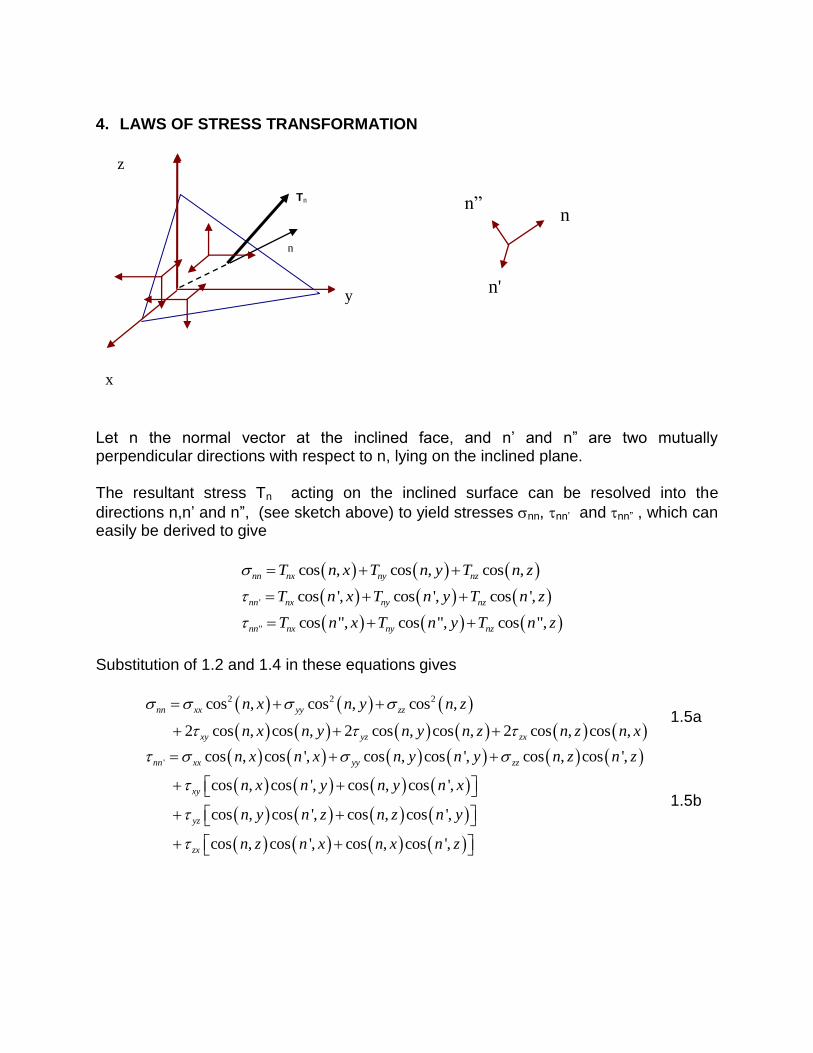
4. LAWS OF STRESS TRANSFORMATION
Let n the normal vector at the inclined face, and n’ and n” are two mutually perpendicular directions with respect to n, lying on the inclined plane. The resultant stress Tn acting on the inclined surface can be resolved into the
directions n,n’ and n”, (see sketch above) to yield stresses nn, nn’ and nn” , which can easily be derived to give
cos , cos , cos ,nn nx ny nzT n x T n y T n z
' cos ', cos ', cos ',nn nx ny nzT n x T n y T n z
" cos ", cos ", cos ",nn nx ny nzT n x T n y T n z
Substitution of 1.2 and 1.4 in these equations gives
2 2 2cos , cos , cos ,
2 cos , cos , 2 cos , cos , 2 cos , cos ,
nn xx yy zz
xy yz zx
n x n y n z
n x n y n y n z n z n x
1.5a
' cos , cos ', cos , cos ', cos , cos ',
cos , cos ', cos , cos ',
cos , cos ', cos , cos ',
cos , cos ', cos , cos ',
nn xx yy zz
xy
yz
zx
n x n x n y n y n z n z
n x n y n y n x
n y n z n z n y
n z n x n x n z
1.5b
n
Tn
x
y
z
n”
n'
n

" cos , cos ", cos , cos ", cos , cos ",
cos , cos ", cos , cos ",
cos , cos ", cos , cos ",
cos , cos ", cos , cos ",
nn xx yy zz
xy
yz
zx
n x n x n y n y n z n z
n x n y n y n x
n y n z n z n y
n z n x n x n z
1.5c
Equations 1.5 can be used to determine the normal- and shear-stress components at a point expressed in any set of chosen Cartesian frame of reference if the stresses associated with one frame of reference are known.
Expressions for the stress components x’x’ , y’y’ , z’z’ , x’y’ , y’z’ and z’x’ can be obtained directly from equ. 1.5a or 1.5b by employing the following procedure.
To determine x’x’ , select a plane having an outer normal n coincident with x’. The
resultant stress Tn = Tx’ is associated with this plane. The normal stress x’x’ can be obtained directly from 1.5a by substituting x’ for n :
2 2 2
' ' cos ', cos ', cos ',
2 cos ', cos ', 2 cos ', cos ', 2 cos ', cos ',
x x xx yy zz
xy yz zx
x x x y x z
x x x y x y x z x z x x
1.6a
Following similar procedure, substitution of n with y’ or z’ will yield expressions for y’y’ ,
and z’z’ , respectively
2 2 2
' ' cos ', cos ', cos ',
2 cos ', cos ', 2 cos ', cos ', 2 cos ', cos ',
y y yy zz xx
yz zx xy
y y y z y x
y y y z y z y x y x y y
1.6b
2 2 2
' ' cos ', cos ', cos ',
2 cos ', cos ', 2 cos ', cos ', 2 cos ', cos ',
z z zz xx yy
zx xy yz
z z z x z y
z z z x z x z y z y z z
1.6c
The shear components x’y’ is obtained by selecting a plane having outer normal n coincident with x’ and the in-plane direction n’ coincident with y’.
The shear-stress x’y’ is obtained from 1.5b by substituting x’ for n and y’ for n’ :
' ' cos ', cos ', cos ', cos ', cos ', cos ',
cos ', cos ', cos ', cos ',
cos ', cos ', cos ', cos ',
cos ', cos ', cos ', cos ',
x y xx yy zz
xy
yz
zx
x x y x x y y y x z y z
x x y y x y y x
x y y z x z y y
x z y x x x y z
1.6d
' ' cos ', cos ', cos ', cos ', cos ', cos ',
cos ', cos ', cos ', cos ',
cos ', cos ', cos ', cos ',
cos ', cos ', cos ', cos ',
y z yy zz xx
yz
zx
xy
y y z y y z z z y x z x
y y z z y z z y
y z z x y x z z
y x z y y y z x
1.6e
' ' cos ', cos ', cos ', cos ', cos ', cos ',
cos ', cos ', cos ', cos ',
cos ', cos ', cos ', cos ',
cos ', cos ', cos ', cos ',
z x zz xx yy
zx
xy
yz
z z x z z x x x z y x y
z z x x z x x z
z x x y z y x x
z y x z z z x y
1.6f
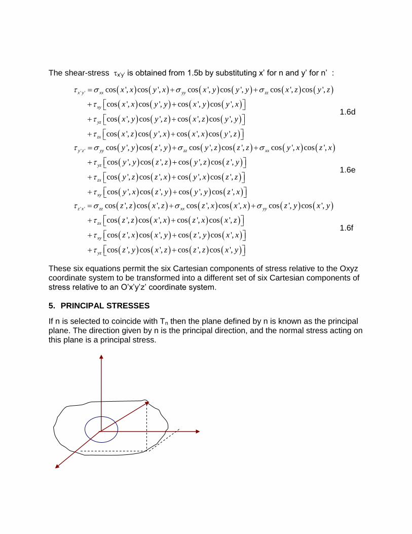
These six equations permit the six Cartesian components of stress relative to the Oxyz coordinate system to be transformed into a different set of six Cartesian components of stress relative to an O’x’y’z’ coordinate system. 5. PRINCIPAL STRESSES
If n is selected to coincide with Tn then the plane defined by n is known as the principal plane. The direction given by n is the principal direction, and the normal stress acting on this plane is a principal stress.
P
cos ,nx nT n x
cos ,ny nT n y a
cos ,nz nT n z
Substitute eq.1.2 into a, and get
cos , cos , cos , cos ,xx yx zx nn x n y n z n x
cos , cos , cos , cos ,xy yy zy nn x n y n z n y b
cos , cos , cos , cos ,xz yx zz nn x n y n z n z
Rearrangement gives
cos , cos , cos , 0xx n yx zxn x n y n z
cos , cos , cos , 0xy yy n zxn x n y n z e
cos , cos , cos , 0xz yz zz nn x n y n z
Solving for the direction cosines, say cos(n,x):
0
0
0cos ,
yx zx
yy n zy
yz zz n
xx n yx zx
yx yy n zy
xz yz zz n
n x
e
Nontrivial solutions for direction cosines of the principal plane exist only if the determinant of the denominator above is zero:
0
xx n yx zx
yx yy n zy
xz yz zz n
Expanding the determinant gives
3 2
2 2 2
2 2 2 2 0
n xx yy zz n
xx yy yy zz zz xx xy yz zx n
xx yy zz xx yz yy zx zz xy xy yz zx
1.7
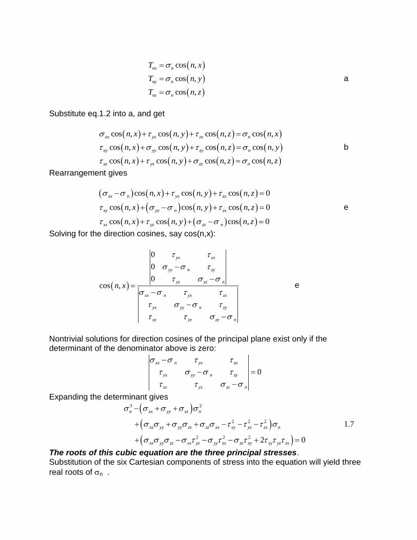
The roots of this cubic equation are the three principal stresses. Substitution of the six Cartesian components of stress into the equation will yield three
real roots of n .

Three possible solutions:
1. If 1 . 2 . and 3 are distinct, then n1,n2 and n3 are unique and mutually perpendicular.
2. If 1 = 2 ≠ 3 , then n3 is unique, and every direction perpendicular to n3 is a
principal direction associated with 1 = 2 .
3. If 1 = 2 = 3 , then a hydrostatic state on stress exists and every direction is a principal direction.
Once the three principal stresses have been obtained from equ. 1.7, they can be substituted individually into equs. C to give three sets of simultaneous equations. Note also that the following relationship for the direction cosines prevails3
2 2 2cos , cos , cos , 1n x n y n z f
Equs. (c) along with Equ. (f) can be solved to give the three sets of direction cosines defining the principal planes.
It is very useful to order the principal stresses so that 1 2 3 . The tensile stresses
are considered positive and the compressive stresses are considered negative. Stress Invariants
State of stress can be defined by its six Cartesian stress components with respect to any arbitrary Cartesian coordinate system Oxyz. The relationships between these stresses expressed in one Cartesian coordinate system to another is given by Equ. (1.6). Three other relations exist which are called the three invariants of stress.
3 Prove equ. f (Assignement 2- 20 July 2010)
n
Tn

To appreciate such notion, consider equ. 1.7 which is the cubic equation for the
principal stresses 1, 2, and 3 as the three roots of n in equ. (1.7)
3 2 2 2 2
2 2 2 2 0
n xx yy zz n xx yy yy zz zz xx xy yz zx n
xx yy zz xx yz yy zx zz xy xy yz zx
1.7
The principal stresses 1, 2, and 3 for any state of stress at a point in a structure should be independent of the Cartesian coordinate system chosen!. Therefore, the coefficients of Equ. (1.7) which contains the Cartesian components of the stresses must also be independent or invariant to the coordinate system. Hence, from Equ. (1.7) it is clear that:
1 ' ' ' ' ' 'xx yy zz x x y y z zI
2 2 2
2
2 2 2
' ' ' ' ' ' ' ' ' ' ' ' ' ' ' ' ''
xx yy yy zz zz xx xy yz zx
x x y y y y z z z z x x x y y z z x
I
1.8
2 2 2
3
2 2 2
' ' ' ' ' ' ' ' ' ' ' ' ' ' ' ' ' ' ' ' ' ' ' '
2
2
xx yy zz xx yz yy zx zz xy xy yz zx
x x y y z z x x y z y y z x z z x y x y y z z x
I
I1, I2 and I3 are known as the first, second and third invariants of stress, respectively. If
the Oxyz coordinate system is chosen to be coincident with the principal stresses 1, 2,
and 3 , Equs. 1.8 reduce to
1 1 2 3I
2 1 2 2 3 3 1I 1.9
3 1 2 3I
Assignment 3 (20 July 2010)
Simplify (Rederive) the above derivation for the three stress invariants for two-dimensional case
6. MOHR’S CIRCLE
For two dimensional stress fields where 0zz zx yz , z’ is coincident with z, and
the angle between x and x’ is , Equs. (1.6a) to (1.6f) reduce to
2 2
' ' cos sin 2 sin cos
cos 2 sin 22 2
x x xx yy xy
xx yy xx yy
xy
1.11a
2 2
' ' cos sin 2 sin cos
cos 2 sin 22 2
y y yy xx xy
xx yy xx yy
xy
1.11b
2 2
' ' cos sin cos sin cos sin
sin 2 cos 22
x y xx yy xy
yy xx
xy
1.11c
' ' ' ' ' ' 0z z z x y z 1.11d
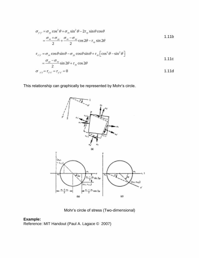
This relationship can graphically be represented by Mohr’s circle.
Mohr’s circle of stress (Two-dimensional)
Example: Reference: MIT Handout (Paul A. Lagace © 2007)
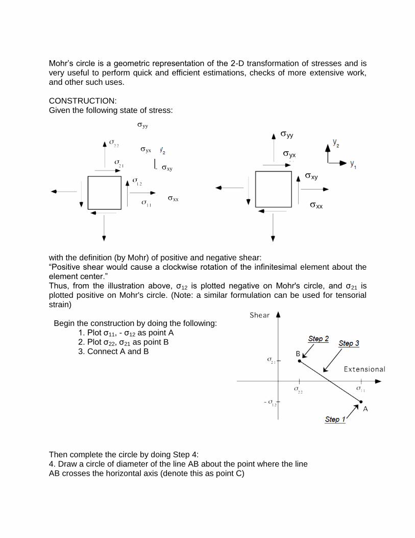
Mohr’s circle is a geometric representation of the 2-D transformation of stresses and is very useful to perform quick and efficient estimations, checks of more extensive work, and other such uses. CONSTRUCTION: Given the following state of stress:
with the definition (by Mohr) of positive and negative shear: “Positive shear would cause a clockwise rotation of the infinitesimal element about the element center.” Thus, from the illustration above, σ12 is plotted negative on Mohr's circle, and σ21 is plotted positive on Mohr's circle. (Note: a similar formulation can be used for tensorial strain)
Then complete the circle by doing Step 4: 4. Draw a circle of diameter of the line AB about the point where the line AB crosses the horizontal axis (denote this as point C)
xx
yy
xy
yx
xx
yy
xy
yx
Begin the construction by doing the following: 1. Plot σ11, - σ12 as point A 2. Plot σ22, σ21 as point B 3. Connect A and B
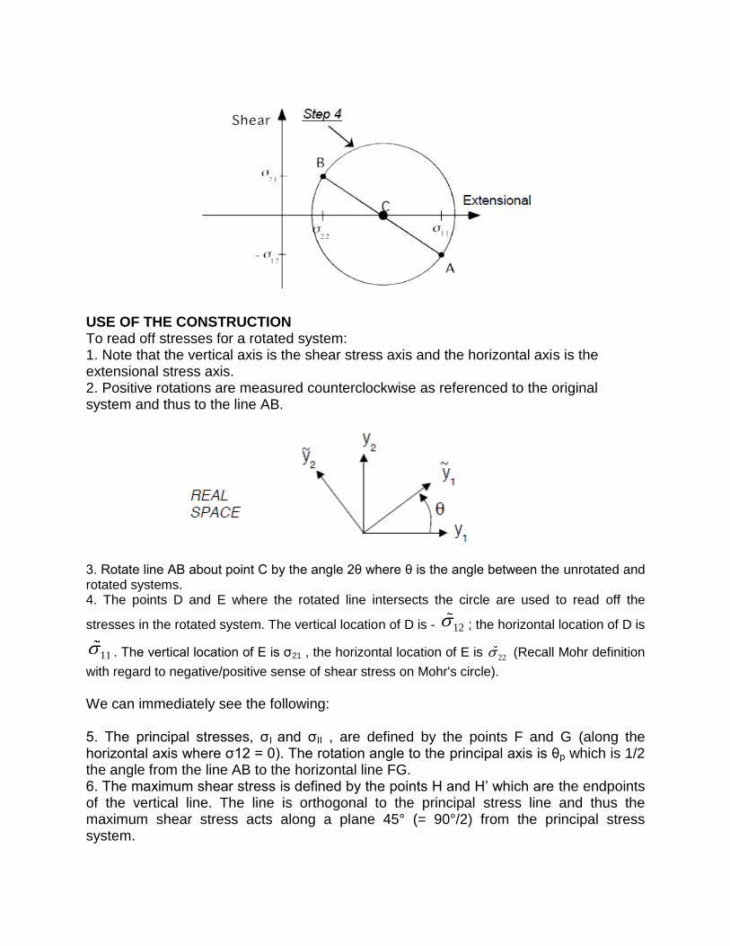
USE OF THE CONSTRUCTION To read off stresses for a rotated system: 1. Note that the vertical axis is the shear stress axis and the horizontal axis is the extensional stress axis. 2. Positive rotations are measured counterclockwise as referenced to the original system and thus to the line AB.
3. Rotate line AB about point C by the angle 2θ where θ is the angle between the unrotated and rotated systems. 4. The points D and E where the rotated line intersects the circle are used to read off the
stresses in the rotated system. The vertical location of D is - 12 ; the horizontal location of D is
11 . The vertical location of E is σ21 , the horizontal location of E is 22 (Recall Mohr definition
with regard to negative/positive sense of shear stress on Mohr's circle).
We can immediately see the following: 5. The principal stresses, σI and σII , are defined by the points F and G (along the horizontal axis where σ12 = 0). The rotation angle to the principal axis is θp which is 1/2 the angle from the line AB to the horizontal line FG. 6. The maximum shear stress is defined by the points H and H’ which are the endpoints of the vertical line. The line is orthogonal to the principal stress line and thus the maximum shear stress acts along a plane 45° (= 90°/2) from the principal stress system.

Full two-dimensional stress transformation equations (θ as on figure on p.13):
F G F G
H’
H
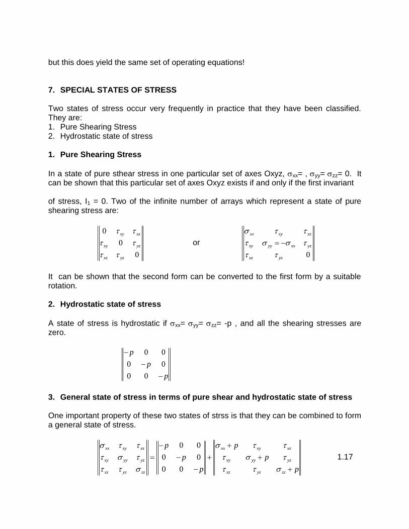
but this does yield the same set of operating equations! 7. SPECIAL STATES OF STRESS Two states of stress occur very frequently in practice that they have been classified. They are: 1. Pure Shearing Stress 2. Hydrostatic state of stress 1. Pure Shearing Stress
In a state of pure sthear stress in one particular set of axes Oxyz, xx= , yy= zz= 0. It can be shown that this particular set of axes Oxyz exists if and only if the first invariant of stress, I1 = 0. Two of the infinite number of arrays which represent a state of pure shearing stress are:
0
0
0
xy xz
xy yz
xz yz
or
0
xx xy xz
xy yy xx yz
xz yz
It can be shown that the second form can be converted to the first form by a suitable rotation. 2. Hydrostatic state of stress
A state of stress is hydrostatic if xx= yy= zz= -p , and all the shearing stresses are zero.
0 0
0 0
0 0
p
p
p
3. General state of stress in terms of pure shear and hydrostatic state of stress One important property of these two states of strss is that they can be combined to form a general state of stress.
0 0
0 0
0 0
xx xy xz xx xy xz
xy yy yz xy yy yz
xz yz zz xz yz zz
p p
p p
p p
1.17

Or: General state of stress = hydrostatic state of stress + state of pure shearing stress However, the third array represents a state of pure shear stress if and only if its first stress invariant is zero, i.e.
1 0xx yy zzI p p p
and hence
1
3xx yy zzp
Attachments:
From: http://www.efunda.com/formulae/solid_mechanics/mat_mechanics/mohr_circle.cfm
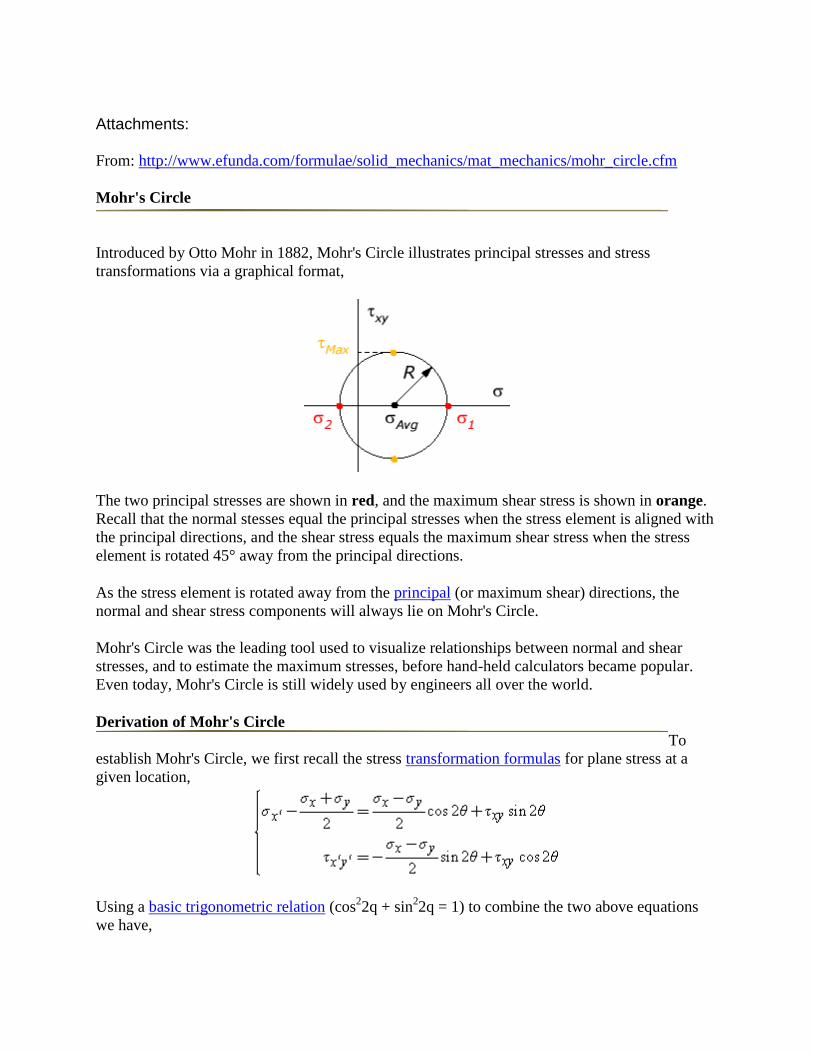
Mohr's Circle
Introduced by Otto Mohr in 1882, Mohr's Circle illustrates principal stresses and stress
transformations via a graphical format,
The two principal stresses are shown in red, and the maximum shear stress is shown in orange.
Recall that the normal stesses equal the principal stresses when the stress element is aligned with
the principal directions, and the shear stress equals the maximum shear stress when the stress
element is rotated 45° away from the principal directions.
As the stress element is rotated away from the principal (or maximum shear) directions, the
normal and shear stress components will always lie on Mohr's Circle.
Mohr's Circle was the leading tool used to visualize relationships between normal and shear
stresses, and to estimate the maximum stresses, before hand-held calculators became popular.
Even today, Mohr's Circle is still widely used by engineers all over the world.
Derivation of Mohr's Circle
To
establish Mohr's Circle, we first recall the stress transformation formulas for plane stress at a
given location,
Using a basic trigonometric relation (cos22q + sin
22q = 1) to combine the two above equations
we have,
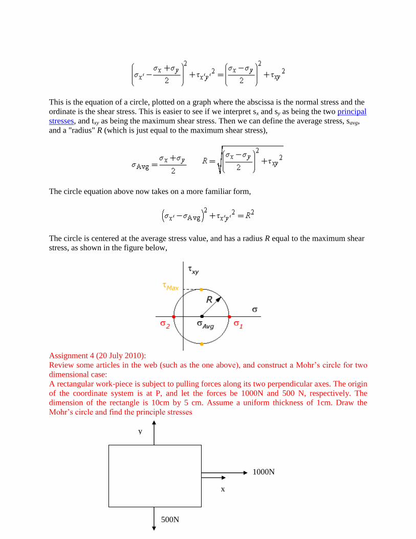
This is the equation of a circle, plotted on a graph where the abscissa is the normal stress and the
ordinate is the shear stress. This is easier to see if we interpret sx and sy as being the two principal
stresses, and txy as being the maximum shear stress. Then we can define the average stress, savg,
and a "radius" R (which is just equal to the maximum shear stress),
The circle equation above now takes on a more familiar form,
The circle is centered at the average stress value, and has a radius R equal to the maximum shear
stress, as shown in the figure below,
Assignment 4 (20 July 2010):
Review some articles in the web (such as the one above), and construct a Mohr’s circle for two
dimensional case:
A rectangular work-piece is subject to pulling forces along its two perpendicular axes. The origin
of the coordinate system is at P, and let the forces be 1000N and 500 N, respectively. The
dimension of the rectangle is 10cm by 5 cm. Assume a uniform thickness of 1cm. Draw the
Mohr’s circle and find the principle stresses
y
x
500N
x
1000N P
EXAMPLE The Problem In the field of Mechanical & Civil engineering determining the stresses and where they occur is
very important. For those who are not familiar with the term 'stress' : Stress is the resistance to
the applied force on a body per unit area. If a force of 'F' is acted upon a body of area 'A' then the
stress on that body equals to F/A. There are many types of forces as well as stresses according to
the application of different forces. Among them, one is direct force applied directly on a
particular point of a body. If the applied force tries to compress the body then it is compressive
force otherwise tensile, thus the stress due to this force is either compressive stress or tensile
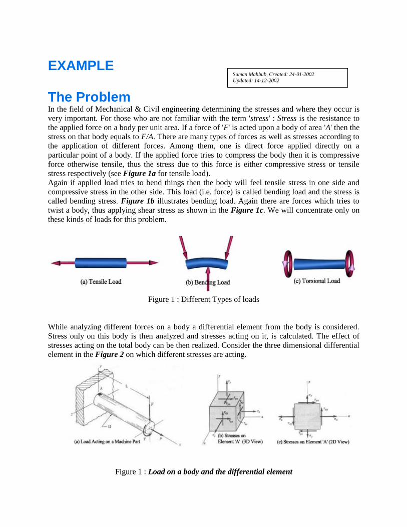
stress respectively (see Figure 1a for tensile load).
Again if applied load tries to bend things then the body will feel tensile stress in one side and
compressive stress in the other side. This load (i.e. force) is called bending load and the stress is
called bending stress. Figure 1b illustrates bending load. Again there are forces which tries to
twist a body, thus applying shear stress as shown in the Figure 1c. We will concentrate only on
these kinds of loads for this problem.
Figure 1 : Different Types of loads
While analyzing different forces on a body a differential element from the body is considered.
Stress only on this body is then analyzed and stresses acting on it, is calculated. The effect of
stresses acting on the total body can be then realized. Consider the three dimensional differential
element in the Figure 2 on which different stresses are acting.
Figure 1 : Load on a body and the differential element
Suman Mahbub, Created: 24-01-2002
Updated: 14-12-2002
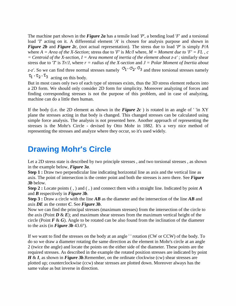
The machine part shown in the Figure 2a has a tensile load 'P', a bending load 'F' and a torsional
load 'T' acting on it. A differential element 'A' is chosen for analysis purpose and shown in
Figure 2b and Figure 2c, (not actual representation). The stress due to load 'P' is simply P/A
where A = Area of the X-Section; stress due to 'F' is Mc/I where, M = Moment due to 'F' = FL , c
= Centroid of the X-section, I = Area moment of inertia of the element about z-z' ; similarly shear
stress due to 'T' is Tr/J, where r = radius of the X-section and J = Polar Moment of Inertia about
z-z'. So we can find three normal stresses namely and three torsional stresses namely
acting on this body.
But in most cases only two of each type of stresses exists, thus the 3D stress element reduces into
a 2D form. We should only consider 2D form for simplicity. Moreover analyzing of forces and
finding corresponding stresses is not the purpose of this problem, and in case of analyzing,
machine can do a little then human.
If the body (i.e. the 2D element as shown in the Figure 2c ) is rotated in an angle of ' 'in XY
plane the stresses acting in that body is changed. This changed stresses can be calculated using
simple force analysis. The analysis is not presented here. Another approach of representing the
stresses is the Mohr's Circle - devised by Otto Mohr in 1882. It's a very nice method of
representing the stresses and analyze where they occur, so it's used widely.
Drawing Mohr's Circle
Let a 2D stress state is described by two principle stresses , and two torsional stresses , as shown
in the example below, Figure 3a.
Step 1 : Draw two perpendicular line indicating horizontal line as axis and the vertical line as
axis. The point of intersection is the center point and both the stresses is zero there. See Figure
3b below.
Step 2 : Locate points ( , ) and ( , ) and connect them with a straight line. Indicated by point A
and B respectively in Figure 3b.
Step 3 : Draw a circle with the line AB as the diameter and the intersection of the line AB and
axis DE as the center C. See Figure 3b.
Now we can find the principal stresses (maximum stresses) from the intersection of the circle to
the axis (Point D & E); and maximum shear stresses from the maximum vertical height of the
circle (Point F & G). Angle to be rotated can be also found from the inclination of the diameter
to the axis (in Figure 3b 43.6°).
If we want to find the stresses on the body at an angle ' ' rotation (CW or CCW) of the body. To
do so we draw a diameter rotating the same direction as the element in Mohr's circle at an angle
2 (twice the angle) and locate the points on the either side of the diameter. These points are the
required stresses. As described in the example the rotated position stresses are indicated by point
H & I, as shown in Figure 3b.Remember, on the ordinate clockwise (cw) shear stresses are
plotted up; counterclockwise (ccw) shear stresses are plotted down. Moreover always has the
same value as but inverse in direction.
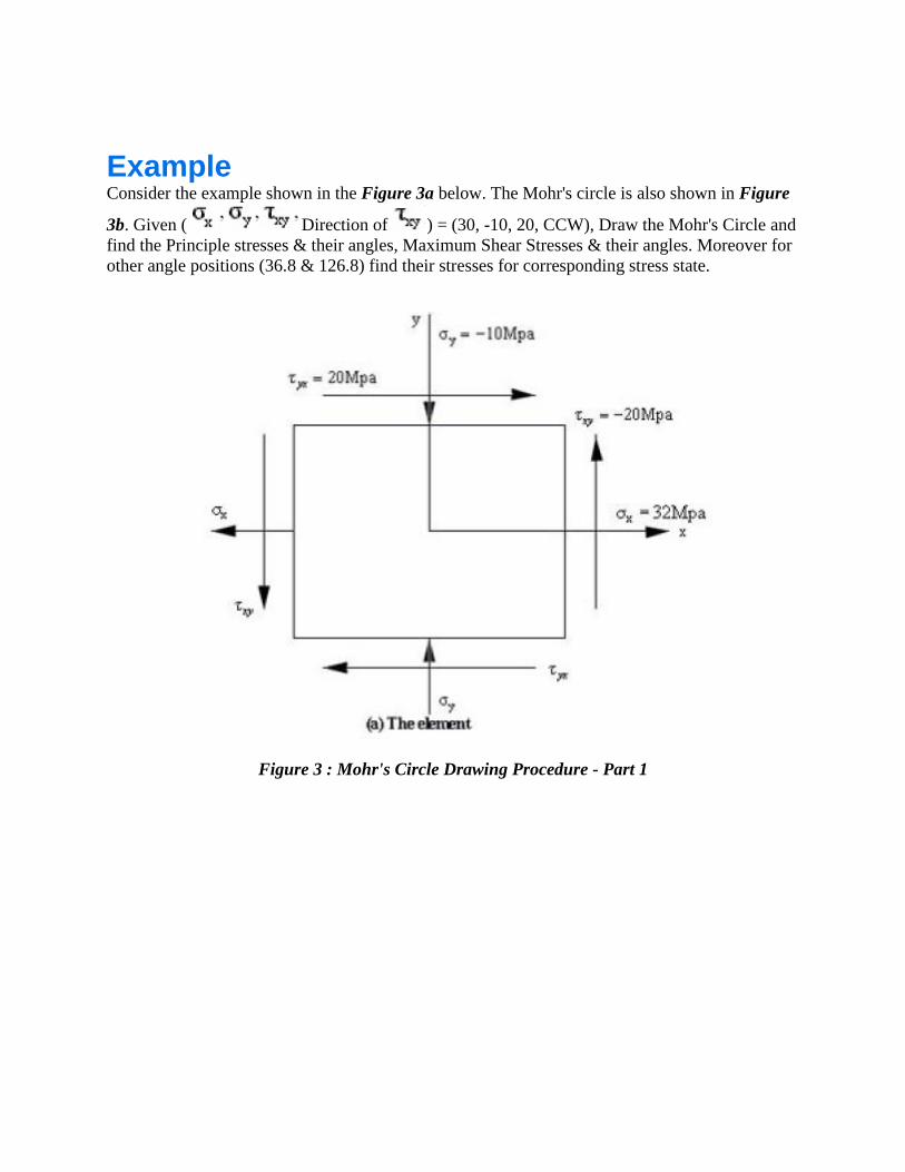
Example Consider the example shown in the Figure 3a below. The Mohr's circle is also shown in Figure
3b. Given ( Direction of ) = (30, -10, 20, CCW), Draw the Mohr's Circle and
find the Principle stresses & their angles, Maximum Shear Stresses & their angles. Moreover for
other angle positions (36.8 & 126.8) find their stresses for corresponding stress state.
Figure 3 : Mohr's Circle Drawing Procedure - Part 1
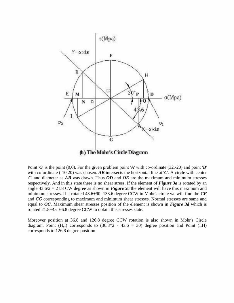
Point 'O' is the point (0,0). For the given problem point 'A' with co-ordinate (32,-20) and point 'B'
with co-ordinate (-10,20) was chosen. AB intersects the horizontal line at 'C'. A circle with center
'C' and diameter as AB was drawn. Thus OD and OE are the maximum and minimum stresses
respectively. And in this state there is no shear stress. If the element of Figure 3a is rotated by an
angle 43.6/2 = 21.8 CW degree as shown in Figure 3c the element will have this maximum and
minimum stresses. If it rotated 43.6+90=133.6 degree CCW in Mohr's circle we will find the CF
and CG corresponding to maximum and minimum shear stresses. Normal stresses are same and
equal to OC. Maximum shear stresses position of the element is shown in Figure 3d which is
rotated 21.8+45=66.8 degree CCW to obtain this stresses state.
Moreover position at 36.8 and 126.8 degree CCW rotation is also shown in Mohr's Circle
diagram. Point (H,I) corresponds to (36.8*2 - 43.6 = 30) degree position and Point (I,H)
corresponds to 126.8 degree position.

Figure 3 : Mohr's Circle Drawing Procedure - Part 2
The Input First line of input will contain a stress state with three numbers , and with a string ("CW" or
"CCW") stating the direction of the torsional stress if not zero, all in MPa (Mega Pascal). Next
line will contain an integer 'N' stating the number of requests to follow on this system. Following
'N' line each will contain a request (an angle in degree) to compute the normal stresses and the
shear stresses at that position. Each angle will be followed by a string ("CW" or "CCW") stating
the direction to be rotated. Don't confuse it with the direction of the torsional stresses.
The Output For each system output the principle stresses and maximum normal stresses (in MPa) and there
inclination stating the proper direction in degree if not zero. Then for each request find the
corresponding normal stresses and torsional stresses (in MPa) and print them as shown in the
sample output below. Use ASCII character 176 to print '°' (Alt + keypad 176). Each real number
must have a precision of 2 digit.
Sample Input 32 -10 20 CCW
2
36.8 CCW
126.8 CCW
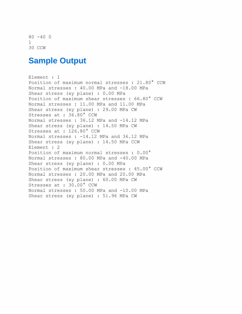
80 -40 0
1
30 CCW
Sample Output Element : 1
Position of maximum normal stresses : 21.80° CCW
Normal stresses : 40.00 MPa and -18.00 MPa
Shear stress (xy plane) : 0.00 MPa
Position of maximum shear stresses : 66.80° CCW
Normal stresses : 11.00 MPa and 11.00 MPa
Shear stress (xy plane) : 29.00 MPa CW
Stresses at : 36.80° CCW
Normal stresses : 36.12 MPa and -14.12 MPa
Shear stress (xy plane) : 14.50 MPa CW
Stresses at : 126.80° CCW
Normal stresses : -14.12 MPa and 36.12 MPa
Shear stress (xy plane) : 14.50 MPa CCW
Element : 2
Position of maximum normal stresses : 0.00°
Normal stresses : 80.00 MPa and -40.00 MPa
Shear stress (xy plane) : 0.00 MPa
Position of maximum shear stresses : 45.00° CCW
Normal stresses : 20.00 MPa and 20.00 MPa
Shear stress (xy plane) : 60.00 MPa CW
Stresses at : 30.00° CCW
Normal stresses : 50.00 MPa and -10.00 MPa
Shear stress (xy plane) : 51.96 MPa CW